

Page 1

AUTOPRIME AL RANGE
CENTRIFUGAL PUMP
OPERATORS INSTRUCTIONS
AUTOPRIME
AL RANGE
DIESEL DRIVEN
MOBILE PUMPS
SPP Pumps Limited
Crucible Close
Mushet Industrial Park
Coleford, Glos
ENGLAND
GL16 8PS
Telephone:
+44 (0)1594 832 701
Fax:
+44 (0)1594 836 300
Document No: W72-025E
Revision No: 3
Revision Note No: Windchill
Date Issued. Aug 2012
Produced at SPP Pumps
Limited, Coleford, England
Page 2
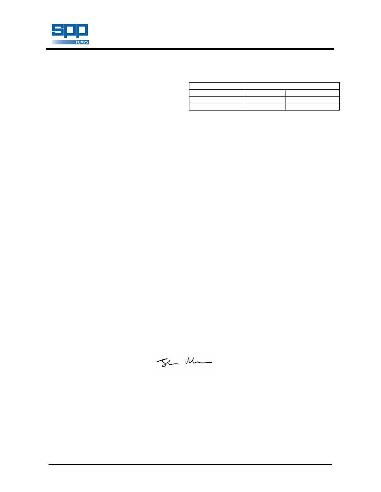
DECLARATION OF
Sound Level (dB)
We SPP Pumps Limited
Pump Model Measured Guaranteed LWA
AL100 & AL100M 103 106
AL150 & AL150M 103 106
Of Crucible Close 2000/14/EC- Guaranteed sound power level.
Mushet Industrial Park The conformity assessment procedure followed was
Coleford, Glos in according with ANNEX V of the Directive
GL16 8PS
ENGLAND
Declare that:
Equipment: DIESEL DRIVEN CENTRIFUGAL PUMPS
Model/Type: AL100 & AL100M, AL150 & AL150M
Serial Number: As shown on the Pump Nameplate
in accordance with the following Directives:
2004/108/EC The Electromagnetic Compatibility Directive and its amending directives
2006/42/EC The Machinery Directive and its amending directives
2000/14/EC The Noise Emissions Directive and its amending directives
have been designed and manufactured to the following specifications:
EN 809:1998+A1:2009 Pump and pump unit for liquids – common safety requirements
EN 12162: 2001 Liquid pumps – Safety requirements – Proceedure for hydrostatic testing.
EN 292-2: 1991 Safety of Machinery- Basic concepts, general principles for design.
EN 61000-6-4: 2001 Electromagnetic compatibility (EMC). Generic standards. Emission standard
for industrial environment.
EN 61000-6-1: 2001 Electromagnetic compatibility (EMC). Generic standards. Immunity for
residential, commercial and light-industrial environments.
EN 3744: 1995 Acoustics- Determination of sound power levels of noise sources using sound
pressure- Engineering method in an essentially free field over a reflecting
plane
CONFORMITY
We hereby declare that the equipment named above has been designed to comply with the relevant sections
of the above referenced specifications. The units comply with all essential requirements of the Directives
Signed:
Name: John Hollins
Position: Engineering Manager - Authorised to sign on behalf of SPP Pumps Limited
Mushet Industrial Park, Coleford, Gloucestershire, England, GL16 8PS
Date: August 2012
W72-025E
A copy of this certificate has been submitted to the European Commission and UK Authority
Our policy is one of continuous improvement and we reserve the right to alter specifications at any time
Page 2 of 12
Page 3

Operators Instructions for
AL100 & 150 Diesel Driven Centrifugal Pumps
Manual No/Rev
W72-025E / 3
CONTENTS
1 INTRODUCTION ....................................... 4
2 SAFETY PRECAUTIONS .......................... 5
2.1
Safety Symbols ......................................................... 5
2.2
Pump Safety Precautions ......................................... 5
3 HANDLING & TRANSPORT ..................... 5
3.1
Lifting ........................................................................ 5
3.2
Road Trailer Version ................................................. 5
3.3
Trailer or Wagon Carriage ........................................ 5
4. OPERATING INSTRUCTIONS .................. 6
4.1
Starting ..................................................................... 6
4.2
Control Panel ............................................................ 6
4.3
After Starting ............................................................. 7
4.4
Stopping .................................................................... 7
4.5
Emergency Stop (Where fitted) ................................ 7
4.6
Battery Isolation Switch (Where fitted) ..................... 7
5. Problem Solving by Operator ................. 7
5.1
Engine running but not pumping: .............................. 7
5.2
Pumping reduced with surging: ................................ 7
5.3
Pump fails to prime after starting: ............................. 7
5.4
Engine stops: ............................................................ 7
6. PUMP MAINTENANCE CHART ................ 8
7. MAINTENANCE INSTRUCTIONS ............. 8
7.1
Coalescer Maintenance ............................................ 8
7.2
Mechanical Seal Oil Reservoir.................................. 8
7.3
Drive Belt Adjustment ............................................... 8
7.4
Mechanical Seals...................................................... 9
7.5
Non-Return Valve ..................................................... 9
7.6
Pump Bearings ......................................................... 9
7.7
Vacuum Pump .......................................................... 9
7.8
Standard Vacuum Pump Air Filter ............................ 9
7.9
High Capacity Air Filter ........................................... 10
7.10 Valve Gear .............................................................. 10
7.11 Surge Control Valve ................................................ 10
8. FAULT FINDING GUIDE ......................... 11
9. TECHNICAL DATA ................................. 12
10. SPARES & SERVICE .............................. 12
11. ENGINE OPERATORS HANDBOOK...... 12
Our policy is one of continuous improvement and we reserve the right to alter specifications at any time
Page 3 of 12
Page 4

Manual No/Rev
SUCTION
PRIMING
VALVE
COVER
SURGE
CONTROL
AIR
TOWBAR
CONTROL
NON
RETURN
Not Shown
BATTERY AND
BELTS GUARD
SPP Pumps Limited
Reading, RG31 7SP
Tel: ++44(0)118 932 3123
W72-025E / 3
1 INTRODUCTION
AL100 & 150 Diesel Driven Centrifugal Pumps
The purpose of this handbook is to provide
operating guidelines and routine maintenance
instructions for the SPP AUTOPRIME AL
Range of mobile diesel engine driven pumps.
Instructions and statements contained within
this handbook are given with our best
intentions and are correct at the time of
compilation. They are subject to alteration at
any time.
These pumps are most commonly supplied
mounted on 4 wheel site trailers but can also
be supplied mounted on 2 wheel road trailers
or skid mounted.
AL pumps are primed by a vacuum pump
through a mechanical priming system and are
driven by a water-cooled diesel engine.
The M series pumps are supplied with a high
performance impeller.
PANEL
RADIATOR
GUARD
FUEL
FILLER
Operators Instructions for
This Handbook covers the following pumps:
AL100
mobile pump driven by an Isuzu 3CD1 diesel
engine mounted on a fuel tank chassis on
site or road trailer or on a skid. This unit is
fitted with 4” Bauer hose connections.
ACE150
mobile pump driven by a Isuzu 4LE1 diesel
engine mounted on a fuel tank chassis on
site or road trailer or on a skid. This unit is
fitted with 6” Bauer hose connections.
SERIAL NUMBER
The serial number plate is attached to the
unit on the side of the priming tank.
This serial number must be quoted in any
enquiry for spares or service.
Where required, a trailer registration plate is
fitted to the front of the unit as required by
local regulations and the VIN number is
stamped on the fuel tank.
RADIATOR
FILTER
UNIT
LIFTER
and 100M – An automatic priming
and 150M – An automatic priming
VALVE
TANK
VALVE
FLANGE
DRAIN
VALVE
PIVOTING
VACUUM
PUMP
COALESCER
AL 100 & 150 MAIN COMPONENTS
Type
kg
Fax: 118 932 3302++44(0)
ENGLAND
Nett
Serial No.
AL RANGE NAMEPLATE
Our policy is one of continuous improvement and we reserve the right to alter specifications at any time
Page 4 of 12
Page 5

Operators Instructions for
AL100 & 150 Diesel Driven Centrifugal Pumps
2 SAFETY PRECAUTIONS
2.1 Safety Symbols
Safety instructions within this manual are
marked with the following symbols:
This symbol refers to general mechanical
aspects of safety.
This symbol refers to electrical safety.
ATTENTION
2.2 Pump Safety Precautions
1. Hot surfaces and moving parts are guarded
2. Never insert anything into the pump casing
3. Collapsible hoses must not be used on the
4. Where the standard Bauer connections are
5. Do not lift with fork of fork lift truck under
6. Always lift pump sets vertically by the lifting
7. Check the type of liquid being pumped
8. Personnel working on the pump unit must
9. Always allow adequate ventilation for diesel
This symbol gives warning of a
hazard to the pump itself, which in
turn could cause a risk to personal
safety.
ATTENTION
apply to all the following:-
to protect you. If these guards are removed
for maintenance, they must be replaced
before starting the pump.
whilst the pump is running with the suction
and delivery hoses disconnected.
suction side of the pump
not used, use all pump flange holes to fit
suction and delivery hose connections.
the fuel tank. Never lift with suction or
delivery hoses attached. The increased
weight of these items may cause lifting gear
failure.
eye. Check the condition of the lifter
bracket at regular intervals.
before working on pump ends. Residues
could be hazardous to your health. If in
doubt flush out with clean water before work
commences.
always wear clean correctly fitting clothing
and safety footwear. Clothing impregnated
with oil or fuel can constitute a health
hazard through prolonged contact with the
skin and may also constitute a fire hazard.
Manual No/Rev
W72-025E / 3
engines. Be aware of fire risks from items
such as exhaust pipes and silencers.
Never place flammable items around the
unit.
10. When working near to the pump or in a
confined space with the pump running
personal ear protection is recommended.
3 HANDLING & TRANSPORT
3.1 Lifting
The central lifting eye is designed for lifting
only the pump unit as supplied by SPP
Pumps Limited. Due to the additional
weight of skid-mounted units, these may be
fitted with alternative lifting points and forklift truck slots on the skid.
The central lifting eye is suitable only for
vertical lifting and must not be used to
pull the unit sideways.
1. Check the condition of the central lifting eye
or bracket before use.
2. Do NOT use a lift truck with forks under the
fuel tank and do NOT lift with the hoses
attached.
3. Never allow the unit to be subject to a
‘snatch’ loading.
4. Control the unit while lifting to prevent
swinging and keep personnel away from the
area below the unit and the immediate area.
3.2 Road Trailer Version
There is provision for a lighting board to be
fitted to the rear of the unit. Place the
lighting board in the two brackets and insert
pins to retain the lighting board in place.
3.3 Trailer or Wagon Carriage
Transportation on a trailer or wagon will
require the unit to be roped or strapped
down. On the road trailer mounted units,
set the unit level with the front and rear prop
stands lowered and clamped. Place ropes
or straps over the chassis to hold the unit in
place. Do NOT place ropes or straps over
the engine or the pump unit and ensure that
ropes or straps do not come into contact
with controls, switches, taps or other
vulnerable parts.
Our policy is one of continuous improvement and we reserve the right to alter specifications at any time
Page 5 of 12
Page 6

Manual No/Rev
W72-025E / 3
4. OPERATING INSTRUCTIONS
AL100 & 150 Diesel Driven Centrifugal Pumps
Operators Instructions for
4.1 Starting
1. Read this the safety and operating
instructions on the pump and in this
handbook carefully.
2. Position the pump set on level ground and
chock in place to prevent movement in use.
3. Connect suction and delivery hoses making
sure that there are no sharp bends in the
lines. Where the hoses pass over sharp
edges or abrasive surfaces ensure that they
are protected by suitable means to prevent
chafing. Ensure that the suction hose end is
fully submerged.
ATTENTION
7. Select and fit a strainer to the suction hose
end with holes smaller than:
AL100 44mm Diameter
AL150 50mm Diameter
8. Ensure that the strainer and suction hose
end is fully submerged.
10. Check for sufficient fuel using the fuel tank
gauge.
11. Check for sufficient engine lubricating oil
using the dipstick.
12. Check for sufficient engine coolant
13. Ensure the engine is cold and remove the
radiator filler cap. The correct level is when
coolant is just visible at the base of the filler
neck.
14. Check that oil is present in the pump seal
reservoir.
15. Ensure that the batteries are charged and
ready for use.
16. Where fitted, ensure that the battery
isolation switch is in the ON position.
17. Check the air filter monitor (LH below
engine air cleaner). If reading is greater
than 12" remove filter and clean.
18. Check coalescer oil level on the dipstick
and ensure dipstick is fully tightened.
19. Ensure drain cocks in the discharge line
and volute are closed.
Our policy is one of continuous improvement and we reserve the right to alter specifications at any time
Page 6 of 12
4.2 Control Panel
AL100 and AL100M Control Panel
The AL100 control panel comprises:
a) Four position key-switch (Off, 1, Heat, Start)
c) An hours run meter.
d) Eight warning indicator lamps (All are red
except where shown)
1. High engine temperature – Engine will
shutdown on high engine temperature.
2. Emergency Stop – Flashes and
shutdown when circuit is broken.
3. Spare.
4. Preheat (Amber for 4 secs.) information
only.
5. On / off indicator (Green) – Flashes on
shutdown.
6. Battery Charge – Shutdown on loss of
charging.
7. Engine oil pressure – Shutdown on loss
of oil pressure.
8. Preheat (Amber for 16 secs.)
information only.
AL150 and AL150M Control Panel
The AL150 panel comprises:
a) Four position key-switch (Off, 1, Heat, Start)
c) An hours run meter.
Page 7

Operators Instructions for
AL100 & 150 Diesel Driven Centrifugal Pumps
d) Five warning indicator lamps
1 On / off indicator
2 Engine oil pressure
3 High engine temperature
4 Not Used
5 No Charge
1 Turn the ignition switch to the '1' position.
The ‘ON’ indicator will show green and all
warning lights will flash, indicating that all
circuits are healthy.
2 Switch OFF.
3 Turn the key-switch directly to the ‘Heat’
position and hold for 6 to 10 seconds. Note
that the timer will cut out the heater after 16
seconds.
4 Turn the key-switch on to the 'START'
position for a maximum of 16 seconds.
Release the key switch once the engine has
fired and is running.
5 If the engine fails to start, wait 20 seconds
and repeat steps 5 and 6.
4.3 After Starting
The pump will prime automatically once the
suction hose is submerged.
4.4 Stopping
1. Turn the key-switch to the 'OFF’ position.
The unit will stop and the key can be
removed.
2. Open the discharge cock to drain the
discharge line. Close after draining is
complete.
3. Open the volute cock to drain the volute.
Close after draining is complete.
4. Remove the key to prevent unauthorised
use.
4.5 Emergency Stop (Where fitted)
1. While the pump is running, if the pump has
to be stopped quickly, an emergency stop
button may be provided. When pressed the
engine and pump will stop.
2. To reset the emergency stop, turn off the
key-switch and turn the emergency stop
button to release it. The pump is now ready
Manual No/Rev
W72-025E / 3
for starting again.
4.6 Battery Isolation Switch (Where fitted)
1. A battery isolation switch may be specified
for additional security and for ease of
maintenance. This is located adjacent to the
control panel.
2. When the unit is to be stored or is not
required for immediate use, turn the
isolating switch to the OFF position.
3. When the pump is required for use turn the
battery isolation switch to the ON position.
5. Problem Solving by Operator
In all the cases below, STOP the pump
before attempting to correct the problem.
5.1 Engine running but not pumping:
Check suction pipe for leaks, ensure all
hose fittings are air tight.
Check for blockage of the strainer, and
clear any debris.
Check for damage to the suction hose both
externally and internally, replace damaged
hose.
5.2 Pumping reduced with surging:
Check that the impeller is clear of debris
and remove debris, if present.
Check the non-return valve is clear.
5.3 Pump fails to prime after starting:
Check suction hoses for leaks and ensure
all hose fittings are air tight.
Check that volute drain cock is closed.
Check that the non-return valve is free of
debris and can seal when closed.
5.4 Engine stops:
Check engine fuel level, and refuel if
necessary.
Check warning indicator lamps and correct
any faults indicated.
Our policy is one of continuous improvement and we reserve the right to alter specifications at any time
Page 7 of 12
Page 8

Manual No/Rev
W72-025E / 3
AL100 & 150 Diesel Driven Centrifugal Pumps
Operators Instructions for
6. PUMP MAINTENANCE CHART
For engine maintenance periods refer to the engine operators handbook supplied with this manual.
PERIOD TASK
Daily Visually check for leaks and vibrations
Check for vibration.
Check the mechanical seal oil level and top up as required.
Drain any water from coalescer, check oil level and top up as required
Weekly or
100 hrs
Monthly or
500 hrs
6 monthly
or 1500 hrs
Annually or
6000 hrs
The above schedule is given for guidance but site operating conditions may override the suggested
maintenance intervals
.
7. MAINTENANCE INSTRUCTIONS
7.1 Coalescer Maintenance
1. Check the oil level in the coalescer tank and
drain any water daily. The top of the oil
should be level with the underside of the
filler cap. Water is removed by means of
the drain tap fitted to the side of the
coalescer sump.
Check all fastener security.
Check the condition of the lifter bracket/frame and check the security of attachment to
the unit.
Check tension of vacuum pump drive belt.
Change coalescer sump oil
Clean coalescer sump oil filter mesh
Remove front cover and check pump internals for wear
Check valve gear - clean or renew standard filter element. Check high capacity filter
element.
Grease the pump bearings
Check reflux ball is sealing on its seat.
Check and if necessary renew vacuum pump drive belt.
Dismantle and clean valve gear, tank, connecting pipes and priming tank.
Change mechanical seal oil.
Check vacuum pump blade condition
Check bearing condition
Renew coalescer filter mesh
2. The filter mesh is accessed by removing the
coalescer lid and must be cleaned regularly
by washing in petrol or a similar spirit.
When refitting ensure filter mesh is below
exhaust port. The oil feed pipe should be
cleaned in a similar manner and blown
through with an air line.
7.2 Mechanical Seal Oil Reservoir
Maintain the oil level between the maximum
and minimum levels marked on the dipstick.
7.3 Drive Belt Adjustment
1. Remove the drive belt guard.
2. Slacken the nuts that secure the vacuum
pump, move the vacuum pump to give the
required belt tension and tighten the nuts.
Check the tension again and readjust, if
necessary.
3. V Belt tension is correct when the deflection
is 4mm with a force of 1.5kg applied at the
centre of top run.
Coalescer detail
Our policy is one of continuous improvement and we reserve the right to alter specifications at any time
Page 8 of 12
Page 9

Operators Instructions for
VACUUM PUMP NUTS
AL100 & 150 Diesel Driven Centrifugal Pumps
FORCE
DEFLECTION
Belt Tensioning
Note: DO NOT OVERTIGHTEN BELTS
UNDER ANY CIRCUMSTANCES.
7.4 Mechanical Seals
1. Ensure that the coolant/lubricant level is
maintained. It is imperative that the seals
are never run dry. Immediate seal failure
will result.
2. Any contamination of the fluid should be
investigated immediately. Should a large
loss of fluid be experienced then the pump
must be stopped immediately.
3. Replacement of the seals is considered a
workshop operation where higher standards
of cleanliness can be maintained and the
specialised tooling required is more readily
available.
7.5 Non-Return Valve
1. A ball type non-return valve is fitted to the
pump discharge.
2. The ball should be regularly checked for
freedom of movement and absence of
debris by inspection through the discharge.
3. The correct seating of the ball can be
checked through the delivery flange of the
valve body. The valve body should be
removed to check the seat for damage or
wear.
7.6 Pump Bearings
1. The pump ends employ grease lubricated
bearings which will give long service life
provided they are:-
a)
Correctly lubricated at regular intervals
b)
Cleaned and, if removed, refitted with care
c)
Serviced with clean tools and in a clean
area.
2. The early stages of bearing failure can be
detected by noting either unusual vibration,
Manual No/Rev
W72-025E / 3
bearing housing temperature rise or unduly
noisy operation. If any of these signs are
notice, the pump should be stopped and the
cause investigated.
3. Greased bearings are pre-packed with
lubricant during pump manufacture.
Shrinkage and normal loss of grease
necessitates re-lubrication at regular
intervals. These intervals will largely be
determined by site conditions. The
recommendations given below are therefore
for guidance only.
Radial Bearing
Non drive end
(NDE)
4 months
3000 hrs
4. The table is based on running speeds of
1450rpm with a bearing temperature not
exceeding 70°C. Reduce the interval by half
for every 15°C above 70°C.
5. Clean both the grease fittings and grease
gun nozzle before use. For a hand grease
gun apply 2 or 3 strokes to each nipple.
6. Overfilling can be as harmful to bearings as
under-lubrication. Compaction of grease
leads to it being churned by the rolling
action of the bearings. This leads to
overheating, breakdown of the lubricant and
bearing failure.
7. Immediately after re-lubrication it is normal
for the temperature of the bearing housing
to rise in service. The temperature should
soon drop to normal after a short period of
running. If the temperature remains
elevated or continues to rise, temporarily
remove the grease nipples and allow any
excess grease to escape.
7.7 Vacuum Pump
Vacuum pump overhaul is beyond the
scope of this manual. Should the vacuum
pump be suspect then it is recommended
that an exchange unit is fitted and the
suspect unit returned to the manufacturers
for examination.
7.8 Standard Vacuum Pump Air Filter
Standard air filters are located in the valve
cover of the primary tank and should be
checked regularly for cleanliness, distortion
or damage (see Figure 7-5, Figure 7-6,
Figure 7-7). Replace if distorted or
damaged
Radial & Thrust
Bearing
Drive end (DE)
4 weeks
750 hrs
Our policy is one of continuous improvement and we reserve the right to alter specifications at any time
Page 9 of 12
Page 10

Manual No/Rev
AIR FILTER
25PTFLTA
AIRFILTER
60PTFLT
A
60AFELE
A
KNOB (NOT SHOWN)
SPRING
W72-025E / 3
AL100 & 150 Diesel Driven Centrifugal Pumps
Remove the four screws holding the filter
cover and remove to expose the air filter
element.
Air filter 25cfm units
Undo the central nut holding the air filter
cover and remove to expose the filter
element.
Air filter 60cfm units
Undo the six nuts holding the top cover and
remove the top cover complete to expose
the air filter element.
7.9 High Capacity Air Filter
25cfm and 60cfm vacuum pumps have the
option of a high capacity air filter which is
located externally as shown in Figure 7-8
The high capacity filter is fitted in lieu of the
standard element.
1
2
High capacity air filter
Undo the screws holding the retaining cover
and remove (1) the cover to inspect the
filter. The element pulls out (2). Note that
the orientation of the unit should be as
shown so that any debris from the filter falls
away from the outlet connection when the
unit is opened. It can then can easily be
swept out with little chance of it entering the
outlet. Replace the cover O ring when the
filter is changed.
7.10 Valve Gear
The main valve assembly is shown below.
The areas arrowed should be checked
regularly for wear or damage. Worn parts
Our policy is one of continuous improvement and we reserve the right to alter specifications at any time
Operators Instructions for
should be replaced. The main valve is
located on the underside of the top cover.
7.11 Surge Control Valve
On 25 and 60cfm priming tanks a surge
control valve is fitted. This should be
checked regularly for signs of wear or
damage. Components arrowed in the figure
below are vulnerable to wear and should be
replaced if worn excessively. The valve seat
should be greased to prevent seizure.
Page 10 of 12
60PTVLVA.PCX
25 & 60cfm main valve assembly
VALVE SEAT
VALVE SPINDLE
KLIP RING
VALVE
M8 WASHER
SPRING RETAINER
KLIP RING
Surge Control Valve Assembly
Page 11

AL100 & 150 Diesel Driven Centrifugal Pumps
8. FAULT FINDING GUIDE
Pump Fails to Prime
Are
NO
all plugs
tight?
NO YES
Operators Instructions for
Disconnect suction hose
Blank off suction entry
Fit vacuum gauge
Reading
between
85 - 89 .5 kpa
(28.5 0 30 ft H20)?
Manual No/Rev
W72-025E / 3
Check vertical
suction lift
Rectify &
re-test
Fit vacuum gauge
(28.5 0 30 ft H20)?
NO
Is belt drive
tension OK?
YES
Test the Vacuum
Pump directly
Reading
between
85 - 89 .5 kpa
NO
YES
Rectify YES
Rectify NO
Is
Reflux Valve
Ball seating
properly?
YES
Is Vacuum
Pump filter
blocked?
NO
Is Main
Valve float
gear free and
intact?
YES
Move
Pump
YES
NO
Rectify
Lift< or =
8.53m (28ft) for
ACE80/100
NO
Are hoses
leaking, collapsed
or blocked?
NO
Is intake
blocked?
NO
Is impeller
blocked?
YES
Rectify
YES
Rectify
YES
Rectify
YES
Excessive wear.
Remove Vacuum
Pump & either
overhaul or fit new or
exchange pump
Rectify
NO
Rectify
YES
Is pump
casing free from
holes?
ACE80-100 Fault Finding Chart
Are all
joints sound &
leak free?
YES
Check impeller wear
plate clearances
and rectify
NO
Rectify
Is the
pump or NRV
blocked or
damaged?
NO
YES
Rectify
Our policy is one of continuous improvement and we reserve the right to alter specifications at any time
Page 11 of 12
Page 12

Manual No/Rev
Vacuum Pump
25 cfm
60 cfm
Solids Handling Capability
44mm Dia.
50mm Dia.
KP2\K-30
1463mm
1900mm
750mm
1
3
7
7
m
m
W72-025E / 3
AL100 & 150 Diesel Driven Centrifugal Pumps
Operators Instructions for
9. TECHNICAL DATA
CHARACTERISTICS AL100 & AL100M AL150 & AL150M
Engine Type Isuzu 3CD1 Water cooled Isuzu 4LE1 Water cooled
Fuel Tank Capacity 76 Litres
Approx. Running Time On Full Tank 22 Hours
Impeller Back Plate Clearance 0.30 to 0.60 mm 0.012 to 0.024"
Impeller Front Plate Clearance 0.40 to 0.60 mm 0.015 - 0.024"
Mechanical Seal Coolant/Lubricant Mobil Velocite Oil No. 6, Texaco Rando HD10 Or equivalent
Bearing Lubricant
Vacuum Pump Oil
Weight Dry (No fuel in tank) 900 Kg
Weight (With full fuel tank) 970 Kg
above 300C
below 300C
Grease: Texaco Multifak All Purpose EP2 or equivalent to DIN 51825:
Texaco Regular Motor oil 30
5F, CCMC G2.D1, MIL-L-2104B or MIL-L-46152B *
Texaco Ursatex 10W-30
CCMC G2.D1, MIL-L-2104B or MIL-L-46152B *
or equivalents conforming to API CC
or equivalents conforming to API CC 5F,
AL100 & 100M OVERALL DIMENSIONS
Note - These dimensions are approximate and may vary to suit the selected customer options.
10. SPARES & SERVICE
SPP Pumps operate a comprehensive Spares and Service support network throughout the world, and
can be contacted as follows:
SPARES & SERVICE Telephone: +44 (0)1189 323 123
For spare parts, supply only. Ask for - Spares Dept.
For breakdowns, spare parts and on-site fitting, pump installation and
commissioning, and service contracts. Ask for - Service Dept.
For breakdowns outside office hours. Telephone : +44 (0)1189 323 123
Spares & Service Office
SPP Pumps Limited General Fax line: +44 (0)1189 323 302
Theale Cross
Reading, Berkshire Direct Fax line: +44 (0)1189 303 259
RG31 7SP
ENGLAND
Copies of this manual are available from the SPP Pumps Limited Spares & Service Department by
quoting the manual reference number and the relevant revision number.
11. ENGINE OPERATORS HANDBOOK
The specific engine operator’s handbook from the manufacturer is included within the pump
documentation pack.
Our policy is one of continuous improvement and we reserve the right to alter specifications at any time
Page 12 of 12
 Loading...