

Page 1
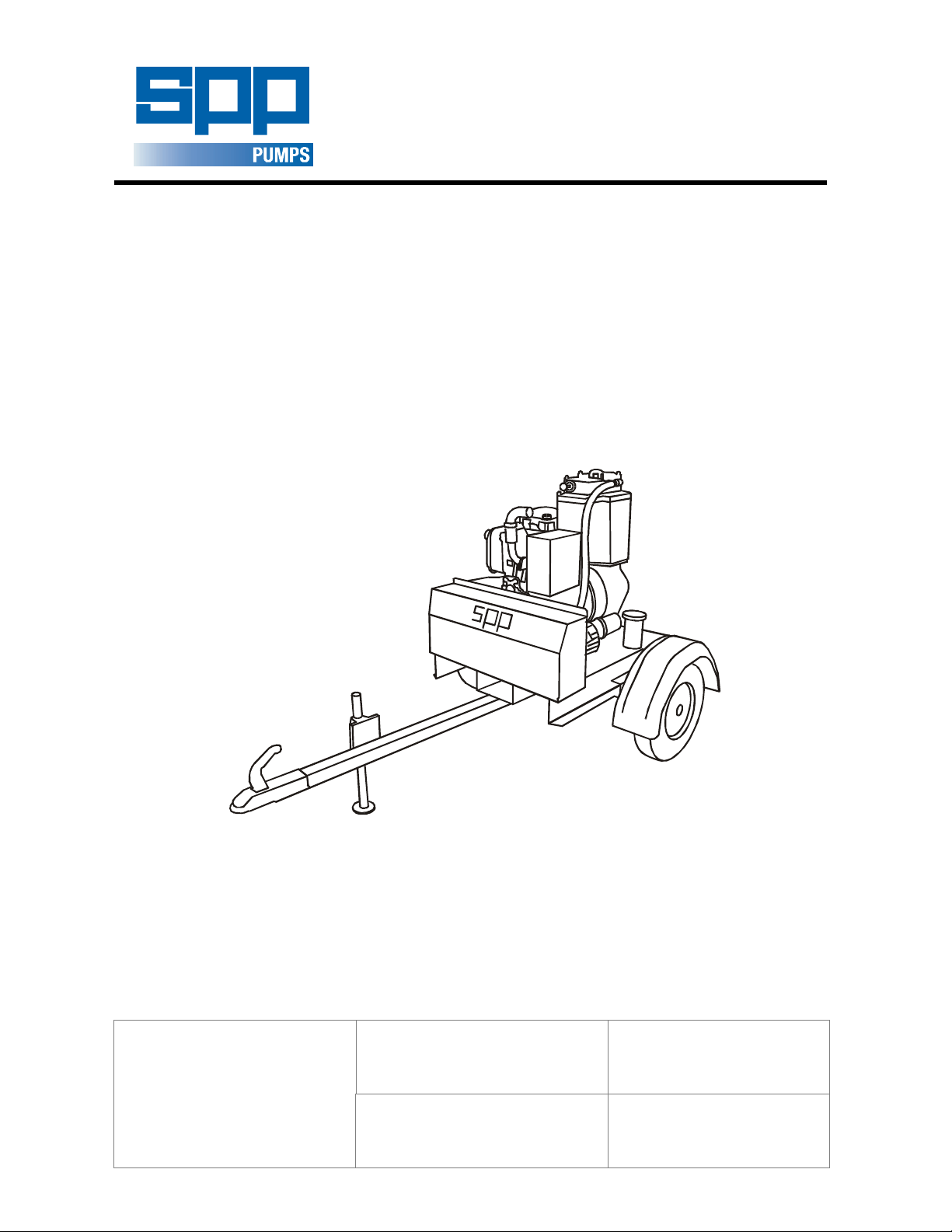
AUTOPRIME ACE RANGE
CENTRIFUGAL PUMP
WORKSHOP MANUAL
AUTOPRIME
ACE RANGE
DIESEL DRIVEN
MOBILE PUMPS
SPP Pumps Limited
Crucible Close
Mushet Industrial Park
Coleford
Gloucestershire
GL16 8PS
Our policy is one of continuous improvement and we reserve the right to alter specifications at any time
This manual is a preliminary issue
for information only,
pending formal issue of
the complete manual.
Telephone:
+ 44 (0)1594 832 701
Fax:
+ 44 (0)1594 836 300
Page 1 of 21
Document No: W72-020E
Revision No: Preliminary 2
Revision Note No: Windchill
Date Issued. Aug 2012
Produced at SPP Pumps
Limited, Coleford, England
Page 2

Manual No/Rev
Workshop Manual for
W72-020E / 1
ACE80/100 Diesel Driven Centrifugal Pumps
CONTENTS
1. INTRODUCTION...................................................... 3
2. SERIAL NUMBER ................................................... 3
3. SAFETY PRECAUTIONS ........................................ 4
6.1 Safety Symbols ................................................................ 4
6.2 Pump Safety Precautions ................................................. 4
4. HANDLING & TRANSPORT ................................... 4
6.1 Lifting ................................................................................ 4
6.2 Road Trailer Version ........................................................ 4
6.3 Trailer or Wagon Carriage ................................................ 4
5. FAULT FINDING GUIDE ......................................... 5
6. MAINTENANCE & REPAIR .................................... 6
6.1 A - Check & Service the Non Return Valve ...................... 6
6.2 B -Check & Service the Vacuum Air Filter ....................... 6
6.3 C - Check & Service the Priming Tank ............................. 6
6.4 D - Check Vacuum Pump Belt Tension ............................ 6
6.5 F – Full Pump Stripdown for Overhaul ............................. 7
7. PUMP ASSEMBLY PROCEDURE .......................... 8
6.1 Pump End Section Drawing ............................................. 8
6.2 Pump End Parts List: ........................................................ 9
6.3 Pump End Assembly (See section 7.1) ............................ 9
6.4 Priming Tank Parts List: ................................................. 10
6.5 Priming Tank Section Drawing ....................................... 10
6.6 Priming Tank Assembly .................................................. 12
6.7 Basic Pump Unit Construction........................................ 12
6.8 Option Builds .................................................................. 14
6.9 Final preparation ............................................................ 15
8. PUMP TEST PROCEDURE ....................................15
6.1
ENGINE, DRIVE, BATTERY & FITTINGS ..................... 16
6.2
BAUER FITTINGS .......................................................... 18
9.1
80-18 .............................................................................. 18
9.1
100-18 ............................................................................ 18
9.1
LABELS & TRANSFERS ................................................ 18
9.2
WIRING DIAGRAM ........................................................ 19
10. PARES & SERVICE ...............................................21
Our policy is one of continuous improvement and we reserve the right to alter specifications at any time
Page 2 of 21
Page 3
Workshop Manual for
ACE80/100 Diesel Driven Centrifugal Pumps
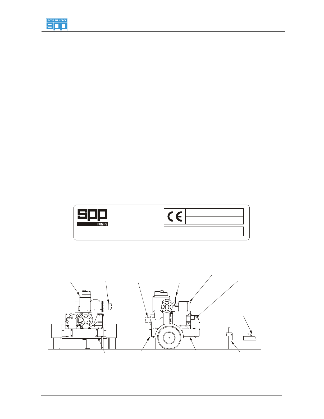
LIFTING
KEY
MOUNTING
STAND
DELIVERY
SUCTION
PRIMING
ENGINE
TANK
SPP Pumps Limited
Reading, RG31 7SP
Tel: ++44(0)118 932 3123
1. INTRODUCTION
The purpose of this handbook is to provide
repair and assembly instructions for the SPP
AUTOPRIME ACE Range of mobile diesel
engine driven pumps.
Instructions and statements contained within
this handbook are given with our best
intentions and are correct at the time of
compilation. They are subject to alteration at
any time.
These pumps are most commonly supplied
mounted on 2 wheel road trailers but can
also be supplied skid mounted, or as a pump
unit for customer’s to mount on a suitable
chassis or foundations.
ACE pumps are primed by a 25cfm vacuum
pump and are driven by a close coupled, aircooled diesel engine.
Manual No/Rev
W72-020E / 1
This Handbook covers the following pumps:
ACE80
driven by a Hatz 1D90 diesel engine
mounted on a fuel tank and road trailer or
skidThis unit is fitted with 3” Bauer hose
connections.
ACE100
pump driven by a Hatz 1D90 diesel engine
mounted on a fuel tank and road trailer or
skid. This unit is fitted with 4” Bauer hose
connections.
– An automatic priming mobile pump
– An automatic priming mobile
2. SERIAL NUMBER
The serial number plate is attached to the
unit on the side of the priming tank.
This serial number must be quoted in any
enquiry for spares or service.
Where required, a trailer registration plate is
fitted to the front of the unit as required by
local regulations and the VIN number is
stamped fuel tank.
TANK
Type
Nett
Fax: 118 932 3302++44(0)
BAUER
ENGLAND
Serial No.
ACE Range Pump Components
BAUER
EYE
This manual is a preliminary issue
for information only,
pending formal issue of
the complete manual.
LIGHTING BOARD
FUEL
kg
START
TOW
HITCH
JACK
Our policy is one of continuous improvement and we reserve the right to alter specifications at any time
Page 3 of 21
Page 4
Manual No/Rev
Workshop Manual for
W72-020E / 1
ACE80/100 Diesel Driven Centrifugal Pumps
3. SAFETY PRECAUTIONS
6.1 Safety Symbols
Safety instructions within this manual are
marked with the following symbols:
This symbol refers to general mechanical
aspects of safety.
This symbol refers to electrical safety.
ATTENTION
6.2 Pump Safety Precautions
apply to all the following:-
2.2.1
2.2.2
2.2.3
2.2.4
2.2.5
2.2.6
2.2.7
2.2.8
2.2.9
This symbol gives warning of a hazard
to the pump itself, which in turn could
cause a risk to personal safety.
ATTENTION
Hot surfaces and moving parts are guarded
to protect you. If these guards are removed
for maintenance, they must be replaced
before starting the pump.
Never insert anything into the pump casing
whilst the pump is running with the suction
and delivery hoses disconnected.
Collapsible hoses must not be used on the
suction side of the pump
Where the standard Bauer connections are
not used, use all pump flange holes to fit
suction and delivery hose connections.
Do not lift with fork of fork lift truck under the
fuel tank. Never lift with suction or delivery
hoses attached. The increased weight of
these items may cause lifting gear failure.
Always lift pump sets vertically by the lifting
eye. Check the condition of the lifter bracket
at regular intervals.
Check the type of liquid being pumped
before working on pump ends. Residues
could be hazardous to your health. If in
doubt flush out with clean water before work
commences.
Personnel working on the pump unit must
always wear clean correctly fitting clothing
and safety footwear. Clothing impregnated
with oil or fuel can constitute a health hazard
through prolonged contact with the skin and
may also constitute a fire hazard.
Always allow adequate ventilation for diesel
engines. Be aware of fire risks from items
such as exhaust pipes and silencers. Never
place flammable items around the unit.
2.2.10
When working near to the pump or in a
confined space with the pump running
personal ear protection is recommended.
4. HANDLING & TRANSPORT
6.1 Lifting
The central lifting eye is designed for lifting
only the pump unit as supplied by SPP
Pumps Limited. Due to the additional weight
of skid-mounted units, these may be fitted
with alternative lifting points and fork-lift
truck slots on the skid.
The central lifting eye is suitable only for
vertical lifting and must not be used to
pull the unit sideways.
4.1.1
Check the condition of the central lifting eye
or bracket before use.
4.1.2
Do NOT use a lift truck with forks under the
fuel tank and do NOT lift with the hoses
attached.
4.1.3
Never allow the unit to be subject to a
‘snatch’ loading.
4.1.4
Control the unit while lifting to prevent
swinging and keep personnel away from the
area below the unit and the immediate area.
6.2 Road Trailer Version
There is provision for alighting board to be
fitted to the rear of the unit. Place the
lighting board in the two brackets and insert
pins to retain the lighting board in place.
6.3 Trailer or Wagon Carriage
Transportation on a trailer or wagon will
require the unit to be roped or strapped
down. On the road trailer mounted units, set
the unit level with the front and rear prop
stands lowered and clamped. Place ropes
or straps over the chassis to hold the unit in
place. Do NOT place ropes or straps over
the engine or the pump unit and ensure that
ropes or straps do not come into contact
with controls, switches, taps or other
vulnerable parts.
Our policy is one of continuous improvement and we reserve the right to alter specifications at any time
Page 4 of 21
Page 5
Worksh
op Manual for
ACE80/100 Diesel Driven Centrifugal Pumps
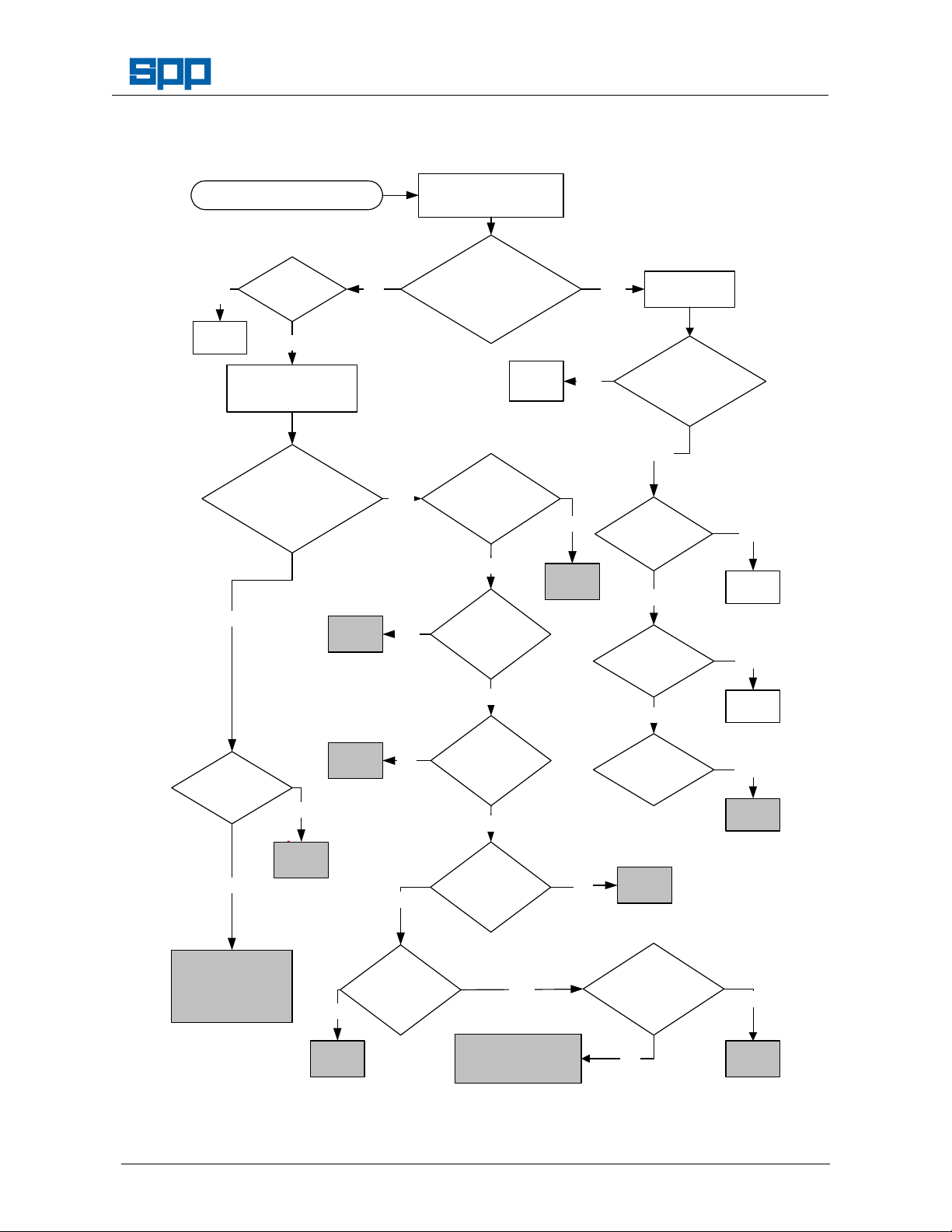
5. FAULT FINDING GUIDE
Pump Fails to Prime
Are
NO
all plugs
tight?
NO YES
Disconnect suction hose
Blank off suction entry
Fit vacuum gauge
Reading
between
85 - 89 .5 kpa
(28.5 0 30 ft H20)?
Manual No/Rev
W72-020E / 1
Check vertical
suction lift
Rectify &
re-test
Fit vacuum gauge
(28.5 0 30 ft H20)?
NO
Is belt drive
tension OK?
YES
Test the Vacuum
Pump directly
Reading
between
85 - 89 .5 kpa
NO
Rectify
B
Rectify
C
YES
YES
NO
Is
Reflux Valve
Ball seating
properly?
YES
Is Vacuum
Pump filter
blocked?
NO
Is Main
Valve float
gear free and
intact?
YES
Move
Pump
YES
NO
Rectify
C
Lift< or =
8.53m (28ft) for
ACE80/100
NO
Are hoses
leaking, collapsed
or blocked?
NO
Is intake
blocked?
NO
Is impeller
blocked?
YES
Rectify
YES
Rectify
YES
Rectify
F
Rectify
This manual is a preliminary issue
YES
D
for information only,
YES
Are all
joints sound &
leak free?
NO
Rectify
F
pending formal issue of
Excessive wear.
Remove Vacuum
Pump & either
overhaul or fit new or
exchange pump
Our policy is one of continuous improvement and we reserve the right to alter specifications at any time
the complete manual.
NO
Rectify
F
Is pump
casing free from
holes?
ACE80-100 Fault Finding Chart
Page 5 of 21
YES
Check impeller wear
plate clearances
and rectify F
Is the
pump or NRV
blocked or
damaged?
NO
YES
Rectify
A
Page 6
Manual No/Rev
Wor
kshop Manual for
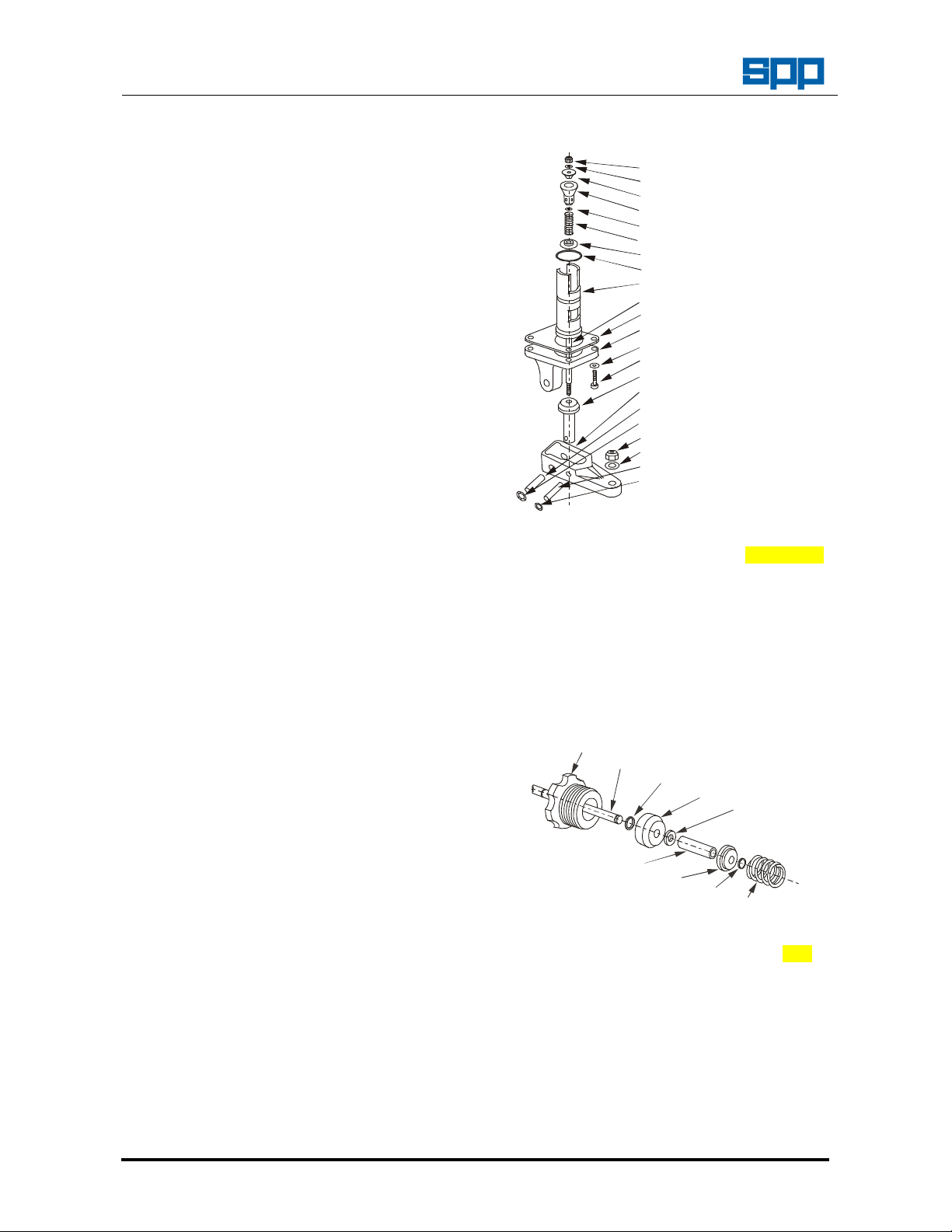
61 M4 SELF LOCK NUT
9 MAIN INLET VALVE
29 AIR OUTLET VALVE
64 M10 STARLOCK WASHER
24 KNOB (NOT SHOWN)
27 SPRING
W72-020E / 1
ACE80/100 Diesel Driven Centrifugal Pumps
6. MAINTENANCE & REPAIR
The extent of disassembly will depend upon the
faults identified for rectification from the fault
finding guide in section 5. The code letters relate
to the workshop rectification procedures outlined
below:
6.1 A - Check & Service the Non Return Valve
1. Refer to the pump end section drawing in
section 7.1
2. the Remove the Bauer hose connection from
the delivery flange.
3. Remove the four long bolts (83) and lift off
the non-return valve body (80).
4. Remove the non-return valve ball (81),
examine for surface damage and replace if
damaged sufficiently to prevent a good seal
with the valve seat (82).
5. Lift and examine the valve seat, refurbish if
possible or replace if damaged sufficiently to
prevent a good seal with the ball.
6.2 B -Check & Service the Vacuum Air Filter
1. Refer to the priming tank section drawing in
section 7.5
2. Remove the air filter cover (6) by unscrewing
the nut (50).
3. Lift out the filter assembly (17) and examine.
4. If the filter is damaged, replace, if blocked or
dirty, clean the filter with a suitable solvent,
dry and replace.
6.3 C - Check & Service the Priming Tank
1. Refer to the priming tank section drawing in
section 7.5
2. Remove the eight M10 nuts (51) that retain
the top cover of the priming tank and lift off
the cover complete with float valve. Set
aside on a clean surface for examination.
3. Check that the float (14) is intact and not
punctured, replace if damaged.
4. Check that the fulcrum arm moves freely
and is connected to the air outlet valve (29).
Look for signs of wear on the fulcrum and
valve pins (15 &16) and replace if worn.
5. Remove the four M6 capscrews (66) and
carefully withdraw the main valve assembly
from the top cover.
6. Disassemble the valve and examine all
valves, seats and pins for wear and replace
as necessary.
Our policy is one of continuous improvement and we reserve the right to alter specifications at any time
Page 6 of 21
56 NYLON WASHER
10 AIR INLET VALVE
57 M4 WASHER
13 SPRING
11 DIAPHRAGM
32 O RING
8 VALVE SEAT
7 VALVE ROD
36 GASKET
30 FULCRUM BRACKET
58 M6 WASHER
66 M6 CAPSCREW
31 FULCRUM ARM
15 FULCRUM PIN
62 M8 SELF LOCK NUT
59 M8 WASHER
16 VALVE SUPPORT PIN
63 M6 STARLOCK WASHER
Main Valve Assembly
7. Reassemble as per paragraphs XXX to XXX
8. Check the condition of reflux ball valve (19)
and the valve seat (18) replace if damaged
and confirm that the pipe (2) is securely
fitted to the valve seat.
9. Check the surge control valve for general
condition and cleanliness, confirm that the
valve and spring retainer are not worn,
replace if necessary.
20 VALVE SEAT
28 VALVE SPINDLE
65 KLIP RING
21 VALVE
67 M8 WASHER
23 DISTANCE PIECE
22 SPRING RETAINER
65 KLIP RING
Surge Control Valve
10. Refit the top cover as per paragraphs XXX
6.4 D - Check Vacuum Pump Belt Tension
1. Remove guard.
2. Slacken the locking nut and the retaining
bolt, rotate the tensioner to adjust the
tension of the belt. Tighten the locking nut
and the retaining bolt and check the tension
thus:
Page 7

Worksh
op Manual for
ACE80/100 Diesel Driven Centrifugal Pumps
FORCE
LOCKING
NUT
DEFLECTION
BOLT
RETAINING
Belt Tensioning
3. V Belt tension is correct when the deflection
is 4mm with a force of 1.5kg applied at the
centre of the longest run.
Note: DO NOT OVERTIGHTEN BELTS UNDER
ANY CIRCUMSTANCES.
Manual No/Rev
W72-020E / 1
6.5 F – Full Pump Stripdown for Overhaul
1. Refer to the pump assembly instructions in
section 7.
2. Full pump disassembly for examination of
internal clearances or for worn or damaged
parts is done generally in the reverse order
to pump assembly.
3. The use of suitable lifting equipment is
necessary to prevent injury and care must
be taken to remove any pumped liquids or
solids that may be hazardous to health
before commencing pump stripdown.
4. No special tools are required but the
installation of new mechanical seals will be
aided by the use of special tool no 22743.
This manual is a preliminary issue
for information only,
pending formal issue of
the complete manual.
Our policy is one of continuous improvement and we reserve the right to alter specifications at any time
Page 7 of 21
Page 8

Manual No/Rev
Wor
kshop Manual for
10
11
12
13
14
15
16
21
22
23
24
20
30
31
32
40
41
50
51
52
53
61
63
64
60
62
63
64
74
75
76
71
72
73
83
100
110
120
130
140
150
W72-020E / 1
ACE80/100 Diesel Driven Centrifugal Pumps
7. PUMP ASSEMBLY PROCEDURE
6.1 Pump End Section Drawing
80
81
260
82
90
91
92
93
94
70
77
78
Our policy is one of continuous improvement and we reserve the right to alter specifications at any time
Page 8 of 21
Page 9

Worksh
op Manual for
ACE80/100 Diesel Driven Centrifugal Pumps
210 Elbow:Male Stud
25346
-
221-000-7 1
250 Plug:3/8" Bsp
25221
-
383-915-0 1
6.2 Pump End Parts List:
Item Description Part No Qty
10 Engine:Hatz 1d90 *E41853B001* 1
11 Stud:M10x60 SY9509097 8
12 Washer:Spring M10 21174-306-927-6 8
13 Nut:Hex Full M10 21882-673-958-3 8
14 Stubshaft 22319 1
15 Capscrew:M8x25 21835-136-977-1 4
16 Washer:Spring M8 21174-305-927-9 4
20 Adaptor:Engine/Pump 22318 1
21 Stud:M10x30 SY9509089 8
22 Washer:Spring M10 21174-306-927-6 8
23 Nut:Hex Full M10 21882-673-958-3 8
24 'O'RING 199.5ID X 3.0 22384.017 1
30 Mech Seal 45 13763 1
31 Washer:Mech Seal 13938 1
32 Circlip: Ext 45 13772 1
40 Wearplate:Back Hsg 22317 1
41 O'RING 219.5ID X 3.0 22385.017 1
50 Mech Seal 45 13763 1
51 Impeller 22321 1
52 Shim:Impeller 1mm 22323 1
53 Shim:Impeller 0.5mm 22324 1
60 Volute 22655 1
61 Stud:M10x30 SY9509089 6
62 Stud:M10x25 SY9509087 6
63 Washer:Spring M10 21174-306-927-6 12
64 Nut:Hex Full M10 21882-673-958-3 12
70 Tee Piece 22320 1
71 Gasket SY5004439 1
72 Gasket SY5004432 1
73 Wear Plate SY3874016 1
74 Stud:M10x30 SY9509089 4
75 Washer:Spring M10 21174-306-927-6 4
76 Nut:Hex Full M10 21882-673-958-3 4
77 Screw:Hex Hd M12x40 21863-222-959-4 2
78 Nut:Hex Full M12 21882-673-958-3 2
80 Valve:Non-Return 22325 1
81 Ball:Nrv (Green) 8075 1
82 Seat:Nrv SY3874014 1
83 Bolt:Hex Hd M12x230 22326 4
90 Assy:Priming Tank SY3802500 1
91 Gasket SY5004373 1
92 Stud:M12x40 SY9509133 8
93 Washer:Spring M12 21174-307-927-3 8
94 Nut:Hex Full M12 21882-675-958-7 8
100
110 Adaptor:Male 15533 2
120 Valve:Ball 1/2" Bsp 22416 1
130 Hosetail 12149 1
140 Clip:Hose:18-25mm 5837 1
150 Hose 15446 600
160 Assy:Backprime Line *E41853A007* 1
170 Adaptor:Male 22606 1
180 Valve:Non Return SY3714105 1
This manual is a preliminary issue
for information only,
pending formal issue of
the complete manual.
Our policy is one of continuous improvement and we reserve the right to alter specifications at any time
Page 9 of 21
Manual No/Rev
W72-020E / 1
Item Description Part No Qty
190 Dipstick 14373 1
200 'O'RING 24.5ID X 3.0 25154-024-716-1 1
220 Clip:'P' Type 14150 1
230 Tube 17341-711-076-4 500
240 Adaptor:Male 22607 1
260 Plug:1/4" Bsp 25221-382-915-3 2
6.3 Pump End Assembly (See section 7.1)
1.1 Refer to the pump end section drawing in
section 7.1
1.2 Place engine (10) on a workbench that is
equipped with lifting equipment suitable to
lift the pump and engine assembly complete.
1.2 Fit eight M10 x 60 studs (11) onto the
engine flywheel casing.
1.3 Fit the stubshaft (14) onto the flywheel on
the engine with four M8 x 25 capscrews (15)
and spring washers (16).
1.4 Place the engine/pump adapter (20) over
the stubshaft and secure using the studs on
the engine with nuts (13) and spring
washers (12).
1.5 Fit eight M10 x 30 studs (21) into adapter.
1.6 Place the 199.5ID ‘O’ ring (24) over the
adapter.
1.7 Fit the secondary mechanical seal stationary
element (30) over the shaft and press it into
the adapter plate ensuring not to damage
the face.
1.8 Fit the rotating element of the mechanical
seal (30) and push it onto the shaft until the
circlip groove is exposed behind the seal.
1.9 Fit the circlip washer (31) followed by the
circlip (32) and ensure the mechanical seal
is securely in place and pulled back against
the circlip.
1.10 Fit the back wearplate (40) over the shaft
and secure using the studs in the adapter
plate with nuts (23) and spring washers (22).
1.11 Fit the remaining ‘O’ ring (41).
1.12 Fit the stationary seat of the primary
mechanical seal (50) over the shaft and
press into the wearplate.
1.13 Fit the rotational part of the mechanical seal
so that it touches the stationary seal face.
1.14 Screw on the impeller (51) (clockwise) and
check the back vane to wear plate clearance
is 0.5-1mm. If it does not fall within this
range, add shims (52 & 53) to give the
required clearance.
Page 10

Manual No/Rev
Wor
kshop Manual for
W72-020E / 1
ACE80/100 Diesel Driven Centrifugal Pumps
1.15 Pressure test the mechanical seal assy.
1.16 Fit six M10 x 30 studs (61) onto the back of
the volute (60).
1.17 Fit volute over the back wearplate and the
impeller and secure with M10 spring
washers (63) and nuts (64).
1.18 Fit six M10 x 25 studs (62) onto the front of
the volute.
1.19 Fit the large gasket (71) onto the studs on
the volute.
1.20 Fit four M10 x 30 studs (74) into the front
wear plate.
1.21 Fit the small gasket (72) onto the studs on
the front wearplate.
1.22 Fit wear plate onto the tee piece (70) using
four M10 nuts (76) and spring washers (75).
1.24 Fit tee piece onto volute using studs on
volute and secure with nuts (64) and spring
washers (63) check the clearance between
impeller and front wearplate if it is not within
the range of 0.5-1mm, adjust accordingly.
1.25 Fit the push off screws (77) and nuts (78).
1.26 Fit non-return valve ball (81) into non-return
valve (80).
1.27 Fit the seat (82) into the non-return valve.
1.28 Fit the non-return valve to the pump end
assy. using four M12 x 230 bolts (83)
screwed into the volute.
1.29 Fit the eight M12 x 40 studs (92) to the
bottom of the priming tank assembly (90).
1.30 Fit the gasket (91) onto the bottom of the
priming tank.
1.31 Fit the priming tank assembly onto the top of
the pump end assembly and secure with
nuts (94) and spring washers (93).
1.32 Fit non-return valve drain plug (260).
6.4 Priming Tank Parts List:
ITEM
1 Valve ball SY1544001 1
2 PVC Hose SY3404502 250
3 Float disc SY3404509 1
4 Top cover SY3474510 1
5 Valve cover SY3474511 1
6 Cover - air filter SY3474519 1
7 Valve rod SY3474521 1
8 Valve seat - in/out SY3474522 1
9 Main valve inlet SY3474523 1
10 Valve air inlet SY3474524 1
11 Diaphragm SY3474525 1
DESCRIPTION PART No QTY
ITEM
12 Float rod SY3474526 1
DESCRIPTION PART No QTY
Our policy is one of continuous improvement and we reserve the right to alter specifications at any time
Page 10 of 21
ITEM
13 Compression spring SY3474527 1
14 Float SY3474547 1
15 Fulcrum pin SY3564037 1
16 Valve support pin SY3564038 1
17 Element - air filter SY3564044 1
Including - Rubber seats SY3804418 2
18 Valve seat SY3564293 1
19 Valve ball SY3564294 1
20
21 Valve - control valve SY3564297 1
22
23 Distance piece SY3564300 1
24 Knob - control valve SY3564302 1
26 Instruction plate SY3564350 1
27 Spring SY3564354 1
28 Spindle - control valve SY3564425 1
29 Air outlet valve SY3614033 1
30 Fulcrum bracket SY3614035 1
31 Fulcrum arm SY3614036 1
32 O ring SY3614043 1
33 Primary tank SY3804002 1
34 Joint - copper SY5004075 1
36 Joint-fulcrum bracket SY5004235 1
37 Joint -top cover 15494 1
38 Joint - valve cover 15495 1
39 Joint -a. filter cover SY5004268 1
40 Joint - primary tank SY5004373 1
41 Elbow: 3/4"BSP M/F SY9209044 1
42 Plug: 3/4"BSP SY9209148 2
43 Plug: 1/2" BSP brass SY9209420 1
44 Stud: M8 x 80 SY9509061 1
45 Stud: M10 x 60 SY9509097 6
46 Stud: M10 x 95 SY9509104 4
47 Stud: M10 x 150 SY9509113 1
48 Stud: M10 x 135 SY9509119 3
49 Stud: M12 x 40 SY9509133 8
50 Nut: M8 SY9509652 1
51 Nut: M10 SY9509653 14
52 Nut: M12 SY9509654 8
53 Washer: M8 SY9509678 1
54 Washer: M10 SY9509679 14
55 Washer: M12 SY9509680 8
56 Washer: M4 nylon SY9509693 1
57 Washer: M4 brass SY9509694 1
58 Washer: M6 brass SY9509697 4
59 Washer: M8 nylon SY9509700 1
60 Washer: spring M12 SY9509808 8
61 Nut - self lock M4 SY9509861 1
62 Nut - self lock M8 SY9509864 1
63 Washer: starlock M6 SY9519256 2
64 Washer: starlock M10 SY9519260 2
65 Klipring: 1/4" SY9519482 2
66 Screw: Skt cap M6 x 20 SY9529201 4
67 Washer: M8 brass SY9509701 1
DESCRIPTION PART No QTY
Adjustable seat-control
valve
Spring retainer-control
valve
SY3564296 1
SY3564298 1
6.5 Priming Tank Section Drawing
Page 11

Worksh
op Manual for
ACE80/100 Diesel Driven Centrifugal Pumps
Manual No/Rev
W72-020E / 1
This manual is a preliminary issue
for information only,
pending formal issue of
the complete manual.
Our policy is one of continuous improvement and we reserve the right to alter specifications at any time
Page 11 of 21
Page 12

Manual No/Rev
Wor
kshop Manual for
W72-020E / 1
ACE80/100 Diesel Driven Centrifugal Pumps
6.6 Priming Tank Assembly
1.1 Refer to priming tank section drawing in
section 7.5.
1.2 If tank is new, fit all studs in the positions
indicated on the section drawing.
1.3 Fit the drain plug (43) with the washer (34).
1.4 Assemble tube (2) and valve seat (18) and
fit to the primary tank (33) using a soft faced
hammer.
1.5 Assemble the surge valve as per the section
drawing using items 24, 28, 20, 21, 67, 23,
22 & 27.
1.6 Assemble the main valve as per the section
drawing using items 29, 7, 8, 32, 11, 13, 57,
9, 10, 56 & 61. Tighten the self-locking nut
to expose two threads only.
1.7 Fit the plug (42) to the top cover (4)
1.8 Fit the main valve assembly into the top
cover, using gasket (36) and fulcrum bracket
(30) retained by three M6 screws and
washers (66 & 58).
1.9 Fit the float (14) to the fulcrum arm (31)
using disc, float rod, washer & M8 nut (3, 12,
59 & 62).
1.10 Fit the fulcrum arm and float assembly to the
fulcrum bracket (30) and air outlet valve (29)
using pins and spring washers (15, 16, 63 &
64).
1.11 Place the ball (19) on the valve seat, place
gasket (37) on the studs on the primary tank
and lower float and top cover assembly into
position on the primary tank. Secure with
washer and M10 nuts (51 & 51).
1.12 Fit the filter (17) to the valve cover (5)
retained by cover (6), gasket (39), M8 stud,
washer and nut (53, 44 & 50).
1.13 Fit the valve cover assembly to the top
cover, using gasket (38) retained by M10
washers and nuts (54 & 51).
1.14 Fit gasket (40) and mount the priming Tank
on the Tee Piece (70) retained with washers,
spring washers and M12 nuts (55, 60, 52).
NOTE: When the lifting point bracket is fitted
remove the lifter from the engine. Turn the
lifter over and fit it upside down so it isn’t
used to lift the whole unit when complete.
4.3 Fit the volute drain line.
4.3.1 Fit the ½” BSPT - ⅜” BSPT adapter to the
45° elbow and the volute.
4.3.2 Fit the hosetail into the ball valve and
connect to elbow.
4.3.3 Fit the hose to the hose tail with a hose clip.
4.4 Fit the sump drain line.
4.4.1 Fit the 90° elbow onto the M22 - ½” BSP
adapter and fit to the sump.
4.4.2 Fit the hosetail to the ball valve and fit to the
elbow.
4.4.3 Fit the hose to the hose tail with a hose clip.
Figure 2
6.7 Basic Pump Unit Construction
4.1 Fit engine foot to engine by using two M12 x
45 bolts and spring washers in the tapped
holes on the front of the engine and use
M12 bolts and nuts for the remaining two
holes.
4.2 Fit the lifting point bracket using two M16 x
25 bolts.
Our policy is one of continuous improvement and we reserve the right to alter specifications at any time
Page 12 of 21
Figure 3
4.5 Set approximate engine speed and fit four
M6 nuts to secure speed control.
4.6 Dress chassis and tank with a plug, cap and
strainer.
Page 13

Worksh
op Manual for
ACE80/100 Diesel Driven Centrifugal Pumps
4.7 Fit pump/engine assy. to chassis using two
M12 x 40 bolts for the pump three M12 x 35
bolts for the engine feet. (See Figure 4)
Figure 4
4.8 Wire up engine and fit engine switch and
hour meter using the switch bracket. (See
photo and wiring diagram (Figures 6 &7).
4.9 Fit fuel filter and fuel lines. (Figure 5)
4.9.1 Fit fuel filter using two M10 x 30 flanged,
self-locking bolts and M10 flanged, selflocking nuts.
4.9.2 Fit banjo inserts with a banjo bolt and
copper washers to one input and one output
on the top of the filter.
4.9.3 Connect pipe with jubilee clips to engine and
the output banjo insert.
4.9.4 Connect pipe with jubilee clips to fuel tank
and input banjo insert.
This manual is a preliminary issue
Manual No/Rev
W72-020E / 1
Figure 6
4.10 Fit back prime. (See sectional drawing parts
150, 160, 170 and 230)
4.10.1 Fit adapter ½” BSP – ½” BSPT and adapter
½” BSPT - ⅜ BSPT to the non-return valve
4.10.2 Connect the above assy. to the tee piece.
4.10.3 Fit adapter ½” BSP - ⅜ BSPT to the back
wear plate.
4.10.4 Connect the two adapters using the hose
and fittings assy.
4.11 Fit Seal oil vent line to the top of the seal oil
chamber. (See parts 210-220 on Figure 1)
4.12 Make battery leads and connect battery to
engine and start motor (See figs 6 and 7).
4.13 Fit battery with two M12 x 30 bolts, taperlock washers and self-locking flanged nuts.
As well as the mat and the plate. (Figure 6)
4.14 Fit battery leads. (Figure 6)
4.15 Clip down cables. (Figure 6)
4.16 Fit hours run meter and wire up. (Figures 6
& 7)
for information only,
pending formal issue of
the complete manual.
Figure 5
Figure 7
Our policy is one of continuous improvement and we reserve the right to alter specifications at any time
Page 13 of 21
Page 14

Manual No/Rev
Wor
kshop Manual for
W72-020E / 1
ACE80/100 Diesel Driven Centrifugal Pumps
4.17 Fit vac pump and bleed filter with four M8
flanged bolts. (Figure 8)
4.18 Fit taper locks and pulleys to vac pump and
engine. (Figure 9)
4.19 Fit belt over the pulleys, fit the tensioner with
two M8 bolts, tension belt and mark bolt
heads on tensioner. (Figure 9)
4.20 Fit vac pump exhaust system and inlet pipe
work. (Figure 8)
4.20.1 Fit reducing bush and hose tail together and
fit bush to vac pump casing
4.20.2 Fit pipe with clips to hose tail on the vac
pump and hose tail on the priming tank
Fig
ure 10
5.2 Fit Bauers using the bolts supplied. See
diagram below (Figure 11)
Figure 8
Figure 9
6.8 Option Builds
5.1 Fit spark arrester and Chalwyn valve.
(Figure 10)
5.1.1 Remove air filter assy.
5.1.2 Fit Chalwyn valve and inlet manifold
5.1.3 Remove tail pipe then fit spark arrester to
exhaust.
Our policy is one of continuous improvement and we reserve the right to alter specifications at any time
Page 14 of 21
Figure 11
5.3 Fit unit to skid using four M12 x 30 self
locking bolts and nuts. (Figure 12)
Figure 12
5.4 Fit unit to the trailer. (Figure 13)
5.4.1 Assemble trailer if necessary.
5.4.2 Fit unit to trailer assy. using six flanged, selflocking M12 x 30 bolts and nuts.
Page 15

Worksh
op Manual for
ACE80/100 Diesel Driven Centrifugal Pumps
5.4.3 Fit angle bracket onto the chassis with two
M12 x 30 flanged bolts and flanged nuts.
5.4.4 Fit clamp onto bracket with two M12 x 30
flanged bolts andflanged nuts
5.4.5 Place rear leg into clamp and tighten.
5.4.6 Bolt two lighting board brackets onto back of
chassis using two M6 x 10 flanged bolts and
two flanged nuts per bracket.
Manual No/Rev
W72-020E / 1
6.9 Final preparation
6.1 Test unit.
6.2 PDI unit.
6.3 Fit the labels and manual.
8. PUMP TEST PROCEDURE
Figure 12
This manual is a preliminary issue
for information only,
pending formal issue of
the complete manual.
Our policy is one of continuous improvement and we reserve the right to alter specifications at any time
Page 15 of 21
Page 16

Manual No/Rev
Wor
kshop Manual for
ITEM DESCRIPTION
PART No
QTY
1
5
6
14
15
19
24
ITEM DESCRIPTION
PART No
QTY
27
30
31
NOT ILLUSTR
ATED
38
46
47
W72-020E / 1
ACE80/100 Diesel Driven Centrifugal Pumps
9.
6.1 ENGINE, DRIVE, BATTERY & FITTINGS
Stub shaft SY3874015 1
2
Bracket: lifter 13756 1
4
Key SY3874036 1
Eye nut SY3874040 1
Fuel pipe: return SY3354065 1
10
Engine: TR1 13757 1
Fuel pipe: suction SY3804064 1
Joint: copper SYK01322350 2
16
Union bolt SYK35121610 1
Screw: M12 x 35 21863-220-347-0 2
Washer: spring M12 SY9509808 4
26
Stud: 3/8"UNC x 1 ½” SY9019093 12
Our policy is one of continuous improvement and we reserve the right to alter specifications at any time
28
29
37
39
Page 16 of 21
Screw: M20 x 40 21863-392-959-2 1
Washer: M20 SY9509684 1
Washer: spring M20 SY9509812 1
Bolt: M12 x 70 SY9509556 2
Nut: M12 SY9509654 4
Washer SY3874103 2
Shim: 0.25 SY3804141 8
Shim: 0.5 SY3804142 12
Spacer SY3804084 1
Exhaust lagging 11260 1
Page 17

Worksh
op Manual for
Manual No/Rev
1
Battery box
13165
1
3
4
6
7
9
10
12
13
15
16
18
19
ACE80/100 Diesel Driven Centrifugal Pumps
W72-020E / 1
ITEM DESCRIPTION PART No QTY
2
Battery box lid 13166 1
Battery clamp 12483 2
Screw: M12 x 35 21863-220-347-0 2
5
Washer: M12 SY9509680 2
Washer: spring M12 SY9509808 2
Nut: M12 SY9509654 2
8
Battery mat SY3874047 1
Battery: 12v SY7004404 1
Screw: M8 x 16 21863-132-347-6 2
This manual is a preliminary issue
for information only,
pending formal issue of
ITEM DESCRIPTION PART No QTY
11
Washer: spring M8 SY9509806 4
Washer: M8 SY9509678 4
Lead: battery +ve 13761 1
14
Lead: battery -ve SY3872002 1
Screw: M8 x 20 SY9519097 2
Nut: M8 SY9509652 2
17
Screw: M6 x 16 21863-102-422-1 6
Washer: spring M6 SY9509805 6
Washer: M6 SY9509676 6
the complete manual.
Our policy is one of continuous improvement and we reserve the right to alter specifications at any time
Page 17 of 21
Page 18

Manual No/Rev
Wor
kshop Manual for
flange
comprises:
W72-020E / 1
6.2 BAUER FITTINGS
ACE80/100 Diesel Driven Centrifugal Pumps
9.1 80-18
ITEM DESCRIPTION PART No QTY
3" Bauer male/4"
1
2
Nut: M16 SY9509656 8
3
Washer: spring M16 SY9509810 8
4
Gasket SY5004418 2
5
Bolt: M16 x 55 21867-315-959-9 8
3" Bauer female/ 4"
6
flange, includes
3" Sealing ring SY3194288 1
13502 1
13503 1
9.1 100-18
ITEM DESCRIPTION PART No QTY
1
4" Bauer male, SY3194022 1
2
Nut: M16 SY9509656 8
3
Washer: spring M16 SY9509810 8
4
Gasket SY5004418 2
5
Bolt: M16 x 55 21867-315-959-9 8
4" Bauer female,
6
includes
4" Sealing ring SY3194289 1
SY3194023 1
ITEM DESCRIPTION PART No QTY
3" Split intake assy.
7
3" Intake half SY1814187 2
3” Restrictor 14675 1
4" Sealing ring SY3194289 1
ITEM DESCRIPTION PART No QTY
4" Split intake assy.
7
comprises:
4" Intake half SY1814185 2
4” Restrictor 14674 1
6" Sealing ring SY3194284 1
14697 1
14696 1
9.1 LABELS & TRANSFERS
(not illustrated)
DESCRIPTION PART No QTY
Weight plate 12628 1
Label: frost warning SY2994128 1
Transfer - pump guard SY2994065 1
Transfer - Lift here SY2994109 1
Transfer - Surge control
valve
Label - warning oil tank SY2994147 1
Label - oil tank SY2994148 1
Label - oil cap SY2994149 1
Transfer: safety 12627 1
Transfer: 100-18 12253 1
Transfer: A/prime SSPP 12263 1
Transfer: Chevrons 12264 2
SY2994092 1
Our policy is one of continuous improvement and we reserve the right to alter specifications at any time
Page 18 of 21
Page 19

Worksh
op Manual for
9.2 WIRING DIAGRAM
ACE80/100 Diesel Driven Centrifugal Pumps
Manual No/Rev
W72-020E / 1
This manual is a preliminary issue
for information only,
pending formal issue of
the complete manual.
Our policy is one of continuous improvement and we reserve the right to alter specifications at any time
Page 19 of 21
Page 20

Manual No/Rev
Wor
kshop Manual for
W72-020E / 1
ACE80/100 Diesel Driven Centrifugal Pumps
Our policy is one of continuous improvement and we reserve the right to alter specifications at any time
Page 20 of 21
Page 21

Worksh
op Manual for
Manual No/Rev
ACE80/100 Diesel Driven Centrifugal Pumps
W72-020E / 1
10. SPARES & SERVICE
SPP Pumps Limited operate a comprehensive Spares and Service support network
throughout the world, and can be contacted as follows
SPARES & SERVICE Telephone +44 (0)118 932 3123
For spare parts, supply only.
For breakdowns, spare parts and,
on-site fitting, pump installation and, ask for commissioning, and service contracts.
For breakdowns outside office hours.
Spares & Service Office
SPP Pumps Limited General Fax line
Theale Cross
Reading
Berkshire Direct Fax line
RG31 7SP
ENGLAND
Associated Publications W72-008E AUTOPRIME Q Range Pump Operators Handbook
Latest copies of this manual and associated publications are available from the SPP Pumps Spares &
Service Department by quoting the appropriate reference number.
ask for -
+44 (0)118 932 3123
+44 (0)118 932 3302
+44 (0)118 930 3259
---“---
Spares Dept.
Service Dept.
.
This manual is a preliminary issue
for information only,
pending formal issue of
the complete manual.
Our policy is one of continuous improvement and we reserve the right to alter specifications at any time
Page 21 of 21
 Loading...