

Page 1
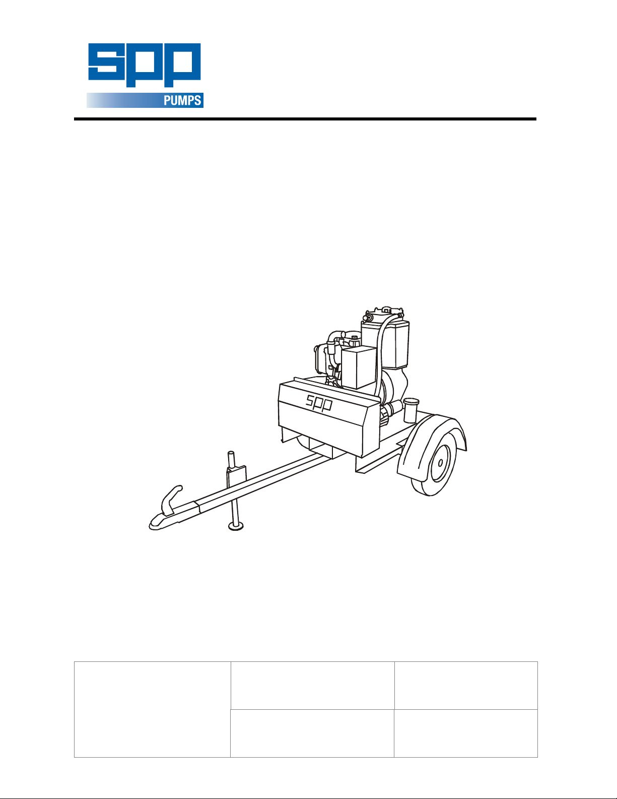
AUTOPRIME ACE RANGE
CENTRIFUGAL PUMP
OPERATORS INSTRUCTIONS
AUTOPRIME
ACE RANGE
DIESEL DRIVEN
MOBILE PUMPS
SPP Pumps Limited
Crucible Close
Mushet Industrial Park
Coleford, Glos
ENGLAND
GL16 8PS
Telephone:
++44(0) 1594 832701
Fax:
++44(0) 1594 836300
Document No: W72-019E
Revision No: 4
Revision Note No: R 39552
Date Issued. August 2012
Produced at SPP Pumps
Limited, Coleford, England
Page 2
We
Of
SPP Pumps Limited
Crucible Close
Mushet Industrial Park
Coleford
Gloucestershire
England
GL16 8PS
Declare that:
Equipment:
Model/Type:
Serial Number:
in accordance with the following Directives:
MOBILE DIESEL DRIVEN CENTRIFUGAL PUMPS
ACE80 & ACE100
As shown on the Pump Nameplate
DECLARATION OF
CONFORMITY
Sound Level (dB)
Pump Model Measured Guaranteed LWA
ACE80 106 109
ACE100 106 109
2000/14/EC- Guaranteed sound power level.
The conformity assessment procedure followed was in
according with ANNEX V of the Directive
2004/108/EC
2006/42/EC
2000/14/EC
have been designed and manufactured to the following specifications:
EN 809:1998+A1:2009
EN 12162: 2001
EN 292-2: 1991
EN 61000-6-4: 2001
EN 61000-6-1: 2001
EN 3744: 1995
We hereby declare that the equipment named above has been designed to comply with the relevant sections
of the above referenced specifications. The units comply with all essential requirements of the Directives
The Electromagnetic Compatibility Directive and its amending directives
The Machinery Directive and its amending directives
The Noise Emissions Directive and its amending directives
Liquid pumps – Safety requirements – Proceedure for hydrostatic testing.
Safety of Machinery- Basic concepts, general principles for design.
Electromagnetic compatibility (EMC). Generic standards. Emission standard
for industrial environment.
Electromagnetic compatibility (EMC). Generic standards. Immunity for
residential, commercial and light-industrial environments.
Acoustics- Determination of sound power levels of noise sources using sound
pressure- Engineering method in an essentially free field over a reflecting
plane
Pump and pump unit for liquids – common safety requirements
Signed:
Name: John Hollins
Position: Engineering Manager - Authorised to sign on behalf of SPP Pumps Limited
Mushet Industrial Park, Coleford, Gloucestershire, England, GL16 8PS
Date: 12 February 2010
W72-019E
A copy of this certificate has been submitted to the European Commission and UK Authority
Our policy is one of continuous improvement and we reserve the right to alter specifications at any time
Page 2 of 12
Page 3

Operators Instructions for
ACE80/100 Diesel Driven Centrifugal Pumps
Manual No/Rev
W72-019E / 4
CONTENTS
1. INTRODUCTION.............................................. 4
2. SERIAL NUMBER ........................................... 4
3. SAFETY PRECAUTIONS ................................ 5
3.1 Safety Symbols ................................................................. 5
3.2 Pump Safety Precautions ................................................. 5
4. HANDLING & TRANSPORT ........................... 5
4.1 Lifting ................................................................................ 5
4.2 Road Trailer Version ......................................................... 5
4.3 Trailer or Wagon Carriage ................................................ 5
5. OPERATING INSTRUCTIONS ........................ 6
5.1 Before Starting .................................................................. 6
5.2 Starting ............................................................................. 6
5.3 After Starting ..................................................................... 6
5.4 Stopping ............................................................................ 6
6. PUMP MAINTENANCE CHART ...................... 7
7. MAINTENANCE INSTRUCTIONS ................... 7
7.1 Mechanical Seal Oil Reservoir .......................................... 7
7.2 Drive Belt Adjustment ....................................................... 7
7.3 Mechanical Seals .............................................................. 7
7.4 Mechanical Seal Removal ................................................ 7
7.5 Mechanical Seal Assembly ............................................... 8
7.6 Non-Return Valve ............................................................. 8
7.7 VACUUM PUMP ............................................................... 8
7.8 Vacuum Pump Air Filter .................................................... 8
7.9 Valve Gear ........................................................................ 8
8. FAULT FINDING GUIDE ................................. 9
9. TECHNICAL DATA ........................................ 10
10. SPARES & SERVICE .................................... 12
Page 4
Manual No/Rev
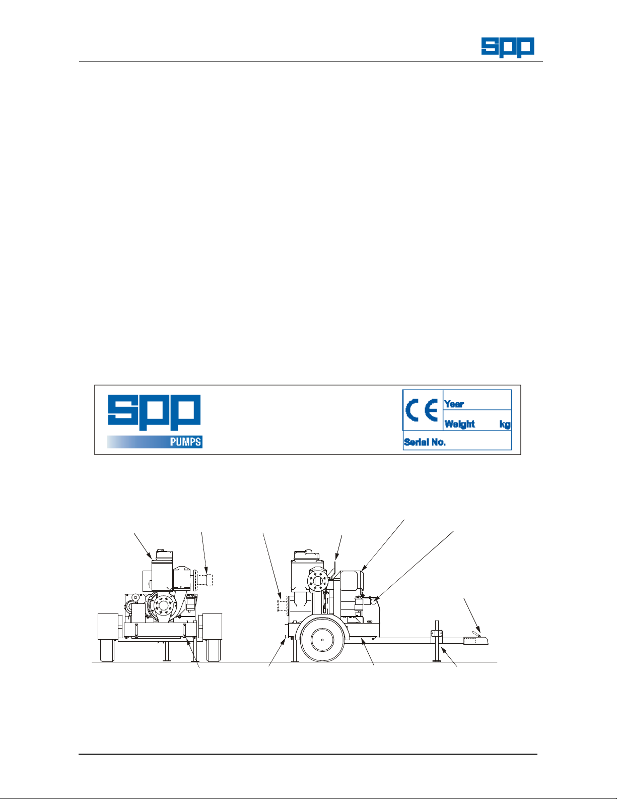
LIFTING
KEY
MOUNTING
STAND
DELIVERY
SUCTION
PRIMING
ENGINE
TANK
W72-019E / 4
ACE80/100 Diesel Driven Centrifugal Pumps
1. INTRODUCTION
The purpose of this handbook is to provide
operating guidelines and routine maintenance
instructions for the SPP AUTOPRIME ACE
Range of mobile diesel engine driven pumps.
Instructions and statements contained within
this handbook are given with our best
intentions and are correct at the time of
compilation. They are subject to alteration at
any time.
These pumps are most commonly supplied
mounted on 2 wheel road trailers but can also
be supplied skid mounted, or as a pump unit
for customer’s to mount on a suitable chassis
or foundations.
ACE pumps are primed by a 25cfm vacuum
pump and are driven by a close coupled, aircooled diesel engine.
Crucible Close, Mushet Industrial Park,
Coleford, Gloucestershire, ENGLAND,
ACE Range Pump Components
TANK
BAUER
Operators Instructions for
This Handbook covers the following pumps:
ACE80
driven by a Hatz 1D90 diesel engine mounted
on a fuel tank and road trailer or skid. This
unit is fitted with 3” Bauer hose connections.
ACE100
pump driven by a Hatz 1D90 diesel engine
mounted on a fuel tank and road trailer or
skid. This unit is fitted with 4” Bauer hose
connections.
2. SERIAL NUMBER
The serial number plate is attached to the
unit on the side of the priming tank.
This serial number must be quoted in any
enquiry for spares or service.
Where required, a trailer registration plate is
fitted to the front of the unit as required by
local regulations and the VIN number is
stamped on the fuel tank.
SPP Pumps Limited
GL16 8PS
Tel: +44(0)1594 832701
Fax: +44(0)1594 836300
BAUER
EYE
– An automatic priming mobile pump
– An automatic priming mobile
START
TOW
HITCH
LIGHTING BOARD
Our policy is one of continuous improvement and we reserve the right to alter specifications at any time
Page 4 of 12
FUEL
JACK
Page 5

Operators Instructions for
ACE80/100 Diesel Driven Centrifugal Pumps
3. SAFETY PRECAUTIONS
3.1 Safety Symbols
Safety instructions within this manual are
marked with the following symbols:
This symbol refers to general mechanical
aspects of safety.
This symbol refers to electrical safety.
ATTENTION
3.2 Pump Safety Precautions
apply to all the following:-
2.2.1
2.2.2
2.2.3
2.2.4
2.2.5
2.2.6
2.2.7
2.2.8
2.2.9
This symbol gives warning of a hazard
to the pump itself, which in turn could
cause a risk to personal safety.
ATTENTION
Hot surfaces and moving parts are guarded
to protect you. If these guards are removed
for maintenance, they must be replaced
before starting the pump.
Never insert anything into the pump casing
whilst the pump is running with the suction
and delivery hoses disconnected.
Collapsible hoses must not be used on the
suction side of the pump
Where the standard Bauer connections are
not used, use all pump flange holes to fit
suction and delivery hose connections.
Do not lift with fork of fork lift truck under the
fuel tank. Never lift with suction or delivery
hoses attached. The increased weight of
these items may cause lifting gear failure.
Always lift pump sets vertically by the lifting
eye. Check the condition of the lifter bracket
at regular intervals.
Check the type of liquid being pumped
before working on pump ends. Residues
could be hazardous to your health. If in
doubt flush out with clean water before work
commences.
Personnel working on the pump unit must
always wear clean correctly fitting clothing
and safety footwear. Clothing impregnated
with oil or fuel can constitute a health hazard
through prolonged contact with the skin and
may also constitute a fire hazard.
Always allow adequate ventilation for diesel
engines. Be aware of fire risks from items
such as exhaust pipes and silencers. Never
place flammable items around the unit.
Manual No/Rev
W72-019E / 4
2.2.10
When working near to the pump or in a
confined space with the pump running
personal ear protection is recommended.
4. HANDLING & TRANSPORT
4.1 Lifting
The central lifting eye is designed for lifting
only the pump unit as supplied by SPP
Pumps Limited. Due to the additional weight
of skid-mounted units, these may be fitted
with alternative lifting points and fork-lift truck
slots on the skid.
The central lifting eye is suitable only for
vertical lifting and must not be used to
pull the unit sideways.
4.1.1
Check the condition of the central lifting eye
or bracket before use.
4.1.2
Do NOT use a lift truck with forks under the
fuel tank and do NOT lift with the hoses
attached.
4.1.3
Never allow the unit to be subject to a
‘snatch’ loading.
4.1.4
Control the unit while lifting to prevent
swinging and keep personnel away from the
area below the unit and the immediate area.
4.2 Road Trailer Version
There is provision for a lighting board to be
fitted to the rear of the unit. Place the
lighting board in the two brackets and insert
pins to retain the lighting board in place.
4.3 Trailer or Wagon Carriage
Transportation on a trailer or wagon will
require the unit to be roped or strapped
down. On the road trailer mounted units, set
the unit level with the front and rear prop
stands lowered and clamped. Place ropes
or straps over the chassis to hold the unit in
place. Do NOT place ropes or straps over
the engine or the pump unit and ensure that
ropes or straps do not come into contact with
controls, switches, taps or other vulnerable
parts.
Page 6

Manual No/Rev
W72-019E / 4
ACE80/100 Diesel Driven Centrifugal Pumps
Operators Instructions for
5. OPERATING INSTRUCTIONS
5.1 Before Starting
5.1.1
Read this Handbook carefully.
5.1.2
Level the unit and jack or chock to prevent
movement in use.
5.1.3
Check the engine fuel and lubricating oil
levels. Top up as necessary.
5.1.4
Check the mechanical seal oil level using
the dipstick fitted to the filler plug.
5.1.5
Check the vacuum pump drive belt is
correctly tensioned.
5.1.6
Starting:- Ensure that the battery is charged
and ready for use.
5.1.7
Check that air inlets are unobstructed and
that the cylinder vanes are free from debris.
5.1.8
Check that the discharge non-return valve
is seating properly and that there is no
debris in the ball chamber that may prevent
correct operation.
5.1.9
Select and fit a suitable strainer for the job
in hand. Note that most ‘off the shelf’
strainers are for general purpose use. As
such they may not protect the pump against
oversize solids. For applications where
stones, etc., may be drawn in, then a
strainer with holes slightly smaller than the
pump handling capacity must be employed.
Refer to the Technical Data section for
details.
5.1.10
Connect suction and delivery hoses making
sure that there are no sharp bends in the
lines. Where the hoses pass over sharp
edges or abrasive surfaces ensure that they
are protected by suitable means to prevent
chafing. Ensure that the suction hose end
is fully submerged.
5.1.11
Check that the surge control valve is fully
screwed in. This is the large indented nut
surrounding the surge control valve knob on
the top of the priming tank.
5.2 Starting
5.3 After Starting
5.3.1
The pump will prime automatically once the
suction hose is submerged. If the pump
fails to prime refer to the fault finding guide.
(Section 8)
5.3.2
If the pump continually snores, gradually
release the surge control valve until the
vibrations reduce.
5.4 Stopping
5.4.1
Read the manufacturer’s instructions for the
Hatz engine in conjunction with the
following:-
5.4.2
Turn the keyswitch to the ‘Off’ position.
5.4.3
Open the volute cock to drain the volute.
Close after draining is complete. This must
be done before removing the suction and
delivery hoses.
5.4.4
When you take the pipes off there is a
chance that there will still be water in the
pipes so caution is advised.
5.2.1
Read the manufacturer’s instructions for the
Hatz engine in conjunction with the
following:
5.2.2
Push the decompressor lever(s) to the ‘Run’
position.
5.2.3
Turn the keyswitch to the ‘Start’ position
5.2.4
Release the keyswitch once the engine has
fired and got away.
Our policy is one of continuous improvement and we reserve the right to alter specifications at any time
Page 6 of 12
Page 7

Operators Instructions for
FORCE
LOCKING
NUT
DEFLECTION
BOLT
Manual No/Rev
ACE80/100 Diesel Driven Centrifugal Pumps
6. PUMP MAINTENANCE CHART
For engine maintenance periods refer to the engine operators handbook supplied with this manual.
PERIOD TASK
Daily Visually check for leaks.
Check for vibration.
Check the mechanical seal oil level and top up as required.
Weekly or
100 hrs
6 monthly
or 1500 hrs
Annually or
6000 hrs
The above schedule is given for guidance but site operating conditions may override the suggested
maintenance intervals
.
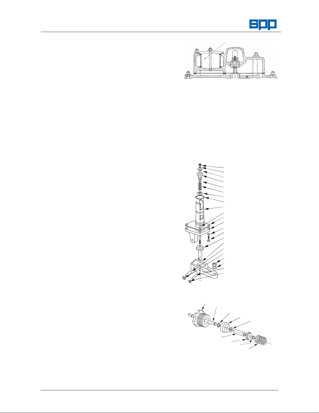
7. MAINTENANCE INSTRUCTIONS
7.1 Mechanical Seal Oil Reservoir
Maintain the oil level between the maximum
and minimum levels marked on the dipstick.
7.2 Drive Belt Adjustment
7.2.1
Remove guard.
7.2.2
Slacken the locking nut and the retaining
bolt, rotate the tensioner to adjust the
tension of the belt. Tighten the locking nut
and the retaining bolt and check the tension
thus:
RETAINING
7.2.3
V Belt tension is correct when the deflection
is 4mm with a force of 1.5kg applied at the
centre of the longest run.
Note: DO NOT OVERTIGHTEN BELTS
UNDER ANY CIRCUMSTANCES.
7.3 Mechanical Seals
Check all fastener security.
Check the condition of the lifter bracket/frame and check the security of attachment to
the unit.
Check tension of vacuum pump drive belt.
Check reflux ball is sealing on its seat.
Check and if necessary renew vacuum pump drive belt.
Dismantle and clean valve gear, tank, connecting pipes and priming tank.
Change mechanical seal oil.
Check vacuum pump blade condition
are never run dry. Immediate seal failure
will result.
7.3.2
Any contamination of the fluid should be
investigated immediately. Should a large
loss of fluid be experienced then the pump
must be stopped immediately.
7.3.3
Replacement of the seals is considered a
workshop operation where higher standards
of cleanliness can be maintained and the
specialised tooling required is more readily
available.
7.4 Mechanical Seal Removal
7.4.1
Remove the Tee piece and priming tank,
place oil tray under mechanical seal oil
drain plug to drain oil.
7.4.2
Remove the non-return valve and volute to
access the impeller. Unscrew impeller anticlockwise with the aid of a mallet until
undone, note the number of shims fitted
behind and retain for reuse.
7.4.3
Once the impeller is removed, remove the
rotating part of the primary mechanical seal
Belt Tensioning
and remove rear wear plate. Then press
the seat out of the back wearplate.
7.4.4
Remove the circlip and washer off the shaft.
Then remove the secondary mechanical
seal and engine adaptor plate. Then press
out the seat.
7.4.5
Check the condition of the ’O’-rings and
replace if necessary.
W72-019E / 4
7.3.1
Ensure that the coolant/lubricant level is
maintained. It is imperative that the seals
Page 8
Manual No/Rev
AIR FILTER
25PTFLTA
M4 SELF LOCK NU T
MAIN INLET VALVE
AIR OUTLET VALVE
M10 STARLOCK WASHER
KNOB (NOT SHOWN)
SPRING
W72-019E / 4
ACE80/100 Diesel Driven Centrifugal Pumps
7.5 Mechanical Seal Assembly
7.5.1
Assemble the engine adaptor plate on to
the engine and press the stationary seat in
to the plate ensuring not to damage the
face. Replace the rotating part of the seal
preferably with SPP tool no 22743 and push
it up until the circlip groove is exposed
behind the seal. Replace the circlip washer
and circlip and ensure the mechanical seal
is securely in place and against the washer.
7.5.2
Assemble the back wear plate onto the
engine adaptor and press the mechanical
seal seat into the wear plate. Replace the
rotating part of the seal so that the faces
meet. Assemble the impeller with the
reused shims and tap with a mallet to
tighten.
7.5.3
Assemble the non-return valve and volute.
Ensure that the impeller still moves without
touching the wearplate. Measure the
clearance between the wearplates and the
impeller and if they do not fall within the
range specified in the table in Section 9,
then shim as necessary to avoid loss of
efficiency.
7.5.4
Replace the Tee piece and priming tank
and tighten mechanical seal oil plug. Add
oil as indicated on dipstick
7.6 Non-Return Valve
7.6.1
A ball type non-return valve is fitted to the
pump discharge.
7.6.2
The ball should be regularly checked for
freedom of movement and absence of
debris by inspection through the discharge.
7.6.3
The correct seating of the ball can be
checked through the delivery flange of the
valve body. The valve body should be
removed to check the seat for damage or
wear.
7.7 VACUUM PUMP
Vacuum pump overhaul is beyond the
scope of this manual. Should the vacuum
pump be suspect then it is recommended
that an exchange unit is fitted and the
suspect unit returned to the manufacturers
for examination.
Operators Instructions for
7.7.2
To remove the air filter undo the central nut
holding the air filter cover and remove to
expose the filter element.
7.9 Valve Gear
The valve assemblies are shown below.
The valves, seats and pins should be
checked regularly for wear or damage.
Worn parts should be replaced. The main
valve is located on the underside of the top
cover.
Air Filter Location
NYLON WASHER
AIR INLET VALVE
M4 WASHER
SPRING
DIAPHRAGM
O RING
VALVE SEAT
VALVE ROD
GASKET
FULCRUM BRACKET
M6 WASHER
M6 CAPSCREW
FULCRUM ARM
FULCRUM PIN
M8 SELF LOCK NUT
M8 WASHER
VALVE SUPPORT PIN
M6 STARLOCK WASHER
Main Valve Assembly
VALVE SEAT
VALVE SPINDLE
KLIP RING
VALVE
M8 WASHER
7.8 Vacuum Pump Air Filter
7.7.1
Air filters are located in the valve cover of
the primary tank and should be checked
SPRING RETAINER
Surge Control Valve Assembly
KLIP RING
regularly for cleanliness, distortion or
damage see the figure below. Replace if
distorted or damaged.
Our policy is one of continuous improvement and we reserve the right to alter specifications at any time
Page 8 of 12
Page 9

ACE80/100 Diesel Driven Centrifugal Pumps
8. FAULT FINDING GUIDE
Pump Fails to Prime
Are
NO
all plugs
tight?
NO YES
Operators Instructions for
Disconnect suction hose
Blank off suction entry
Fit vacuum gauge
Reading
between
85 - 89 .5 kpa
(28.5 0 30 ft H20)?
Manual No/Rev
W72-019E / 4
Check vertical
suction lift
Rectify &
re-test
Fit vacuum gauge
(28.5 0 30 ft H20)?
NO
Is belt drive
tension OK?
YES
Test the Vacuum
Pump directly
Reading
between
85 - 89 .5 kpa
NO
YES
Rectify YES
Rectify NO
Is
Reflux Valve
Ball seating
properly?
YES
Is Vacuum
Pump filter
blocked?
NO
Is Main
Valve float
gear free and
intact?
YES
Move
Pump
YES
NO
Rectify
Lift< or =
8.53m (28ft) for
ACE80/100
NO
Are hoses
leaking, collapsed
or blocked?
NO
Is intake
blocked?
NO
Is impeller
blocked?
YES
Rectify
YES
Rectify
YES
Rectify
Rectify
YES
Excessive wear.
Remove Vacuum
Pump & either
overhaul or fit new or
exchange pump
NO
Rectify
YES
Is pump
casing free from
holes?
ACE80-100 Fault Finding Chart
Are all
joints sound &
leak free?
YES
Check impeller wear
plate clearances
and rectify
NO
Rectify
Is the
pump or NRV
blocked or
damaged?
NO
YES
Rectify
Page 10

Manual No/Rev
Weight
(With full fuel tank)
470 Kg
1036 lbs
Hitch Weight Dry
32 Kg
70 lbs
2320mm
135mm
1
2
3
3
m
m
91.34”
81.3”
5.31”
4
8
.
5
4
”
W72-019E / 4
ACE80/100 Diesel Driven Centrifugal Pumps
Operators Instructions for
9. TECHNICAL DATA
CHARACTERISTICS ACE80/100 ACE80/100
Vacuum Pump 25 ft3/min 25 ft3/min
Solids Handling Capability 40 mm Diameter 1.5” Diameter
Engine Type Hatz 1D90 Air cooled Hatz 1D90 Air cooled
Fuel Tank Capacity 55 Litres 14.5 Gal (US)
Approx. Running Time On Full Tank 24 Hours 24 Hours
Impeller Back Plate Clearance 0.5 - 1.5mm 0.019 - 0.059”
Impeller Front Plate Clearance 0.38 - 0.5mm 0.015 - 0.019”
Mechanical Seal Coolant/Lubricant Mobil Velocite Oil No. 6, Texaco Rando HD10 Or equivalent
Weight Dry (No fuel in tank) 420 Kg 925 lbs
Towing Hitch Types Towing Eye or Ball Hitch
Flange Drilling PN16 is standard, ANSI flange drilling is optional
1363mm
53.66”
4.72”
2065mm120mm
Note - These dimensions are approximate and may vary to suit the selected customer options.
Our policy is one of continuous improvement and we reserve the right to alter specifications at any time
Page 10 of 12
Page 11

Operators Instructions for
ACE80/100 Diesel Driven Centrifugal Pumps
Manual No/Rev
W72-019E / 4
Page 12

Manual No/Rev
W72-019E / 4
ACE80/100 Diesel Driven Centrifugal Pumps
Operators Instructions for
10. SPARES & SERVICE
SPP Pumps operate a comprehensive Spares and Service support network throughout the world, and
can be contacted as follows:
SPARES & SERVICE Telephone: **44 (0) 1189 323123
For spare parts, supply only. Ask for - Spares Dept.
For breakdowns, spare parts and on-site fitting, pump installation and
commissioning, and service contracts. Ask for - Service Dept.
For breakdowns outside office hours. Telephone : **44 (0) 1491 201613
Spares & Service Office
SPP Pumps Limited General Fax line: **44 (0) 1189 323302
1420 Lakeview
Arlington Business Park
Reading, Berkshire Direct Fax line: **44 (0) 1189 303259
RG7 4SA
ENGLAND
Copies of this manual are available from the SPP Pumps Limited Spares & Service Department by
quoting the manual reference number and the relevant revision number.
ENGINE OPERATORS HANDBOOK
The specific engine operator’s handbook from the manufacturer is included within the pump
documentation pack.
---“---
Your Local Supplier’s contact details may be shown here:
Our policy is one of continuous improvement and we reserve the right to alter specifications at any time
Page 12 of 12
 Loading...