

Page 1
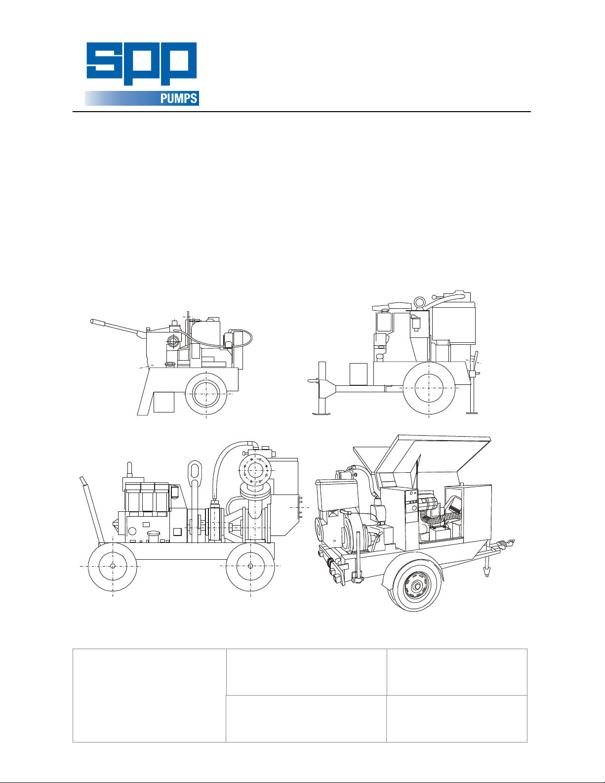
AUTOPRIME PRODUCT
50_7514A
AC50 & AC75
100M & 150M
AC80 & AC100
OPERATORS HANDBOOK
AUTOPRIME
DIESEL DRIVEN
PUMPSETS
100M_31A
SPP Pumps Ltd.
Crucible Close
Mushet Industrial Park
Coleford
Gloucestershire
ENGLAND
GL16 8PS
Telephone:
01594 832 701
Fax:
01594 836 300
8010019A
A
0
3
_
M
0
0
1
Document No: . W72-002E
Revision No: .................. 12
Revision Note No: . R 39552
Date Issued . August 2012
Produced at SPP Pumps,
Coleford, England
Page 2

We SPP Pumps Limited
Sound Level (dB)
Pump Model Measured Guaranteed LWA
AC50 & AC75 105 108
AC80 & AC100 106 109
100M & 150M 103 106
Of Crucible Close
Mushet Industrial Park
Coleford
Gloucestershire
England
GL16 8PS
Declare that:
Equipment: DIESEL DRIVEN CENTRIFUGAL PUMPS
Model/Type: AC50 & AC75, AC80 & AC10, 100M & 150M
Serial Number: As shown on the Pump Nameplate
in accordance with the following Directives:
Cross 2000/14/EC- Guaranteed sound power level.
The conformity assessment procedure followed was in
according with ANNEX V of the Directive.
DECLARATION OF
CONFORMITY
2004/108/EC The Electromagnetic Compatibility Directive and its amending directives
2006/42/EC The Machinery Directive and its amending directives
2000/14/EC The Noise Emissions Directive and its amending directives
have been designed and manufactured to the following specifications:
EN 809:1998+A1:2009 Pump and pump unit for liquids – common safety requirements
EN 12162: 2001 Liquid pumps – Safety requirements – Proceedure for hydrostatic testing.
EN 292-2: 1991 Safety of Machinery- Basic concepts, general principles for design.
EN 61000-6-4: 2001 Electromagnetic compatibility (EMC). Generic standards. Emission standard
for industrial environment.
EN 61000-6-1: 2001 Electromagnetic compatibility (EMC). Generic standards. Immunity for
residential, commercial and light-industrial environments.
EN 3744: 1995 Acoustics- Determination of sound power levels of noise sources using sound
pressure- Engineering method in an essentially free field over a reflecting
plane
We hereby declare that the equipment named above has been designed to comply with the relevant sections
of the above referenced specifications. The units comply with all essential requirements of the Directives
Signed:
Name: John Hollins
Position: Engineering Manager - Authorised to sign on behalf of SPP Pumps Limited
Mushet Industrial Park, Coleford, Gloucestershire, England, GL16 8PS
Date: 12 February 2010
W72-002E
A copy of this certificate has been submitted to the European Commission and UK Authority
Our policy is one of continuous improvement and we reserve the right to alter specifications at any time
Page 2 of 16
Page 3

Operators Handbook for
Diesel Driven Pump Sets
Manual No/Rev
W72-002E / 11
CONTENTS
1. INTRODUCTION .................................................................................... 4
1.1 PUMP DESIGNATIONS ........................................................................................... 4
1.2 PUMP TYPES .......................................................................................................... 4
2. SAFETY PRECAUTIONS ...................................................................... 6
2.1 SAFETY SYMBOLS ................................................................................................. 6
2.2 PUMP SAFETY PRECAUTIONS ............................................................................. 6
3. TRANSPORT ......................................................................................... 6
3.1 ROAD TOWED ........................................................................................................ 6
3.2 TRAILER OR WAGON CARRIAGE ......................................................................... 6
3.3 MOVEMENT BY LIFTING ........................................................................................ 6
4. SERIAL NUMBER ................................................................................. 7
5. OPERATING INSTRUCTIONS .............................................................. 7
5.1 BEFORE STARTING ............................................................................................... 7
5.2 STARTING ............................................................................................................... 7
5.2.1 Canopy sets ................................................................................................... 7
5.2.2 Open sets ...................................................................................................... 8
5.3 AFTER STARTING .................................................................................................. 8
5.4 STOPPING ............................................................................................................... 8
5.4.1 Canopy sets ................................................................................................... 8
5.4.2 Open sets ...................................................................................................... 8
6. PUMP MAINTENANCE CHART ............................................................ 9
7. MAINTENANCE INSTRUCTIONS ....................................................... 10
7.1 COALESCER (100M, 150, 150M, 200) ................................................................ 10
7.2 OIL RESERVOIR (AC50, AC75, AC80 & AC100).................................................. 10
7.2.1 AC50 & AC75 .............................................................................................. 10
7.2.2 AC80 & AC100 .............................................. Error! Bookmark not defined.
7.3 COUPLING (open coupled sets) ............................................................................ 10
7.4 DRIVE BELT ADJUSTMENT ................................................................................. 10
7.5 PUMP VACUUM PRESSURE SEAL ..................................................................... 11
7.5.1 Close coupled AC50, AC75, AC80 and AC100 pumps ............................... 11
7.5.2 Open coupled pumps .................................................................................. 11
7.6 MECHANICAL SEALS ........................................................................................... 12
7.7 NON-RETURN VALVE .......................................................................................... 12
7.8 PUMP BEARINGS (Open coupled pump sets only) .............................................. 12
7.9 VACUUM PUMP .................................................................................................... 12
7.10 VACUUM PUMP AIR FILTER .............................................................................. 12
7.10.1 Standard air filter ....................................................................................... 12
7.10.2 High Capacity Air Filter .............................................................................. 13
7.11 VALVE GEAR ....................................................................................................... 13
7.12 SURGE CONTROL VALVE ................................................................................. 14
8. FAULT FINDING GUIDE ..................................................................... 15
9. TECHNICAL DATA .............................................................................. 16
10. SPARES & SERVICE ........................................................................ 16
11. COUPLING DETAILS (where applicable) ........................................ 16
12. ENGINE OPERATORS HANDBOOK ................................................ 16
Our policy is one of continuous improvement and we reserve the right to alter specifications at any time
Page 3 of 16
Page 4
Manual No/Rev
Pump
W72-002 / 11
Operators Handbook for
Diesel Driven Pump Sets
1. INTRODUCTION
The purpose of this handbook is to lay down
operating guidelines and simple routine
maintenance for the AUTOPRIME range of
diesel engine driven mobile pump sets fitted
with vacuum pumps.
Instructions and statements contained within
this handbook are given with our best
intentions and are correct at the time of
compilation. They are subject to alteration at
any time.
1.1 PUMP DESIGNATIONS
These are derived from the nominal size of the
pump discharge and suction pipes with prefix
and suffix letters to signify:
A = Air Cooled
C = Close Coupled
M = High Capacity Pump Design
e.g. An AC100 pump set has an air cooled
engine, is close coupled and has
100mm (4”) bore suction and delivery
connections, and -
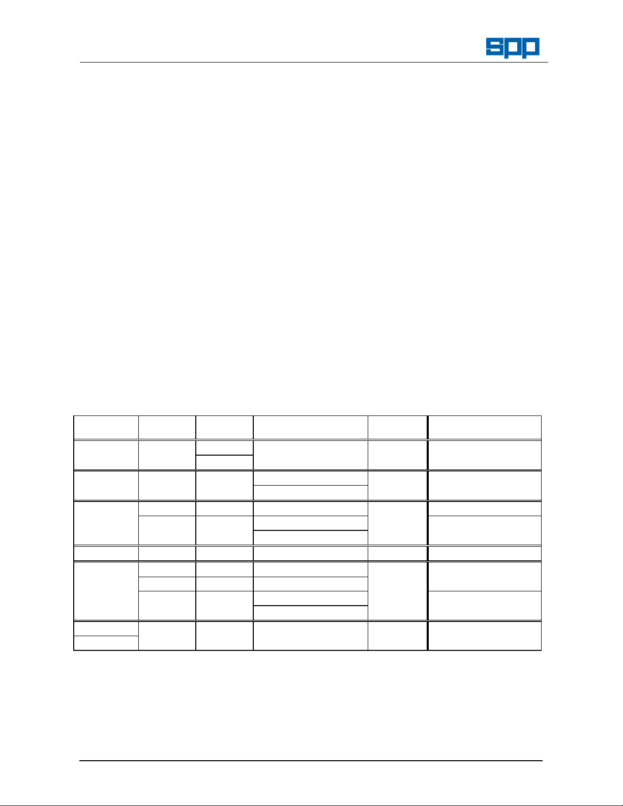
1.2 PUMP TYPES
Pump Type Driver Starting Trailer
A 100M pump set is a 100m (4”) high
capacity pump. Note that these can be
supplied in open or canopied form with
either a four wheeled site trailer or two
wheeled road trailer chassis.
Vacuum pumps are supplied to suit pumping
requirements, there are four main sizes:-
10.2m3/hr (6ft3/min)
30.6m3/hr (18ft3/min)
42.6m3/hr (25ft3/min)
102m3/hr (60ft3/min).
This manual covers the range of units shown
below. Note that some units can be fitted with
either vacuum pressure seals or tandem
mechanical seals. Ensure that the correct
instructions and diagrams are being referred to
for the particular unit under consideration.
Other order specific components may also be
fitted. If in doubt over any item consult the unit
supplier.
Vacuum
Features
AC50 & AD1 Hand 2 wheel site -hand 6 cfm Close coupled
AC75 Electric
AC80 TR1 Electric 2 wheel site - towed 18 cfm Close coupled
AC100 2 wheel road - towed
100M TR2 Electric 4 wheel site - towed 25 cfm
LPW3 Electric 4 wheel site - towed Noise reducing canopy
2 wheel road - towed
150 TS3 Hand 2 wheel site towed 60 cfm Bronze internals/coated
150M TS3 Hand 2 wheel site towed 60 cfm Bronze internals
TR3 Hand 4 wheel site towed
LPW4 Electric 4 wheel site towed Noise reducing canopy
2 wheel road - towed
200 CD4 Electric 4 wheel site - towed 25 cfm
200 60 cfm
Our policy is one of continuous improvement and we reserve the right to alter specifications at any time
Page 4 of 16
Page 5
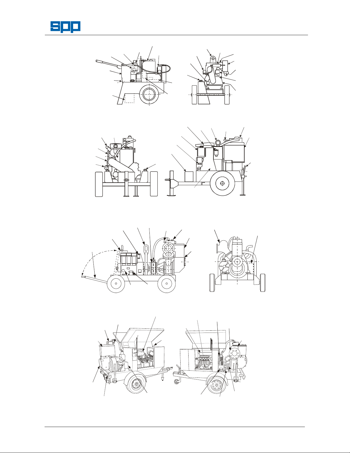
Operators Handbook for
EXHAUST
SILENCER
LUB OIL
DIPSTICK
(on underside
of filler cap)
VACUUM
LUB OIL
RESERVOIR
SILENCER
ENGINE
FILTER
UNIT
ENGINE
PRIMING
CONTROL
SUCTION
AIR
FILLERS
ENGINE
PRIMING
VALVE
COVER
CONTROL
UNIT
ENGINE
NON RETURN
BATTERY
REFLUX BOX
(NON RETURN
PUMP VACUUM
PRESSURE SEAL
AIR
COALESCER
Diesel Driven Pump Sets
DELIVERY
FLANGE
(on far side)
PRIMARY
TANK
SUCTION
FLANGE
BATTERY
(electric start
only)
50_75GAB
MINI BALL
VALVE
(in line)
Figure 0-1 AC50 Pump
EXHAUST
DELIVERY
FLANGE
VACUUM
PUMP
VACUUM
PUMP
SILENCER
VALVE
COVER
ENGINE
VACUUM
PUMP
KEYSWITCH
& RUNNING
HOUR RECORDER
(electric start only)
(2” Bauers)
VACUUM
PUMP OIL
RESERVOIR
ENGINE OIL
FILLER
BATTERY
FUEL
(both sides)
PUMP
ENGINE
LUB OIL
FILTER
FUEL
TANK
FILLER
STARTER
MOTOR
(if fitted)
and AC75 Pump
FUEL
FILTER
FILTER
LIFTER
UNIT
LIFTER
VACUUM
PUMP
(3" Bauers)
SURGE
VALVE
AIR
CLEANER
FUEL
STOP
LEVER
Site Trailer
VALVE
COVER
TANK
Manual No/Rev
W72-002E / 11
FLANGE
8010023A
Figure 0-2 AC80 Pump
(3" Bauers)
and AC100 Pump
ENGINE OIL
DIPSTICK
(4" Bauers)
Site Trailer
VACUUM
PUMP
FUEL
FILLER
SURGE
VALVE
TANK
SUCTION
FLANGE
VALVE
100M_32A
EXHAUST
SILENCER
PIVOTING
TOWBAR
FUEL
FILTER
LIFTER
ENGINE
DIPSTICK
Figure 0-3 100M-25 Pump and 150M-60 Pump - Site Trailer - Open Set
ENGINE OIL
FILLER AND
DIPSTICK
EXHAUST
VACUUM
PUMP
DELIVERY
FLANGE
VALVE)
VALVE
COVER
PRIMING
TANK
SURGE
CONTROL
VALVE
FILTER
ENGINE
COOLANT
SUCTION
FLANGE
COALESCER
VENT
100M_33A
VACUUM
PUMP
FUEL
FILLER
FUEL
GAUGE
Figure 0-4 100M-25 Pump and 150M-60 Pump - Road Trailer. - Canopied Set
Our policy is one of continuous improvement and we reserve the right to alter specifications at any time
Page 5 of 16
Page 6

Manual No/Rev
W72-002 / 11
2. SAFETY PRECAUTIONS
2.1 SAFETY SYMBOLS
Safety instructions within this manual are
marked with the following symbols:
This symbol refers to general mechanical
aspects of safety.
This symbol refers to electrical safety.
ATTENTION
This symbol gives warning of a hazard
to the pump itself, which in turn could
cause a risk to personal safety.
Operators Handbook for
Diesel Driven Pump Sets
2.2.8
2.2.9
3. TRANSPORT
3.1 ROAD TOWED
Always allow adequate ventilation for
diesel engines. Be aware of fire risks
from items such as exhaust pipes
and silencers. Never place
flammable items around the unit.
Collapsible hoses must not be used
on the suction side of the pump.
Lighting boards are provided for road
going trailers.
2.2 PUMP SAFETY PRECAUTIONS
ATTENTION
apply to all the following:-
2.2.1
Never insert anything into the pump
casing whilst the pump is running and
the suction or delivery hoses are
disconnected.
2.2.2
Moving parts are guarded to protect you.
Guards removed for maintenance must
be replaced before starting the pump.
2.2.3
If the supplied Bauer connections are
not utilised, then use all flange bolts
when fitting suction and delivery hoses.
2.2.4
Always lift pump sets vertically by the
lifting eye. Do not lift with the forks of a
fork truck under the fuel tanks. Never lift
with suction or delivery hoses attached.
The increased weight of these items
may cause lifting gear failure.
2.2.5
Check the condition and security of the
lifter frame or bracket at regular
intervals.
2.2.6
Check the type of liquid being pumped
before working on pump ends. Residues
could be hazardous to your health. If in
doubt flush out with clean water before
work commences.
2.2.7
Personnel working on the pump unit
must always wear clean, correctly fitting
clothing and safety footwear. Clothing
impregnated with oil or fuel can
constitute a health hazard through
prolonged contact with the skin and may
also constitute a fire hazard.
3.2 TRAILER OR WAGON CARRIAGE
Transportation on a trailer or wagon will
require the unit to be strapped or roped
down. Always strap/rope the unit around
the chassis - NEVER over the engine,
pump or canopy (if fitted).
Ensure that the straps/ropes do not
come into contact with any items
(switches, drain taps, etc..) which may
be vulnerable to damage during transit.
3.3
MOVEMENT BY LIFTING
ATTENTION
If the unit is moved by lifting then the
condition and security of the lifter must
be checked before use.
The lift must always be vertical on the
eye provided.
Never allow the unit to be subject to a
‘snatch’ loading.
Do not allow the unit to swing whilst
being lifted.
Keep people away from the area
underneath the lifted unit and the
immediate surrounding area.
Failure to observe any of the above
could result in personnel injury or death
due to failure of the lifting gear.
Our policy is one of continuous improvement and we reserve the right to alter specifications at any time
Page 6 of 16
Page 7

Operators Handbook for
SPP Pumps Limited
Reading, RG31 7SP
Tel: ++44(0)118 932 3123
Diesel Driven Pump Sets
Manual No/Rev
W72-002E / 11
4. SERIAL NUMBER
A serial number plate is attached to the unit on the side of the priming tank. This serial number must be
quoted in any enquiry for spares or service.
Type
ENGLAND
Fax: 118 932 3302++44(0)
5. OPERATING INSTRUCTIONS
5.1 BEFORE STARTING
5.1.1
Read this Handbook carefully.
5.1.2
Level the unit and jack or chock to
prevent movement in use.
5.1.3
Check the engine fuel and
lubricating oil levels. Top up as
necessary.
5.1.4
If mechanical seals are fitted check
ATTENTION
5.1.8
the reservoir coolant or lubricant
level.
5.1.5
Check the vacuum pump drive belt
is correctly tensioned.
5.1.6
Hand start engines:- Check that
the starting handle is serviceable.
Electric start engines:- Ensure that the
batteries are charged and ready for
use.
5.1.7
Radiator cooled engines:- Check
the coolant level and that the
radiator is free from any debris.
Note that these units are fitted with
‘puller’ fans and therefore it is the
external face of the radiator which
may become blocked.
Air cooled engines:- Check that air inlets
are unobstructed and that the
cylinder vanes are free from debris.
AC50, AC75, AC80 & AC100:Check oil levels in vacuum pump
reservoirs.
Other units:- Draw off any water from the
vacuum pump coalescer oil sump
via the tap in the side. Check the oil
level which should be level with the
underside of the cap.
Our policy is one of continuous improvement and we reserve the right to alter specifications at any time
5.2 STARTING
Page 7 of 16
Nett
Serial No.
5.1.9
Check that the discharge non return
valve is seating properly and that
there is no debris in the ball
chamber that may prevent correct
operation.
5.1.10
Select and fit a suitable strainer for
the job in hand. Note that most ‘off
ATTENTION
the shelf’ strainers are for general
purpose use. As such they may not
protect the pump against oversize
solids. For applications where
stones, etc., may be drawn in, then
a strainer with holes slightly smaller
than the pump handling capacity
must be employed. Refer to the
Technical Data section for details
on specific pumps.
5.1.11
Connect suction and delivery hoses
making sure that there are no sharp
bends in the lines. Where the
hoses pass over sharp edges or
abrasive surfaces ensure that they
are protected by suitable means to
prevent chafing. Ensure that the
suction hose end is fully
submerged.
5.1.12
AC50 & AC75: Ensure that the mini
ball valve connecting the suction
line to the top cover of the pump is
in the open position (screwdriver
slot aligns with the axis of the
body).
Other units: Check that the surge control
valve is fully screwed in. This is the
large indented nut surrounding the
surge control valve knob on the top
of the priming tank.
5.2.1 Canopy sets
The starting panel on these units is under the
right hand door (looking from the tow bar
end) and comprises:-
kg
Page 8

Manual No/Rev
W72-002 / 11
a) three position keyswitch (Off, 1, &
b) protection override push button
c) circuit breaker
d) hours run counter
e) four warning indicator lamps:: Charge
Oil pressure
Water temperature
Coalescer oil level
Turn the ignition switch to the '1' position.
All four warning lights will illuminate,
providing a check that all circuits are
healthy.
Press and hold the override push-button
whilst turning the keyswitch to the 'Start'
position. Release the keyswitch and pushbutton once the engine has fired and got
away. Do not keep the override pushbutton depressed for more than 5 seconds
after the engine is up to speed.
5.2.2 Open sets
Read the manufacturer’s instructions for
the specific engine in conjunction with the
following.
Hand start engines:-
1.
Push the decompressor lever(s) to the
‘Stop’ position.
2.
Ensure the stop/run lever is in the
‘Run’ position.
3.
Hand crank the engine as fast as
possible and move the decompressor
lever(s) to the run position while
continuing to crank briskly until the
engine starts.
4.
Remove the starting handle.
Electric start engines:-
1.
Push the decompressor lever(s) to the
‘Run’ position.
2.
Ensure the stop/run lever is in the
‘Run’ position.
3.
Turn the keyswitch to the ‘Start’
position whilst pressing the shutdown
override push button (if fitted).
4.
Release the keyswitch and push-button
once the engine has fired and got
away. Do not keep the override pushbutton depressed for more than 5
Our policy is one of continuous improvement and we reserve the right to alter specifications at any time
Start)
Operators Handbook for
Diesel Driven Pump Sets
5.3 AFTER STARTING
The pump will prime automatically once
the suction hose is submerged. If the
pump fails to prime refer to the fault
finding guide.
5.4 STOPPING
5.4.1 Canopy sets
Turn the keyswitch to the 'Off' position.
The unit will stop and the key can be
removed.
Open the volute cock to drain the volute.
Close after draining is complete.
5.4.2 Open sets
Read the manufacturer’s instructions for
the specific engine in conjunction with the
following:-
1.
ATTENTION
2.
ATTENTION
3.
1.
Page 8 of 16
seconds after the engine is up to
speed.
Turn the engine stopping lever to the
‘Stop’ position and hold until the engine
comes to rest. Never use the
decompressor lever(s) for this purpose
Turn the keyswitch to the ‘Off’ position.
Failure to turn the keyswitch off will
leave the running hour recorder
energised and counting which will
result in a flat battery. Note that turning
the keyswitch off does NOT stop the
unit.
Open the volute cock to drain the
volute. Close after draining is
complete.
Page 9

Operators Handbook for
Diesel Driven Pump Sets
Manual No/Rev
W72-002E / 11
6. PUMP MAINTENANCE CHART
For engine maintenance periods refer to the engine operators handbook at the back of this publication.
PERIOD PUMP SET TASK
Daily All units Visually check for leaks
Check for vibration
Mechanical seal
units
100M,
150, 150M,
& 200
Check mechanical seal coolant/lubricant level and top up as
required
Drain any water from coalescer, check oil level and top up as
required
Hand test bearing housing for any sign of temperature rise
Weekly or
100 hrs
Monthly
or 500
hrs
AC80 & AC100 Check oil level of vacuum pump reservoir
6 monthly
or 1500
hrs
Vacuum pressure
Mechanical seal
All units Check all fastener security
Check the condition of the lifter bracket/frame and check the
security of attachment to the unit
Check tension of vacuum pump drive belt
AC50 & AC75
100M,
150, 150M,
& 200
All units Check reflux ball is sealing on its seat
seal units
units
Check oil level of suction line reservoir
Remove primary tank assembly and check pump internals
for wear
Check valve gear - clean or renew filter element
Change coalescer sump oil
Clean coalescer sump oil filter mesh
Remove front cover and check pump internals for wear
Check valve gear - clean or renew standard filter element.
Check high capacity filter element.
Grease bearings
Check and if necessary renew vacuum pump drive belt
Dismantle and clean valve gear, tank and connecting pipes
Dismantle and clean pump vacuum pressure seal
Renew packing
Change mechanical seal coolant/lubricant
Annually
or 6000
hrs
100M,
The above schedule is given for guidance but site operating conditions may override the suggested
maintenance intervals.
Our policy is one of continuous improvement and we reserve the right to alter specifications at any time
All units Check vacuum pump blade condition
Check bearing condition
150, 150M,
& 200
Renew coalescer filter mesh
Page 9 of 16
Page 10

Manual No/Rev
Force (kg)
producing
‘X’)
AC75
AC
100
belt
Canopied
Low noise
units
link belt
W72-002 / 11
Operators Handbook for
Diesel Driven Pump Sets
1.
7. MAINTENANCE INSTRUCTIONS
7.1 COALESCER (100M, 150, 150M, & 200)
Check the oil level in the coalescer tank and
drain any water daily. The top of the oil
should be level with the underside of the filler
cap. Water is removed by means of the drain
tap fitted to the side of the coalescer sump.
The filter mesh is accessed by removing the
coalescer lid and must be cleaned regularly
by washing in petrol or a similar spirit. When
refitting ensure filter mesh is below exhaust
port. The oil feed pipe should be cleaned in a
similar manner and blown through with an air
line.
7.4 DRIVE BELT ADJUSTMENT
Figure 0-2 Belt tensioning
Pump
sets
AC50 &
AC80 &
Others Timing
Belt type Deflec-
‘X’mm
V belt 5 1.5
V-belt 4 1.5
(toothed)
tion
deflection
4 1.5
Figure 0-1 Coalescer detail
7.2 OIL RESERVOIR (AC50, AC75, AC80 &
AC100)
7.2.1 AC57 &AC75
Ensure that oil reservoir is always kept
topped up.
7.2.2 AC80 & AC100
Maintain the oil level between the
maximum and minimum levels marked
on the bottle.
7.3 COUPLING (open coupled sets)
Coupling details are provided at the back of
this manual.
PowerTwist
A section
1.6 1.5-2.0
To adjust belt tension, loosen the vacuum
pump holding nuts and slide the
vacuum pump outward. When the
correct belt tension is obtained retighten holding nuts. Ensure that the
pump drive is in line after tightening.
Link belt drives can be further adjusted by
removing links.
DO NOT OVERTIGHTEN BELTS UNDER
ATTENTION
ANY CIRCUMSTANCES.
For AC50, AC75, AC80 & AC100 pumps
fitted with V belts and other pumps
fitted with PowerTwist link belts, the
belts can be replaced by slackening the
vacuum pump holding down bolts. For
other pumps it is necessary to
disconnect the coupling to replace the
belts.
7.5
Our policy is one of continuous improvement and we reserve the right to alter specifications at any time
Page 10 of 16
Page 11

Operators Handbook for
Diesel Driven Pump Sets
PUMP VACUUM PRESSURE SEAL
The seal is product lubricated and therefore
requires only regular inspections of condition,
signified by rate of leakage, and eventual
replacement. To replace the packing:-
7.5.1 Close coupled AC50, AC75, AC80 &
AC100 pumps
1.
Ensure the volute is drained and
contains no harmful residues. A drain
tap is located on the bottom of the
volute.
2.
Disconnect the vacuum pump suction
line from the top of the priming tank
assembly. On AC80 and AC100 units
disconnect the back priming line.
3.
Remove the complete priming tank and
sump assembly from the volute. Note
the number of gaskets fitted between the
sump and volute. Examine their
condition and either replace or retain for
reuse
Manual No/Rev
W72-002E / 11
material is graphite impregnated
braided P.T.F.E.
7.
Place the packing into the holder
(see Figure 7-4), butting the two
ends first then pressing the
remainder of the packing into the
holder (NB the length of the
packing is greater than the
circumference of the holder and
some difficulty may therefore be
experienced. The packing will
protrude slightly from the face of
the holder on completion.
Figure 0-3 Removing impeller (AC50 shown)
4.
Unscrew the impeller (LH thread for
AC50 & AC75; RH thread for AC80 &
AC100). See Figure 7-3. Note that this
figure shows a AC50 unit. On an AC80
or AC100 unit the impeller would be
tapped in the opposite direction of
rotation. Record the number of shims
fitted behind the impeller and retain for
re use. Removal of the impeller exposes
the vacuum pressure seal.
5.
Remove old packing from packing
holder. Clean the holder. Examine the
spring for signs of corrosion. Replace if
necessary.
6.
Cut a length of packing (see Technical
Data section for dimensions) ensuring
the ends are square. The packing
Our policy is one of continuous improvement and we reserve the right to alter specifications at any time
Page 11 of 16
Figure 0-4 Replacing vacuum pressure
seal packing
1.
Refit the impeller ensuring that it
secures the shims and spacer
sleeve.
2.
Refit the complete priming tank
assembly complete with gaskets.
7.5.2 Open coupled pumps
1.
Ensure the volute is drained and
contains no harmful residues. A
drain tap in the bottom of the
volute is provided for this purpose.
2.
Remove guard from around pump
shaft.
3.
Release screws holding the spring
carrier to the rear cover plate and
slide the spring carrier back along
the pump shaft.
Note these are the protruding hexagon
headed screws NOT the
countersunk recessed Alan
screws which should not be
touched. This will automatically
withdraw the packing holder.
4.
Follow steps 5, 6 and 7 in section
7.5.1. above.
Page 12

Manual No/Rev
W72-002 / 11
Operators Handbook for
Diesel Driven Pump Sets
5.
Slide the seal assembly back along the
shaft to locate on backplate. Tighten
securing nuts and screws evenly.
6.
Refit the shaft guard.
7.6
MECHANICAL SEALS
ATTENTION
1. Ensure that the coolant/lubricant level is
maintained. It is imperative that the seals are
never run dry. Immediate seal failure will
result.
2. Any contamination of the fluid should be
investigated immediately. Should a large loss
of fluid be experienced then the pump must
be stopped immediately.
3. Replacement of the seals is considered a
workshop operation where higher standards
of cleanliness can be maintained and the
specialised tooling required is more readily
available.
7.7 NON-RETURN VALVE
1. A ball type non return valve is fitted to the
pump discharge.
2. The ball should be regularly checked for
freedom of movement and absence of debris
by inspection through the discharge.
3. On larger pumps the correct seating of the ball
can be checked through the delivery flange of
the valve body. The valve body should be
removed to check the seat for damage or
wear.
7.8 PUMP BEARINGS (Open coupled pump sets
only)
1. The pump ends employ grease lubricated
bearings which will give long service life
provided they are:-
a)
Correctly lubricated at regular intervals
b)
Cleaned and, if removed, refitted with
care
c)
Serviced with clean tools and in a clean
area.
2. The early stages of bearing failure can be
detected by noting either unusual vibration,
bearing housing temperature rise or unduly
noisy operation. If any of these signs be
exhibited, the pump should be stopped and
the cause investigated.
3. Greased bearings are pre-packed with
lubricant during pump manufacture. Shrinkage
and normal loss of grease necessitates re-
Our policy is one of continuous improvement and we reserve the right to alter specifications at any time
Page 12 of 16
lubrication at regular intervals. These
intervals will largely be determined by
site conditions. The recommendations
given in Table 1 are therefore for
guidance only.
Radial Bearing
Non drive end
(NDE)
4 months
3000 hrs
Radial & Thrust
Bearing
Drive end (DE)
4 weeks
750 hrs
Table 1 Guidance Intervals for bearing regreasing
4. The table is based on running speeds
of 1450rpm with a bearing temperature
not exceeding 70°C. Reduce the
interval by half for every 15°C above
70°C.
5. Clean both the grease fittings and
grease gun nozzle before use. For a
hand grease gun apply 2 or 3 strokes
to each nipple.
6. Overfilling can be as harmful to
bearings as under-lubrication.
Compaction of grease leads to it being
churned by the rolling action of the
bearings. This leads to overheating,
breakdown of the lubricant and bearing
failure.
7. Immediately after re-lubrication it is
normal for the temperature of the
bearing housing to rise in service. The
temperature should soon drop to
normal after a short period of running.
If the temperature remains elevated or
continues to rise, temporarily remove
the grease nipples and allow any
excess grease to escape.
7.9 VACUUM PUMP
Vacuum pump overhaul is beyond the
scope of this manual. Should the
vacuum pump be suspect then it is
recommended that an exchange unit is
fitted and the suspect unit returned for
examination.
7.10 VACUUM PUMP AIR FILTER
7.10.1 Standard air filter
Standard air filters are located in the
valve cover of the primary tank and
should be checked regularly for
cleanliness, distortion or damage (see
Page 13

Operators Handbook for
AIR FILTER
25PTFLTA
AIRFILTER
60PTFLT
A
60AFELE
A
X
Diesel Driven Pump Sets
Manual No/Rev
W72-002E / 11
Figure 7-5, Figure 7-6, Figure 7-7). Replace if
distorted or damaged
1
2
Figure 0-8 High capacity air filter
25 & 60 cfm units
Undo the screws holding the retaining
cover and remove (1) the cover to
inspect the filter. The element pulls out
(2). Note that the orientation of the unit
should be as shown so that any debris
from the filter falls away from the outlet
connection when the unit is opened. It
can then can easily be swept out with
little chance of it entering the outlet.
Replace the cover O ring when the
filter is changed.
Figure 0-5 Air filter AC50 & AC75
Remove the four screws holding the filter
cover and remove to expose the air filter
element.
7.11 VALVE GEAR
Typical main valve assemblies are
shown in Figure 7-9 and Figure 7-10
The areas arrowed should be checked
regularly for wear or damage. Worn
parts should be replaced. The main
valve is located on the underside of the
top cover.
Figure 0-6 Air filter 18 & 25cfm units
Undo the central nut holding the air filter
cover and remove to expose the filter
element.
Figure 0-7 Air filter 60cfm units
Undo the six nuts holding the top cover and
remove the top cover complete to expose the
air filter element.
7.10.2 High Capacity Air Filter
25cfm and 60cfm vacuum pumps have the
option of a high capacity air filter which is
located externally as shown in Figure 7-8 The
high capacity filter is fitted in lieu of the
standard element.
25PLTVLVA.PC
Figure 0-9 6cfm main valve assembly
Our policy is one of continuous improvement and we reserve the right to alter specifications at any time
Page 13 of 16
Page 14

Manual No/Rev
W72-002 / 11
Operators Handbook for
Diesel Driven Pump Sets
Figure 0-10 25 & 60cfm main valve assembly
7.12 SURGE CONTROL VALVE
Figure 0-11 Surge control valve
On 25 and 60cfm priming tanks a
surge control valve is fitted. This
should be checked regularly for signs
of wear or damage. Components
arrowed in Figure 7-11 are vulnerable
to wear and should be replaced if worn
excessively. The valve seat should be
greased to prevent seizure.
---“---
60PTVLVA.PCX
Our policy is one of continuous improvement and we reserve the right to alter specifications at any time
Page 14 of 16
Page 15

8. FAULT FINDING GUIDE
Pump Fails to Prime
Are
NO
all plugs
tight?
NO YES
Operators Handbook for
Diesel Driven Pump Sets
Disconnect suction hose
Blank off suction entry
Fit vacuum gauge
Reading
between
85 - 89 .5 kpa
(28.5 0 30 ft H20)?
Manual No/Rev
Check vertical
suction lift
W72-002E / 11
Rectify
Fit Vacuum Gauge
(28.5 0 30 ft H20)?
NO
Is oil level
correct?
YES
YES
Type of
unit?
OTHERS
Test the Vacuum
Pump directly
Reading
between
85 - 89 .5 kpa
NO
Rectify
AC
50/75
YES
Is vacuum
pressure seal
leaking?
Rectify
Is the
mini ball valve
open?
YES
Is reflux
ball seating
properly?
YES
NO
YES
NO
YES
NO
Rectify
Rectify
Is Vacuum
Pump filter
blocked?
6.1m (20ft) for AC50/75
8.53m (28ft) for AC80/100
9.75m (32ft) for others?
leaking, collapsed
or blocked?
NO
Rectify
Lift< or =
NO
Are hoses
NO
Is intake
blocked?
NO
Is impeller
blocked?
YES
Move
Pump
YES
Rectify
YES
Rectify
YES
Rectify
YES
Rectify
Is belt drive
tension OK?
YES
Excessive wear.
Remove pump &
either overhaul or fit
new or exchange
Vacuum Pump
NO
Rectify
NO
Rectify
Is float
gear free and
intact?
Rectify
casing free from
NO
Is pump
holes?
RectifyNO
YES
Are all
joints sound &
leak free?
YES
YES
Check impeller wear
plate clearances
and rectify
Is the
pump or NRV
blocked or
damaged?
NO
Our policy is one of continuous improvement and we reserve the right to alter specifications at any time
Page 15 of 16
Page 16

Manual No/Rev
W72-002 / 11
Operators Handbook for
Diesel Driven Pump Sets
9.TECHNICAL DATA
PUMP TYPE AC50 &
AC75
VACUUM PUMP (f3/m) 6 18 25 60 25 60
SOLIDS HANDLING
CAPABILITY (mm dia)
LISTER ENGINE TYPE AD1 TR1 TR2 LPW3 TS3 TR3 LPW 4 CD4
FUEL TANK CAPACITY
(litres)
APPROX. RUNNING TIME
ON FULL TANK (hrs)
IMPELLER BACK PLATE
CLEARANCE
IMPELLER FRONT PLATE
CLEARANCE
MECHANICAL SEAL
COOLANT/LUBRICANT
PACKING 9.5 mm
COUPLING AXIAL N/A 0.5 mm (0.020")
ALIGNMENT ANGULAR N/A 1 degree
BEARING LUBRICATION N/A Grease: Texaco Multifak All Purpose EP2
VACUUM above 300C Texaco Regular Motor oil 30 *
PUMP OIL below 300C Texaco Ursatex 10W-30 *
28 40 44 50 52 48
14 69 75 69 122 130 122
14 20 21 20 28 10
0.50
0.019 - 0.059"
0.50
0.019 - 0.059"
square x 205
mm long
3/8" square x
8.07" long
* or equivalents conforming to API CC 5F, CCMC G2.D1, MIL-L-2104B or MIL-L-46152B
AC80 &
AC100
- 1.5 mm
- 1.5 mm
100M 150
0.30
0.012 - 0.024"
0.40
0.015 - 0.024"
Mobil Velocite Oil No. 6
Texaco Rando HD10
12.7 mm square x 270 mm long
½" square x 10.6" long
or equivalent to DIN 51825: KP2\K-30
150M 200
- 0.60 mm
- 0.60 mm
10. SPARES & SERVICE
SPP Pumps operate a comprehensive Spares and Service support network throughout the world, and can be
contacted as follows:
SPARES & SERVICE Telephone: **44 (0) 1189 323123
For spare parts, supply only
For breakdowns, spare parts and on-site fitting, pump installation and commissioning, and service contracts.
ask for -
For breakdowns outside office hours.
Spares & Service Office
1420 Lakeview
Arlington Business Park
Reading, Berkshire Direct Fax line:
RG7 4SA
ENGLAND
Copies of this manual are available from the SPP Pumps Spares & Service Department by quoting reference
number W72-002E and the relevant issue number.
. ask for -
Telephone :
Spares Dept.
Service Dept.
**44 (0) 1189 323123
**44 (0) 1189 303259
11. COUPLING DETAILS (where applicable)
12. ENGINE OPERATORS HANDBOOK
The specific engine Operators Handbook from the manufacturer follow.
Our policy is one of continuous improvement and we reserve the right to alter specifications at any time
Page 16 of 16
 Loading...