

Page 1
Spicer® Tandem Drive Axles
Sevice Manual
Spicer® Tandem Drive Axles
AXSM-0042
September 2007
Models:
D/R440 D/R460
D/R480 D/R485
D/R461 D/R462
D/R463 D/R521
D/R581 D/R601
D/R651 D/R652
D/R653
Page 2
Warnings and Caution
Warning
The description and specifications contained in this service
publication are current and the time of printing.
Dana Corporation reserves the right to discontinue or to modify its models and/or procedures and to change specifications
at any time without notice.
Important Notice
This symbol is used throughout this manual to call
attention to procedures where carelessness or failure
to follow specific instructions may result in personal
injury and/or component damage.
Departure from the instructions, choice of tools,
materials and recommended parts mentioned in this
publication may jeopardize the personal safety of the
service technician or vehicle operator.
Always use genuine Dana replacement parts.
Any reference to brand names in this publication is made simply as an example of the types of tools and materials recommended for use and should not be considered an
endorsement. Equivalents, if available, may be used.
WARNING
Failure to follow indicated procedures creates a high
risk of personal injury to the servicing technician.
CAUTION
Failure to follow indicated procedures may cause
component damage or malfunction.
IMPORTANT
Highly recommended procedures for proper service
of this unit.
NOTE: Additional service information not covered in
the service procedures.
TIP: Helpful removal and installation procedures to
aid in the service of this unit.
i
Page 3
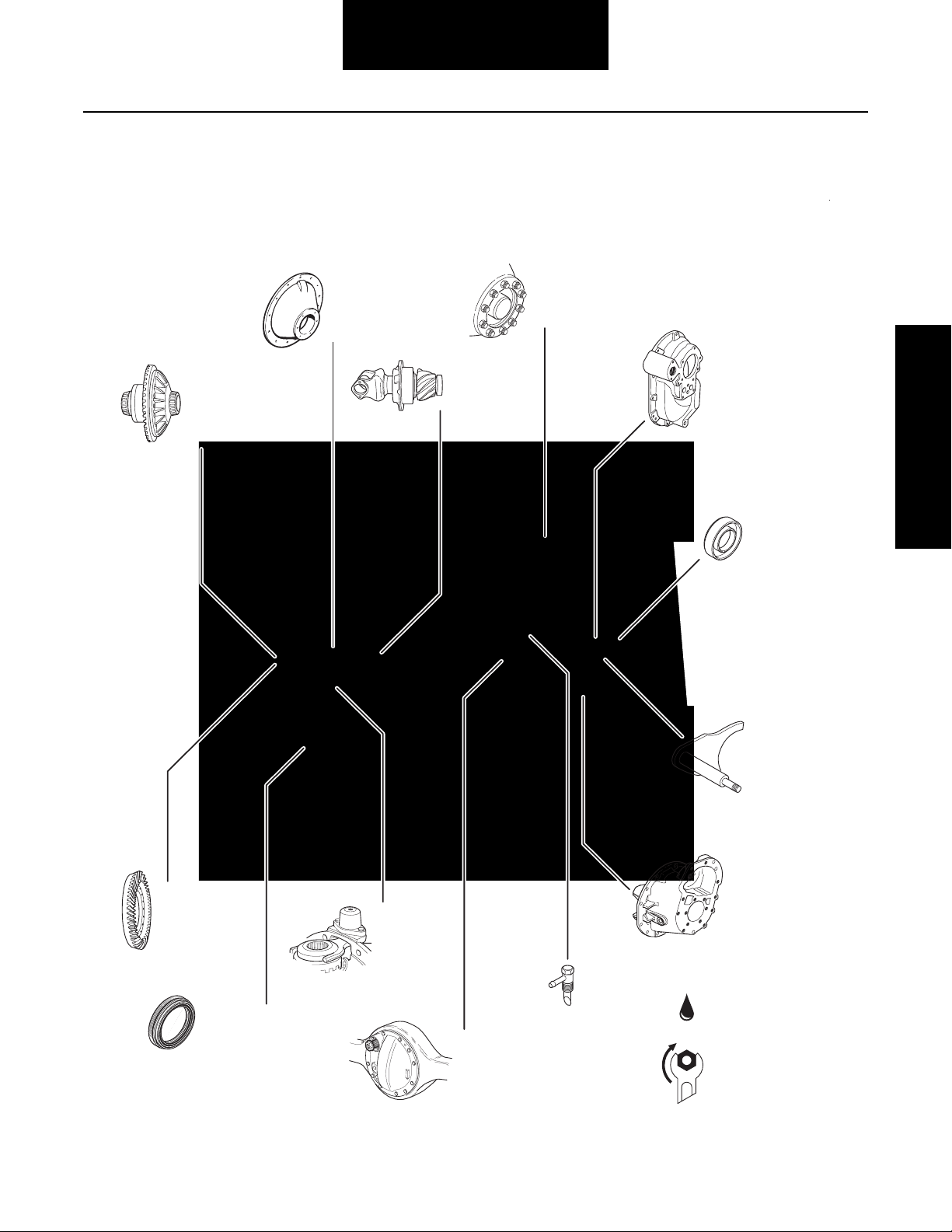
Table of Contents
Table of Contents - Visual
Wheel
Differential
Assembly
Page 68-82
Carrier Assembly
Page 45-56
Drive Pinion
Page 57-67
Wheel End
Page 99-101
Power Divider
Page 24-44
Seals
Page 92-93
Table of Contents
Ring Gear
Page 82-83
Wheel End Seal
Page 95-96
Wheel Adjustment
Systems
Page 97-98
Wheel
Differential Lock
Page 83-90
Housing and
Rear Cover
Assembly
Page 91
Housing Breather
Page 94
Differential
Lockout
Page 17-22
Differential
Carrier Assembly
Page 11-16
Lubrication
Page 102-106
Torque Chart
Page 107-108
ii
Page 4

Table of Contents
Introduction .........................................................1
Failure Analysis ...................................................7
Inspection ...........................................................9
Differential Carrier Assembly - Parts .................11
Differential Lockout ...........................................17
Power Divider
Power Divider - Parts Exploded View........................23
Remove Power Divider............................................. 24
Remove Power Divider from Differential Carrier
(with carrier removed from axle housing)................ 25
Disassemble, Assemble and Overhaul
the Power Divider.....................................................27
Install Power Divider on Differential Carrier
(with carrier assembled to axle housing) .................. 38
Install Power Divider on Differential Carrier
(with carrier removed from axle housing) ................. 40
Dissasemble Differential Carrier
(with power divider removed) ...................................54
Drive Pinion
Drive Pinion - Parts Exploded View............................ 57
Disassemble and Overhaul Drive Pinion.................... 58
Install Drive Pinion Assembly.................................... 65
Wheel Differential Assembly
Wheel Differential Assembly
- Parts Exploded View ............................................... 68
Housing and Rear Cover Assembly
- Parts Exploded View ............................................... 91
Seals.................................................................. 92
Housing Breather .............................................. 94
Wheel End Seal - Parts Exploded View .............95
Remove and Overhaul Wheel End Seal .............96
Wheel Adjustment Systems ..............................97
Verify Wheel End-play Procedure ......................99
Lubricate Wheel End ....................................... 100
Lubrication ......................................................102
Lube Change Intervals ....................................103
Change Lube ...................................................104
Standpipes ......................................................105
Torque Chart ...................................................107
Appendix
Wheel Differential Lock ...........................................109
Differential Lock Theory of Operation ....................110
Control Systems ....................................................111
Dual Range Axle Shift Systems ..............................113
Troubleshooting .....................................................120
Proper Vehicle Towing ...........................................122
Axle Shift System Components ..............................124
Inter-Axle Differential Lockout
With Interlock Control Valve (straight-air type) ......126
Theory of Operation ...............................................129
Power Flow and Torque Distribution ......................130
Lubrication .............................................................132
Torque Distribution in Low Range .........................136
iii
Page 5

Introduction
General Information
Dana Corporation, Axle & Brake Division, presents this publication to aid in maintenance and overhaul of Dana tandem
drive axles. Instructions contained cover the models listed.
Their design is common, with differences in load capacity. Capacity variations are achieved by combining basic differential
carrier assemblies with different axle housings, axle shafts and
wheel equipment.
The suffix letter “P” in the model number indicates lube pump
is standard. Pump models are equipped with a gerotor pump,
designed to provide additional lubrication to the inter-axle differential and related parts.
Carrier Design and Identification
(DT440-P, DT460-P, DT480-P and DP440-P through DP650P)
On August 1, 1981, these axles were converted to a new configuration which includes redesign of the axle differential carrier; input shaft bearing, involute side gear and axle shaft spline
configuration. For carrier identification, see illustrations:
Axles built after August 1, 1981 with Carrier Casting No.
110500
Note: Refer to Dana Parts Book AXIP-0108 for parts informa-
tion.
Input Shaft
Input shaft with Carrier Casting 110500 is equipped with a tapered roller bearing. Casting 103530 uses a ball bearing.
Input Shaft Bearing Spacer
Used only with Carrier Casting 110500.
Pinion Bearing Sleeve
Used only with Carrier Casting 103530.
Pinion Helical Gear Spacer
Used only on DT/DP440-P and DT/DP460-P (ratios 3.90-6.17).
Output Shaft Rear Bearing Retaining Washer
Used only on DT440-P - DT485-P and DP440-P - DP650-P.
Lube Pump Drive Shaft
The drive shaft on early pump design is equipped with a woodruff key. On late pump design, the key is eliminated. The drive
shaft end has two machined flats and the drive gear mounting
hole is shaped to accommodate these flats.
General Information
Axles built before August 1, 1981 with Carrier Casting No.
103530
1
Page 6
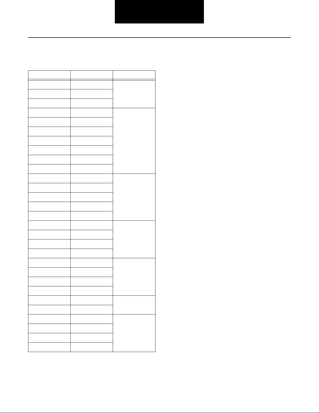
Model Listing
General Information
The following models are included in this publication:
Forward Axle Rear Axle Load Capacity
DP440-P 44,000 lbs.
DS440-P RS440
DT440-P
DP460-P 46,000 lbs.
DS460-P RS460
DT460-P
DD461-P RD461
DP461-P
DS461-P RS461
DT461-P
DP480-P 48,000 lbs.
DS480-P RS480
DT480-P
DP485-P
The suffix letter "P" in the model number indicates the axle is
equipped with a lube pump which provides positive lubrication
in the inter-axle differential and other power divider parts.
Model variations and parts identification information is included throughout this manual. For more detailed parts information, refer to your Dana parts books.
DT485-P
DD521-P RD521 52,000 lbs.
DP521-P
DS521-P RS521
DT521-P
DP580-P 58,000 lbs.
DD581-P RD581
DS581-P RS581
DP581-P
DP601-P 60,000 lbs
DT601-P
DP650-P 65,000 lbs
DP651-P
DT461-P
DP652-P
2
Page 7
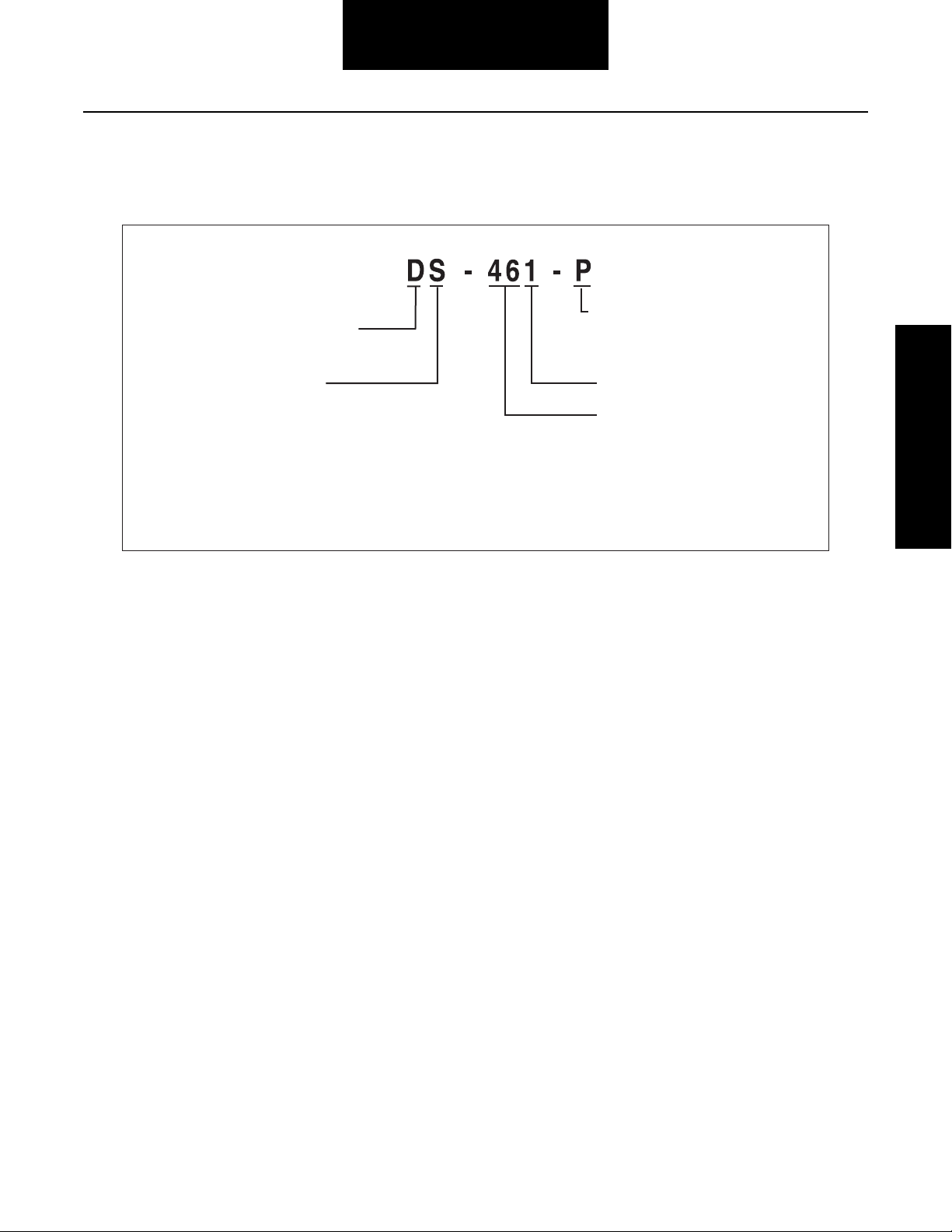
Model Information
General Information
Gearing
D - Forward Tandem Axle
R - Rear Tandem Axle
S - Single Reduction
D - Single Reduction with Wheel
Differential Lock
T - Dual Range
P - Planetary Double Reduction
Example:
DS = Forward Tandem Axle/Single Reduction
RS = Rear Tandem Axle/Single Reduction
Lube Pump
P = Standard
(P) = Optional
Design Level
Capacity (x 1000 lbs.)
Example: 46 = 46,000 lbs.
General Information
3
Page 8
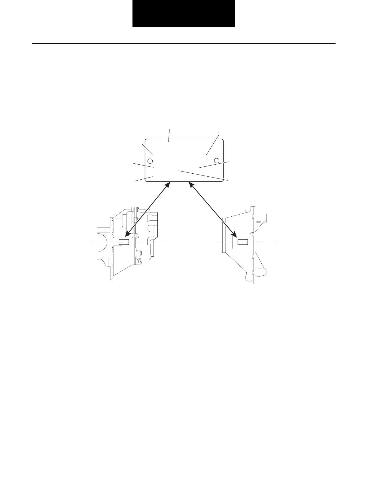
General Information
Model Identification
Drive Axle
Note: Tags that do not include all the information shown here
are older models (before May 1987).
4
3
CUST. PART NO.
Spicer
SPEC. SERIAL NO.
2
5
®
6
MODEL PART NO. RATIO
1
®
CUST. PART NO.
Spicer
SPEC. SERIAL NO.
MODEL PART NO. RATIO
MADE IN:
MADE IN:
Data plate is located on
the axle centerline
7
®
CUST. PART NO.
Spicer
SPEC. SERIAL NO.
MODEL PART NO. RATIO
MADE IN:
Forward Axle (Side View) Rear Axle (Top View)
1 - Country or origin
2 - Axle model identification
3 - Specification number assigned to the axle built by Spicer. Identifies all component parts of the axle including special OEM
requirements such as yokes or flanges.
4 - OEM part number assigned to the axle build
5 - Carrier assembly serial number assigned by the manufacturing plant
6 - Axle gear ratio
7 - Carrier assembly production or service part number
4
Page 9
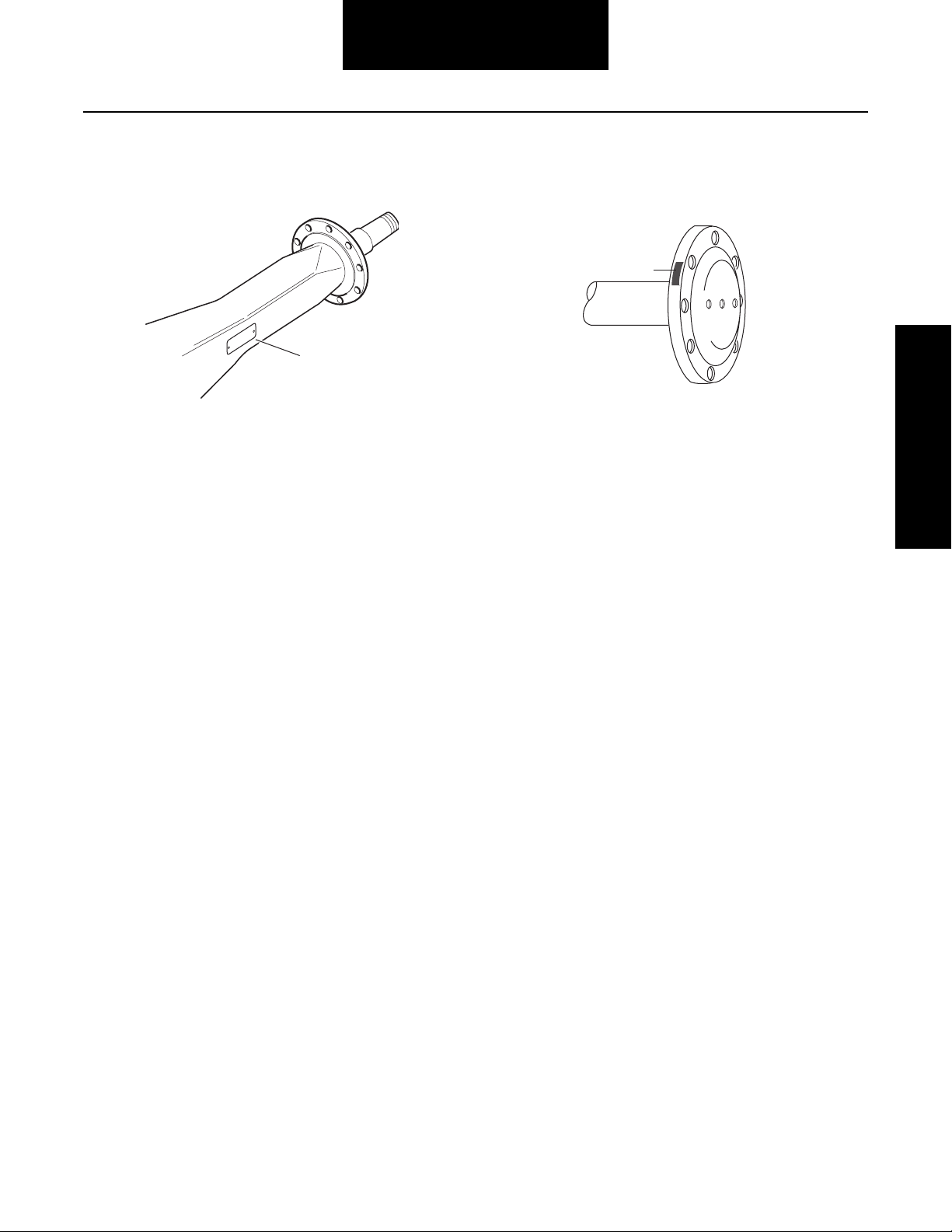
General Information
Part Identification
Axle Housing Axle Shaft
®
Spicer
PT. NO.
O.
HSG. CAP. LBS.
E IN
HSG. I.D. N
HOUSING MAD
1 - ID Tag 2 - Axle shaft part number
1
2
General Information
5
Page 10
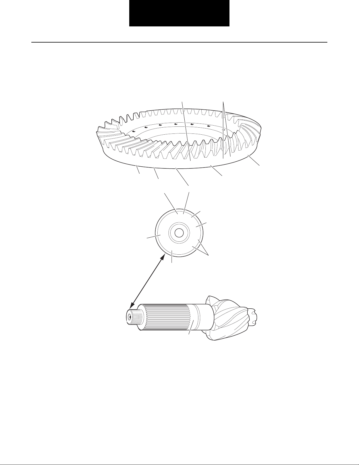
General Information
Ring Gear and Pinion
Note: Ring gear and drive pinion are matched parts and must
be replaced in sets.
127381
1
SPICER
7
7
5
SPICER
127
1
41-8
8-41
127428
8
NL2
3
L7038
G
17
OF
4
6
2
8
127
G
0H
6
17
3
1 - Part number
2 - Number of ring gear teeth
3 - Manufacturing numbers
4 - Matching gear set number
5 - Number of pinion teeth
6 - Date code
7 - Indicates genuine Spicer parts
8 - Heat code
6
L
7
6-39
JD77
85405
86
0
3
8
4
Page 11

Failure Analysis
Failure Analysis
Failure analysis is the process of determining the original
cause of a component failure in order to keep it from happening again. Too often, when a failed component is replaced without determining its cause, there will be a recurring failure. If a
carrier housing is opened, revealing a ring gear with a broken
tooth, it is not enough to settle on the broken tooth as the
cause of the carrier failure. Other parts of the carrier must be
examined. For a thorough understanding of the failure and
possible insight into related problems, the technician needs to
observe the overall condition of the vehicle.
No one benefits when a failed component goes on the junk pile
with the cause unknown. Nothing is more disturbing to a customer than a repeat failure. Systematically analyzing a failure
to prevent a repeat occurrence assures quality service by
avoiding unnecessary downtime and further expense to the
customer.
The true cause of a failure can be better determined by knowing what to look for, determining how a piece of the equipment
was running and learning about previous problems. In the case
of a rebuilt rear axle, mismatched gears may have been installed. The more successful shops prevent repeat equipment
failures by developing good failure analysis practices. Knowing
how to diagnose the cause of a premature failure is one of the
prerequisites of a good heavy-equipment technician.
How to Diagnose a Failure
The following five steps are an effective approach to good failure diagnostics.
1. Document the problem.
2. Make a preliminary investigation.
3. Prepare the parts for inspection.
4. Find the cause of the failure.
5. Correct the cause of the problem.
Document the Problem
Here are some guidelines for starting to learn about a failure,
including questions to ask:
• Talk to the operator of the truck.
• Look at the service records.
• Find out when the truck was last serviced.
• Ask: In what type of service is the truck being used?
• Ask: Has this particular failure occurred before?
• Ask: How was the truck working prior to the failure?
Failure Analysis
You need to be a good listener. Sometimes, insignificant or unrelated symptoms can point to the cause of the failure.
• Ask: Was the vehicle operating at normal temperatures?
• Ask: Were the gauges showing normal ranges of operation?
• Ask: Was there any unusual noise or vibration?
After listening, review the previous repair and maintenance
records. If there is more than one driver, talk to all of them and
compare their observations for consistency with the service
and maintenance records. Verify the chassis Vehicle Identification Number (VIN) number from the vehicle identification
plate, as well as the mileage and hours on the vehicle.
7
Page 12

Failure Analysis
Make a Preliminary Investigation
These steps consist of external inspections and observations
that will be valuable when combined with the results of the
parts examination.
• Look for leaks, cracks or other damage that can point
to the cause of the failure.
• Make note of obvious leaks around plugs and seals.
A missing fill or drain plug would be an obvious cause
for concern.
• Look for cracks in the carrier housing (harder to see,
but sometimes visible).
• Does the general mechanical condition of the vehicle
indicate proper maintenance or are there signs of neglect?
• Are the tires in good condition and do the sizes
match?
• If equipped with a torque-limiting device, is it working
properly?
During the preliminary investigation, write down anything out
of the ordinary for later reference. Items that appear insignificant now may take on more importance when the subassemblies are torn down.
Find the Cause of the Failure
Here begins the real challenge to determine the exact cause of
the failure. Keep in mind that there is no benefit to replacing a
failed part without determining the cause of the failure. For example, after examining a failed part and finding that the failure
is caused by a lack of lubrication, you must determine if there
was an external leak. Obviously, if there is an external leak, just
replacing the failed gear is not going to correct the situation.
Another important consideration here is to determine the specific type of failure which can be a valuable indicator for the
cause of failure. The following pages show different types of
failures and possible causes. Use this as a guide in determining types of failures and in correcting problems.
Correct the Cause of the Problem
Once the cause of the problem has been determined, refer to
the appropriate service manual to perform the repairs.
Prepare the Parts for Inspection
After the preliminary investigation, locate the failure and prepare the part for examination. In carrier failure analysis, it may
be necessary to disassemble the unit.
• When disassembling subassemblies and parts, do
not clean the parts immediately since cleaning may
destroy some of the evidence.
• When tearing down the drive axle, do it in the recommended manner. Minimize any further damage to the
unit.
• Ask more questions when examining the interior of
the carrier. Does the lubricant meet the manufacturer
specifications regarding quality, quantity and viscosity? As soon as you have located the failed part, take
time to analyze the data.
8
Page 13
Inspection
Inspection
Clean
1. Wash steel parts with ground or polished surfaces in
solvent. There are many suitable commercial solvents available. Kerosene and diesel fuel are acceptable.
WARNING
Gasoline is not an acceptable solvent because of its extreme
combustibility. It is unsafe in the workshop environment.
2. Wash castings or other rough parts in solvent or
clean in hot solution tanks using mild alkali solutions.
Note: If a hot solution tank is used, make sure parts are heated
thoroughly before rinsing.
3. Rinse thoroughly to remove all traces of the cleaning
solution.
4. Dry parts immediately with clean rags.
5. Oil parts.
• If parts are to be reused immediately: Lightly oil.
• If parts are to be stored: Coat with oil, wrap in
corrosion resistant paper and store in a clean,
dry place.
Note: Replace conventional gaskets with silicone rubber gas-
ket compound (included in many repair kits). The compound provides a more effective seal against lube
seepage and is easier to remove from mating surfaces
when replacing parts.
1
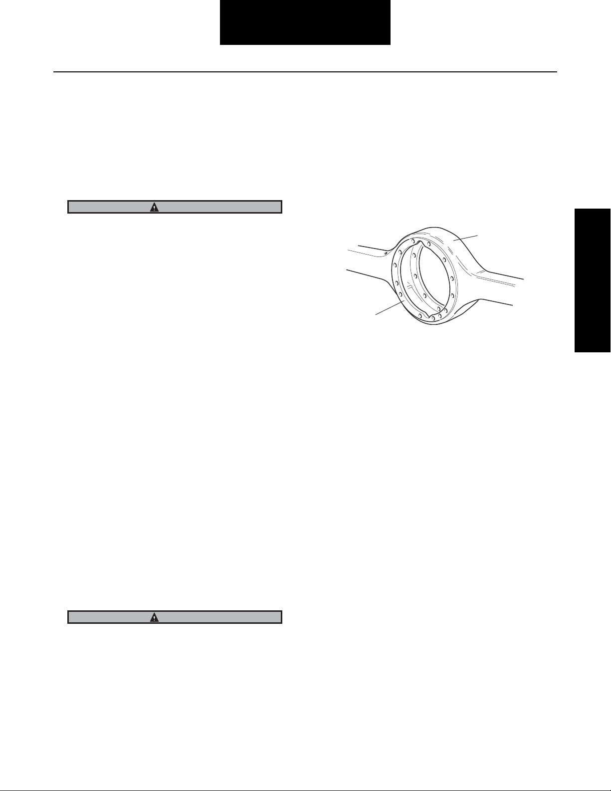
Inspection
2
1 - Axle housing
2 - Machined surface
Inspect Components
Inspect all steel parts for:
• Notches, visible steps or grooves created by wear
Inspect Axle Housing
Axle housing inspection and repairs are limited to the following
checks or repairs:
• Visually inspect axle housing for cracks, nicks and
burrs on machined surfaces.
• Check carrier bolt holes and studs for foreign material.
• Replace damaged fasteners. Look for loose studs or
cross threaded holes.
CAUTION
Any damage which affects the alignment or structural integrity of the housing requires housing replacement. Do not repair by bending or straightening . This process can affect
the material's properties and cause it to fail completely under load.
• Check all seals and gaskets.
• Pitting or cracking along gear contact lines
• Scuffing, deformation or discolorations. These are
signs of excessive heat in the axle and are usually related to low lubrication levels or improper lubrication
practices.
In addition, inspect the following for damage:
• Differential gearing
• Bearings for loose fit on drive pinion, pilot bearing,
and differential bearings
• All fasteners for rounded heads, bends, cracks or
damaged threads.
• Inspect machined surfaces of cast or malleable parts.
They must be free of nicks, burrs, cracks, scoring,
and wear.
• Look for elongation of drilled holes, wear on surfaces
machined for bearing fits and nicks or burrs in mating
surfaces.
9
Page 14
Inspection
Inspect Primary Gearing
Before reusing a primary gear set, inspect teeth for signs of excessive wear. Check tooth contact pattern for evidence of incorrect adjustment.
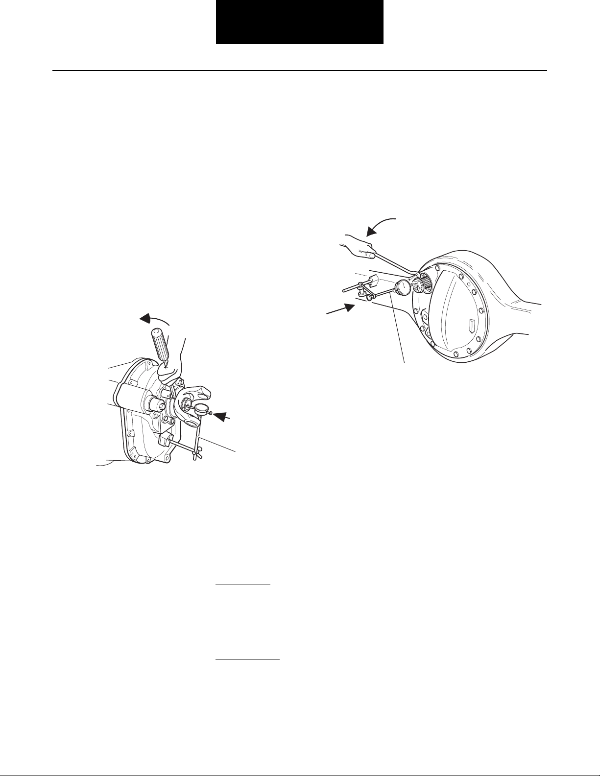
Check Input Shaft End-play (Forward Axle)
Note: Before disassembling the power divider, measure and
record input shaft end-play.
See illustration for steps 1-3.
1. Position dial indicator at yoke end of input shaft.
2. Push in on input shaft and zero the dial indicator.
3. Using a pry bar, move input shaft axially and measure/record end-play.
3
Check Output Shaft End-play
(Forward Axle)
See illustration for steps 1-3.
1. Position dial indicator at yoke end of output shaft.
2. Push in on output shaft and zero the dial indicator.
3. Using a pry bar, move input shaft axially and measure/record end-play.
3
2
1
2
1
Adjustment
Correct end-play for a new assembly is .003" to .007". The
maximum end-play for a used assembly is no more than .014".
If end-play is incorrect, determine shim pack changes as follows:
Add shims to increase end-play
Desired end-play (New Parts) 0.003" to 0.007"
Measured end-play (Step 3) 0.001”-0.001”
Add shims to provide desired end-play 0.002" to 0.006"
Remove shim to decrease end-play
Measured end-play (Step 3) 0.015" – 0.015"
Desired end-play (New Parts) 0.003” to 0.007”
Remove shims to provide desired endplay
0.012” to 0.008”
Adjustment
Correct end-play for a new assembly is .001" to .005". The
maximum end-play for a used assembly is no more than .005".
If end-play is incorrect, contact Dana.
10
Page 15
Differential Carrier Assembly
y
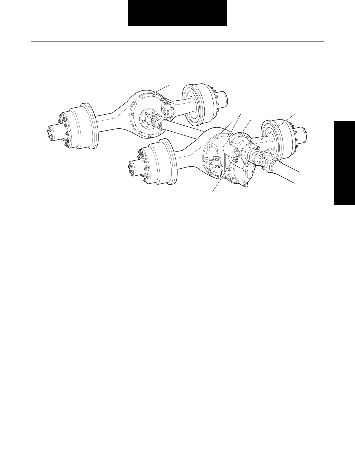
Differential Carrier Assembly - Parts
5
1 - Carrier fasteners
2 - Carrier assembly
3 - Forward axle assembly
4 - Inter-axle differential lockout
5 - Rear axle assembly
1
2
3
Differential Carrier
Assembl
4
11
Page 16
Differential Carrier Assembly
Forward Axle Differential Carrier Removal and Installation
Removal of Forward Differential Carrier
Note: The removal of the forward carrier requires disconnect-
ing of the inter-axle driveline and removal of the output
shaft yoke assembly.
1. Block the vehicle.
2. Drain axle lubricant.
3. Disconnect all air lines to the axle.
4. Disconnect inter-axle and main drivelines.
5. Remove axle stud nuts and axle shafts (If used, remove lock washers and taper dowels).
WARNING
The differential lock 461/521/581 models use axle shafts
with different spline length (4" or 11"). Axle shafts may also
be location specific with various wheel equipment. Do not
misplace axle shafts from their intended location.
TIP: To loosen dowels, hold a brass drift in the center of the
shaft head and strike drift with a sharp blow using a hammer.
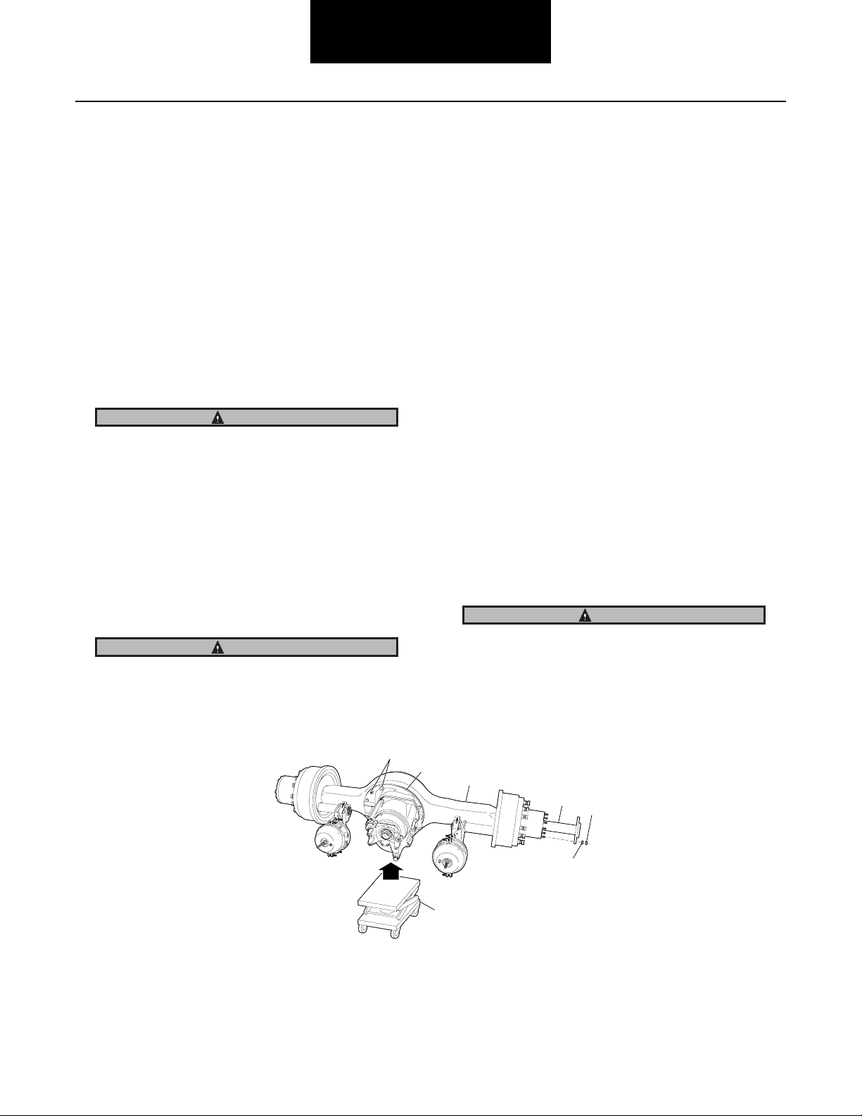
Do not lie under carrier after fasteners are removed. Use
transmission jack to support differential carrier assembly
prior to loosening fasteners.
6. Remove carrier capscrews, nuts and lock washers.
7. Forward Models Only: Remove output shaft shoulder nut and yoke.
8. Remove differential carrier assembly.
Removal of Forward Axle Housing Cover
Tip: The bearing parts can be serviced separately
without removing the housing cover form the axle
housing
1. Block the vehicle.
2. Drain axle lubricant.
3. Disconnect inter-axle driveline.
4. Remove output shaft shoulder nut and yoke.
5. Remove capscrews, nuts, and lock washers fastening cover to axle housing.
6. Remove oil seal and discard.
7. Remove bearing retaining washer, if used.
8. If replacement is necessary, remove snap ring, bearing and bearing sleeve.
WARNING
CAUTION
Do not strike the shaft head with a steel hammer. Do not use
chisels or wedges to loosen shaft or dowels.
1
1 - Carrier fasteners
2 - Carrier assembly
3 - Forward axle assembly
4 - Axle shaft
Snap ring is spring steel and may pop off. Wear safety glasses when removing.
2
3
4
5
6
7
5 - Nut
6 - Lock washer
7 - Lift and support
12
Page 17
Inspection
Installation of Forward Differential Carrier
IMPORTANT
Before installing carrier assembly, inspect and thoroughly
clean interior of axle housing using an appropriate solvent
and clean rag.
IMPORTANT
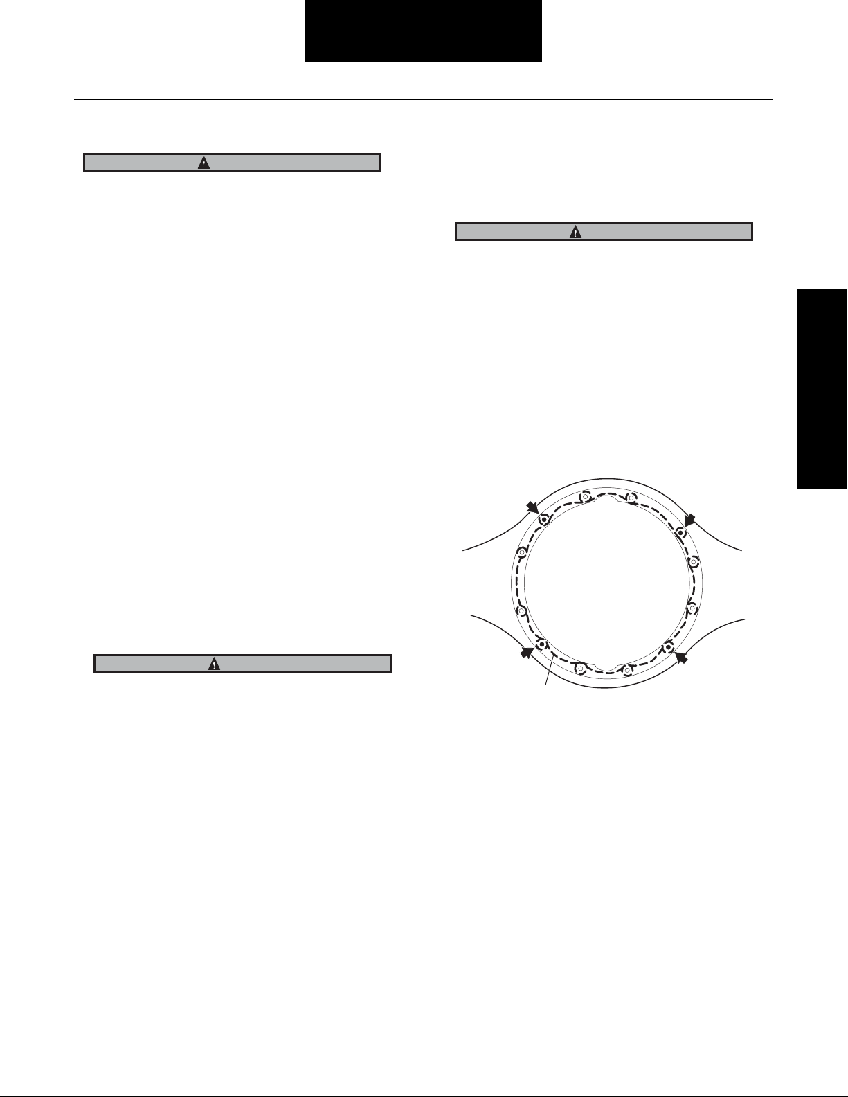
1. Use silicone rubber gasket compound on axle housing mating surface as shown in the illustration. Completely remove all old gasket material prior to
applying new material. Compound will set in 20 minutes. Install carrier before compound sets or reapply.
TIP: To assist in installing complete differential carrier, use two pieces of threaded rod (5/8"- 11 UNS)
threaded into carrier capscrew holes. Rod should be
approximately 6" long. Use these to pilot the carrier
into the housing.
2. Install differential carrier assembly to axle housing
using lockwashers, capscrews and nuts. Torque to
proper specification (see Torque Chart on page 107).
3. With the forward axle now assembled to the housing,
proceed with Installation of Forward Axle Housing
Cover and Output Shaft Bearing Parts, on next page.
4. Install output yoke and self-locking nut. Tighten to
specified torque (see Torque Chart on page 107).
Reference Yoke Installation Section page 92.
5. Install axle shafts and axle stud nuts (If used, also install lock washers and taper dowels).
WARNING
When axle has been disassembled
or housing, axle shafts or wheel equipment re
placed, check axle assembly for proper differen-
tial action before operating vehicle. Wheels must
rotate freely and independently.
Road test vehicle to bring axle lubricant up to temperature. Recheck joints, drain and fill plugs for leakage. Re-tighten as necessary.
Differential Carrier Side of Axle Housing
2
Inspection
The differential lock 461/521/581 models use axle shafts
with different spline length (4" or 11"). Axle shafts may also
be location specific with various wheel equipment. Do not
misplace axle shafts from their intended location.
6. Connect main and inter-axle driveline. Ensure drivelines are properly phased. Lubricate U-joints.
7. Add axle lubricant. See Lube Fill Capacities on page
104 for correct amount.
Note: Oil fill plug removed from D461/462/463 Differential
Carriers. The oil fill plug hole located in the differential
carrier was removed. Lube capacity is not affected, customers to fill axle with lube through rear cover fill hole or
through the breather hole in housing. February 1, 2000.
8. Connect air lines to differential.
1
Axle Housing Silicone Gasket Compound Pattern
1 - Apply silicone gasket in this pattern
2 - Typical stud locations
13
Page 18
Differential Carrier Assembly
Installation of Forward Axle Housing Cover and Output Shaft Bearing Parts
Note: Forward axle should be assembled to the axle housing
before proceeding with the following procedure.
1. If removed, install housing cover and fasten with
nuts, capscrews and lock washers. Tighten to proper
torque specifications (see Torque Chart on page
107).
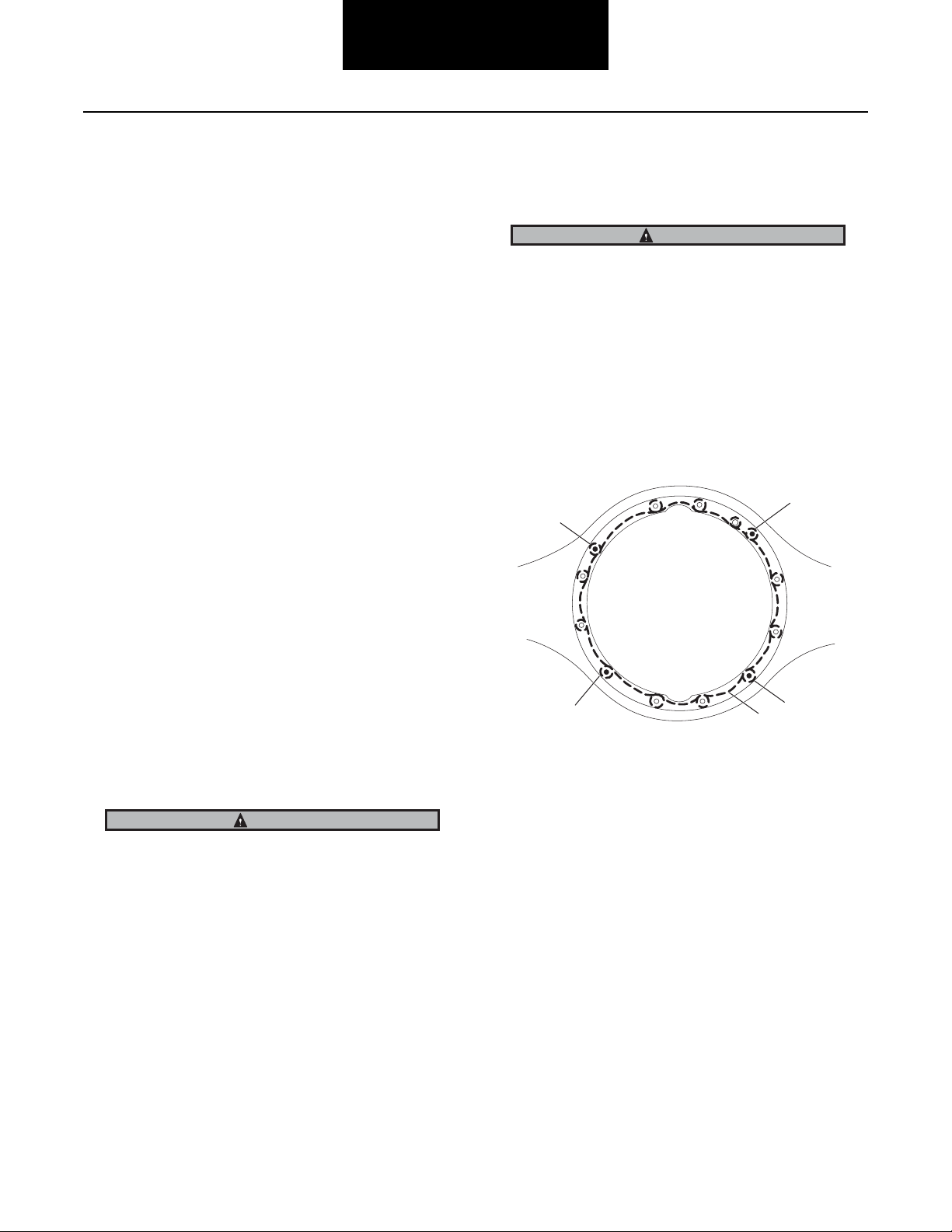
Note: Use silicone rubber gasket compound on axle housing
mating surface as shown in illustration. Completely remove all old gasket material prior to applying new material. Compound will set in 20 minutes. Install axle
housing cover and output shaft assembly before compound sets or reapply.
2. Install output shaft rear bearing. Tap the outer race
(with a sleeve or brass drift) until it is seated firmly in
the machined pocket of the cover. Secure with snap
ring.
IMPORTANT
When axle has been disassembled or housing, axle shafts or
wheel equipment replaced, check axle assembly for proper
differential action before operating vehicle. Wheels must rotate freely and independently.
Road test vehicle to bring axle lubricant up to temperature. Recheck joints, drain and fill plugs for leakage. Re-tighten as necessary.
Cover Side of Axle Housing
2
2
3. Lubricate and install the rear bearing sleeve on the
output shaft. Make certain it fits snugly against the
shoulder at the forward edge of the shaft splines.
4. Install the output shaft seal in the axle housing cover.
Note: Some axles require the use of a rear bearing retaining
washer. Install the washer over the splines of the output
shaft flush against the output shaft bearing.
5. Install output yoke and self-locking nut. Tighten to
specified torque (see Torque Chart on page 107).
Reference Yoke Installation Section page 92.
6. Install axle shafts and axle stud nuts (If used, also install lock washers and taper dowels).
WARNING
The differential lock 461/521/581 models use axle shafts
with different spline length (4" or 11"). Axle shafts may also
be location specific with various wheel equipment. Do not
misplace axle shafts from their intended location.
7. Connect main and inter-axle driveline. Ensure drivelines are properly phased. Lubricate U-joints.
8. Add axle lubricant. See Lube Fill Capactities on page
104 for correct amount.
2
1 - Apply silicone gasket in this pattern
2 - Stud locations (varies by model)
2
1
Note: Oil fill plug removed from D461/462/463 Differential
Carriers. The oil fill plug hole located in the differential
carrier was removed. Lube capacity is not affected, customers to fill axle with lube through rear cover fill hole or
through the breather hole in housing. February 1, 2000.
9. Connect air lines to differential.
14
Page 19

Differential Carrier Assembly
y
Rear Axle Differential Carrier Removal and Installation
Removal of Rear Differential Carrier
Perform the following steps:
1. Block the vehicle.
2. Drain axle lubricant.
3. Disconnect air line if working on a differential lock axle. (See Differential Lockout Section).
4. Disconnect inter-axle driveline.
5. Remove axle stud nuts and axle shafts (If used, remove lock washers and taper dowels).
WARNING
The differential lock 461/521/581 models use axle shafts
with different spline length (4" or 11"). Axle shafts may also
be location specific with various wheel equipment. Do not
misplace axle shafts from their intended location.
1
TIP: To loosen dowels, hold a brass drift in the center of the
shaft head and strike drift with a sharp blow using a hammer.
Do not lie under carrier after fasteners are removed. Use
transmission jack to support differential carrier assembly
prior to loosening fasteners.
CAUTION
Do not strike the shaft head with a steel hammer. Do not use
chisels or wedges to loosen shaft or dowels.
6. Remove capscrews, nuts and lock washers.
7. Remove differential carrier assembly.
2
3
Differential Carrier
Assembl
1 - Carrier fasteners
2 - Carrier assembly
3 - Rear axle assembly
4
5
6
4 - Axle shaft
5 - Nut
6 - Lock washer
15
Page 20
Differential Carrier Assembly
Rear Differential Carrier “Installation”
IMPORTANT
Before installing carrier assembly, inspect and thoroughly
clean interior of axle housing using an appropriate solvent
and clean rag.
Note:
Note:
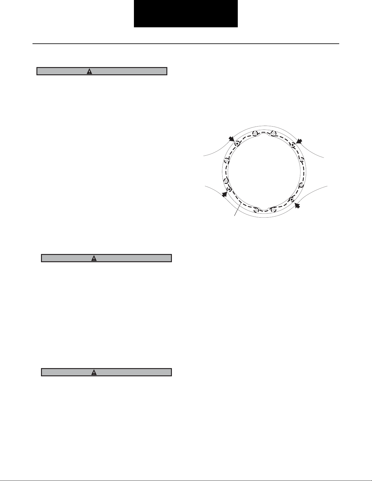
Note: Apply silicone rubber gasket compound on axle housing
mating surface as shown in illustration. Completely remove all old gasket material prior to applying new material. Compound will set in 20 minutes. Install carrier
before compound sets or reapply.
1. Install differential carrier assembly.
TIP: To assist in installing complete differential carrier use two pieces of threaded rod (5/8"- 11 UNS)
threaded into carrier capscrew holes. Rod should be
approximately 6" long. Use these to pilot the carrier
into the housing.
2. Install carrier to axle housing lock washers, capscrews and nuts. Torque to proper specification. See
“Torque Chart” on page 107.
3. Install axle shafts and axle stud nuts (If used, also install lock washers and taper dowels).
WARNING
Road test vehicle to bring axle lubricant up to temperature. Recheck joints, drain and fill plugs for leakage. Re-tighten as necessary.
2
1
1 - Apply silicone gasket in this pattern
2 - Typical stud locations
The differential lock 461/521/581 models use axle shafts
with different spline length (4" or 11"). Axle shafts may also
be location specific with various wheel equipment. Do not
misplace axle shafts from their intended location.
4. Connect inter-axle driveline, making sure driveline is
in phase. Lubricate U-joints.
5. Add axle lubricant. Fill to bottom of filler hole. See
“Change Lube” on page 104. Reference Lube Fill Capacities for correct amount.
6. Connect air line to differential if working on a differential lock model axle.
IMPORTANT
When axle has been disassembled or housing axle shafts or
wheel equipment replaced, check axle assembly Afor proper
differential action before operating vehicle. Wheels must rotate freely and independently.
16
Page 21
Differential Lockout
Differential Lockout
Inter-Axle Lockout Types
All are air-operated to engage the lockout and spring-released
to disengage the lockout with the exception of the “ReverseAir” lockout. The “Reverse-Air” lockout is spring-released to
engage the lockout and air-operated to disengage the lockout.
1
Cast Iron Cover Lockout - February 1996 to
Present (Single Reduction Models)
• External type lockout
• Cast iron piston cover
2
3 4
5
6 7
Differential Lockout
8
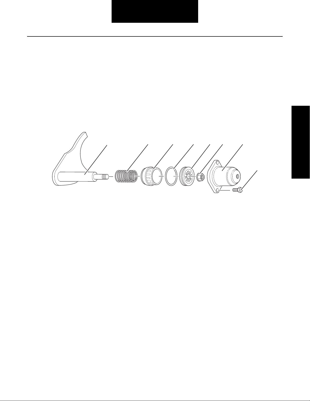
1 - Shift fork assembly
2 - Compression spring
3 - Piston driver
4 - O-ring
5 - Piston
6 - Lock nut
7 - Cast iron piston housing
8 - Capscrew
17
Page 22
Differential Lockout
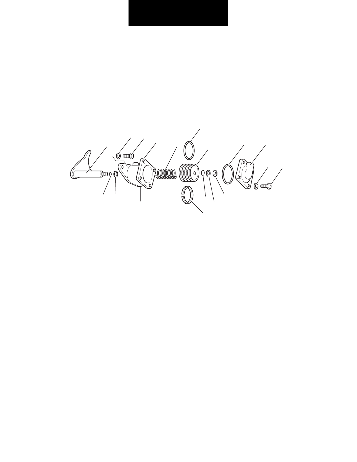
Original Design Lockout - 1948 to Present
(*Optional design for use with all dual
range tandem axles)
• Die cast body
• Square Top
4
5
1
2
3
Original
design
6
• Interchangeable with cast iron lockout*
“In 1985, a “Protective Shift System” was released into production axles. Dana bulletin 85-03 explains this popular OEM
option. This option can only work with the “original” design
lockouts.
7
13
1514
8
16
17
10
12
11
9
1 - Shift fork assembly
2 - Push rod o-ring
3 - Body o-ring
4 - Lock washer
5 - Cap screw
6 - Original design lockout body
7 - Piston o-ring
8 - Piston
9 - Felt oilers
10 - O-ring
11 - Flat washer
12 - Lock nut
13 - Compression spring
14 - Cover o-ring
15 - Cover
16 - Lock washer
17 - Capscrew
18
Page 23
Differential Lockout
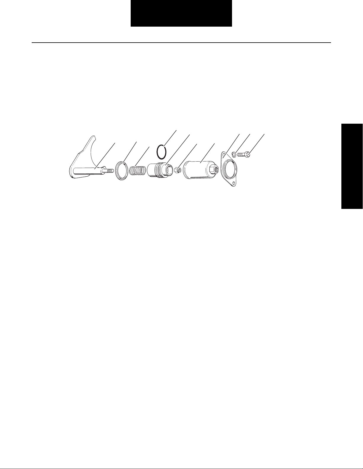
Cylindrical Design Lockout - October 1989
to February 1996
• External type lockout
1
2
3
• Stamped steel piston cover
• Interchangeable with the cast style cover only as a
complete assembly
4
5
6
7
8 9
10
Differential Lockout
1 - Shift fork assembly
2 - Shoulder washer
3 - Compression spring
4 - O-ring
5 - Piston
6 - Lock nut
7 - Cylindrical design piston housing
8 - Mounting bracket
9 - Lock washer
10 - Capscrew
19
Page 24
Differential Lockout Overhaul
Differential Lockout
Instructions for the three different designs are on the following
pages:
Cast Iron Cover Lockout - Overhaul on page 20
Original Design Lockout - Overhaul on page 21
Cylindrical Design Lockout - Overhaul on page 22
Cast Iron Cover Lockout - Overhaul
Disassemble and Remove Lockout
Note: With axle installed in vehicle, place differential lock se-
lector valve in the disengaged (or unlocked) position.
Disconnect the air line at the lockout piston cover.
1. Remove capscrews and lock washers fastening piston housing to power divider cover. Remove the cast
iron piston housing.
2. Remove lock nut, piston with o-ring, piston driver
and compression spring from push rod.
Assemble and Install Lockout - Cast Iron
Cover Design
1. With shift fork and sliding clutch installed, install
compression spring on push rod.
2. Place piston driver on push rod against compression
spring. The large diameter end of piston driver must
face power divider cover.
3. Lubricate o-ring with silicone-based lubricant and install o-ring on piston.
4. Place piston assembly on push rod against piston
driver.
5. Install lock nut on push rod and tighten to 13-17 lbs.
ft. (18-23 N•m).
6. Apply silicone gasket compound to mounting surface
on power divider cover.
Note: The shift fork and push rod cannot be removed with
power divider cover installed (see Remove Power Divider on
page 24).
Lockout Interchangeability
The cast iron design lockout assembly is interchangeable with
previously designed lockouts, only as a complete assembly.
The original shift fork and push rod can be used for all three
design type lockouts and need not be replaced.
Retrofit kits are available to convert the non-current design
lockouts to the current cast iron cover design lockout. For additional information, refer to Dana Parts Books AXIP-0085.
Retrofit as follows:
1. Disassemble and remove the old design lockout.
2. Assemble and install the cast iron cover lock-out.
CAUTION
Mounting screws are not interchangeable between the various design style lockouts. They are a different length and
size.
1
1 - Lockout silicone gasket pattern
7. Install piston housing cover.
8. Install capscrews and tighten to 48-56 lbs. ft.
(65-76 N•m).
9. If axle is installed in vehicle, apply sealant to air line
fitting and connect air line.
20
Page 25
Original Design Lockout Overhaul
Differential Lockout
Note: Find instructions for:
Cast Iron Cover Lockout - Overhaul on page 20
Cylindrical Design Lockout - Overhaul on page 22
Disassemble and Remove Lockout
Note: With axle installed in vehicle, place differential lock se-
lector valve in the disengaged (or unlocked) position.
Disconnect the air line at the lockout piston cover.
1. Remove capscrews and lock washers fastening cover to the body. Remove cover and o-ring.
2. Remove nut, flat washer and o-ring from push rod.
3. Remove body capscrews and lock washers, then remove body and piston as an assembly. Remove oring and felt oilers from the piston.
Note: The shift fork and push rod cannot be removed with
power divider cover installed (see Remove Power Divider on
page 24).
Retrofit Original Design to Cast Iron Cover
Design Lockout
Assemble and Install Original Design Lockout
With shift fork and sliding clutch installed in power divider cover, assemble and install lockout as follows:
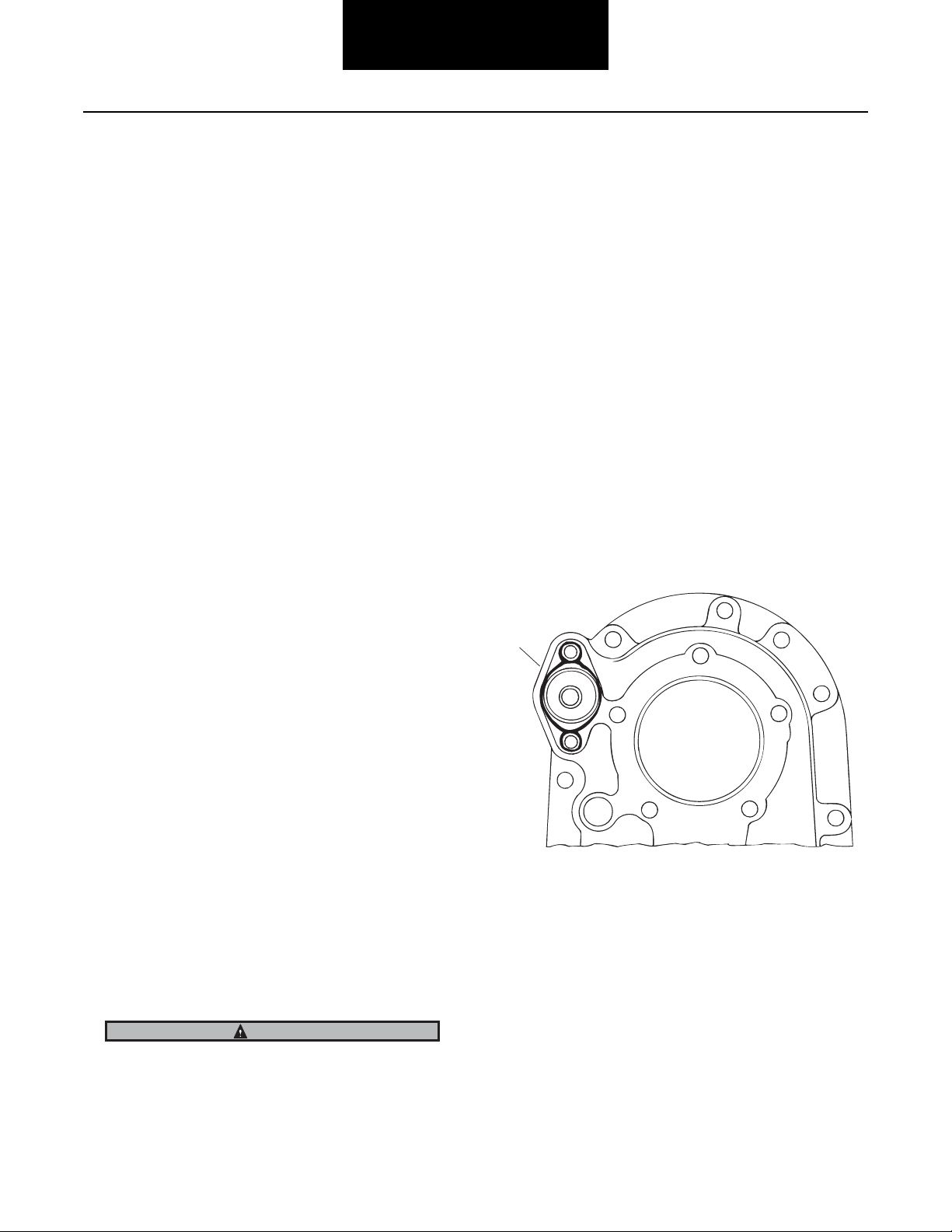
1. Apply silicone gasket compound to mounting surface
on power divider cover.
Differential Lockout
1
1 - Lockout silicone gasket pattern
The cast iron cover design lockout assembly is interchangeable with the original design lockout, only as a complete assembly. The original shift fork and push rod can be used for
either model lockout and need not be replaced.
Retrofit kits are available to convert the non-current design
lockouts to the current cast iron cover design lockout. For additional information, refer to Dana Parts Books AXIP-0085.
Retrofit as follows:
1. Disassemble and remove the original design lockout.
2. Assemble and install the cast iron cover lockout.
CAUTION
Mounting screws are not interchangeable between the various design style lockouts. They are a different length and
size.
2. Install lockout body. Secure with capscrews and lock
washers. Torque capscrews to 48-56 lbs. ft.
(65-76 N•m).
Note: Before installation, soak piston felt oilers in SAE 30 en-
gine oil and lubricate o-rings with a high-viscosity silicone oil or barium grease o-ring lubricant.
3. Install felt oilers and large o-ring on piston.
4. Install compression spring over shift fork push rod.
Install piston over end of shift fork into lockout body.
Secure with lock washers and lock nut. Torque locknut (see Torque Chart on page 107).
5. Install o-ring in lockout body cover. Install cover and
secure with capscrews and lock washers. Torque
capscrews to 96-108 lbs. in. (10-13 N•m).
21
Page 26
Differential Lockout
Cylindrical Design Lockout - Overhaul
Note: Find instructions for:
Cast Iron Cover Lockout - Overhaul on page 20
Original Design Lockout - Overhaul on page 21
Disassemble and Remove Lockout
Note: With axle installed in vehicle, place differential lock se-
lector valve in the disengaged (or unlocked) position.
Disconnect the air line at the lockout piston cover.
1. Remove capscrews and lock washers fastening
mounting bracket to power divider cover. Remove
bracket and piston housing.
2. Remove lock nut, piston with o-ring, compression
spring and shoulder washer from push rod.
Note: The shift fork and push rod cannot be removed with
power divider cover installed (see Remove Power Divider
on page 24).
Retrofit Cylindrical Design to Cast Iron
Cover Design Lockout
Assemble and Install Lockout-Cylindrical
Design
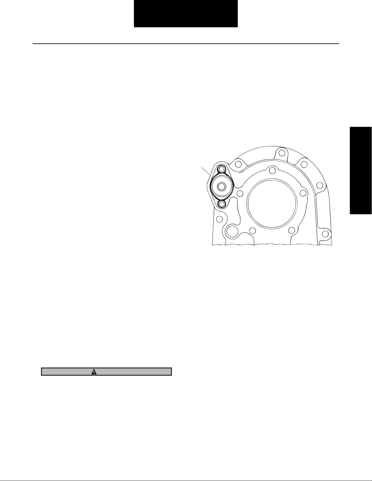
1. With shift fork and sliding clutch installed, place the
shoulder washer (white plastic) over push rod. The
large diameter side of the washer must face the power divider cover.
2. Install compression spring on push rod.
3. Lubricate o-ring with silicone-based lubricant and install o-ring on piston.
4. Place piston assembly on push rod. The large diameter end of piston must face power divider cover.
5. Install lock nut on push rod and tighten to 13-17 lbs.
ft. (18-23 N•m).
6. Install piston housing, making sure the housing is
correctly seated and piloted in the shoulder washer.
The cast iron cover design lockout assembly is interchangeable with the cylindrical design lockout, only as a complete assembly. The original shift fork and push rod can be used for
either type lockout and need not be replaced.
Retrofit kits are available to convert the non-current design
lockouts to the current cast iron cover design lockout. For additional information, refer to Dana Parts Books AXIP-0085.
Retrofit as follows:
1. Disassemble and remove the cylindrical design lockout.
2. Assemble and install the cast iron cover lockout.
CAUTION
Mounting screws are not interchangeable between various
design style lockouts. They are a different length and size.
1
1 - Shoulder washer must seat properly
7. Place mounting bracket over housing and position on
power divider cover. Install capscrews and lock
washers and tighten to 48-56 lbs. ft. (65-76 N•m)
Note: If axle is installed in vehicle, apply sealant to air line fit-
ting and connect air line. When tightening air line, hold
piston housing in mounting position using a wrench applied to the hexagon configuration at outer end of housing.
22
Page 27

Power Divider - Parts Exploded View
1
2* 3 4 5
Inspection
678 910
11
12
13
19 21 22 23 24 25 27 28 29 31 32 33 35
18
20
26
39
40
41
30
42 44 45 47 48
34
36 37 38
4643
49
1517 16
14
Inspection
1 - Output shaft
2 - Bushings*
3 - O-rings
4 - Bearing cup
5 - Bearing cone
6 - Side gear
7 - Snap ring
8 - Spring
9 - Button
10 - Inter-axle differential assembly
11 - Capscrew
12 - Case half
13 - Spider
14 - Nut
* Removed in September 1994
15 - Case half
16 - Side pinion
17 - Thrust washer
18 - Snap ring
19 - Helical gear
20 - Bushings
21 - Thrust washer
22 - “D” washer
23 - Lockout sliding clutch
24 - Input shaft
25 - Bearing cone
25 - Shift fork and push rod
27 - Power divider cover
28 - Lock washer
29 - Capscrew
30 - Lockout unit
31 - Bearing cup
32 - Shim
33 - Bearing cover
34 - Capscrew
35 - Oil seal
36 - Yoke
37 - Flat washer
38 - Nut
Lube Pump Parts
39 - Lock nut
40 - Pump drive gear
41 - Expansion plug
42 - Pipe plug
43 - Magnetic screen
44 - Pump gears
45 - O-ring
46 - Dowel pin
47 - Pump cover
48 - Lock washer
49 - Capscrew
23
Page 28
Remove Power Divider
Power Divider
The power divider can be replaced with the axle assembly both
in or out of the chassis and with the differential carrier assembled to the axle housing.
CAUTION
During removal of power divider cover, the inter-axle differential (IAD), input shaft assembly or IAD shift system parts
may fall from the carrier if not careful. Use caution to prevent injury or damage.
1. Disconnect the main driveline.
2. Disconnect the lockout air line.
3. If overhauling the power divider, loosen but do not remove input nut.
4. Position a drain pan under the unit.
5. Remove PDU capscrews.
Method A - With Carrier Installed in
Chassis
1. Use a transmission jack or a chain hoist and a sling.
Method B - With Carrier Out of Chassis
1. Use a chain hoist.
2. Mount carrier assembly in carrier assembly stand.
3. Remove PDU capscrews.
4. Fasten chain or strap to input yoke to remove power
divider.
CAUTION
During removal of power divider cover, the inter-axle differential (IAD), input shaft assembly or IAD shift system parts
may fall from the carrier if not careful. Use caution to prevent injury or damage.
Note: Lifting mechanism may create nicks and burrs on input
yoke. Remove nicks and burrs if present.
5. Tap the sides of the cover at the dowel pin location
with a mallet to loosen cover.
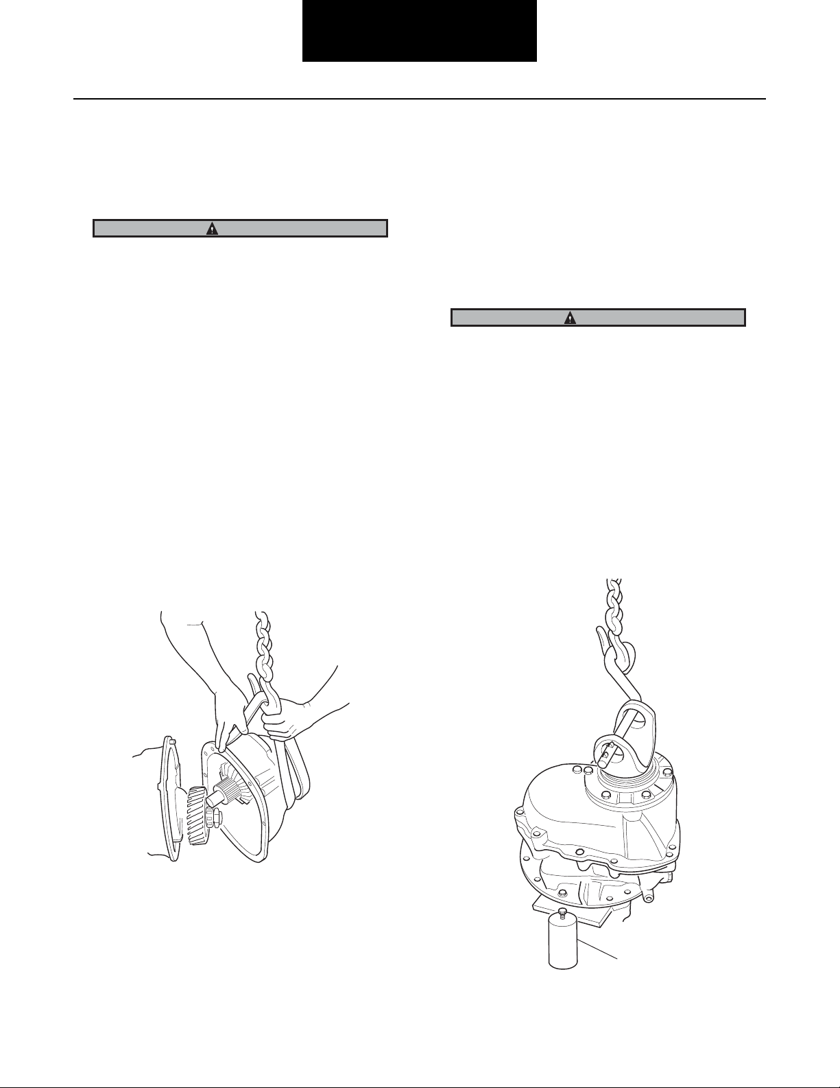
6. Remove PDU assembly.
7. Remove IAD assembly.
2. Wrap sling strap around power divider and attach to
chain hoist hook.
3. Tap on the sides of the cover at the dowel pins with a
mallet to create a space large enough to finish freeing
the cover from the dowel pins.
4. Pull the power divider forward until the input shaft
stub end is free of the output side gear, then remove
the assembly.
5. Remove IAD assembly.
1
1 - Carrier assembly stand
24
Page 29
Power Divider
Remove Power Divider from Differential Carrier (with carrier removed from axle housing)
Note: It is assumed that the differential carrier assembly has
been removed from axle housing prior to starting the following procedures:
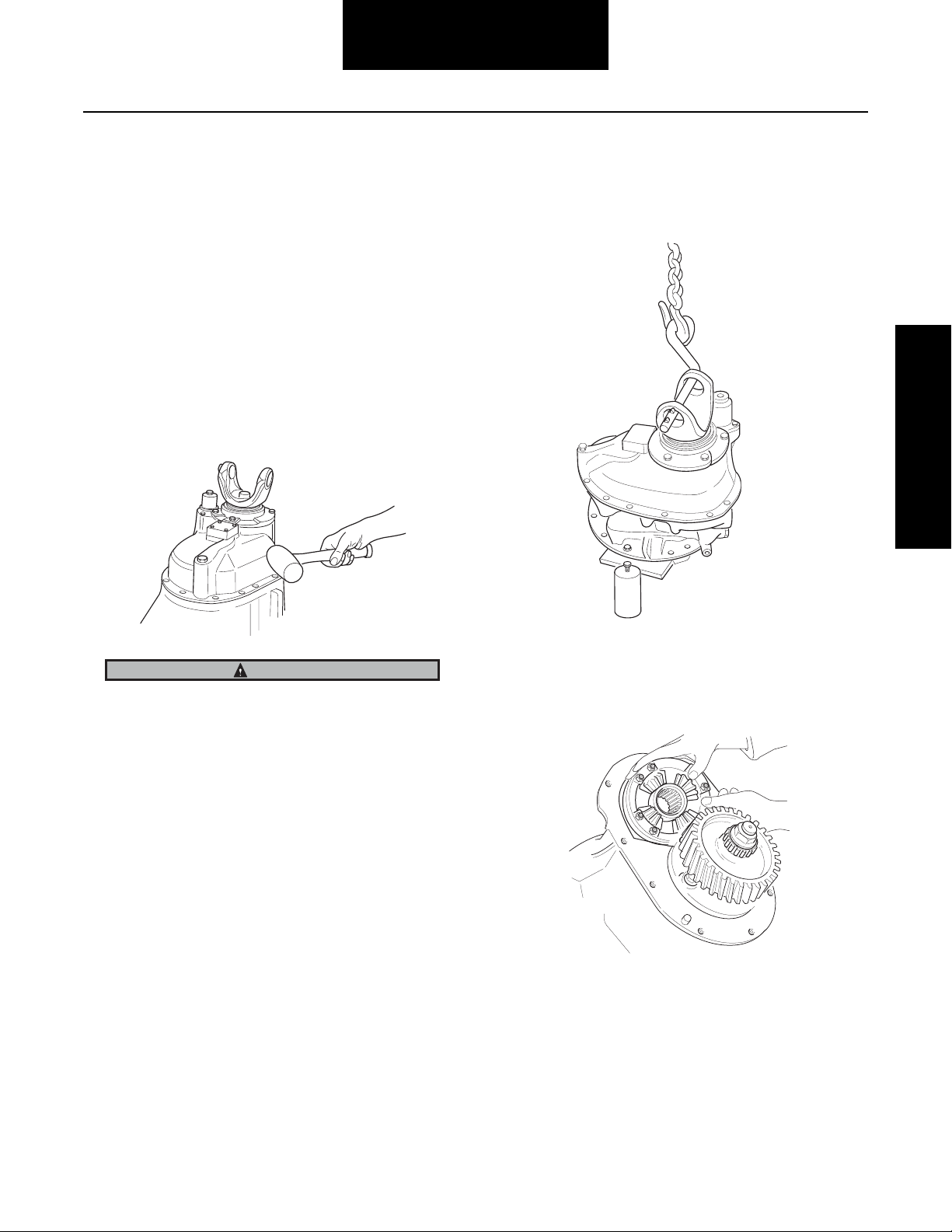
1. Mount differential carrier in repair stand. Loosen input shaft nut.
2. Remove power divider cover capscrews and lock
washers.
3. Fasten chain or strap to input yoke to remove power
divider.
Note: Power divider may not separate easily, strike the cover
near the dowel pin location with a mallet.
CAUTION
During removal of power divider, the inter-axle differential
may fall off input shaft from differential carrier. Exert caution to prevent damage of injury.
5. With chain hoist attached to input yoke, lift power divider off carrier.
Power Divider
Note: Lifting mechanism may create nicks or burrs on input
yoke. Remove if present.
6. Lift inter-axle differential assembly out of carrier or
off of output shaft side gear.
4. Tap the sides of the cover at the dowel pin location
with a mallet to loosen cover.
Note: Late model axles may be equipped with a spring and
thrust button mounted between the input and output
shafts, remove these parts.
25
Page 30
Power Divider
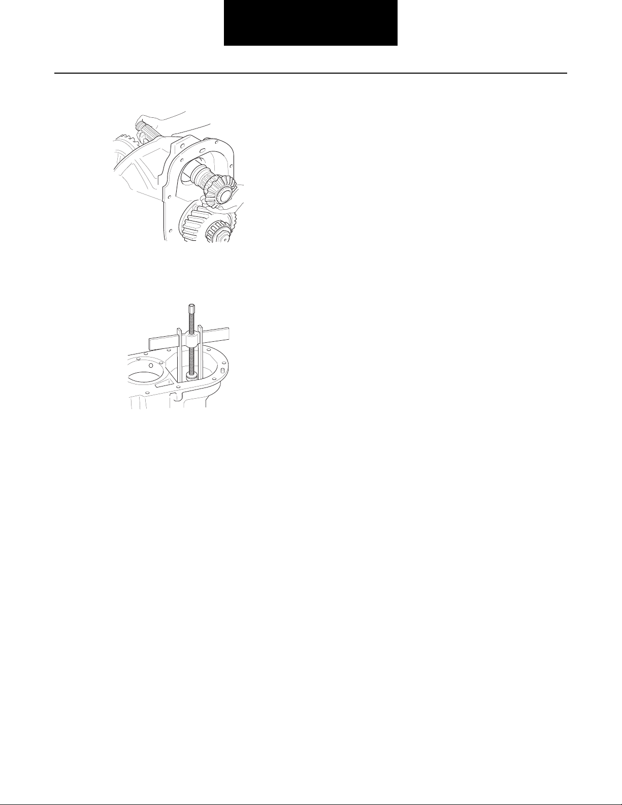
7. Tilt carrier and remove the output shaft assembly.
8. If removal of the output shaft side gear bearing cup is
necessary, use puller to remove bearing cup from
carrier
26
Page 31

Power Divider
Disassemble, Assemble and Overhaul the Power Divider
The power divider may be serviced with the carrier assembly
in or out of the axle housing.
Note: The following procedure assumes that the differential
carrier has been removed from the axle housing and that
the power divider has been removed from the carrier assembly.
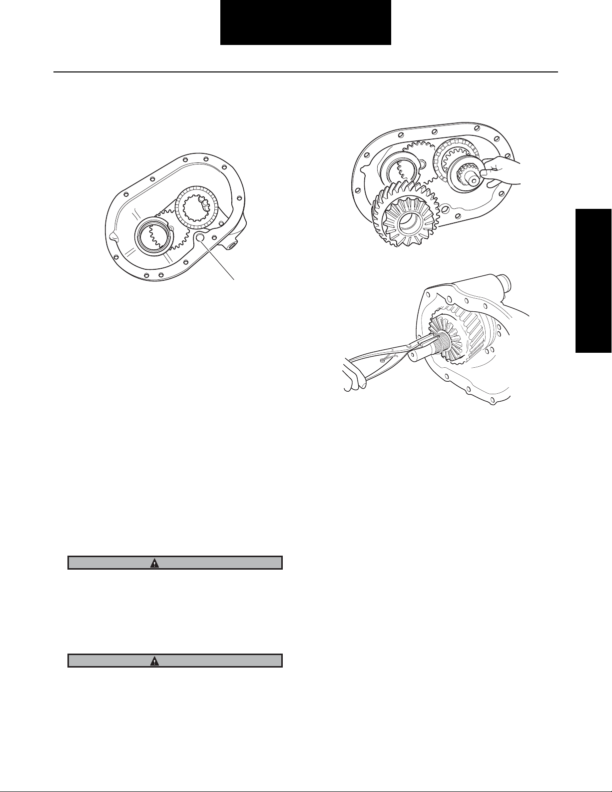
1. Late model axles may be equipped with a spring and
thrust button mounted between the input and output
shafts, remove these parts.
2. Remove output shaft and output side gear
Hammer: Use slipper to get under the cup and with a
hammer and drift from the back side of carrier tap out
bearing cup.
Power Divider
4. Remove snap ring from machined groove at rear of
input shaft.
3. If replacement of the output shaft side gear bearing
cup is necessary, use either of the following methods:
Weld: Place a weld bead around the inside of the cup,
when the weld cools the cup will fall out.
5. Slide helical side gear off input shaft.
6. Remove helical side gear thrust washer, and “D”
washer from shaft.
27
Page 32

Power Divider
7. At this point in disassembly, it is desirable to remove
lube pump drive gear nut. Hold input shaft yoke to secure drive gear, then loosen and remove drive gear
nut.
8. Remove input shaft nut and flat washer.
Note: Some models do not use flat washer as it is built into the
nut.
9. Remove yoke from input shaft using a puller tool.
TIP: A yoke puller tool may be made from the center
section of most gear puller tools, or may be purchased from your local tool distributor.
10. Remove input bearing cage, capscrews, input bearing cover and shim pack.
Note: Shift fork cannot be removed until lockout unit is disas-
sembled (see Differential Lockout Overhaul on page 20).
Shift fork push rod is secured to the lockout piston with
a nut.
12. Slide input shaft assembly out of cover.
13. Remove sliding clutch.
11. If input shaft bearing cup needs replacement, use either of the following recommended practices:
Weld: Place a weld bead around the cup, when the
weld cools the cup will fall out.
Drill: Drill a 1/4 inch size hole through the bearing
cover to the back side of the cup and use a punch to
remove the bearing cup.
1
1 - Sliding clutch
14. Remove input shaft bearing cone. Temporarily place
lockout sliding clutch over rear of input shaft, teeth
toward bearing cone. Place shaft in press and remove.
28
Page 33

Power Divider
Disassemble Power Divider Cover (For Axles with Input Shaft Tapered Roller Bearing)
Note: The drive on early pump models is equipped with a woo-
druff key. On late pump models the key is eliminated. The
drive shaft end has two machined flats and the drive gear
mounting hole is shaped to accommodate these flats.
1 - Lock nut
2 - Power divider cover
3 - Pipe plug
4 - Woodruff key
5 - O-ring
6 - Pump cover
7 - Capscrew
1
2
Power Divider
3
4*
13
12
11
10
8 - Lock washer
9 - Dowel pin
10 - Pump gears
11 - Magnetic strainer
12 - Expansion plug
13 - Pump drive gear
5
6
7
9
8
29
Page 34

Power Divider
1. With drive gear locknut previously removed and
working through input shaft bore, gently pry oil pump
drive gear from its shaft. See steps 5 and 6 for pump
disassembly.
2. For models built before February 1, 2000, remove
snap ring securing pinion outer support bearing race.
For models built after February 1, 2000, a design
change to a one piece roller bearing was implemented. Reference Dana Bulletin ABIB-0102 for more information.
WARNING
4. Unscrew and remove magnetic strainer from power
divider cover.
5. Remove oil pump cover capscrews and lock washers. Remove pump cover and o-ring.
Snap ring is spring steel and may pop out. Wear safety
glasses when removing.
3. Remove pinion outer support bearing race with suitable puller.
6. When woodruff key is used, remove key from gear
shaft. Remove pump gears from power divider cover.
30
Page 35

Power Divider
Assemble Power Divider Cover (For Axles with Input Shaft Tapered Roller Bearing)
1. Install pinion outer bearing race in power divider cover using a driver and a hammer.
2. For models built before February 1, 2000, install snap
ring to secure bearing race. For models built after
February 1, 2000, a design change to a one piece roller bearing was implemented. Reference Dana Bulletin
ABIB-0102 for more information.
WARNING
4. Install o-ring in pump cover, making sure o-ring is
seated firmly in body. If removed, install dowel pins.
Install pump cover on power divider cover and secure
with capscrews and lock washers. (See Torque Chart
on page 107).
Power Divider
5. Install pump drive gear. Install drive gear on pump
shaft end. Hand tighten drive gear nut.
Snap ring is spring steel and may pop out. Wear safety
glasses when installing.
3. Install pump gears in power divider cover (position
gear with long shaft in opening adjacent to input
shaft).
Note: Some pump drive shafts use a woodruff key. When key
is used, place key in shaft slot. Position gear on shaft engaging key. Then install gear with driver and hammer.
31
Page 36

Power Divider
6. Press input bearing cone on input shaft.
1 - Press
2 - Plate
3 - Drive Seal
4 - Input shaft bearing cone
5 - Input shaft
8. If bushing removal is needed, the bushings must exit
from the thrust washer side of the helical gear.
1
1
2
3
4
1 - Remove bearing from helical gear
9. Install bushings in helical side gear. Bushings must
5
be installed from thrust washer side of gear. See illustration for dimensional tolerances.
Note: Starting in March 1995, helical side gears are designed
with a shoulder step that helps prevent bushing walkout.
The inner bushing must be installed from the thrust
washer side of the helical gear against the shoulder step.
1 - Press
2 - Plate
3 - Drive sleeve
4 - Input shaft bearing cone
5 - Input shaft
7. Press bearing cup in input bearing cover.
1 - Input bearing cage
1
1 - Step added
1
2
3
4
1
1
5
1/32"
6
1 - Press
2 - Sleeve
3 - First bushing (press to shoulder step)
4 - Shoulder
5 - Sleeve
6 - Second bushing (recess 1/32”)
32
Page 37
Power Divider
10. Check expansion plug in power divider cover to make
sure it is in place and firmly seated. If loose, seat by
tapping with a hammer. Replace plug if necessary.
1
1 - Expansions plug
11. Install shift fork in power divider cover.
12. Install lockout cylinder assembly if removed. See Differential Lockout on page 20.
13. Place sliding clutch in power divider cover, engaging
clutch with shift fork. Position clutch teeth toward helical side gear.
14. Slide input shaft into power divider cover. Engage
shaft splines in lockout sliding clutch. Install bearing
spacer on input shaft. Use only on DS440-P, DS460P, DS480-P.
Snap ring is spring steel and may pop off. Wear safety glasses when installing.
Power Divider
16. Install magnetic strainer in power divider cover.
Torque to 40-60 lbs. ft. (54-81N•m).
15. Install input bearing cover and shims.
Note: Input shaft end-play must be adjusted after power divid-
er is assembled to differential carrier. For easier adjustment, temporally install input bearing cage cover and
tighten capscrews finger tight. See page 10 for End-play
Adjustment.
IMPORTANT
For axles with spring and thrust button between input shaft
and output shaft: For preliminary adjustment of input shaft
end play, install a 0.045" (0.024 mm) shim pack under bearing cover. See Axial Spring and Spring Button Adjustment
Section.
WARNING
Slide “D” washer over input shaft up to base of sliding clutch
splines. Install bronze thrust washer. Install helical side
gear. Secure with snap ring.
33
Page 38

Inter-axle Differential
Power Divider
1
2
3
6
8
4
5
7
1 - Case half
2 - Spider
3 - Bushing (use on models built before November 1, 1991)
4 - Side pinion
5 - Thrust washer
6 - Bolt
7 - Case half
8 - Lock nut
34
Page 39

Power Divider
Disassemble Inter-axle Differential
1. Punch mark differential case halves for correct position during reassembly.
2. Remove lock nuts and bolts. Separate case halves
and remove thrust washers, side pinions, bushings
and spider.
Note: Side pinion bushings are not used on tandem models
equipped with lube pumps built after November 1, 1991.
Use when originally equipped.
Assemble Inter-axle Differential
1. Install bushings, side pinions and thrust washers on
inter-axle differential spider. Pre-lube all components
at time of assembly.
Power Divider
1
1
1 - Punch marks
2. Install spider assembly in one differential case half,
align punch marks and install other case half. Secure
assembly with bolts and lock nuts. Torque to 17-23
lbs. ft. (23-31 N•m).
Note: Side pinion bushings are not used on tandem models
equipped with lube pumps built after November 1, 1991.
Use when originally equipped.
35
Page 40

Power Divider
Output Shaft Assembly
*Bushing removed from production axles in September 1994.
Output shafts with P/N 129016 do not use bushings.
1
1 - Output shaft
2 - Bushing
3 - O-rings
4 - Bearing cup (mounted in carrier)
5 - Bearing cone
2
3
6 - Side gear
7 - Axial spring
8 - Thrust button
9 - Snap ring
4
5
6
7
9
8
36
Page 41

Power Divider
Disassemble Output Shaft
WARNING
Snap ring is spring steel and may pop off. Wear safety glasses when removing.
1. Mount shaft assembly in vise, using brass vise jaw
protectors. Remove snap ring, side gear and bearing
cone assembly.
2. Remove output shaft o-rings. If replacement is necessary, remove bushing mounted in end of output
shaft.
Assemble Output Shaft
Note: Lubricate parts with gear lube during assembly.
1. Press bearing cone on output shaft side gear.
Power Divider
CAUTION
Provide protection against possible gear teeth damage during press operation.
2. Mount output shaft in a vise. Lubricate and install orings. If removed, install bushing in end of output
shaft.
Note: Output Shaft Bushings: In September 1994, a bushing-
less output shaft design change was implemented on
production 461, 521 and 581 model axles. Replace bushings only if originally equipped.
3. Remove bearing cone from side gear using press and
split-type puller.
Note: Tandem Axles built after September 1994 are equipped
with bushingless output shafts. Verify output shaft design before attempting to install a bushing.
WARNING
Snap ring is spring steel and may pop off. Wear safety glasses when installing.
3. Install side gear and bearing cone assembly. Install
snap ring, be careful not to over stretch the snap ring
when installing it into the shaft.
37
Page 42

Power Divider
Install Power Divider on Differential Carrier (with carrier assembled to axle housing)
Note: Lubricate all parts before installation.
1. If removed, install axle housing cover and output
shaft bearing. For instructions, see Installation of Forward Axle Housing Cover and Output Shaft Bearing
Parts on page 14.
2. If output shaft was removed, lubricate o-rings, then
install shaft assembly in differential carrier and housing cover. Lubricate seal lip. Make sure yoke is clean
and dry, then install yoke and self-locking nut. Torque
nut to 840-1020 lbs. ft. (1139-1383 N•m).
3. Insert axial spring and thrust button in the end of the
output shaft
4. Install inter-axle differential on output shaft side gear
(with nuts facing away from side gear).
5. Use silicone rubber gasket compound on differential
carrier mating surface.
1
2
3
1
1 - Input shaft
2 - Thrust button (Part #51228)
3 - Axial spring (Part #51238)
4 - Output shaft
Note: Late model axles may be equipped with axial spring and
thrust button mounted between input and output shafts.
See page 43.
38
4
1
1 - Dowel pin
Note: Gasket compound will set in 20 minutes. Install power
divider before compound sets or reapply.
CAUTION
During installation of the power divider, the inter-axle differential may fall from the carrier. Exert caution to prevent
damage or injury.
Page 43

Power Divider
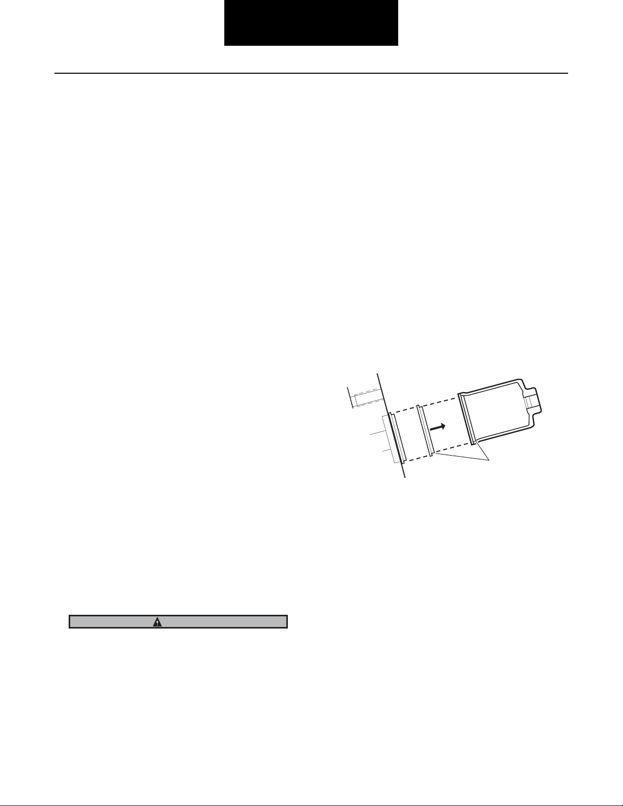
6. Make certain dowel pins are installed in carrier, then
install power divider assembly.
1
1 - Dowel pin
TIP: During installation, rotate input shaft to engage
input shaft splines with inter-axle differential. After
assembly output shaft should turn when input shaft
is rotated, and output shaft should turn independently from the input shaft.
8. Check and adjust input shaft end play. With power divider assembled to differential carrier, check end play
with dial indicator. End play should be 0.003" to
0.007". If necessary, adjust (see page 43). After end
play is within specifications, complete assembly procedures as follows:
Power Divider
9. Connect main driveline and inter-axle driveline.
10. Connect all applicable lines:
• IAD lockout
• Differential lock shift unit
11. Fill axle to proper lube level (see Lube Fill Capacities
on page 104).
IMPORTANT
TIP: The use of two guide pins in the carrier mating
surface will help align the PDU cover and aid in installation. Guide pins may be made from 9/16"-12 UNC
bolts approximately four inches long with the heads
removed.
7. Install power divider capscrews. Torque hex head
capscrew to 110-125 lbs. ft. (149-169 N•m) and
socket head capscrew to 115-125 lbs. ft. (155-169
N•m).
When the axle has been disassembled or the housing,
gears, axle shafts or wheel equipment replaced, check axle
assembly for proper differential action before operating vehicle. Wheels must rotate freely and independently.
39
Page 44

Power Divider
Install Power Divider on Differential Carrier (with carrier removed from axle housing)
The following instructions pertain to installation of power divider on differential carrier with carrier removed from axle
housing.
1. If output shaft side gear bearing cup was removed,
press bearing cup in carrier. Use a press and appropriate sleeve or use a brass drift and a mallet. Tap
bearing cup into its bore making certain cup is evenly
and firmly seated.
2. Lubricate o-rings, then install output shaft assembly
in carrier.
3. Insert axial spring and thrust button in the end of the
output shaft.
4. Install inter-axle differential assembly on output shaft
side gear (with nuts facing away from output shaft
side gear).
5. Apply silicone gasket compound on carrier mating
surface.
2
3
1
1 - Input Shaft
2 - Thrust button (Part #51228)
3 - Axial spring (Part #51238)
4 - Output shaft
Note: Early model axles may not be equipped with axial spring
and thrust button. If your axle was not equipped with
these parts, go to step 4.
40
4
Note: Gasket compound will set in 20 minutes. Install power
divider before compound sets or reapply.
6. Attach chain hoist to input yoke and install power divider assembly. During installation, rotate input shaft
to engage input shaft splines with inter-axle differential. After installation, rotate input shaft again. Output
shaft should turn when input shaft is rotated if assembly is correct.
Page 45

Power Divider
Note: Lifting mechanism may create nicks and burrs on input
yoke. Remove if present.
7. If removed, install dowel pins in carrier. Install power
divider cover capscrews and lock washers placing
sockethead capscrew at location shown on drawing.
Torque capscrews to appropriate specification. (See
Torque Chart on page 107).
2
1
2
1 - Socket head capscrew
2 - Dowel pin
Note: For power dividers equipped with an input shaft tapered
roller bearing, adjust shaft end play after power divider
cover is assembled to differential carrier. Refer to page
43.
Power Divider
41
Page 46

Power Divider
Measure and Adjust Input Shaft End-Play
Note: After power divider overhaul and installation on carrier,
check and adjust input shaft end-play.
Input Shaft End Play Chart
New or Rebuild
with new parts
0.003" to 0.007"
Acceptable End-Play Tolerances when measuring as a regular maintenance procedure with axle in truck.
Up to 0.060" with
over 100,000
miles or 1 year
service off-road
Up to 0.040" with
less than 100,000
miles or 1 year
service on-road
NOTE: Because of manufacturing variations in individual parts, correctly adjusted end-play could vary 0.010", after
the unit is rotated.
NOTE: If end-play exceeds limits, disassemble power divider and replace worn
parts.
Without Input Shaft Axial Spring Thrust
Button
CAUTION
In September 1988, a axial spring and thrust button were
added between the input and output shafts. End-play tolerances are the same for axles with or without this spring and
button. However, end-play measurement procedure is different than described here. Refer to page 44 of this manual
for procedure variances.
2. Reinstall bearing cover without shims. Hold in position with hand pressure and measure clearance between power divider cover and bearing cover, using a
feeler gauge.
3. The bearing cover clearance measured in Step 2 plus
0.005" will equal shim pack thickness required for desired end-play (rebuild with new parts). Add 0.015" to
shim pack for rebuild with used parts.
4. Install shim pack and bearing cover. Install capscrews. Torque screws to 75–85 lbs. ft. (101–115
N•m). Make sure shims are flat with no kinks or
bends.
5. Install yoke. Tighten nut snugly. Tap end of input
shaft lightly to seat bearings.
6. Check input shaft end-play with dial indicator positioned at yoke end of input shaft. Move input shaft axially and measure end-play. If end-play is correct, seal
shim pack with Dana approved RTV compound to
prevent lube leakage. Then torque input shaft nut.
The correct end-play when new parts are used in overhaul is
0.003" to 0.007", with reused parts the maximum is 0.14".
1. Remove input shaft nut, flat washer and yoke. Remove input bearing cover capscrews. Remove bearing cover (and shim pack if installed).
42
Page 47

Power Divider
With Input Shaft Axial Spring Thrust Button
In September 1988, Spicer added an axial spring and thrust
button between the input and output shafts. The addition of
these parts reduces shaft end play movement by loading the
shafts axially in the direction of the yoke. End play tolerances
are the same for axles with or with out the new spring and
thrust button. However, end play measurement procedure is
different as described below.
Note: As of September 1994, production and service output
shafts for the D461, 521 and 581 models are no longer
produced with a bushing in the end of the shaft. The
shafts can be identified by part number, see Output Shaft
Assembly on page 38 for more information.
1
2 3
3. Build up a 0.045" (0.024 mm) thick shim pack and
place shim pack and bearing cover on power divider
cover.
Power Divider
4. Install the U-bracket on bearing cover, using two
bearing cover capscrews. Install all other cover capscrews and torque to 75-85 lbs. ft. (101-115 N•m).
1
2
4
1 - Thrust button
2 - Axial spring
3 - Output shaft
4 - Input shaft
Input Shaft Axial Spring
1. Fabricate a U-bracket from 1 in. flat stock (minimum
thickness 0.125") as specified in the illustration.
2. If axle is assembled, first remove input shaft nut, flat
washer and yoke.
3
4
5
6
1 - Bearing cover capscrew
2 - Lock washer
3 - Fabricated U-bracket
4 - Inner bearing cover
5 - Input bearing cover shim(s)
6 - Input shaft
43
Page 48

Power Divider
5. Position a dial indicator on the end of the input shaft.
3
2
1
1 - Pry bar
2 - U-bracket
3 - Dial indicator
4 - Input shaft
Remove shim to decrease end-play
Measured end-play (Step 6) 0.015" – 0.015"
Desired end-play (New Parts) 0.003” to 0.007”
Remove shims to provide desired end-
0.012” to 0.008”
play
4
11. To add or remove shims, remove input shaft nut, flat
washer and yoke. Remove capscrews, lock washers
and bearing cover. Add or remove shims as required.
12. Install bearing cover and capscrews. Seal shim pack
with Dana approved RTV compound to prevent lube
leakage then torque input shaft capscrews 75–85
lbs. ft. (101–115 N•m).
13. Install yoke.
14. Install new yoke nut with the pre-applied thread adhesive compound. Tighten the nut to the specified
torque 840–1020 lbs. ft. (1148–1383 N•m).
6. Lift up on pry bar to compress input shaft.
7. Insert a pry bar through the U-bracket with the end of
the bar resting on the end of the input shaft.
8. Zero the dial indicator and lift up on the pry bar to
move the input shaft axially until it bottoms out within
the bearing cover. Measure the end-play.
9. If the end-play is acceptable, remove U-bracket and
bearing cover. Seal shim pack to prevent lube leakage. Reinstall bearing cover and capscrews. Torque
capscrews to 75-85 lbs. ft. (101-115 N•m). Continue
axle assembly as necessary.
10. If end-play is incorrect, change shim pack size as follows:
Add shims to increase end-play
Desired end-play (New Parts) 0.003" to 0.007"
Measured end-play (Step 6) 0.001” – 0.001”
Add shims to provide desired end-play 0.002" to 0.006"
44
Page 49

Carrier Assembly
Forward Axle Carrier Assembly (Single Speed) with Diff. Lock - Parts Exploded View
4
52 53 54 56 57 58 55 6 1 5
59
7
2
3
1
DIFFERENTIAL
& RING GEAR
14
8
9
10
11
19 15
13
1
12
16
17
18
20
Carrier Assembly
21
30
RH
22
23 24
33
29 31 32 35 34 38 36 37 34 35 28 27 26 25
LH
45
Page 50

Carrier Assembly
76 77
62
60
78
61
79 80 81 82 83
106
63
64 65
66
91
INTER-AXLE
DIFFERENTIAL
ASSEMBLY
68
67
92
93
84 85 86 88 8990
69
105
71
87
74
70
73
75
70
72
46
39 31 40
41
42
43 45
LUBE PUMP
104 103 95
444647
43
50
48
40
91
49
94 97 98 99
96
51
100
101
102
Page 51

Carrier Assembly
1 - Differential carrier & bearing caps
2 - Bearing capscrew
3 - Flat washer
4 - Lockwire
5 - Dowel bushing
6 - Bearing cap adjuster lock (RH)
7 - Capscrew
8 - Bearing cap adjuster lock (LH)
9 - Cotter pin (LH)
10 - Expansion plug (upper)
11 -Expansion plug (lower)
12 - Filler plug
13 - Shift fork shaft
14 - Carrier cover dowel pun
15 - Shift unit mounting stud
16 - Shift fork seal & spring assembly
17 - Flat washer
18 - Stud nut
19 - Shift fork & roller assembly
20 - Shift unit assembly
21 - Sliding clutch
22 - Differential bearing adjuster (RH)
23 - Differential bearing cup (RH)
24 - Differential bearing cone (RH)
25 - Differential bearing adjuster (LH)
26 - Differential bearing cup (LH)
27 - Differential bearing cone (LH)
28 - Differential case (plain half)
29 - Differential case (flanged half)
30 - Differential case capscrew
31 - Ring gear & drive pinion
32 - Bolt
33 - Nut
34 - Differential side gear
36 - Side pinion
37 - Side pinion thrust washer
38 - Spider
39 - Pinion pilot bearing
40 - Pinion bearing cone
41 - Pinion bearing spacer washer
42 - Pinion bearing spacer
43 - Pinion bearing cup
44 - Pinion bearing cage
45 - Pinion bearing cage shim
46 - Lock washer
47 - Bearing cage capscrew
48 - Pinion helical gear
49 - Outer pinion support bearing (one
piece)
50 - Pinion shaft end nut
51 - Pinion nut spring pin
52 - Output shaft nut
53 - Output shaft washer
54 - Rear bearing retaining washer
55 - Axle housing cover
56 - Output shaft oil seal
57 - Bearing snap ring
58 - Output shaft bearing
59 - Filler plug
60 - Output shaft
61 - Output shaft bushing
62 - Output shaft O-ring
63 - Output shaft bearing cup
64 - Output shaft bearing cone
65 - Output shaft side gear
66 - Side gear snap ring
67 - Output shaft compression spring
68 - Output shaft thrust bearing
69 - Inter-axle differential assemble
70 - Inter-axle differential case half
71 - Case bolt
72 - Case nut
73 - Side pinion
74 - Side pinion thrust washer
75 - Spider
76 - Helical side gear snap ring
77- Helical side gear
78 - Helical side gear bushing
79 - Helical side gear thrust washer
80 - Helical side gear “D” washer
81 - Lockout sliding clutch
82 - Input shaft
83 - Input shaft bearing cone
84 - Input shaft bearing cup
85 - Input cover shim
86 - Input bearing cover
87 - Bearing cover capscrew
88 - Input shaft oil seal
89 - Input shaft nut washer
90 - Input shaft nut
91 - PDU carrier cover
92 - Carrier cover capscrew
93 - Lock washer
94 - Pipe plug
95 - Expansion plug
96 - Magnetic filter screen
97 - Pump gear & shaft assembly
98 - Cover O-ring
99 - Lube pump cover
100 - Lock washer
101 - Cover capscrew
102 - Cover dowel pin
103 - Pump drive gear
104 - Drive gear locknut
105 - Air-operated lockout assembly
106 - Shift fork & push rod assembly
Carrier Assembly
47
Page 52

Carrier Assembly
Rear Axle (Single Speed) - Parts Exploded View
10 11 12 15 18 20 21 17 18 13 15 12 11 10
16 17 19 14 14
243 6
5
6 5 1 1 22 23 24 29 31 32
8 9272628 25 26 23 30 33
13
48
Page 53

Carrier Assembly
1 - Differential carrier & bearing caps
2 - Bearing capscrew
3 - Flat washer
4 - Lockwire
5 - Bearing cap adjuster lock
6 - Cotter pin
7 - Dowel bushing
8 - Ring gear thrust screw
9 - Thrust screw jam nut
10 - Differential bearing adjuster
11 - Differential bearing cup
12 - Differential bearing cone
13 - Ring gear & drive pinion
14 - Bolt and nut
15 - Differential case (flanged half)
16 - Differential case capscrew
17 - Differential side gear
18 - Side gear thrust washer
19 - Side pinion
20 - Side pinion thrust washer
21 - Spider
22 - Pinion pilot bearing
23 - Pinion bearing cone
24 - Pinion bearing spacer
25 - Pinion bearing cage
26 - Pinion bearing cup
27 - Pinion bearing spacer washer
28 - Pinion bearing cage shim
29 - Bearing cage capscrew
30 - Oil seal
31 - Input yoke
32 - Flat washer
33 - Pinion nut
Carrier Assembly
49
Page 54

Carrier Assembly
Forward Axle (Two Speed) - Parts Exploded View
18
16
17
1
3
2
5
4
7
6
8
36
15
13
14
12
11
9
10
19
20
3031
32
Dual Range Axles
33
Planetary Double
Reduction Axles
21
29
22
26
34
23
28
35
24
25
27
40
37
38
39
Planetary Double
Reduction Axles
41
42
43
44
45
46
51
47
52
48
49
53
54
50
59
56
55
57
61
60
58
63
62
64
65
50
Page 55

Carrier Assembly
1 - Nut
2 - Washer (used on DT461-P, DT652P,
DP461-P, DP652-P)
3 - Yoke
4 - Bearing retainer washer (used on
DT440-P, DT485-P, DP440-P, DP650-P)
5 - Oil seal
6 - Snap ring
7 - Bearing & sleeve
8 - Filler plug
9 - Capscrew
10 - Lockwire
11 - Dowel bushing
12 - Adjuster lock
13 - Bearing cap
14 - Dowel bushing
15 - Capscrew
16 - Lockwire
17 - Flat washer
18 - Bearing cap
19 - Cotter pin
20 - Adjuster lock
21 - Expansion plug
22 - Shift fork shaft
23 - Filler plug
24 - Differential carrier
25 - Dowel pin
26 - Expansion plug
27 - Nut
28 - Lock washer
29 -Seal spring
30 - Seal
31 - Stud
32 - Shift fork
33 - Shift fork cover
34 - Lock washer
35 - Capscrew
36 - Differential & ring gear
37 - Sliding clutch (dual range only)
38 - Retainer
39 - Sun gear
40 - Bearing adjuster
41 - Bearing cup
42 - Bearing cone
43 - Ring gear nut
44 - Gear support case
45 - Ring gear
46 - Thrust washer
47 - High-speed clutch plate
48 - Idler pinion pin
49 - Idler pinion
50 - Differential assembly
51 - Differential case with pins
52 - Thrust washer
53 - Side gear
54 - Spider
55 - Thrust washer
56 - Side pinion
57 - Plain differential assembly
58 - Capscrew
59 - Thrust washer
60 - Gear support case
61 - Washer
62 - Ring gear bolt
63 - Bearing cone
64 - Bearing cup
65 - Bearing adjuster
Carrier Assembly
51
Page 56

Carrier Assembly
Rear Axle (Two Speed) - Parts Exploded View
Dual Range
RT440, RT460,
RT480, RT485
Planetary
Double
Reduction
RP440, RP460,
RP480, RP485,
RP580, RP650
53
7
4
46
47
49
52
51
50
11
10
9
8
48
14
12
13
37
36
15
17
18
16
42
44
41
34
35
19
33
20
55
56
39
40
64
38
32
65
68
43
45
Dual Range
RT461, RT521,
RT601, RT651
Planetary
Double
Reduction
RP461, RP521,
RP581, RP601,
RP651, RP652
31
30
25
69
29
28
Planetary Double
Reduction Axles
21
22
71
72
27
26
24
23
73
52
6
5
59
58
3
2
57
61
60
62
63
66
70
67
Page 57

Carrier Assembly
1 - Cotter pin
2 - Adjusting lock
3 - Bearing cap
4 - Capscrew
5 - Flat washer
6 - Dowel bushing
7 - Lockwire
8 - Bearing cap
9 - Adjusting lock
10 - Dowel bushing
11 - Lockwire
12 - Capscrew
13 - Differential carrier
14 - Expansion plug
15 - Shift fork shaft
16 - Shift fork
17 - Stud
18 - Seal
19 - Seal spring
20 - Shift unit
21 - Shift fork cover
22 - Lock washer
23 - Capscrew
24 - Retainer
25 - Sun gear
26 - Sliding clutch (dual range)
27 - Bearing adjuster
28 - Bearing cup
29 - Bearing cone
30 - Ring gear nut
31 - Gear support case (LH)
32 - Ring gear
33 - Thrust washer
34 - High-speed clutch plate
35 - Idler pinion
36 - Idler pinion pin
37 - Differential assembly
38 - Differential case with pins (LH)
39 -Thrust washer
40 - Side gear
41 - Spider
42 - Side pinion
43 - Thrust washer
44 - Side gear
45 - Thrust washer
46 - Plain differential case (RH)
47 - Capscrew
48 - Thrust washer
49 - Gear support case (RH)
50 - Washer
51 - Ring gear bolt
52 - Bearing cone
53 - Bearing cup
54 - Bearing adjuster
55 - Lock washer
56 - Nut
57 - Expansion plug
58 - Pilot bearing
59 - Drive pinion
60 - Bearing cone
61 - Spacer washer
62 - Bearing spacer (variable)
63 - Bearing cup
64 - Bearing cage shim
65 - Bearing cage
66 - Lock washer
67 - Capscrew
68 - Bearing cup
69 - Bearing cone
70 - Oil seal
71 - Yoke
72 - Flat washer (use on RT461, RT651,
RP461, RP652)
73 - Pinion nut
Carrier Assembly
53
Page 58

Disassemble Differential Carrier (with power divider removed)
Carrier Assembly
Dual range axles only
1. Remove shift fork seal and spring.
2. Remove expansion plugs.
3. Working at the lower (or small) plug hole, drive out
the shift fork shaft.
4. Disengage shift fork yoke from sliding collars.
5. Remove clutch and shift fork.
Planetary double reduction axles
A sun gear is used in place of sliding clutch gear. To remove
sun gear:
1. Remove capscrews and the retainer which holds gear
in position.
2. Remove sun gear.
Models with Ring Gear Thrust Bolt
Note: If the carrier model has a ring gear thrust bolt installed,
it must be backed away from the ring gear before you can
remove the wheel differential.
1. Back off thrust bolt jam nut.
2. Back out thrust bolt from the carrier until the end of
the bolt is flush with the inside of the carrier casting.
This will allow enough clearance between the ring
gear and the carrier pilot web.
1
54
2
3
1 - D-head carrier or front carrier
2 - Thrust bolt
3 - Thrust bolt jam nut
Page 59

Carrier Assembly
Remove Wheel Differential (All Standard
Models)
Note: If gear set is to be reused, check tooth contact pattern
and ring gear backlash before disassembling differential
carrier. When checking backlash, a yoke or helical gear
must be installed and torqued to get an accurate reading.
Best results are obtained when established wear patterns
are maintained in used gearing. Omit this step if the gear
set is to be replaced.
1. Mount differential carrier in repair stand.
3. Cut lockwire. Remove capscrews, flat washers and
bearing caps. Back off bearing adjusters and remove
adjusters and bearing cups.
Carrier Assembly
4. Using a chain hoist, lift ring gear and differential assembly out of carrier.
Note: For easier disassembly, loosen but do not remove pinion
(self-locking) nut. Forward axle pinion is equipped with
slotted nut, remove roll pin with a pin punch then loosen
nut.
2. Punch mark bearing caps. If reusing gear set, also
punch mark bearing adjusters for reference during
assembly.
1
1 - Punch marks
55
Page 60

Carrier Assembly
Remove Pinion Assembly
1. Forward Axle: Remove pinion nut. Remove helical
drive gear using puller. Remove helical gear spacer
(D440-P and D560-P only).
Note: For easier disassembly, loosen but do not remove pinion
(self-locking) nut. Forward axle pinion is equipped with
slotted nut, remove roll pin with a pin punch then loosen
nut.
2. Remove pinion bearing cage capscrews. Remove
pinion and cage assembly from carrier. Remove shim
pack.
IMPORTANT
Forward and Rear Axle: If gear set is to be reused, keep pinion bearing cage shim pack intact for use in reassembly. If
the original shims cannot be reused, record the number and
size of shims in the pack.
Do not allow pinion to drop on hard surface.
3. Forward Axle: Pilot Bearing Sleeve (Early Models
Only): If replacement is necessary, remove capscrews, locks and pilot bearing sleeve from carrier.
56
Page 61

Drive Pinion - Parts Exploded View
Front Axle Pinion Assembly
1
2
3
4
5
Drive Pinion
6
7
10
8
9
11
12
13
16
14
15
17
Drive Pinion
1 - Pinion pilot bearing
2 - Pinion
3 - Pinion bearing cone - inner
4 - Pinion bearing spacer
5 - Bearing spacer variable
6 - Pinion bearing cup - inner
7 - Shim
8 - Pinion bearing cage
9 - Pinion bearing cup - outer
Rear Axle Pinion Assembly
10 - Capscrew
11 - Pinion bearing cup - outer
12 - Helical gear spacer
13 - Pinion helical gear
14 - One piece bearing
15 - Slotted pinion nut
16 - Roll pin
17 - Pinion self locking nut
20
21
22
23
24
25
26
27
30
31
32
33
34
28
29
35
18 - Pinion pilot bearing
19 - Pinion
20 - Pinion bearing cone - inner
21 - Pinion bearing spacer
22 - Bearing spacer variable
23 - Pinion bearing cup - inner
24 - Shim
25 - Pinion bearing cage
26 - Lock washer
27 - Capscrew
28 - Pinion bearing cup - outer
29 - Pinion bearing cone - outer
30 - Oil seal
31 - Yoke
32 - Flat washer
33 - Pinion nut
57
Page 62

Disassemble and Overhaul Drive Pinion
Drive Pinion
The following procedures cover both forward and rear differential drive carrier assembly.
Note: Dana drive axles may be equipped with either “press-fit”
or “slip-fit” outer pinion bearings. Procedures are contained in this section for assembly of both types.
1. Rear Axle Pinion Yoke: Remove yoke.
2. If pinion nut was not loosened during earlier disassembly, clamp assembly in vise jaws, use brass pads
to prevent damage. Loosen and remove pinion nut
and flat washer. Remove yoke from pinion.
CAUTION
If pinion nut was not loosened during earlier disassembly,
clamp assembly in vise jaws, use brass pads to prevent
damage.
3. Loosen and remove pinion nut and flat washer. Remove yoke from pinion using an appropriate tool.
4. Forward and Rear Axle Pinion Bearing Cage:
• Press-fit. Press pinion out of bearing cage and
bearing cone.
6. Remove bearing spacer and spacer washers from
pinion.
7. Remove pilot bearing from pinion using a split-type
puller. Use two procedure steps to remove each bearing.
a. Mount puller vertically to separate the bearing.
This action will force puller halves under bearing
and start moving bearing off pinion.
1
1 - Press ram
• Slip-fit. For pinion with “slip-fit” bearing cone,
the cage, outer bearing and pinion can usually be
disassembled easily without a press. If difficulty
is experienced, use a press.
5. Rear Axle Pinion Oil Seal and Outer Bearing Cone:
Remove oil seal and bearing cone from cage. Discard
oil seal. Remove bearing cups with suitable puller.
b. Mount puller horizontally to press pinion out of
bearing.
58
Page 63

Drive Pinion
8. Remove inner bearing cone from pinion using a splittype puller. Use two procedure steps to remove each
bearing.
a. Mount puller vertically to separate the bearing.
This action will force puller halves under bearing
and start moving bearing off pinion.
b. Mount puller horizontally to press pinion out of
bearing.
Replace Pinion Bearing Cage Cups
1
Front
2
1 - Cup (outer)
2 - Bearing cage
3 - Cup (inner)
1. Remove cups.
Rear
3
2
Drive Pinion
1 - Press
2. Clean and inspect bearing cages for damage, nicks
and burrs.
1
1
2
1 - Press ram
2 - Sleeve must apply pressure to back face of outer bearing
cone
59
Page 64

Drive Pinion
3. Install inner and outer pinion bearing cups. Use a
press and an appropriate drive sleeve. Make certain
bearing cup is evenly and firmly seated.
4. Seat cups securely to shoulder. Check clearance between cup and bearing cage. Must be less than .001".
Adjust Pinion Bearing Preload
Trial Buildup
1. Assemble pinion bearing cage, bearings, spacer and
spacer washer (without drive pinion or oil seal). Center bearing spacer between two bearing cones. Lubricate bearing cups and cones.
1
2
3
4
5
6
1 - Bearing
2 - Cup
3 - Spacer washer
4 - Bearing spacer (variable size)
5 - Cage
6 - Cup
7 - Bearing
Note: When new gear set or pinion bearings are used, select
nominal size spacer from the specification chart. If original parts are used, use spacer removed during disassembly.
60
Page 65

Drive Pinion
2. With the bearings well lubricated, place the assembly
in the press. Position sleeve so that load is applied directly to the backface of the outer bearing cone.
1
2
3
1 - Press ram
2 - Sleeve must apply pressure to back face of outer bearing
cone
3 - Spring scale
3. Rotate pinion cage while applying press load (see
chart below) to the assembly and check rolling
torque. Wrap soft wire around the bearing cage, attach spring scale and pull. Preload is correct when
torque required to rotate the pinion bearing cage is
from 3–7 lbs. (2–3 kgs.).
Specifications for Pinion Bearing Trial Buildup Preload Test
Torque to Rotate Bearing Cage (w/o pinion seal)
10–20 lbs. in. (1.1–2.3 N•m)
Forward Axles and Rear Axles
Spring Scale Reading 3 - 7 lbs.
(2 - 3 Kgs.)
Press Loads 18.5 - 19.5 tons
(16.8 - 17.7 metric tons)
Nominal Bearing Thickness
spacer
CAUTION
0.185”
(4.699 mm)
Read only the torque value after the bearing cage starts to
rotate.
4. If necessary, adjust pinion bearing preload by changing the pinion bearing spacer. A thicker spacer will
decrease preload. A thinner spacer will increase preload.
IMPORTANT
Once correct bearing preload has been established, note the
spacer size used. Select a spacer 0.001” larger for use in
the final pinion bearing case assembly. The larger spacer
compensates for slight “growth” in the bearings which occurs when they are pressed on the pinion shank.
Drive Pinion
Do not assume that all assemblies will retain proper preload once bearing are pressed on pinion shank. FINAL PRELOAD TEST MUST BE MADE IN EVERY CASE.
61
Page 66

Drive Pinion
Final Buildup
Note: On rear axles, do not install oil seal in cage until bearing
preload is correctly adjusted.
IMPORTANT
After bearing cups are installed, preselect pinion bearing
spacer using the “trial buildup” procedure.
Note: During pinion bearing installation, locate each part in
same position that was used in “trial buildup” preload
test.
1. Press inner bearing cone on pinion.
3. Install bearing cage on drive pinion.
4. Press outer bearing cone on pinion.
IMPORTANT
To prevent bearing damage, spin cage while pressing outer
bearing on.
IMPORTANT
To prevent bearing damage, use suitable sleeve that only
contacts inner race of bearing cone.
2. Install preselected bearing spacer.
62
5. Apply clamp load to the pinion bearing cage assembly. Either install the yoke (or helical gear) and torque
the pinion nut to specifications or use the press to
simulate nut torque (see chart).
Page 67

Drive Pinion
Specifications for Pinion Bearing Final Buildup
Preload Test
Torque to Rotate Bearing Cage (w/o pinion seal)
15-35 lbs. in.(1.7–4.0 N•m)
Forward Axles Rear Axles
Spring Scale
Reading
5 - 12 lbs.
(2 - 5 kgs.)
Press Loads 18 - 21 tons
(16.3 - 18 metric tons)
Nut Torque 980 lbs. ft.*
(1,329 N•m)
840 - 1,020 lbs. ft.
(1,139 - 1,383 N•m)
*Torque nut to 980 lbs. ft. (1,329 N•m), then continue
tightening nut to align nut slot to nearest hole in pinion
shank.
Vise Method
a. If the yoke and nut are used, mount the assembly
in a vise, clamping yoke firmly.
6. Measure Pinion Bearing Preload: Use a spring scale
to test the assembly rolling torque. To use the spring
scale, wrap flexible wire around the bearing cage, attach the scale and pull. Preload is correct when
torque required to rotate the pinion bearing cage is
from 5–12 lbs.
CAUTION
Read only the torque value after the bearing cage starts to
rotate.
7. Adjust Pinion Bearing Preload: If necessary, adjust
pinion bearing preload. Disassemble the pinion bearing cage as recommended in this manual and change
the pinion bearing spacer. A thicker spacer will decrease preload. A thinner spacer will increase preload.
IMPORTANT
Use the correctly sized spacer. Do not use shim stock or
grind spacers. These practices can lead to loss of bearing
preload and gear or bearing failure.
Drive Pinion
1 - Vise
Press Method
a. If a press is used, position a sleeve or spacer so
1
that load is applied directly to the backface of the
outer bearing cone.
1
8. Press pilot bearing on pinion.
IMPORTANT
To prevent bearing damage, use suitable sleeve that only
contacts the inner race of bearing con.e
1 - Press
63
Page 68

Drive Pinion
9. Stake pilot bearing using staking tool. This is essential to retain the bearing.
10. Rear Axle Only: With pinion installed and bearing
preload adjustment complete, install oil seal. Use
properly sized installation tool as described on page
92 to prevent distortion.
Specification for Final Pinion Bearing Preload Test
(“Press-fit” Outer Pinion Bearings)
Nut Torque
Axle Models lbs. ft. N•m
Forward Axles
Self-Locking Nut 840 - 1020 1139 - 1383
Slotted Nut & Roll
Pin
Rear Axles 840 - 1020 1139 - 1383
* Torque nut to 980 lbs. ft.. (1329 N•m), then continue tightening nut to align nut slot to nearest hole in pinion shank.
11. Rear Axle Only: Prior to installation of yoke, make
sure yoke is clean and dry.
980* 1329*
1
2
3
1 - Tool
2 - Seal
3 - Bearing cage
12. Install yoke.
13. Install and tighten the nut to the specified torque:
840–1020 lbs. ft. (1140–1383 N•m).
Note: Use of a torque multiplier is recommended.
TIP: If you can't get the correct torque on yoke nut,
try torquing the nut with the truck wheels on the
ground and with the axle shafts installed.
Note: Forward axle pinion helical gear and bearing: These
parts are installed after pinion installation in carrier (see
Install Helical Gear and Pinion Outer Support BearingForward Axle Only on page 65).
64
Page 69

Install Drive Pinion Assembly
Drive Pinion
1. Forward Axle Only: Place shim pack on carrier making sure holes are properly aligned. Make sure shims
are flat with no kinks or bends.
2. Rear Axle Only: Place shim pack on carrier making
sure lube holes are clear.
Note: Use a dummy yoke (if available) in place of helical gear.
This will result in easier disassembly and reassembly
during carrier adjustments.
Drive Pinion
Note: Do not install cotter pin until carrier adjustments are
completed.
4. Rear Axle Drive Pinion: Install pinion assembly. Install bearing cage capscrews and lock washers.
Torque capscrews to 160–176 lbs. ft. (217–239
N•m).
1
1 - Lube slots
Note: If gear set is to be reused, install same quantity and size
of shims removed during disassembly. When installing a
new gear set, use nominal shim pack indicated.
Nominal Shim Pack
Axle in mm
Forward 0.024 0.610
Rear 0.023 0.584
3. Forward Axle Drive Pinion Only: Install drive pinion
assembly. Install bearing cage capscrews and lock
washers. Torque capscrews to 155–175 lbs. ft.
(210–237 N•m).
65
Page 70

Drive Pinion
Install Helical Gear and Pinion Outer Support Bearing - Forward Axle Only
After February, 2000
1
2
Note: After differential adjustment is complete or if dummy
yoke was used, remove nut and yoke. Then continue to
assemble pinion as follows:
1. On D440-P and D460-P only, install helical gear spacer. Install helical gear on pinion using driver and hammer.
4
One Piece Support Bearing
1 - Slotted nut and roll pin
2 - Support bearing race
3 - Helical gear
4 - Helical gear spacer
Before February, 2000
1
2
4
5
7
Two Piece Support Bearing
1 - Support bearing race
2 - Snap ring
3 - Slotted nut and roll pin
4 - Self locking nut
5 - Pinion outer support bearing
6 - Helical gear
7 - Helical gear spacer (D440-P, D460-P only)
3
2. Install pinion outer support bearing using driver and
hammer.
3
3. Install self-locking nut or slotted nut. Torque nut
6
properly (see chart), using a suitable fixture to hold
helical gear.
Note: On axles equipped with slotted nut and roll pin, do not
install roll pin until carrier adjustments are completed.
If the power divider was built before February 2000, continue
with Step 4.
66
Page 71

Drive Pinion
4. If removed, install bearing race in power divider cover, using driver and hammer.
5. Install snap ring to secure bearing race.
Drive Pinion
WARNING
Snap ring is spring steel and may pop out. Wear safety
glasses when installing.
IMPORTANT
Torque to 980 lbs. ft. (1329 N•m), then continue tightening
nut to align slow with the nearest hole in pinion shank. Install roll pin.
Torque Chart
Pinion Self-Locking Nut
Size lbs. ft. N•m
1-3/4 - 12 840 - 1020 1139 - 1383
Pinion Slotted Nut and Roll Pin
Size lbs. ft. N•m
1-3/4 - 12 980* 1329*
* Torque nut to 980 lbs. ft. (1,329 N•m), then continue tightening nut to align nut slot to nearest hole in pinion shank.
67
Page 72

Wheel Differential Assembly
Wheel Differential Assembly - Parts Exploded View
Single Reduction Differential
73458
12 3 45
Differential Lock
1 - Sliding clutch
2 - Diff. lock differential bearing adjuster
3 - Differential bearing cup
4 - Differential bearing cone
5 - Nut (ring gear)
6 - Diff. lock differential case (flanged half)
7 - Differential bearing adjuster
8 - Differential case flange half
9 - Ring gear
9101112131415 1211 16 17 4 3 7
6
10 - Bolt
11 - Side gear thrust gear
12 - Differential side gear
13 - Side pinion thrust washer
14 - Spider
15 - Side pinion
16 - Differential case (plain half)
17 - Differential case capscrew
68
Page 73

Wheel Differential Assembly
y
Planetary and 2 - Speed Differential
1
2 3 4 5 6 7 8 9 10 11 12 13 14 15 4 3 2
17
16
1 - Sliding clutch (dual range only)
2 - Differential bearing adjuster
3 - Differential bearing cup
4 - Differential bearing cone
5 - Ring gear nut
6 - Gear support case
7 - Ring gear
8 - Thrust washer
18 19 20 21 22 23 24 25 26
9 - High speed clutch plate
10 - Idler pinion pin
11 - Idler pinion
12 - Differential assembly
13 - Thrust washer
14 - Gear support case
15 - Ring gear bolt and washer
16 - Retainer
Wheel Differential
Assembl
17 - Sun gear
18 - Differential case with pins
19 - Side gear thrust washer
20 - Differential side gear
21 - Side pinion
22 - Spider
23 - Side pinion thrust washer
24 - Plain differential case
69
Page 74

Wheel Differential Assembly
Disassemble, Overhaul and Assemble Wheel Differential (Forward and Rear Axles)
For Single Reduction Differential Case
Disassemble Wheel Differential
Note: For Dual Reduction Differential Case see page 73.
IMPORTANT
During following procedure, place differential assembly on
malleable surface to prevent damage when ring gear falls
off its mounting position.
1. Remove nuts and bolts fastening ring gear to differential cases, allowing gear to fall free. If gear does not
fall, tap outer diameter with soft mallet to loosen.
4. Lift out spider, side pinions and thrust washers.
5. Remove remaining side gear and thrust washer.
6. Remove bearing cones from case halves using suitable puller.
7. Remove bearing cone from plain case half in two
steps:
a. Mount puller vertically to split bearing. This ac-
tion will start moving bearing off case.
2. Punch mark differential cases for correct location
during reassembly. Remove capscrews and lift off
plain differential case half.
1
1 - Punch marks
3. Lift out side gear and thrust washer.
b. Mount puller horizontally to remove cone.
8. Remove bearing cone from flanged case half using
suitable puller.
70
Page 75

Wheel Differential Assembly
y
Overhaul and Assemble Wheel Differential
IMPORTANT
To prevent bearing damage, use suitable sleeve that only
contacts the inner race of the cone. A used bearing race
would be a suitable tool. This tool should have a slit cut if
the ID is the same as the flange OD.
1. Press new flange half bearing cones on differential
case halves.
2. Press new plain half bearing cones on differential
case halves.
6. Place side gear and thrust washer on side pinions.
7. Align punch marks and install plain case half. Install
capscrews and tighten. See Torque Chart on page
106. Check differential for free rotation by turning
side gear hub.
1
1 - Punch marks
8. Install ring gear. Secure with bolts and nuts. Torque
nuts to 180-220 lbs. ft. (224-298 N•m)
Wheel Differential
Assembl
Note: Flange half differential cases were redesigned starting
with production axles built in January 1997. New style
ring gear bolts are also required with the new style flange
case, the torque specification for this bolt is different
3. Place thrust washer and side gear in flanged differential case.
4. Lubricate all differential parts.
5. Assemble side pinion and thrust washers on spider.
Place this assembly in flanged differential case. Rotate gears and check for proper mesh.
than the old 126219 bolt.
9. Lower assembled differential assembly into the carrier using a hoist and a strap. Be careful not to damage
the differential bearings lowering the assembly.
10. Install the bearing cup and bearing adjuster to the
flange half side first.
11. Install the bearing cup and bearing adjuster to the
plain half side. Use a long screwdriver or bar to lift the
differential up while installing the cup and bearing adjuster.
71
Page 76

Wheel Differential Assembly
Planetary and 2-Speed Models (Forward and Rear Axles)
1
2 3 4 5 6 7 4 3 8
109
12
1 - Differential case capscrew
2 - Differential case (plain)
3 - Side gear thrust washer
4 - Differential side gear
5 - Side pinion thrust washer
6 - Side pinion
7 - Spider
8 - Differential case with pins
9 - Differential bearing adjuster
10 - Differential bearing cup
11 - Differential bearing cone
12 - Ring gear bolt
13 - Gear support case (large)
14 - Support case thrust washer
15 - Idler pinion pin
16 - Idler pinion
18 19
LHRH
17 - High speed clutch plate
18 - Ring gear
19 - Gear support case (small)
20 - Ring gear nut
21 - Sliding clutch (dual range axles)
22 - Sun gear
23 - Sun gear retainer
11 10 9 21 22 2314171615141311
20
72
Page 77

Wheel Differential Assembly
y
Disassemble Dual Reduction Differential Case
Note: For Single Reduction Differential Case see page 68.
1. Remove nuts and bolts fastening ring gear and support cases.
2. Remove small support case and thrust washer.
6. Invert differential assembly to remove idler pins, then
remove idler pinions.
Wheel Differential
Assembl
7. Punch mark differential cases for correct location in
reassembly. Remove capscrews and separate case
halves.
8. Lift out thrust washer and side gear.
3. Remove ring gear.
Note: A soft-faced hammer or mallet may be required to dis-
lodge gear from its mounting.
4. To remove differential assembly, place support case
assembly on a bench or on the floor. Position case on
its side, then slowly roll the case and slide differential
assembly out of the case.
5. Remove thrust washer from support case.
9. Lift out spider, side pinions and side thrust washers.
73
Page 78

Wheel Differential Assembly
10. Remove inner side gear and thrust washer.
11. First, try to lift off high-speed clutch plate by hand. If
it cannot be removed easily, press off plate as follows:
Note: Holes are provided in case to enable removal of bearing
cone with a pin punch. Tap alternately through each hole
until cone is removed.
WARNING
When using a drift, punch or similar tool, wear safety glasses.
a. Insert properly sized adapters (round metal
stock) into two idler pin holes and invert the case
assembly in a press. The clutch plate should be
down. The adapter length should provide space
for removal of the plate.
b. Use bar stock to block the center hole in the
clutch plate and press against it with the press
ram.
c. Continue to press until the plate breaks loose
from the plate dowel pins.
12. Remove bearing cones from support cases using
suitable puller.
74
Page 79

Wheel Differential Assembly
y
Assemble Dual Reduction Differential Case
Note: Lubricate internal parts with gear lube during reassem-
bly.
1. Press bearing cones on support cases.
IMPORTANT
To prevent bearing cone damage, use suitable sleeve that
only contacts the inner race of the cone.
Pressing Bearing Cone on Large Support Case
2. Position high-speed clutch plate with chamfered end
of clutch teeth toward idler pinions. Press clutch plate
on case.
Wheel Differential
Assembl
IMPORTANT
It is important that the ends of the dowel pins are recessed
1/8 inch below surface of the clutch plate. If pins extend beyond plate surface, press pins to proper depth. Don’t press
them in too far.
Pressing Bearing Cone on Small Support Case
15 DEGREE
CHAMFER
35 DEGREE
CHAMFER
POSITION
35 DEGREE
SIDE OF
PLATE
TOWARD
CASE
HIGH-SPEED
CLUTCH PLATE
DOWEL
PIN
CASE
THRU-
HOLE
RECESS
1/8 in.
75
Page 80

Wheel Differential Assembly
3. Place thrust washer and side gear in differential case.
4. Assemble side pinions and thrust washers on spider.
Place this assembly in differential case.
5. Place side gear and thrust washer in position on side
pinions.
6. Align punch marks and place plain case on case (with
pins). Install capscrews. Torque screws to 116-130
lbs. ft. (157-176 N•m).
76
Note: Turn side gear hub to check for free differential rotation.
Rotation may require up to 50 lbs. ft. (65 N•m).
7. Install idler pins and pinions.
Page 81

Wheel Differential Assembly
y
8. Place thrust washer in support case.
9. During installation of ring gear, temporarily use two
bolts in mounting holes to assure bolt hole alignment. Place ring gear on support case, then remove
two bolts.
11. Install thrust washer and small support case over differential assembly.
Wheel Differential
Assembl
12. Carefully install ring gear bolts, making certain flat on
bolt head is seated against the outside diameter of the
support case. Install nuts and torque to 110-130 lbs.
ft. (149-176 N•m).
10. To install differential assembly, place support case
and ring gear assembly on bench or the floor. Position case on its side. Carefully lift and slide differential
assembly into case. Engage idler pinions with ring
gear teeth to complete the installation.
Note: During differential installation, be sure thrust washer
stays in its proper mounting position.
Note: Temporarily install sliding clutch (or sun gear) and
check planetary for free rotation.
77
Page 82

Wheel Differential Assembly
Install Differential–Forward and Rear Axles
Note: Lubricate bearings during the following assembly proce-
dures.
1. Place ring gear and differential assembly in carrier.
Carefully lower the assembly until bearing cones rest
on carrier.
2. Install bearing cup and bearing adjuster to the flange
half side first.
3. Lubricate the differential bearings. Install bearing cup
and bearing adjuster to the plain half side. Use a long
screwdriver or bar to lift the differential up while installing the cup and bearing adjuster.
4. With bearing adjusters and cups assembled to carrier, the carrier assembly is now ready for adjustment
of bearing preload, ring gear backlash and gear tooth
contact (see page 79).
78
Page 83

Wheel Differential Assembly
y
Measure and Adjust Carrier Assembly
Adjust Backlash and Preload
1. Turn the flange half bearing adjuster in until the ring
gear contacts the pinion (zero backlash) then back
the adjuster out two notches of the adjuster lugs.
1
1 - Flange half
2 - Plain half
2. Tighten the plain half adjuster until the bearing cup
just starts to turn, this is a zero bearing preload.
3. Tighten the plain half adjuster two lug notches. Start
with the notch at the top, count two notches counterclockwise on the adjuster, turn the adjuster so that
the notch is facing straight up. You now have a two
notch preload.
2
2
1
Wheel Differential
Assembl
1 - Lugs
2 - One notch
4. Use a rubber mallet to make certain that both bearing
adjusters are fully seated.
5. Measure backlash. Make sure it is within specification of .006"–.018".
TIP: To give yourself room to adjust contact pattern,
set it between .010"–.012".
79
Page 84

Wheel Differential Assembly
Change Backlash Setting
If you have too much backlash the ring gear needs to move
closer to the pinion. Back off the plain half adjuster, count the
number of notches you back it off, each notch equals about
.003" of backlash.
IMPORTANT
In order to maintain the differential bearing preload you will
need to turn the flange half bearing adjuster the same
amount in the same direction. If you need more backlash reverse this procedure.
1. Install carrier bearings caps and torque carrier cap
bolts to 370–430 lbs. ft. (501–583 N•m)
2. Recheck backlash: if the bearing adjusters were not
in straight or fully seated the backlash will change.
a. Used Gearing: Reset to backlash recorded be-
fore disassembly.
b. New Gearing: Backlash should be between
0.006 and 0.018".
Measure Ring Gear Runout
Measure Ring Gear Total
1. Measure ring gear total radial runout. (Indicator reading should not exceed .010").
2. Measure ring gear total backface runout (Indicator
reading should not exceed .010").
3. Check ring gear tooth contact pattern. Paint ring gear
teeth and check tooth contact pattern. Correct tooth
patterns. Checking and adjusting procedures are on
page 80.
4. Install bearing adjuster cotter pins.
5. Install retainer.
80
Page 85

Wheel Differential Assembly
y
Adjust Tooth Contact Pattern
Adjust Ring and Pinion Tooth Contact Pattern
2
1
1 - Face width
2 - Tooth depth
3 - Heel
4 - Top land
5 - Root
6 - Toe
Note: Rear axle gearing is shown in the following instructions.
Correct tooth contact patterns and adjustments are the
same for forward and rear axles.
1. Identify if new or used gearing.
2. Check tooth contact pattern (new or used gearing).
New Gearing - Correct Pattern
Paint six ring gear teeth 180° apart with marking compound
and roll the gear to obtain a contact pattern. The correct pattern
is slightly below center on the ring gear tooth with lengthwise
contact up off the toe. The length of the pattern in an unloaded
condition is approximately one-half to two-thirds of the ring
gear tooth in most models and ratios.
The pattern could vary in length and should cover 1/2 tooth or
more (face width). The pattern should be evenly centered between tooth top land and root and should be up off the tooth
toe.
3
4
5
6
Used Gearing - Correct Pattern
Used gearing will not usually display the square, even contact
pattern found in new gear sets. The gear will normally have a
“pocket” at the heal end of the gear tooth. The more use a gear
has had, the more the line becomes the dominant characteristic of the pattern.
Adjust used gear sets to display the same contact pattern observed before disassembly. A correct pattern is up off the toe
and centers evenly along the face width between the top land
and root. Otherwise, the length and shape of the pattern are
highly variable and is considered acceptable as long as it does
not run off the tooth at any point.
Pattern along the face width could be longer
Adjust Contact Pattern
If necessary, adjust the contact pattern by moving the ring gear
and drive pinion.
• Ring gear position controls the backlash. This adjustment moves the contact pattern along the face width
of the gear tooth.
• Pinion position is determined by the size of the pinion
bearing cage shim pack. It controls contact on the
tooth depth of the gear tooth.
These adjustments are interrelated. As a result, they must be
considered together even though the pattern is altered by two
distinct operations. When making adjustments, first adjust the
pinion, then the backlash. Continue this sequence until the pattern is satisfactory.
Wheel Differential
Assembl
81
Page 86

Wheel Differential Assembly
Adjust Pinion Position
If the gear pattern shows incorrect tooth depth contact, change
drive pinion position by altering the shim pack. Used gears
should achieve proper contact with the same shims removed
from the axle at disassembly.
Note: Check ring gear backlash after each shim change and
adjust if necessary to maintain the 0.006" to 0.018" specifications.
If the pattern is too close to the top land of the gear tooth, remove pinion shims. Move pinion toward the ring gear.
If the pattern is too close to the root of the gear tooth, add pinion shims. Move pinion away from the ring gear.
3. Return to adjuster on teeth side of ring gear and tighten adjuster until it contacts the bearing cup.
4. Continue tightening the same adjuster 2 or 3 notches
and recheck backlash.
If the pattern is concentrated at the heel (too far up
the tooth), move the ring gear toward the pinion to
decrease backlash.
5. Loosen the bearing adjuster on the teeth side of the
ring gear several notches.
6. Tighten the opposite adjuster one notch.
7. Return to adjuster on teeth side of ring gear and tighten adjuster until it contacts the bearing cup.
8. Continue tightening the same adjuster 2 or 3 notches
and recheck backlash.
Adjust Ring Gear Position (Backlash)
If the gear pattern shows incorrect face width contact, change
backlash by adjusting the ring gear.
If the pattern is too close to the edge of the tooth toe, move the
ring gear away from the pinion to increase backlash
1. Loosen the bearing adjuster on the teeth side of the
ring gear several notches.
2. Loosen the opposite adjuster one notch.
82
Page 87

Wheel Differential Lock
Wheel Differential Lock - Parts Exploded View
1
2
1 - Shift fork seal and spring assembly
2 - Shift fork and roller assembly
3 - Sliding clutch
4 - Differential bearing adjuster
5 - Differential case (flanged half)
3
4 5 4
Wheel Differential Lock
83
Page 88

Wheel Differential Lock
Install and Adjust Wheel Differential Lock, Dual Range Shifters
1. For planetary double reduction axles (on backface
side of ring gear), install sun gear and retainer, then
install capscrews that fasten both retainer and adjuster lock capscrews. Tighten screws to correct torque
(see chart), and lockwire all capscrews.
3
2
1
Differential Bearing
Capscrew Size
13/16-10 (8) 370 - 430 501 - 583
Bearing Adjuster Lock
and Sun Gear Retainer
Capscrew Size
Torque Chart Cap
Grade lbs. ft. N•m
Grade lbs. ft. N•m
4
5
Planetary Double Reduction Axle
1 - Capscrew
2 - Sun gear retainer
3 - Bearing adjuster
4 - Sun gear
5 - Lock wire
2. For dual range axles and differential lock: Position
shift fork in carrier opening, then install sliding clutch
3. With clutch installed, engage shift fork yoke with
clutch collar. Then install shift fork shaft. Install expansion plugs to seal openings.
5/8-11 (5) 160 - 176 216 - 238
Install and Adjust Ring Gear Thrust Bolt
1. Thread thrust screw into the carrier until firm contact
with the backface of the ring gear is made.
2. Loosen the thrust screw 1/4 turn to obtain the correct
adjustment of .020" (.50 mm) clearance between gear
face and screw. Tighten jam nut, holding thrust screw
stationary with a wrench, torque jam nut 150–190.
lbs. ft. (203–258 N•m).
3. Recheck to assure minimum clearance during full rotation of ring gear.
1
Installing Shift Fork Shaft
4. Install shift unit seal and spring.
84
2
3
1 - D-head carrier or front carrier
2 - Thrust bolt
3 - Thrust bolt jam nut
Page 89

Piston Air Shift Unit
Wheel Differential Lock
12
9
10
13
14
15
17
18
19
Wheel Differential Lock
20
35 1 4 2 6 8 23
24 25
1 - Cover assembly
2 - Cover bearing
3 - Screw and washer assembly
4 - Cover gasket
5 - Cover plug
6 - Actuating lever
7 - Clevis pin
8 - Actuating lever, pin, and block assembly
9 - Shift housing cover
10 - Seal ring
11 - Cover bolt
12 - Lock nut
13 - Lock nut
16
7
26
21
11
22
14 - Washer
15 - Piston
16 - Felt piston oiler (strip)
17 - Piston o-ring
18 - Grommet
19 - Push rod
20 - Compression spring
21 - Piston stop
22 - Housing assembly
23 - Housing bearing
24 - Switch
25 - Nylon washer
26 - Wiring harness
85
Page 90

Air Shift Unit Replacement
Wheel Differential Lock
Removal of Shift Unit
1. Disconnect air lines at shift unit cover.
2. Disconnect the wiring harness and remove selector
switch from the housing cover.
3. Remove nuts, flat washers and piston air shift unit
from the differential carrier.
Note: When shift unit is removed, provide container to catch
oil that escapes from reservoir.
4. Remove shift fork seal and spring assembly.
Note: Dana Service Manual AXSM-0029 for overhaul proce-
dures on air shift units is available.
Air Shift Unit Installation
1. Lubricate shift fork.
2. Slide shift fork seal and spring assembly over fork
and seal onto the shift unit carrier studs.
3. Place shift unit on mounting studs and make certain
shift fork actuating lever engages slot in shift fork.
4. Install flat washers and stud nuts.
• Torque 55-61 lbs. ft. (74-82 N•m)
Note: When axle is installed in vehicle, fill shift unit housing to
level of filler plug with SAE 10 oil [1.5 oz. (50 ml)]. Coat
threads of filler plug with sealer and install plug.
5. Thread selector switch in air shift unit and reconnect
wiring harness
6. Connect air lines to shift unit cover.
86
Page 91

Air Shift Unit Overhaul
Wheel Differential Lock
Disassemble Unit
1. Remove capscrews, lock washers, cover and gasket
from housing. Drain lubricant.
2. Remove bolts, lock nuts, cover at piston end of housing. Remove o-ring.
CAUTION
During the following procedure, the piston will pop out of
housing under spring pressure. Exercise caution to prevent
possible injury.
3. Remove lock nut, flat washer, and piston from push
rod. Remove o-ring and felt oilers from piston.
1
2
1 - O-ring
2 - Actuating lever assembly
3 - Piston
4 - Felt oilers
5 - Compression spring
6 - Shift unit housing
7 - Piston rod
8 - Clevis pin
3
4
5
6
7
8
4. Remove compression spring and piston stop from
bore of shift unit housing.
1
2
3
1 - Compression spring
2 - Piston
3 - O-ring
5. Remove clevis pin, then remove push rod from shift
unit housing. Remove o-ring from push rod.
6. Remove actuating lever and pin from shift unit housing. Do not disassemble actuating lever.
3
2
1
Wheel Differential Lock
4
1- Actuating lever
2 - Shift fork swivel pin
3 - O-ring
4 - Actuating lever pin
5 - Bearing
5
87
Page 92

Wheel Differential Lock
Parts Inspection
Shift Fork Seal: Inspect shift fork seal for defects and tight fit
on shift fork. A spring is used to assure a closer fit of seal
around shift fork. If this spring is not present on axle being serviced, install one when reassembling unit.
O-rings, Felt Oilers and Gasket: Replace o-rings, felt oilers
and cover gasket when piston air shift unit is disassembled for
repair.
Compression Spring: Inspect spring for distortion, cracks or
other visual defects. Replace a faulty spring.
Actuating Lever and Pins: Inspect lever pins and bearings for
worn or grooved condition. Inspect actuating lever and push
rod for worn or elongated holes at point where they are connected. Replace faulty parts.
Piston: Inspect piston friction surface for worn, grooved or
damaged condition which will affect the piston movement in
cylinder. Replace a faulty piston.
88
Page 93

Wheel Differential Lock
Assemble Unit
Note: Prior to assembly, the piston felt oilers should be soaked
in SAE 10 oil for one hour. Lubricate o-rings with a highviscosity silicone oil or barium grease o-ring lubricant.
1. Assemble pin to actuating lever and install this assembly in shift lever unit housing.
2. Assemble o-ring and piston to push rod and fasten
with flat washer and lock nut. Tighten nut to a torque
of 120-150 lbs. in. (14-17 N•m). Install felt oilers and
o-ring in piston.
CAUTION
During the following procedure using a press, make certain
components are properly aligned in press to prevent possible personal injury or damage to parts.
3. Insert piston stop and compression spring in shift
unit housing. Place piston and push rod assembly in
housing. Position housing assembly in arbor press.
1
2
3
4
5
4. Apply pressure to piston until actuating lever is in
alignment with push rod end. Install clevis pin. Release press.
2
1
3
4
5
1 - Actuating lever assembly
2 - Press
3 - Shift unit housing
4 - Push rod
5 - Clevis pin
5. Place cover gasket in position on shift unit housing
then install cover and bearing assembly and fasten
with capscrew and lock washers. If necessary, use a
sealer on threads of capscrews to prevent any leaking. Tighten screws to a torque of 90-110 lbs. in. (1012 N•m).
6. Place o-ring in groove of shift unit housing, then install housing cover and secure with bolts and lock
nuts. Tighten lock nuts evenly to a torque of 108-132
lbs. in. (12-15 N•m).
Wheel Differential Lock
1 - Press
2 - Piston
3 - Piston lock nut
4 - Compression spring
5 - Actuating lever assembly
7. Fill shift unit with SAE 10 oil or automatic transmission fluid (see Lubrication) when axle is installed in
vehicle.
89
Page 94

Wheel Differential Lock
Lubrication
Lubricant: Use SAE 10 motor oil* for temperature above 0°F
(–18°C). For temperatures below 0°F (–18°C), mix three parts
of SAE 10 motor oil with one part of kerosene. This cold weather mixture can be safely used up to 32°F (0°C).
Note: Commercially available automatic transmission fluid
may be used in place of SAE 10 motor oil. Automatic
transmission fluid can be used for all temperatures. Do
not mix kerosene with automatic transmission fluid.
Lubricant Check and Level: Each 20,000 miles or six months,
remove pipe plug in shift unit housing cover to check lubricant
level. Lube should be level with bottom of filler hole [1.5 oz.
(50 ml)].
Lubricant Change: At least once a year remove shift unit housing cover and drain old lubricant. Wash parts thoroughly and
air dry. Reinstall cover. Remove pipe plug in cover. Fill through
pipe plug opening until lube is level with bottom of filler hole.
90
Page 95

Housing and Rear Cover Assembly
y
Housing and Rear Cover Assembly - Parts Exploded View
1
2
3
4
5
1 - Rear cover
2 - Rear cover capscrew
3 - Fill plug
4 - Rear cover nut
5 - Lock washer
6 - Stud
7 - Dowel
8 - Jam nut - outer
9 - Locking ring
10 - Jam nut (inner)
7
17
16
13
15
12
Housing and Rear Cover
Assembl
14
Bolt on Rear Cover
6
10
9
8
20
11
18
19
11 - Axle housing
12 - Breather
13 - Breather hose
14 - Carrier capscrew
15 - Lock washer
16 - Nut
17 - Lock washer
18 - Stud
19 - Drain plug
20 - Axle shaft
91
Page 96

Seals
Replace Seal
Dana strongly recommends using seal drivers when installing
new seals. Use the proper driver to make sure that the seal is
square and installed to the proper depth.
Seals
WARNING
Due to the resiliency of the plastic driver, hammer rebound
may occur when the seal is seated. Keep clear of the hammer rebound path!
CAUTION
Oil seals can be easily damaged prior to installation. Use
care when handling the new seal to prevent damage or contamination. Leave the seal in its package until installation.
On new yokes, leave the protector on the yoke until it is installed on the shaft to prevent damage or contamination.
1. Inspect axle end-play at the yoke (see page 10). Service if beyond specified limit.
2. Remove the old yoke using appropriate tool. A yoke
puller tool may be made from the center section of
most gear puller tools, or may be purchased from
your local tool distributor.
1
1 - Yoke puller tool
6. Handle the seal by its outside diameter avoiding any
contact with the seal lips. During installation, use the
proper driver to make sure that the seal is mounted
properly.
7. Use a rubber mallet to drive the seal tool in until the
flange bottoms on the housing cover bore face. The
flange will locate the seal at the proper depth.
Guidelines for Reusing Yoke
CAUTION
Do not use the yoke if it has any damage on the seal surface
(nicks or scratches).
3. Remove seal. Use care when removing the old seal to
prevent damage to the housing seal bore.
4. Inspect the seal bore area for any damage (nicks,
gouges, corrosion). Carefully remove any slight damage with a crocus cloth. Clean the bore area to remove any loose debris.
CAUTION
Do not use any silicone or permatex-type bore sealant with
this seal.
5. Remove the new seal from its package and install
with the proper driver:
Service kit #217590
D-Input-Use driver #210749 with inert 210750 only
D-Output-Use insert #210751
R-Pinion-Use driver #210749 only
92
The surface of the yoke and the lips of the seal form a critical
interface which retains the axle's lubricant while sealing the
axle from outside contaminants. The condition of the yoke
hub's surface is a very important factor in determining seal life.
Carefully inspect the seal surface area of the yoke hub for signs
of wear and damage. Do not reuse the yoke if there is noticeable wear, such as heavy grooving, beyond normal polishing
from the seal lips.
Note: Do not rework the yoke with abrasives such as emery
paper or crocus cloth. Clean the surface of the yoke as
necessary using chemical cleaners. Remove all trace of
the chemicals from the yoke after cleaning.
CAUTION
Do not use wear sleeves. Wear sleeves increase the yoke
hub surface diameter and cause premature seal wear and
repeat seal failure.
Page 97

Seals
New Welded D-Housing Cover
Lube Quantity Difference
0 (zero)
Standout of Output Shaft Yoke
Length increased by 6 mm (.25"), this should not have any significant impact on inter-axle driveline length or drive line angles.
Service Kit 217414
D - Input D - Output R - Pinion
Location
Interchangeability of Parts
A cross reference chart of “OLD” axle housing to “NEW” axle
housings with welded on covers will be published in a separate
bulletin. The bolt on D-Housing covers will remain available for
service.
Seals
126917
Tool
Old Seal
New Seal
126917
128706
D - Input D - Output R - Pinion
126917
93
Page 98

Housing Breather
Housing Breather
Install New Axle Housing Breather (Metal
and Plastic)
Dana uses an axle housing breather that consists of a fitting,
hose and clamp assembly. This breather design has improved
resistance to water ingestion, clogging caused by dirt, ice or
snow buildup around the base of the breather. See installation
instructions below (all views from rear).
1. Install fitting in breather hole.
2. Tighten fitting finger tight.
• Plastic only: tighten until one thread is showing.
4. Insert hose onto fitting, long end down.
3. Using a 3/4" wrench:
• Metal only: rotate the fitting at least 1/2 turn until nipple points to rear. Torque to 5 lbs. ft.
5. Push hose firmly against fitting. Rotate hose to point
down.
94
Page 99

Wheel End Seal - Parts Exploded View
Wheel End Seal
Wheel End Seal
1
2
3
1 - Installation tool
2 - Seal
3 - Rear hub
95
Page 100

Remove and Overhaul Wheel End Seal
WARNING
Wheel End Seal
Never work under a vehicle supported by only a jack. Always
support vehicle with stands. Block the wheels and make sure
the vehicle will not roll before releasing the brakes.
IMPORTANT
Wheel end seals can be easily damaged during handling.
Leave the seal in its package until installation to prevent
damage or contamination.
1. Remove outer bearing and wheel.
2. Remove oil seal.
3. Remove inner bearing.
4. Remove old wear sleeve (2-piece design only) with a
ball peen hammer and discard.
CAUTION
Do not cut through the old wear sleeve. Damage to the housing may result.
5. Inspect spindle journal and hub bore for scratches or
burrs. Recondition with an emery cloth as required.
Install Wheel End Seal
1. Before installation, lubricate the following with the
same lubricant used in the axle sump.
• Inner bearing
• Wheel seal (follow the directions provided by the
seal supplier)
2. Place seal on installation tool.
3. Drive seal with installation tool onto hub.
Note: Deep gouges can be repaired by filling gouge with hard-
ening gasket cement and smoothing with emery cloth.
6. Clean hub cavity and bearing bores before reassembly. Be sure to remove contaminants from all recesses and corners.
7. Clean bearings thoroughly with solvent and examine
for damage. Replace damaged or worn bearings.
CAUTION
Always use the seal installation tool specified by the seal
manufacturer. Using an improper tool can distort or damage
the seal and cause premature seal failure.
96
 Loading...