

Page 1
Spicer
®
CTIS
(
Central Tire Inflation System
Troubleshooting Guide
AXTS0015
)
July 2010
Page 2
General Information
General Information
The description and specifications contained in the service
publication are current at the time of printing.
Dana reserves the right to discontinue or modify its models
and/or procedures and to change specifications at any time
without notice.
IMPORTANT NOTICE
This symbol is used throughout this
manual to call attention to procedures
where carelessness or failure to follow
specific instructions may result in
personal injury and/or component
damage.
Departure from the instructions, choice
of tools, materials and recommended
parts mentioned in this publication
may jeopardize the personal safety
of the service technician or vehicle
operator.
Any reference to brand name in this publication is made as an
example of the types of tools and materials recommended for
use and should not be considered an endorsement. Equivalents may be used.
WARNING: Failure to follow indicated
procedures creates a high risk of personal
injury to the servicing technician.
CAUTION: Failure to follow indicated
procedures may cause component
damage or malfunction.
IMPORTANT: Highly recommended
procedures for proper service of this unit.
Note: Additional service information not
covered in the service procedures.
Always use genuine Spicer replacement parts.
Every effort has been made to endure the accuracy of all information in this guide. However, Dana Commercial Vehicle
Systems Division makes no expressed or implied warranty
or representation based on the enclosed information.
Any errors or omissions may be reported to:
Marketing Services
Dana Commercial Vehicle Systems Division
P.O. Box 4097
Kalamazoo, MI 49003
Tip: Helpful removal and installation
procedures to aid in the service of this unit.
Page 3

Table of Contents
Table of Contents
General Information
Central Tire Inflation System (CTIS) . . . . . . . . . . . . . . . 1
Key Features . . . . . . . . . . . . . . . . . . . . . . . . . . . . . . . . . 1
Component Description . . . . . . . . . . . . . . . . . . . . . . . . 2
Central Tire Inflation System Components . . . . . . . . . . 3
Simplified System Schematic . . . . . . . . . . . . . . . . . . . . 4
Operator Instructions
Flange or Panel
Operator Controls . . . . . . . . . . . . . . . . . . . . . . . . . 5
Warning Signals . . . . . . . . . . . . . . . . . . . . . . . . . . 7
Driver Display Module (DDM)
Operator Controls . . . . . . . . . . . . . . . . . . . . . . . . . 9
Warning Signals . . . . . . . . . . . . . . . . . . . . . . . . . 10
Diagnostics
Diagnostics . . . . . . . . . . . . . . . . . . . . . . . . . . . . . . . . 11
Service Codes Summary . . . . . . . . . . . . . . . . . . . . . . 14
Troubleshooting Tips . . . . . . . . . . . . . . . . . . . . . . . . . 20
Service Codes
No Code
Miscellaneous . . . . . . . . . . . . . . . . . . . . . . . . . . . .57
Service Guidelines
CTIS Service . . . . . . . . . . . . . . . . . . . . . . . . . . . . . . . .59
Joint Compounds and Fittings . . . . . . . . . . . . . . . . . . .59
Air Filter Change . . . . . . . . . . . . . . . . . . . . . . . . . . . . .60
Wire Harness
Connector Illustrations . . . . . . . . . . . . . . . . . . . . . . . .61
M939 Wiring Diagram (676422 and 676603) . . . . . . . . 62
Flange Mount Wiring Diagram . . . . . . . . . . . . . . . . . . .63
Panel Mount Wiring Diagram . . . . . . . . . . . . . . . . . . . .64
Chassis ECU with DDM Wiring Diagram
Separate Power and Switched Ignition . . . . . . . . .65
All Power Switched . . . . . . . . . . . . . . . . . . . . . . . .66
Configuration Options . . . . . . . . . . . . . . . . . . . . . . . . .67
5 Flashing Lights or DDM – Dashes "--"
4 Flashing Lights or CHECK TIRES Flashing
2 Terrain Lights on Solid or DDM – Dashes "--"
No Terrain Lights or DDM – Dashes "--"
No Terrain Lights or DDM – Blank Display
DDM – Dashes "--"
Lights Sequentially Flashing
Solid Warning Lamp or Solid OVER SPEED
No Indication or DDM – Dashes "--"
No Indication
Low Pressure (Codes 26, 27) . . . . . . . . . . . . . . . 21
Low Air Supply (Code 32) . . . . . . . . . . . . . . . . . . 23
Atmospheric (Code 35) . . . . . . . . . . . . . . . . . . . . 25
Inflate Trend (Codes 36, 37) . . . . . . . . . . . . . . . . 27
Deflate Trend (Code 14) . . . . . . . . . . . . . . . . . . . 29
PCU Sensor (Codes 33, 34) . . . . . . . . . . . . . . . . 31
Pressure Switch (Code 31) . . . . . . . . . . . . . . . . . 33
Tire Leak (Imbalance) (Codes 44, 45) . . . . . . . . . 35
Tire Leak (Confirm) (Codes 41, 42) . . . . . . . . . . 37
Between Modes (Codes 23, 24) . . . . . . . . . . . . . 39
Deflate Signal (Codes 11, 12, 16) . . . . . . . . . . . . 41
PCU Solenoid (Supply, Deflate, Control, Front,
or Rear) (Codes 51, 52, 54, 55, 56) . . . . . . . . . . 43
Power (Code 17) . . . . . . . . . . . . . . . . . . . . . . . . . 45
Display Control Communications (Code 75) . . . . 47
Configuration Error . . . . . . . . . . . . . . . . . . . . . . . 49
Speed Signal (Codes 18, 76, 77) . . . . . . . . . . . . 51
Miscellaneous Output (Codes 53, 57, 58, 67, 68) 53
Wheel Valve Shut Off (Codes 61, 62, 64, 65) . . . 55
i
Page 4

Central Tire Inflation System (CTIS)
General Information
Spicer’s Central Tire Inflation System features driver control of
tire air pressure through:
• Simple push button operation.
• Electronic braking priority for air system.
• Vehicle speed sensing and response capability.
• Self-diagnostics.
• Optional independent front and rear operation.
• Optional load selection.
Key Features
Depressurized Control Lines
The only time the system is pressurized is when changing tire
pressures or during pressure checks. Wheel valves isolate the
tires from the rest of the system.
Electronic Braking Priority
A pressure switch, installed in the supply tank, controls the
CTIS and use of air. This optimizes and protects the brake
system’s primary tank pressures during system operation.
Self-Diagnostic and Auto Shut-Down
The Spicer CTIS provides self-diagnosis during operation. If
the system detects a problem, it will display a series of flashing lights on the Electronic Control Unit (ECU) panel to alert
the
driver. If necessary, it will close the wheel valves and shut
down.
Diagnostic Capability
The Spicer CTIS provides for easy troubleshooting using
PC-based or industry standard tools. Personal computersupported diagnostics improve troubleshooting and reduce
maintenance time. The diagnostics provide for manual control
of CTIS test sequences and gives historical and active service
code data.
Speed/Pressure Control and Warning
If truck speed exceeds the maximum allowable speed for a
given setting, a panel-mounted light is activated by CTIS to
warn the driver. If speed is not reduced, the system
automatically inflates the tires to the appropriate pressure.
Manual Tire Inflation/Deflation
A valve stem has been included on each wheel valve, and may
be used for manual inflation, deflation, or measurement of tire
pressures.
Run Flat Operation
The CTIS normally checks tire pressures at intervals of 15
minutes. If possible tire damage is detected, the system will
activate Auto RUN FLA
check interval to 15 seconds, helping to assure that the tire
will remain inflated despite minor tire damage.
T. RUN FLAT reduces the pressure
1
Page 5

CTIS Key Features
Component Description
General Information
Wheel Valve (WV)
All axles use a Wheel Valve (WV) at each end. Dual wheels are
typically connected to one WV to provide tire pressure
balance between duals. When the system is idle, the WV
isolates the tire(s). A standard tank valve is included for
manual inflation.
Quick Release Valve (QRV)
The Quick Release Valve (one per axle) receives pneumatic
signals from the Pneumatic Control Unit (PCU) and either
inflates the tires, or vents air from the tires causing them to
deflate. The QRV can be vented through the air stack to
provide for vehicle deep water fording.
Air Transport Valve (ATV)—Optional
The Air Transport Valve (ATV) may be added in-line between
the Wheel Valve and the tire. Its purpose is to manually lower
the tire pressure significantly, decreasing the height of the
vehicle, to allow the vehicle to be loaded onto planes, etc. with
low clearances.
Load Selection/Sensing—Optional
Electronic Control Unit (ECU)
The Electronic Control Unit (ECU) is the control center for the
entire Central Tire Inflation System. The ECU receives commands from the driver through push buttons, and transmits
and monitors appropriate signals throughout the system.
Pneumatic Control Unit (PCU)
The Pneumatic Control Unit (PCU) is a solenoid controlled
manifold that controls the air system. It also contains the PCU
sensor (transducer) which reads tire pressures.
Speed Sensor or Speed Input
Speed is read from the vehicle data link or a separate speed
sensor.
Pressure Switch (PS)
The Pressure Switch (PS) acts as an electronic brake priority
switch. It prevents the Central Tire Inflation System from
using air from the supply tank until the brake system is fully
charged. The PS also ensures that enough pressure exists for
the system to operate properly.
Some CTI systems make use of either a user selectable load
setting or an automatic load setting, which adjusts pressure
targets based on the load of the vehicle.
Air Lines
The Central Tire Inflation System uses a dedicated pneumatic
system plumbed from the vehicles’ exiting supply tank. Air
lines between the Pneumatic Control Unit and the Quick
Release Valves (QRV) are called “Upper Control Lines”. Air
lines between the QRVs and the Wheel Valves are called
“Lower Control Lines”.
2
Page 6
General Information
RUN
FLAT
EM R
MPTY
MUD
SAND
S OW
PA T A L
L AD
CROSS
COUNTRY
FU L
LOAD
HIGHWAY
OVER SPEED
CHECK TIRES
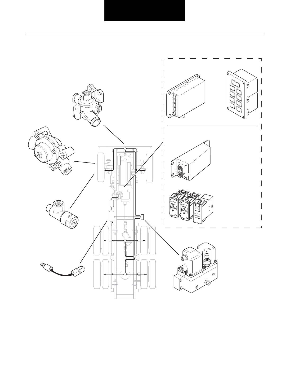
Driver Display
Module
Chassis Mount
ECU
Electronic Control Unit (ECU)
• With separate operator controls
– or –
• With integrated operator controls
Pneumatic Control Unit
Pressure Switch
Air Transport Valve
(optional)
Wheel Valve
Quick Release Valve
Central Tire Inflation System Components
3
Page 7
CTIS Components
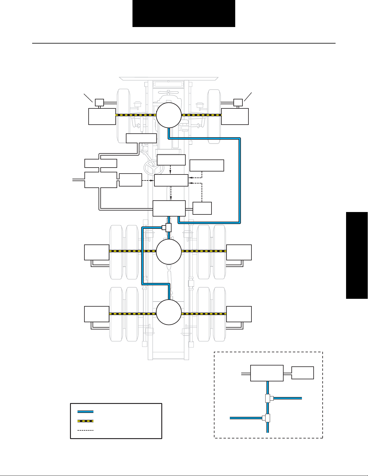
Simplified System Schematic
Tire
Hose
Tire
Hose
To Steers
Pressure
Sensor
To D rive Axle 2
To D rive Axle 1
Load Sensor
(Optional)
Electronic
Control Unit
Pressure
Switch
To P rimary and
Secondary
Tanks
Single Channel System
System Key
Pneumatic – Upper Control Lines
Electrical
Wheel
Valve
Wheel
Valve
Compressor
Speed Sensor
Air Transport
Valve (Optional)
Air Transport
Valve (Optional)
Tire
Hose
Supply Tank
Air Dryer
Tire
Hose
Tire
Hose
Tire
Hose
Supply Line
PCU
Sensor
Supply Line
Pneumatic – Lower Control Lines
Pneumatic
Control Unit
Quick
Release
Valve
Quick
Release
Valve
Wheel
Valve
Wheel
Valve
Quick
Release
Valve
Wheel
Valve
Wheel
Valve
PCU
General Information
4
Page 8
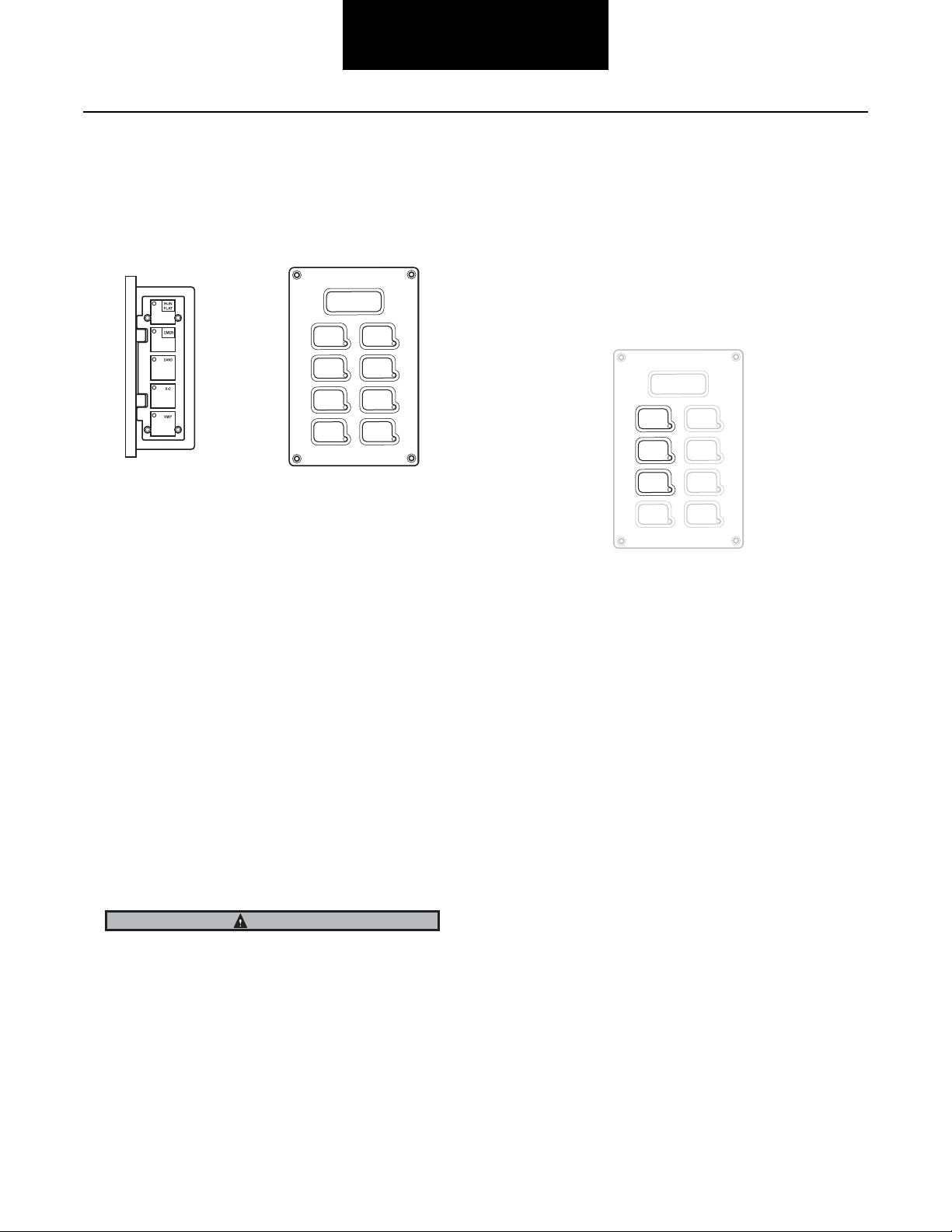
Flange or Panel—Operator Controls
RUN
FLAT
EMER
EMPTY
MUD
SAND
SNOW
PARTIAL
LOAD
CROSS
COUNTRY
FULL
LOAD
H GHWAY
OVER SPEED
CHECK TIRES
WARNING
RUN
FLAT
EMER
MUD
SAND
SNOW
CROSS
COUNTRY
HIGHWAY
OVER SPEED
CHECK TIRES
EMPTY
PART AL
LOAD
FULL
LOAD
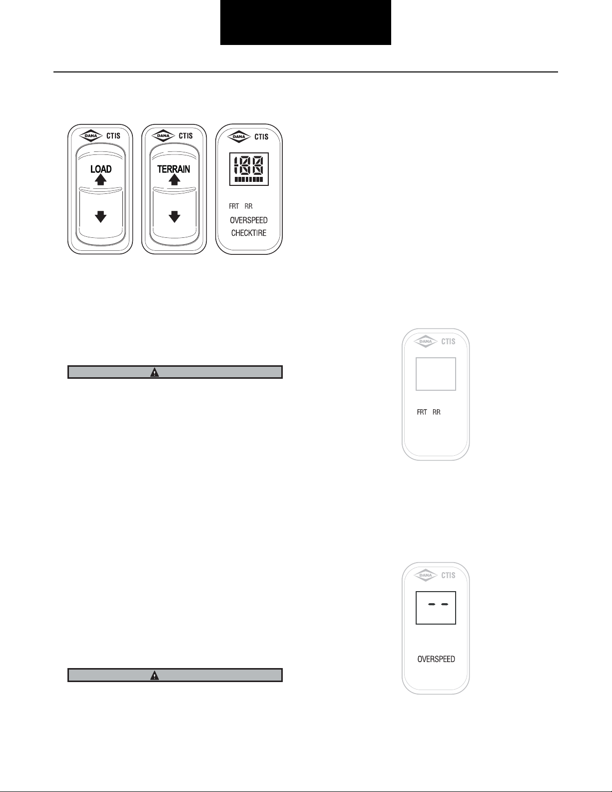
Operator Instructions
The integrated push button/display is the primary interface for
display of system information and for push button entry of
system instructions. The following sections explain the
purpose and operation of the ECU controls and display.
Terrain Selection
These keys select pressures appropriate for different surface
conditions. Any mode may be selected at any time (within
built in speed limitations). Depressing the button for the
current mode will result in a pressure check.
HWY (Highway)—For operation on improved paved surfaces.
Load Selection (Optional)
This feature allows selection of pressures appropriate for
different vehicle load conditions (full load, partial-load,
empty). Switching the load setting will result in a pressure
check and subsequent changing of the pressures as
determined by the system.
Mode Annunciator Lights
The associated annunciator lights indicate the selected mode
and signal one of two states:
XC (Cross Country)—For operation on non-paved secondary
roads.
SAND (Sand)—For operation on trails and other unimproved
surfaces.
EMER (Emergency)—For selection of extremely low tire
pressures to help free a stuck vehicle, or to traverse a short
distance over a terrain known to require very low tire
pressures. Since this is an extremely low pressure, the
warning lamp will flash whenever this pressure is utilized.
The EMER key is for extreme conditions only and should not
be used for normal driving.
5
If the light is flashing:
The system is in the process of checking or changing pressures to attain the pressure(s) associated with that mode
light.
Some clicking may be heard from the PCU as the system
cycles to achieve the new pressure(s). A deflate will be
periodically interrupted as the system checks tire pressures to
determine how much further deflation is necessary.
Note: Adequate supply system pressure is required to begin
or continue any pressure changing sequence.
If the light is on steady:
The selected pressure has been achieved, the tires have been
isolated and the system is depressurized. The system will
cycle periodically to assure that tire pressure is maintained.
Note: The system is designed to allow tire pressure increase
due to heat buildup during vehicle use. This system will
not automatically deflate these pressure buildups—a
lower pressure mode must be selected to initiate a
deflate.
Page 9
Operator Instructions
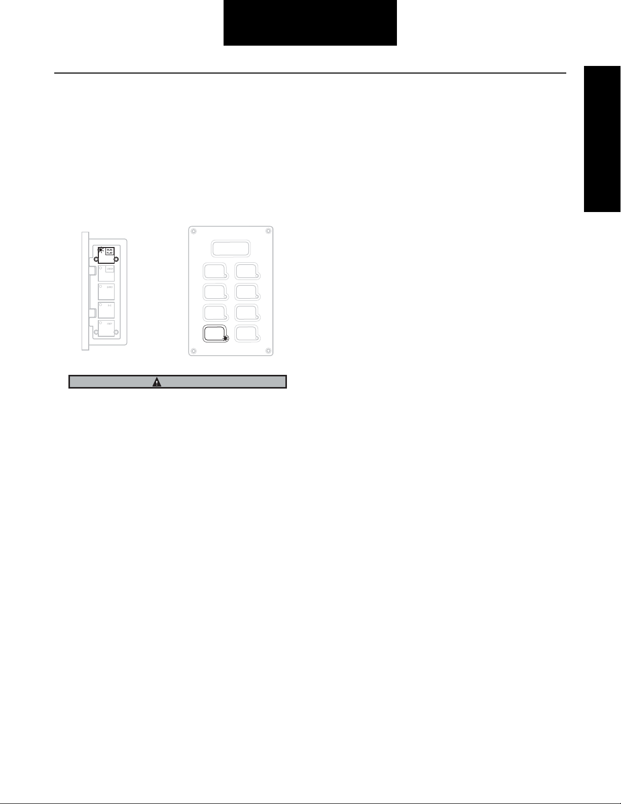
Flange or Panel
EMER
EMPTY
MUD
SAND
SNOW
PART AL
LOAD
CROSS
COUNTRY
FULL
LOAD
H GHWAY
OVER SPEED
CHECK TIRES
RUN
FLAT
CAUTION
Run Flat Key and Annunciator Light
This key instructs the system to check tire pressures at more
frequent intervals. This key also allows the operator to
override the “4 flashing lights” (tire leak imbalance) codes and
reattempt 2 lights and some 5 lights codes. (See Warning
Signals in next section). While the system is in RUN FLAT
mode, the RUN FLAT light will flash on and off. The “RUN
FLAT” feature will automatically deselect after 10 minutes, or
may be shut off by pressing the button a second time.
Selecting RUN FLAT to enable the system to inflate a significantly low tire may cause other tires on that channel to
temporarily lose pressure. This condition will be corrected
once the low tires is inflated to the pressure of the other
tires.
6
Page 10
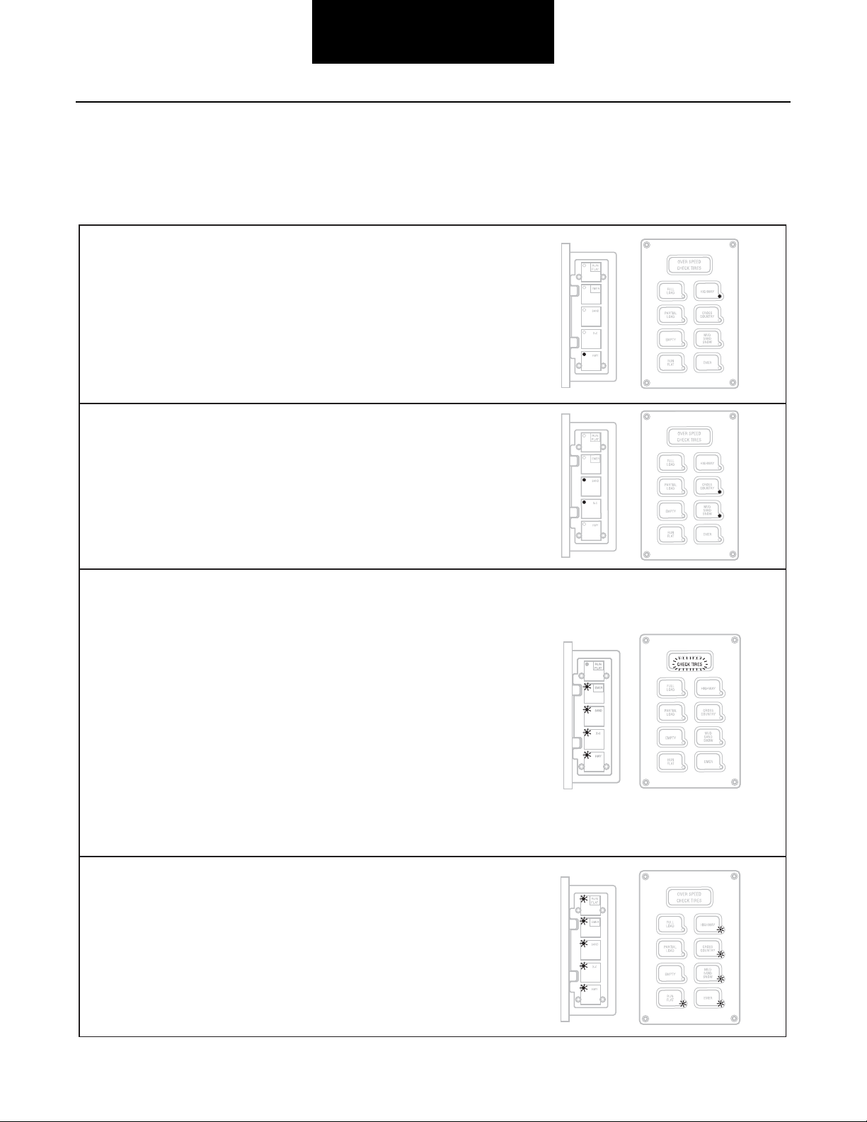
Operator Instructions
Single Terrain Light
• Flashing - System is working to achieve new pressures
associated with that mode light.
• Solid - Pressure is achieved, system is not active, and wheel
valves are closed.
2 Terrain Lights on Solid
System has shut off, closing wheel valves, with tire pressure
between two mode settings.
• Infl ating or defl ating tires is taking too long.
• CTIS is still operational.
• Select any mode button to re-attempt pressure change.
• On 2-channel systems, normal operation continues on
unaffected channel.
• Frequent occurrences may indicate need for service.
4 Terrain Lights Flashing or CHECK TIRES Flashing
Indicates low pressure in one or more tires. Stop vehicle and
identify damage.
• System shuts off, closing wheel valves, and waits for
operator instruction.
• T
ire damage i
s possible.
• CTIS should not be operated if major tire damage is found.
Repair tire before continuing to operate vehicle.
• On 2-channel systems, normal operation will continue on
the unaffected channel.
• If tire damage is minimal, operate CTIS by selecting RUN
FLAT.
Not
e: Repeated use of RUN FLAT to override mode light warnings
may result in tires infl ating higher than set point.
Note: Excessive air seal leakage on cold weather startup may
result in "4-5 Mode Lights" warning. If no tire damage exists, this
condition will self-correct as seals warm up with use.
5 Lights Flashing
System shuts off at least one channel due to fault detection on a
CTIS component.
• System closes wheel valves.
• System may periodically cycle PCU to determine if fault still
exists.
• On 2-channel systems, operation may be allowed on the
unaffected channel.
• Get service at next opportunity.
• No ability to override
system.
Several warning signals report operating problems. The Central Tire Infl ation System uses general sequences displayed
on the electronic control unit lights and an instrument panel-mounted warning lamp to identify the type and area of fault.
Flange or Panel—Warning Signals
7
Page 11
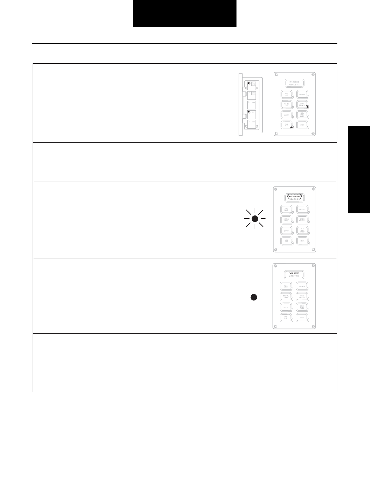
Flange or Panel
RUN FLAT Flashing (with a Terrain Light)
RUN FLAT is selected, and tire pressures are checked at more
frequent intervals.
• If RUN FLAT is pushed to clear a "4 Mode Lights" fl ashing
display, imbalance and confi rmation fault detection is
overridden for the duration of RUN FLAT.
• Turn off by depressing RUN FLAT again or it will "time-out"
after 10 minutes.
Warning: RUN FLAT sho
uld not be used to infl ate tires with
substantial damage/defects. Use of RUN FLAT can result in other
tires on channel losing pressure.
No Terrain Lights
CTIS senses either a low system voltage or an electrical fault with a
Pneumatic Control Unit solenoid.
• System shuts off, closing wheel valves.
• Vehicle power i
s inadequate.
Flashing Warning Lamp and/or Buzzer or OVER SPEED Flashing
Vehicle speed is too fast for pressure selected.
• Reduce speed or select higher pressure by pressing
appropriate key.
• Continued operation in this mode will result in automatic
selection of more appropriate pressure setting.
• Warni
ng lamp may fl ash while system is in EMERGENCY
mode.
Solid Warning Lamp or Solid OVER SPEED
ECU has seen 25-50 ignition cycles without seeing any speed
signal.
• If no problem exists with speed circuit wiring or sensor,
lamp will go off when vehicle is moved.
Lights Sequentially Flashing (one after another)
A confi g uration error has occurred and the CTIS memory has been
"reloaded" from the system defaults.
• System reloads default confi g uration values.
• Pressing HWY and RUN FLAT butto
ns together may clear
display.
• Any past changes of target pressure, etc. should be
updated.
Lamp on
Instrument
Panel
Lamp on
Instrument
Panel
Operator Instructions
8
Page 12
Operator Instructions
CAUTION
CAUTION
Driver Display Module—Operator Controls
Display
The Driver Display Module (DDM) uses a multi-function display to indicate the current selections. The display will show
HY for highway pressures, CC for cross-country pressures,
SS for mud-sand-snow pressures, and E for emergency pressures.
Note: The system is designed to allow tire pressure increase
due to heat buildup during vehicle use. It will not automatically deflate these pressure buildups.
Channel Indicators
Load Selection
Vehicle load selection is represented by a horizontal bar graph
under the mode display. Depress the load rocker switch to
change the selection, up for increasing load and down for
decreasing load.
Operating a loaded vehicle at unloaded tire pressures may
result in tire overheating and reduced tire life or blowout.
Terrain Selection
The terrain selection is changed by depressing the terrain
rocker switch, up to increase pressures and down to decrease
pressures. Any switch operation which does not change pressures will command the system to do a pressure check.
Tire pressures for the following terrains can be programmed
and may be selected by the operator:
• (HY) Highway - For travel on paved surfaces at
higher speeds.
The DDM indicates FRT or RR, respectively, for front or rear
axle groups. A flashing indicator identifies a group which is
changing or checking pressures. A solid indicator identifies a
group that has achieved target pressure.
Service Code Indication
The DDM will not display service codes directly but will display two dashes if service is required. (Accessing the service
codes requires a diagnostic tool). Also, a solid over speed
indicator identifies a loss of expected vehicle speed input.
• (CC) Cross Country - For reduced speed operation
on secondary roads.
• (SS) Mud Sand Snow - For reduced speed operation
on unpaved surfaces.
• (E) Emergency - For selection of extremely low tire
pressures to help free a stuck vehicle.
The Emergency selection is for extreme conditions only and
should not be used for normal driving.
9
Page 13
Operator Instructions
Driver Display Module
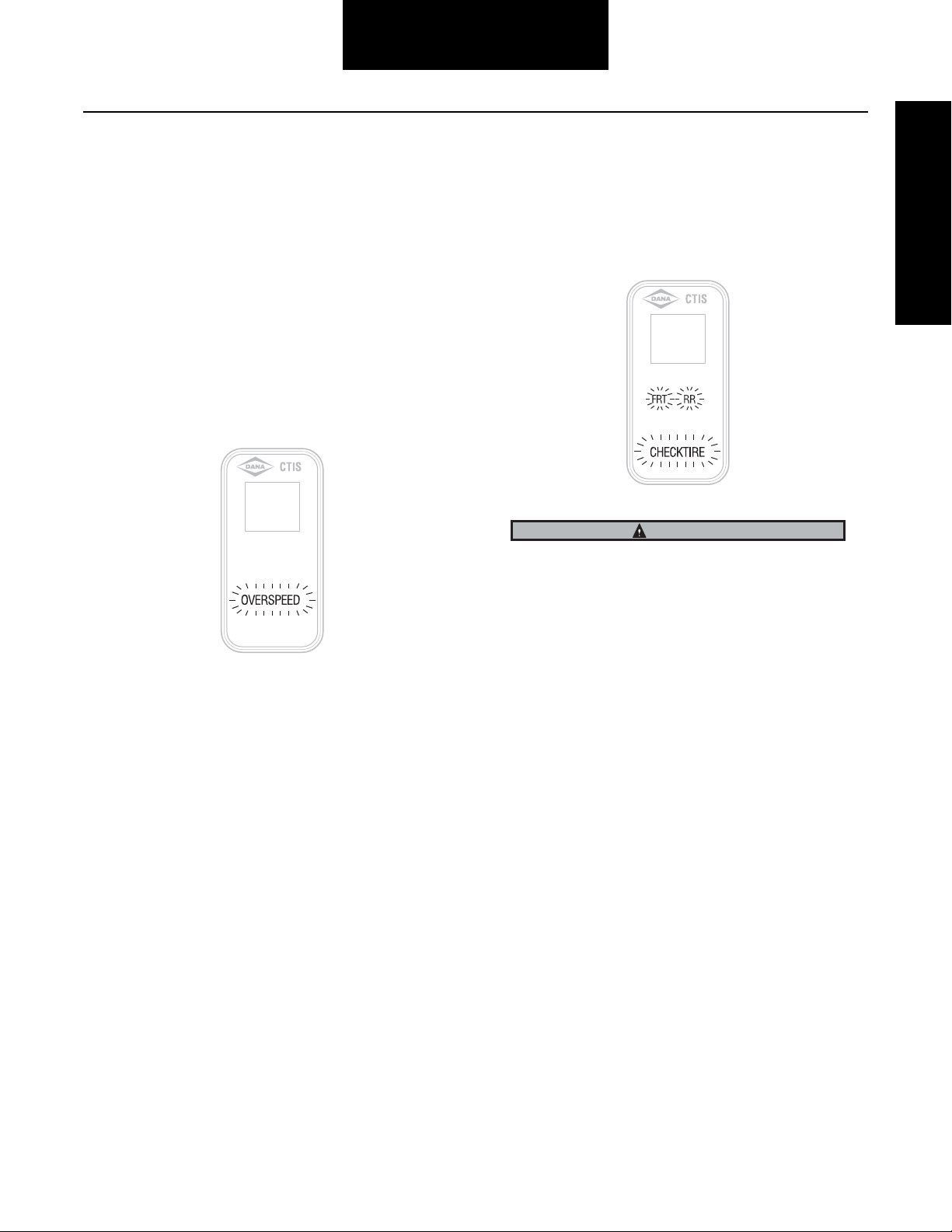
Driver Display Module (DDM)—Warning
Signals
CTIS includes two distinct warnings to report possible tire
problems and inappropriate vehicle operation. You must take
immediate action to either reduce vehicle speed or check tire
condition whenever these warnings are displayed.
Over Speed Flashing
This signal reports that the vehicle speed is too fast for the
pressure selected. You must either reduce speed or select a
higher pressure by pressing the appropriate key. Continued
operation in this mode will result in the system automatically
selecting a more appropriate pressure setting.
Check Tire Flashing
This signal reports that one or more tires may be at a significantly lower pressure than the others and could indicate that a
tire is not holding pressure. Blinking channel indicators (FRT
or RR) indicate the fault location. Stop the vehicle immediately in a safe place and identify the extent of tire damage.
IMPORTANT
Tires can still go flat! Although the Central Tire Inflation System is designed to identify under-inflated tires and fill these
tires to the desired operating pressure, you can still expect
that tires will occasionally be punctured or otherwise damaged during normal use and no longer retain air reliably. A
daily walk-around inspection of the vehicle at the start of the
day, including a manual check of the tires, is still an important
responsibility of the vehicle operator. Tire damage is more
apparent after the vehicle has been idle overnight and will be
more difficult to detect visually once the CTIS equipped vehicle is in operation. Although observation of excessive inflation
periods through the driver interface can help identify a tire
problem, you should have damaged tires replaced prior to
placing the vehicle in operation.
10
Page 14

Diagnostics
Diagnostics
This section covers the equipment and procedures used to
find and correct CTIS problems.
Test Equipment
CTIS troubleshooting can be performed at three levels:
1. PC diagnostics.
2. Handheld tester.
3. ECU warning signals (flashing light combinations).
Regardless of the testing equipment used, the
troubleshooting procedures will be based upon the diagnostic
service codes. Diagnostic tools offer the advantages of
computer-aided testing without interpreting service codes.
CTIS Diagnostics
The onboard system diagnostics are an important feature of
Spicer's CTIS. This section describes the use of service codes
to identify CTIS operating problems.
The CTIS uses a code to identify service issues. The codes
can be extracted from the ECU memory using a diagnostic
service tool equipped with the appropriate software. Refer to
the Service Codes Summary for more detailed information on
service codes.
Service Codes
Test Modes
Diagnostic tools allow the system to be placed in several
diagnostic modes:
Info—Display ECU information and configuration.
Codes—Active and historic codes are listed as reported by
the ECU.
Monitor (Normal)—CTIS operates normally, while status of
system components is observed.
Test—The following operations can be performed on each
channel (axle group):
• Check & Hold—System checks and
displays the pressures, then holds pressure in air
lines (quick test of control line and seal integrity).
• Deflate—System "manually" deflates (test the
deflation signal).
flate—System "manually" inflates (test for large
• In
leaks).
• Hold—Pressure is held in control lines (test for
small leaks).
Setup—Allows the technician to modify parameters such as
target tire pressures, etc.
Codes are described in the Service Codes Summary section.
Some service codes identify the component that is associated
with the problem. A list of possible causes is shown in order
of most likely occurrence.
In addition, the system stores service codes in the memory of
the ECU. These historical codes can only be accessed by a
diagnostic tool. Historical codes are automatically cleared
after 50 ECU resets with no active faults.
11
Page 15
Diagnostics
Download free Dana Diagnostic
T
Note:
Windows 98 or newe
Connect to diagnostic
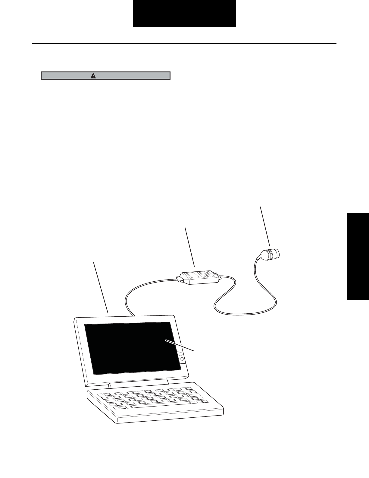
PC Diagnostics
CAUTION
A battery charger is not an adequate source of power.
Visit www.dana.com for free download of Dana Diagnostic
Tool (DDT).
PC diagnostics are easy to use and provide the quickest
diagnostic capabilities.
• Retrieve historical data, faults and tire pressures.
• Pressurize system to detect leaks.
• Access troubleshooting flowcharts and service
procedures.
Attach computer to RP1210A
communications box.
To use this program, an RP1210A compatible interface box
and cables are needed to connect the PC to the vehicle.
For these types of interface boxes to work with the Dana
Diagnostic Tool program, you must install a "RP1210 driver"
program provided by the manufacturer of the interface box.
If you do not have this program, it can normally be obtained
from the manufacturer's web site. Please contact the
manufacturer of your interface box if you have any questions
regarding this process.
connector.
ool from dana.com.
Program requires
r.
Diagnostics
Follow on-screen
instructions.
12
Page 16
Diagnostics
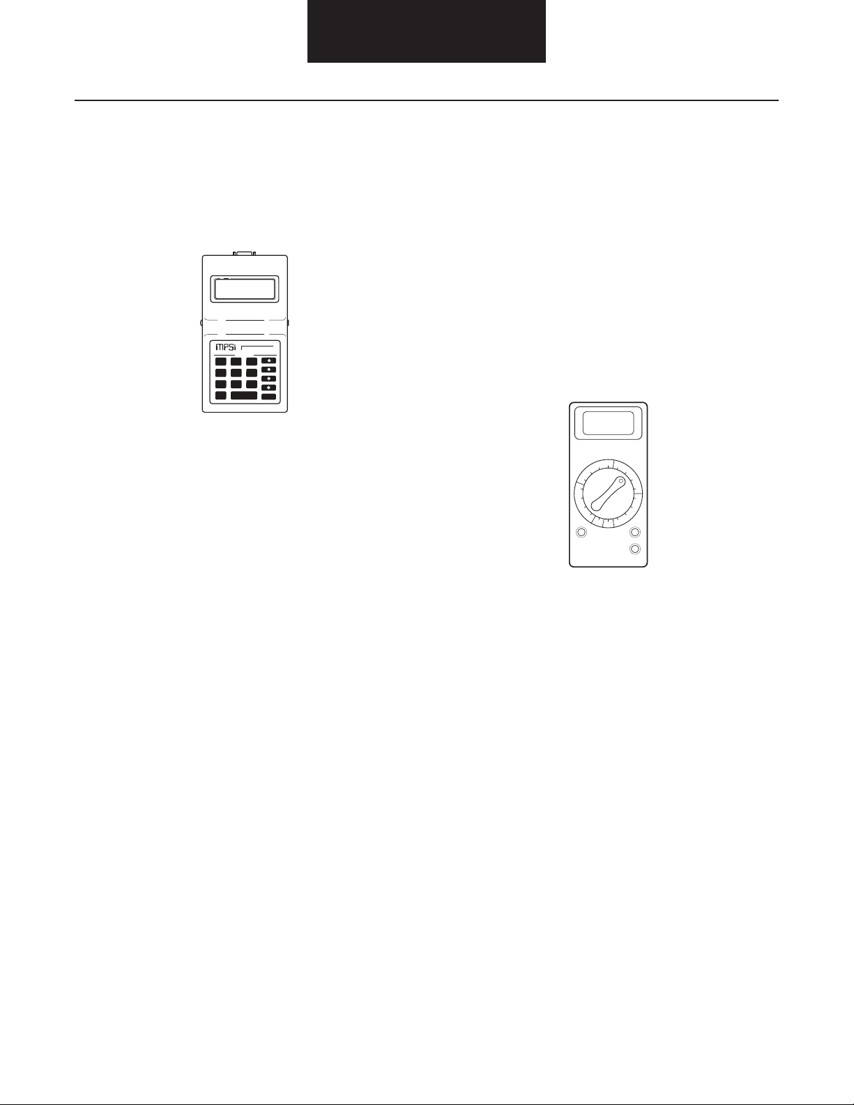
Handheld Tester
A Prolink handheld tester may be used to read and clear
service codes and to obtain a short description of failures. The
tester can initiate test sequences for controller outputs and
can also read system parameters when equipped with the
Dana program card.
KEN MOORE
M RO P O E SOR Y T MS NC
Pro-Link
9
7 8
6
4 5
2 3
1
ENTER
0
FUNC
Multimeter
Based upon system schematics and aided by component
specific service codes, a multimeter can be used to check
sensor and solenoid resistances and to find wiring harness
faults. The multimeter can be used to check the Tire Pressure
Control System wiring and components for:
• Continuity
• Ground
• Broken wires
• Open circuits
• Shorted circuits
• Incorrect battery voltage
13
Page 17
Service Codes Summary
Service Codes Summary
Diagnostics
The following chart provides a brief overview of the Central
Tire Inflation System (CTIS) service codes and the effect on
the system.
5 Flashing LIGHTs or
DDM – Dashes "--"
Low Pressure 26, 27 CHANNEL PRESSURE LOSS (Channel only checks pressures): Pressure check of
Low Air Supply 32 PRESSURE SWITCH REMAINS OPEN (System non-operative until switch closes):
Code No. Causes (numbered in order of likely occurrence)
given channel returns low reading (< 5 psig) indicating an extreme loss of pressure.
Repair and request pressure check to clear (press any mode button or run flat).
1) Open or broken line between PCU and wheel valve
2) Significant hub air seal leakage
3) Kinked or plugged line between supply tank and PCU
4) Faulty PCU sensor (ex. frozen water contamination)
5) PCU failure (supply off or control off)
6) Pressure switch failure (shorted closed)
For 4 minutes at vehicle speed > 20 mph pressure switch failed to close.
Repair and allow pressure switch to close to clear.
1) Compressor governor cutout set too low
2) Pressure switch unplugged, or open wire
3) Faulty pressure switch (failed open)
4) Faulty compressor
5) Broken, kinked, or plugged line from compressor to supply tank
Note: Any reference to a “channel” on a single-channel
system refers to all control lines and wheel ends.
Atmospheric 35 OUT OF RANGE ATMOSPHERIC READING (System waits to check pressures):
Atmospheric pressure check indicates vented PCU pressure is outside of valid
atmospheric range (5-20 psia).
Repair and request pressure check to clear (press any mode button or run flat).
1) Poor ground connection to PCU sensor
2) Faulty PCU sensor (ex, frozen water contamination)
3) Faulty PCU or blocked PCU exhaust vent
Inflate Trend 36, 37 INFLATE PRESSURE LOSS (System disables given channel): Given channel loses > 6
psi while inflating.
Repair and cycle ignition to clear.
1) Damaged tire or tire leakage
2) Leaking lines or seals
3) Faulty PCU (control solenoid off or additional channel stuck on)
Deflate Trend 14 FAILURE TO DEFLATE PROPERLY (System disables deflates): System gains >10 psi
pressure while attempting to deflate, or does not lower tires by even a small amount
of the intended change.
Repair and cycle ignition to clear.
1) Plugged or restricted PCU vent line
2) Faulty PCU relief valve
3) Poor ground connection to PCU sensor
4) Contaminated PCU
5) Faulty PCU
14
Page 18
Service Codes Summary (continued)
Diagnostics
5 Flashing LIGHTs or
DDM – Dashes "--"
PCU Sensor 33, 34 NO PCU SENSOR READING (System non-operative): No sensor voltage to ECU.
Pressure Switch 31 PRESSURE SWITCH SHORTED or FAILED CLOSED (System waits to check pres-
Code No. Causes (numbered in order of likely occurrence)
Clears 5 seconds following a valid reading.
1) Sensor is electrically disconnected
2) Pressure signal wire (XDCR SIGNAL) is shorted to ground, or open
3) PCU sensor VREF wire is shorted to ground, or open
4) Faulty sensor
PCU SENSOR READING TOO HIGH (System non-operative): Sensor voltage higher
than allowed.
Clears 5 seconds following a valid reading.
1) Pressure signal wire (XDCR SIGNAL) is shorted to power or XDCR VREF
2) Faulty sensor
sures): Pressure switch is read as closed, but pressure check of supply tank
indicates insufficient air pressure to continue.
Repair and request pressure check to clear (press any mode button or RUN FLAT).
1) Wire to pressure switch shorted to ground
2) Faulty pressure switch (failed closed)
3) Faulty PCU (leaks air during supply tank check)
5 Flashing LIGHTs and
CHECK TIRES Solid
Inflate Trend 36, 37 INFLATE PRESSURE LOSS (System disables given channel): Given channel loses > 6
Code No. Causes (numbered in order of likely occurrence)
psi while inflating.
Repair and cycle ignition to clear.
1) Damaged tire or tire leakage
2) Leaking lines or seals
3) Faulty PCU (control solenoid off or additional channel stuck on)
15
Page 19
Service Codes Summary
Service Codes Summary (continued)
Diagnostics
4 Flashing LIGHTs or
CHECK TIRES Flashing
Tire Leak (Imbalance) 44, 45 TIRES IMBALANCED (System only checks pressures on given channel): Pressure
Tire Leak (Confirm) 41, 42 CONFIRMATION FAILURE (System disables given channel): Given channel fails to
2 Terrain Lights on
Solid or DDM –
Dashes "--"
Code No. Causes (numbered in order of likely occurrence)
check indicates a tire on the given channel may be significantly lower than other tires
on same channel. RUN FLAT will override this fault.
1) Significant tire pressure loss (i.e. overnight leakdown)
2) Significant tire damage or leaks
3) Leaking lines or seals
4) Contaminated wheel valve filters
5) Restricted tire valve stem
6) Faulty wheel valve (leaking back through QRV)
7) Kinked or restricted control lines
confirm 10 times in a row.
RUN FLAT will override this fault.
1) Damaged tire or tire leakage
2) Leaking hose between wheel valve and tire
3) Faulty wheel valve (leaking back through QRV)
4) Restricted air passage between QRV and wheel valve
Code No. Causes (numbered in order of likely occurrence)
Between Modes 23, 24 SLOW INFLATE (Channel only checks pressures): Given channel takes too long(> 40
minutes) in active inflate (pressure switch closed) to achieve requested mode.
Repair and request pressure check to clear (any mode button or run flat).
1) Insufficient air supply
2) Contaminated wheel valve filters
3) Kinked, plugged, or leaking lines
SLOW DEFLATE (Channel only checks pressures): Given channel takes too long in
active deflate (> 20 minutes) to achieve requested mode.
Repair and request pressure check to clear (any mode button or run flat).
1) Contaminated wheel valve filters
2) Restricted tire valve stem
3) Leaking upper control lines
4) Faulty PCU relief valve
5) Restricted QRV exhaust
6) Restricted PCU vent line
16
Page 20
Service Codes Summary (continued)
Diagnostics
2 Terrain Lights on
Solid or DDM –
Dashes "--"
Deflate Signal 11, 12, 16 INCORRECT DEFLATE PRESSURE: Deflate signal reads outside of configured range
No Terrain Lights or
DDM – Dashes "--"
PCU Solenoid 51, 52, 54,
Code No. Causes (numbered in order of likely occurrence)
for 30 seconds. If occurs during multi-channel deflate, system will reattempt deflates
on individual channels.
Repair and request pressure check to clear. (any mode button or run flat).
1) Faulty PCU relief valve
2) Leaking upper control lines
3) PCU internal leaks
4) Deflate solenoid poppet stuck in non-energized position
5) Poor ground connection to PCU sensor or faulty sensor
Code No. Causes (numbered in order of likely occurrence)
ELECTRICAL SOLENOID FAILURE (System non-operative): Solenoid fails electrical
55, 56
diagnostics for approximately 2 seconds.
Repair & cycle ignition to clear.
1) Solenoid or harness wire is shorted to ground
2) Solenoid or harness wire is shorted to power
3) Faulty solenoid
No Terrain Lights or
DDM – Blank Display
Power 17 POWER (System non-operative): After initialization, voltage drops below 18V for > 15
DDM – Dashes "--" Code No. Causes (numbered in order of likely occurrence)
Display Control
Communications
Code No. Causes (numbered in order of likely occurrence)
seconds.
Clears immediately when voltage > = 18V.
1) Low battery voltage
2) Poor ground connection to ECU
3) Poor power connection to ECU
75 NO COMMUNICATION TO DDM: ECU not receiving data from DDM user interface.
Repair to clear.
1) No data link connection to DDM (damaged harness wiring)
2) Faulty DDM
17
Page 21
Service Codes Summary
Service Codes Summary (continued)
Diagnostics
Lights Sequentially
Flashing
Configuration Error N/A CONFIGURATION ERROR (System is “Limp-Home”): System has reloaded the system
Solid Warning Lamp
or Solid OVER SPEED
Speed Signal 18 NO SPEED SIGNAL (System operation is normal): ECU has been reset 25-50 times
Code No. Causes (numbered in order of likely occurrence)
defaults, eliminating any changes (target pressures, etc.) previously programmed via
a diagnostic tool. Pressing HWY and RUN FLAT at the same time may clear the
display...updated config data should be reprogrammed.
1) Configuration connector loose or missing
2) Faulty ECU (if repeatedly occurs)
Code No. Causes (numbered in order of likely occurrence)
without any speed input to ECU. Note: Fault will be set immediately on power up.
Any speed input (driving vehicle with good speed sense operation) will clear fault.
1) Vehicle has been started approximately 25-50 times without being moved (no
speed input).
2) Sensor is electrically disconnected
3) Either speed sense wire is open or shorted to ground
4) Faulty speed sensor
5) Sensor actuation failure (Tang broken/disconnected on mechanical sensor, or
incorrect gap on pole sensor)
6) Both speed sense wires are shorted together
76, 77 Expected data link message not received
No Indication or DDM
– Dashes "--"
Miscellaneous Output 53, 57, 58,
No Indication Code No. Causes (numbered in order of likely occurrence)
Wheel Valve Shut Off 61, 62, 64, 65LOSS OF PRESSURE DURING SHUT OFF:
Code No. Causes (numbered in order of likely occurrence)
SPARE OUTPUT OR COMPONENT FAILURE:
67, 68
1) Harness wire is shorted to ground
2) Harness wire is shorted to power
3) Faulty component
1) Wheel valve shut off failure
2) Air passage restriction
18
Page 22

Diagnostics
Inaccurate Tire Pressures
May be caused by leaking control lines, clogged wheel valve
filters or valve stems, or closed Air Transport Valves.
Run Flat Definition
Pressing the RUN FLAT button once during normal system
operation puts the system in Run Flat Mode for 10 minutes
and causes several things to happen:
• The RUN FLAT light will flash along with the selected
mode light.
• A full pressure check (including atmospheric) is
requested.
• After 10 minutes Run Flat will automatically
deselect...OR... pushing RUN FLAT button again
will deselect it. It can be reselected by pressing the
button again after timeout.
• Tire pressures are checked at more frequent
intervals.
In addition, pressing the RUN FLAT button while the ECU is
displaying a “4 lights” flashing code will cause all “4 mode
lights” flashing codes (imbalance and confirmation) to be
overridden for the duration of RUN FLAT.
Note: ECU replacement—ECUs are NOT a typical cause of
problems. If an ECU is replaced, the system should be
carefully rechecked to make sure the problem has been
fixed, and does not reoccur.
19
Page 23

Diagnostics
Troubleshooting Tips
Troubleshooting Tips
This checklist outlines some general hints and guidelines that
will be helpful in tracking down and correcting operating
problems.
The ECU only displays one active code.
Only the most recent service code displays on the
ECU lights. In troubleshooting, be alert for related
codes. Use of a diagnostic tool offers the advantage of
spotting multiple active codes as well as retrieving
historical codes.
A cleared code alone does not indicate a corrected
problem.
A code is set by a specific fault condition and may be
cleared by switching the ignition off, and then on. It’s
possible to clear a code (i.e, clear the flashing lights)
only to have it display again when the fault condition
reoccurs. To ensure that a problem is fixed, you must
run the system through the same operating modes
that caused the problem and verify that the service
code does not reappear.
Electrical faults are often connection problems.
The most likely cause of electrical faults will be damaged wires or connections. As a first step in troubleshooting all electrical codes, switch off vehicle
ignition, then disconnect applicable connectors and
inspect for damage. (Switching off the ignition is
required before disconnecting the harness at the Electronic Control Unit, but is also a recommended practice before all other electrical system disconnections.)
Clean or repair all bad connections before proceeding.
Disconnect the Electronic Control Unit connector
with ignition off.
To avoid setting electrical fault codes, make sure that
the ignition is off before unplugging the wire harness
connection at the Electronic Control Unit module.
Reconnect the connector before switching on the ignition.
System is not continually pressurized.
When troubleshooting pneumatic faults, keep in mind
that the air system is only pressurized as needed (for
example, in the inflate mode). This means that such
procedures as checking for leaks require the system
to be in an active pressurized state. This can be
accomplished most easily by using a diagnostic tool.
Basic vehicle air and power systems are not covered in this guide.
The Central Tire Inflation System requires air pressure
and electrical power supply from the base vehicle systems. Diagnosis and service of these systems is outside the scope of this manual.
2-Channel (front/rear) systems may respond differently than single-channel systems.
If a fault can be isolated to a specific channel, a 2channel system may allow continued operation on the
unaffected channel. When troubleshooting, use a
diagnostic tool to determine which channel has the
fault.
20
Page 24

Service Codes
5 Flashing Lights or DDM – Dashes "--" (Codes 26, 27)
Type: Low Pressure
System Mode Condition Possible Causes (listed in order of likely occurrence)
System waits to
check pressures
Faulty pneumatic system,
or extremely low pressure
reading
• Open line between PCU and wheel valve
• Significant hub air seal leakage
• Open solenoid (PCU electrically or pneumatically disconnected)
• Crimped or plugged line between supply tank and PCU
• Faulty PCU sensor (ex. frozen water contamination)
• PCU failure, supply or control off
• Pressure switch failure, shorted closed
• Faulty ECU
Air Pressure Check
Note that the Central Tire Inflation System is not continuously
pressurized; pressure checks occur on a periodic basis. During tire pressure checks, the system delivers compressed air
to each channel for approximately two seconds while monitoring the pressure in that channel.
Code Description
A “Low Pressure” code indicates an extreme low pressure
reading. The most likely cause is an open line which would
have a clearly audible leak during a pressure check. A secondary cause could be a faulty air delivery system (i.e. Pneumatic
Control Unit [PCU]Low Pressure (Codes 26, 27) electrically or
pneumatically disconnected).
Other components that can cause a Low Pressure code are:
• Electrically or pneumatically disconnected PCU
• Faulty PCU
• Restricted line between the supply tank and PCU
21
• Faulty PCU sensor
• Open line from PCU to Quick Release Valve
• Open line from Quick Release Valve to Wheel Valve
To correctly diagnose the faulty component, connect the Diagnostic Tool (see "Diagnostics" for test equipment and descriptions) and follow the procedure in the Low Pressure
troubleshooting tree.
See “Troubleshooting Tips” for general guidelines on system
diagnostics.
Page 25

Low Pressure (Codes 26,
27)
Low Pressure (Codes 26, 27)
On 2-channel systems, use the diagnostic
tool to identify the faulty channel: front or rear.
Using the diagnostic tool, initiate inflate mode
for the faulty channel.
Service Codes
Is there
extreme audible
pressure loss?
No
Verify that the pressure switch opens
when the supply tank is below 80 psi.
Note: Primary and secondary air brake
gauges do not reflect actual pressure in
the supply tank.
Does the
pressure switch
open?
No
Replace pressure switch and
recheck system.
Repair faulty components
Yes
Yes
and recheck system.
Is there a restricted
line between the supply
tank and PCU?
No
After a pressure
check, is the pressure
reading <5 psi?
No
Check harness and PCU for open supply or
control solenoids. See Solenoid Fault flowchart.
Replace PCU and recheck system.
Note: While replacing the PCU, pay particular
attention to possible air line contamination (e.g.,
oil, water, particles) which may suggest further
air system maintenance needs.
Yes
Make repairs to faulty
components and recheck
Yes
Replace PCU sensor
and recheck system.
system.
Does fault
reoccur?
Yes
Replace ECU and recheck system.
Note: ECUs are not a typical cause of problems. If
an ECU is replaced, the system should be carefully
rechecked to make sure the problem has been
fixed and does not reoccur.
No
Complete
22
Page 26

Service Codes
5 Flashing Lights or DDM – Dashes "--" (Code 32)
Type: Low Air Supply
System Mode Condition Possible Causes (listed in order of likely occurrence)
System waits to
check pressures
Pressure switch won’t
close
• Compressor governor cutout set too low
• Air dryer needs service
• Pressure switch unplugged
• Faulty pressure switch
• Faulty compressor
• Open or broken line from supply tank to PCU
• Crimped or plugged line from supply tank to PCU
Air Pressure Check
Note that the Central Tire Inflation System is not continuously
pressurized; pressure checks occur on a periodic basis.
During tire pressure checks, the system delivers compressed
air to the tires for approximately two seconds while
monitoring the pressure.
Code Description
A “Low Air Supply” code displays if system air pressure is
inadequate to perform a tire pressure check.
This occurs when the pressure switch will not close. The
components that can cause the pressure switch to remain
open include:
Pressure Switch Harness Connector
B
A
– or –
ECU Harness Connector
A
R
B
C
D
E
F
P
S
T
a
U
V
G
N
b
Z
c
Y
W
X
K
H
J
– or –
M
L
ABCDE
ABCDE
ABCDE
A C
B
FGHJK
FGHJK
FGHJK
3
2
1
• Compressor governor cutout set too low
• Pressure switch unplugged
• Faulty pressure switch
• Faulty compressor
• Open or broken line from supply tank to Pneumatic
Control Unit (PCU)
• Crimped or plugged line from supply tank to PCU
To correctly diagnose the faulty component, connect the Diagnostic Tool (see "Diagnostics" for test equipment and descriptions) and follow the procedure in the Low Air Supply
troubleshooting tree.
See “Troubleshooting Tips” for general guidelines on system
diagnostics.
23
Page 27

Low Air Supply (Code 32)
Low Air Supply (Code 32)
When the
governor cuts out, is the
supply pressure greater than
value shown in table? (Use
calibrated pressure gauge
in tank.)
Reset governor cutout
pressure and retest system.
Is the pressure
switch plugged in?
Plug in pressure switch and
retest system.
Using the diagnostic tool, verify
pressure switch operation.
Does the
pressure switch
close above setting
shown in table?
Is
continuity
OK?
Repair harness
and retest.
Verify air system capacity by checking
supply tank pressure buildup time.
Does the
supply tank build
up pressure?
Service code is not active. Reverify
flowchart steps and wait for fault to reoccur.
Repair vehicle air supply
system and retest.
Replace pressure switch
and retest system.
No
Yes
Yes
Yes
No
No
Yes
Yes
No
No
Pressure Switch
Part Number
673345 (black)
676770 (blue)
Minimum Supply
Tank Pressure
120 psig
125 psig
Identify vehicle pressure switch:
Part #673345 (black)
Part #676770 (blue)
Switch off ignition.
Disconnect the ECU connector and
the pressure switch connector.
There are two wires used for the pressure switch (PS).
One is the signal wire. The other connects the pressure
switch to GROUND.
Verify continuity between:
PS Harness ECU Harness
Connector Pin Connector Pin
T (Round Connector)
PS signal or
(pin A or B) G3 (Rectangular Connector)
AND
ForNon-M939 Style Vehicle
PS GROUND Vehicle GROUND
(other pin A or B)
For M939 Style Vehicle
PS GROUND L (Round Connector)
(other pin A or B)
Start pressure build
up in supply tank.
Service Codes
24
Page 28

Service Codes
5 Flashing Lights or DDM – Dashes "--" (Code 35)
Type: Atmospheric
System Mode Condition Possible Causes (listed in order of likely occurrence)
System waits to
check pressures
PCU pressure out of range
when PCU is “vented”
• Frozen water or other contaminant in PCU sensor
• Plugged PCU vent
• Poor ground connection to PCU sensor
• Faulty PCU sensor
• Faulty PCU
Air Pressure Check
Note that the Central Tire Inflation System is not continuously
pressurized; pressure checks occur on a periodic basis.
During tire pressure checks, the system delivers compressed
air to the tires for approximately two seconds while
monitoring the pressure.
Code Description
An “Atmospheric” code is logged if the atmospheric pressure
reading is out of range. The atmospheric pressure reading can
be out of range as a result of a blocked or restricted Pneumatic Control Unit (PCU) or vent line, contaminated PCU sensor (i.e. frozen water), air bleeding back into the PCU or
because of a faulty PCU sensor.
The components that can cause this code to be set include:
PCU Sensor Harness Connector
AB
C
– or –
ECU Harness Connector
A
R
B
C
D
E
F
P
S
T
a
U
N
b
Z
V
c
Y
W
X
G
K
H
J
– or –
M
L
CAB
ABCDE
ABCDE
ABCDE
FGHJK
FGHJK
FGHJK
3
2
1
• Faulty or contaminated PCU sensor
• Faulty or contaminated PCU
• Faulty Electronic Control Unit (ECU)
To correctly diagnose the faulty component, connect the Diagnostic Tool (see "Diagnostics" for test equipment and descriptions) and follow the procedure in the Atmospheric
troubleshooting tree.
See “Troubleshooting Tips” for general guidelines on system
diagnostics.
25
Page 29

Atmospheric (Code 35)
Atmospheric (Code 35)
Service Codes
Disconnect ECU and
PCU sensor connectors.
Check for continuity between:
Using the diagnostic tool, read
the atmospheric pressure.
Is the reading
between 5 and 20
psia?
Yes
Service code is not active. Reverify flowchart steps and wait
for fault to reoccur.
Is any audible
No
air flowing through
the PCU?
Yes
Replace PCU and recheck system.
No
PCU Sensor Harness ECU Harness
A (round connector) J (round connector)
B (oval connector ) H3 (rectangular connector)
Disconnect harness from PCU sensor and plug new
PCU sensor onto harness (do not install new sensor
in PCU yet). Verify atmospheric reading.
or or
Is there
continuity?
Yes
Is the reading
within range?
Yes
No
niP rotcennoCniP rotcennoC
Inspect and repair faulty
harness or pins.
No
Complete
Note: While replacing the PCU, pay particular
attention to possible air line contamination (e.g.,
oil, water, particles) which may suggest further
air system maintenance needs.
Yes
Replace ECU and recheck system.
Note: ECUs are not a typical cause of problems. If
an ECU is replaced, the system should be carefully
rechecked to make sure the problem has been
Is the reading
within range?
No
fixed and does not reoccur.
Install new sensor in PCU.
Verify atmospheric reading.
No
Is the reading
within range?
Yes
Complete
26
Page 30

Service Codes
5 Flashing Lights or DDM – Dashes "--" or 5 Flashing Lights and Check Tires Solid (Codes 36, 37)
Type: Inflate Trend
System Mode Condition Possible Causes (listed in order of likely occurrence)
Channel
inoperative
Loss of channel pressure in
inflate mode
• Damaged or leaking tire
• Leaking lines
• Leaking seals
• Leaking QRV
• Leaking wheel valve
• Faulty PCU
Code Description
An “Inflate Trend” code displays when tire pressure readings
are dropping while in inflate mode. Tire damage, which the
compressor cannot keep up with, may have occurred after
starting an inflate sequence. When possible, a 2-channel system will isolate this fault to a given channel.
The air leak can be located either before or after the wheel
valve location. The components located before the wheel
valve that may cause this include:
• Leaking control lines
• Leaking Quick Release Valve (QRV) exhaust port
• Leaking wheel air seals
Components located after the wheel valve that may cause this
include:
•Tire damage
• Rim leaks
• Leaking air lines
• Faulty wheel valve
To correctly diagnose the faulty component, connect the Diagnostic Tool (see "Diagnostics" for test equipment and descriptions) and follow the procedure in the Inflate Trend
troubleshooting tree.
See “Troubleshooting Tips” for general guidelines on system
diagnostics.
27
Page 31

Inflate Trend (Codes 36,
37)
Inflate Trend (Codes 36, 37)
On 2-channel systems, use the
diagnostic tool to identify the
faulty channel: front or rear.
Using the diagnostic tool, initiate
inflate mode on the faulty channel.
Is there a
damaged tire?
Is there a leaking
hose between a tire
and wheel valve?
Repair tire and retest system.
Replace the hose and
retest the system.
Make sure all tires on the channel
are at the same pressures.
Is air leaking
through the QRV?
Replace the QRV and
retest the system.
Are there any
leaks in the control
lines or seals?
Is air leaking
out the PCU vent
port?
Fault code is not active.
Reverify flowchart steps and
wait for fault to reoccur.
Repair leaks and retest.
Replace PCU and retest.
Note: While replacing the PCU, pay particular
attention to possible air line contamination (e.g.,
oil, water, particles) which may suggest further
air system maintenance needs.
Yes
No
No
Yes
No
Yes
Yes
No
Yes
No
Service Codes
28
Page 32

Service Codes
5 Flashing Lights or DDM – Dashes "--" (Code 14)
Type: Deflate Trend
System Mode Condition Possible Causes (listed in order of likely occurrence)
Inflate only Improper deflate sequence • Upper control line leak
• Plugged or restricted PCU vent line
• Faulty PCU relief valve
• Poor ground connection to PCU sensor
• Contaminated PCU
• Faulty PCU
Code Description
A “Deflate Trend” code displays when the system has determined that a deflate sequence is not functioning correctly.
This is the result of either a pressure increase during a deflation, or the system failing to lower the tires even a small
amount of the desired pressure drop.
29
Page 33

Deflate Trend (Code 14)
Deflate Trend (Code 14)
Yes
Using the diagnostic tool, manually
deflate the tires on one channel.
While
deflating, is the
system (relief valve)
pressure within 1 psig
of nominal? *
Continue using diagnostic tool
to deflate the tires to 45 psi.
Use manual pressure gauge
to verify all tires at 45 psi.
Use diagnostic tool to select
Check & Hold.
Pressure
reading < 55
psi?
2-channel
system?
Test should
be repeated for both
channels. Both channels
tested?
Are the tires
deflating?
Use diagnostic tool to
manually deflate the tires on
the other channel.
Fault is not active.
Reverify flowchart
steps and wait for fault
to reoccur.
Check wheel valve filters, replace as
necessary and recheck system.
Will the tires
deflate now?
Vent wheel valve covers
and recheck system.
Repair PCU restriction and
recheck system.
Is the PCU
vent line or relief
valve plugged or
restricted?
Use diagnostic tool to place system
into “pressure check and hold” mode.
Check for upper control line leaks.
Make repairs to faulty components.
Use diagnostic tool to
manually deflate the tires.
Replace PCU relief valve
and recheck system.
Perform continuity check on
front and rear channel
solenoids. See Solenoid
Fault flowchart.
Complete
Yes
Yes
Yes
Yes
No
No
No
No
No
No
Yes
Yes
No
2-channel
system?
Are the tires
deflating?
PCU is contaminated or faulty.
Clean, repair and/or replace
PCU as necessary and recheck
system.
Note: While replacing the PCU,
pay particular attention to
possible air line contamination
(e.g., oil, water, particles) which
may suggest further air system
maintenance needs.
PCU is contaminated or faulty.
Clean, repair and/or replace
PCU as necessary and recheck
system.
Note: While replacing the PCU,
pay particular attention to
possible air line contamination
(e.g., oil, water, particles) which
may suggest further air system
maintenance needs.
* Reference vehicle build
information for nominal
relief valve pressure.
While
deflating, is the
system (relief valve)
pressure within 1
psig of
nominal? *
No
No
No
Yes
Yes
Yes
Service Codes
30
Page 34

Service Codes
5 Flashing Lights or DDM – Dashes "--" (Codes 33, 34)
Type: PCU Sensor
System Mode Condition Possible Causes (listed in order of likely occurrence)
No operation No PCU sensor reading • Sensor electrically disconnected
• Pressure signal wire open
• Pressure signal wire shorted to ground
• PCU sensor VREF wire open
• PCU sensor VREF wire shorted to ground
• PCU sensor ground wire open
• Faulty sensor
• Faulty ECU
No operation High PCU sensor reading • Pressure signal wire shorted to VBAT or VREF
• Faulty sensor
• Faulty ECU
Code Description
A "Pneumatic Control Unit (PCU) Sensor" code occurs when
the Electronic Control Unit (ECU) receives an unusually high
or low reading from the PCU sensor. A diagnostic tool will
specify which of the two conditions is responsible for setting
the code.
Initial troubleshooting steps involve checking for a shortedto-ground or an open PCU sensor circuit.
If the circuits check out OK, secondary causes could involve a
faulty sensor or a faulty ECU.
See “Troubleshooting Tips” for general guidelines on system
diagnostics.
PCU Sensor Harness Connector
AB
C
– or –
ECU Harness Connector
A
R
B
C
D
E
F
P
S
T
a
U
N
b
Z
V
c
Y
W
X
G
K
H
J
– or –
M
L
CAB
ABCDE
ABCDE
ABCDE
FGHJK
FGHJK
FGHJK
3
2
1
31
Page 35

PCU Sensor (Codes 33, 34)
PCU Sensor (Codes 33, 34)
No
With ignition off, inspect socket
connections at ECU connector
and at PCU sensor 3-way.
Are connections
mechanically and
electrically sound?
Repair connection
as necessary.
Disconnect the ECU connector
and the PCU sensor connector.
Is there
continuity?
Check for short circuits between each
pair of PCU sensor harness pins:
A and B
B and C
C and A
A
Are any
shorted?
With ignition switch on, check
voltage between PCU sensor
harness pin B (round
connector) or pin A (oval
connector) and ground.
Is voltage
between 4.9 and
5.1 V?
Is the active
fault cleared?
Complete
Replace ECU and recheck system.
Note: ECUs are not a typical cause of problems. If
an ECU is replaced, the system should be carefully
rechecked to make sure the problem has been
fixed and does not reoccur.
A
Replace PCU sensor.
Inspect and repair
faulty harness.
Inspect and repair
faulty harness.
No
Yes
Yes
No
Yes
Yes
Yes
No
No
Check for continuity between the following points:
PCU Sensor Harness Connector Pin ECU Harness Connector Pin
c (round connector)
C (all connectors) or
H1 (rectangular connector)
B (round connector) b (round connector)
or or
A (oval connector) H2 (rectangular connector)
A (round connector) J (round connector)
or or
B (oval connector) H3 (rectangular connector)
Service Codes
32
Page 36

Service Codes
5 Flashing Lights or DDM – Dashes "--" (Code 31)
Type: Pressure Switch
System Mode Condition Possible Causes (listed in order of likely occurrence)
Pressure check
only
Pressure switch shorted or
won’t open.
• Pressure switch wire shorted to ground
• Faulty pressure switch (failed closed)
• Faulty PCU (leaks air during supply tank check)
Air Pressure Check
Note that the Central Tire Inflation System is not continuously
pressurized; pressure checks occur on a periodic basis.
During tire pressure checks, the system delivers compressed
air to each channel for approximately two seconds while
monitoring the pressure in that channel.
Code Description
A “Pressure Switch” code displays if system air pressure is
inadequate to perform a tire pressure check, yet the pressure
switch status is “closed”.
This occurs when the pressure switch will not open. The components that can cause the pressure switch to remain closed
include:
• Pressure switch wire shorted to ground.
• Faulty pressure switch (failed closed).
ECU Harness Connector
A
R
B
C
D
E
F
P
S
T
a
U
N
b
Z
V
c
Y
W
X
G
K
H
J
– or –
M
L
ABCDE
ABCDE
ABCDE
FGHJK
FGHJK
FGHJK
3
2
1
To correctly diagnose the faulty component, connect the Diagnostic Tool (see "Diagnostics" for test equipment and descriptions) and follow the procedure in the Pressure Switch
troubleshooting tree.
Note: This feature is only available on 2-channel systems.
This fault could be logged as a result of a singlechannel system (with a single-channel Pneumatic Control Unit [PCU]) being configured as a two-channel system. See “Configuration Error” troubleshooting tree to
verify correct harness configuration selection.
See “Troubleshooting Tips” for general guidelines on system
diagnostics.
33
Page 37

Pressure Switch (Code 31)
Pressure Switch (Code 31)
Service Codes
Identify vehicle pressure switch:
Part #673345 (black)
Part #676770 (blue)
Using the diagnostic tool,
verify pressure switch
status is closed.
Is the pressure
switch plugged in?
Yes
Using the diagnostic tool, verify
pressure switch operation.
Does the
pressure switch open
below psi value shown
in table?
Yes
No
No
Plug in pressure switch
and retest system.
Switch off ignition.
Disconnect the ECU connector
and the pressure switch connector.
Verify NO continuity between:
ECU Harness Connector Pins
T and F (round connector)
or
G3 and K2 (rectangular connector)
Part Number
673345 (black)
676770 (blue)
Pressure Switch
Open Value
78 psi
87 psi
Verify correct vehicle configuration.
See Configuration Error flowchart.
Use diagnostic tool to
read supply pressure.
Is supply pressure
Service code is not active. Reverify
flowchart steps and wait for fault to reoccur.
accurate?
Yes
No
Is there
continuity?
Yes
Repair harness and retest.
Replace PCU and recheck system.
Note: While replacing the PCU, pay
particular attention to possible air line
contamination (e.g., oil, water,
particles) which may suggest further
air system maintenance needs.
Replace pressure
No
switch and retest
system.
Does fault
reoccur?
Yes
Replace ECU and recheck system.
Note: ECUs are not a typical cause
of problems. If an ECU is replaced,
the system should be carefully
rechecked to make sure the problem
has been fixed and does not reoccur.
No
Complete
34
Page 38

Service Codes
4 Flashing Lights or CHECK TIRES Flashing (Codes 44, 45)
Type: Tire Leak (Imbalance)
Note: RUN FLAT overrides this fault.
System Mode Condition Possible Causes (listed in order of likely occurrence)
Channel only
checks pressures.
Tire pressure lower on one
tire than others.
• Minor tire leakage at startup (leaked overnight)
• Severe tire damage or leaks
• Contaminated wheel valve filters
• Restricted tires valve stem
• Leaking lines
• Leaking seals
• Leaking wheel valve
• Crimped or restricted control lines
Air Pressure Check
Note that the Central Tire Inflation System is not continuously
pressurized; pressure checks occur on a periodic basis.
During tire pressure checks, the system delivers compressed
air to each channel for approximately two seconds while
monitoring the pressure in that channel.
Code Description
An “Imbalance” code indicates that either the tire pressure on
one tire or wheel end was read lower than the other tires, or
there is an air leak someplace in the system.
Low tire pressure can be caused by a damaged tire, plugged
wheel valve filter or leaking air lines. An air leak can be located
either before or after the wheel valve.
Note: When using a diagnostic tool to inflate or inflate-hold a
channel with one low tire, air may be heard leaking out
or the Quick Release Valves (QRV) by the higher pressure tires. This is normal and should stop once the low
tire is inflated to the pressure of the other tires.
The components located before the wheel valve that may
cause a “Tire Leak (Imbalance)” code include:
• Leaking wheel air seals
• Leaking control lines
Components located after the wheel valve that may cause an
imbalance include:
• Damaged tire
• Rim leaks
• Clogged or restricted Wheel Valve filter or valve stem
• Leaking air lines
• Wheel valve damage
To correctly diagnose the faulty component, connect the Diagnostic Tool (see "Diagnostics" for test equipment and descriptions) and follow the procedure in the Tire Leak (Imbalance)
troubleshooting tree.
See “Troubleshooting Tips” for general guidelines on system
diagnostics.
• Restricted QRV exhaust port
35
Page 39

Tire Leak (Imbalance)
(Codes 44, 45)
Tire Leak (Imbalance) (Codes 44, 45)
On 2-channel systems, use diagnostic tool to
identify faulty channel: front or rear.
Manually check the tire pressures on the faulty
channel at the wheel valves.
Check for a blocked QRV exhaust or
plugged wheel valve filter or valve
stem. Make repairs to faulty
components and recheck the system.
Yes
Are any wheel
readings low?
No
Are any wheel
readings high?
Service Codes
Yes
Check the following:
Tire damage
Wheel valve filter
Air line leaks
Wheel seal air leaks
Wheel valve leaks
Repair faulty components
and recheck the system.
Make repairs to faulty
components and recheck system.
No
Use diagnostic tool to place system into
inflate mode and check for audible leaks
(see note under Code Description on
Yes
Use diagnostic tool to place system into
“Pressure Check and Hold” mode and look
previous page).
Is there an
audible leak?
No
for steady hold pressure.
Was pressure
steady?
Yes
Use diagnostic tool to
vent system.
Is air leaking
from the QRV
exhaust port.
Yes
Locate the leaking wheel valve
associated with that QRV and
replace it. Recheck the system.
Check the system for
kinked lines. Repair faulty
No
components and recheck
the system.
No
Find leak and make repairs to faulty
components. Recheck system.
36
Page 40

Service Codes
4 Flashing Lights or CHECK TIRES Flashing (Codes 41, 42)
Type: Tire Leak (Confirm)
Note: RUN FLAT overrides this fault.
System Mode Condition Possible Causes (listed in order of likely occurrence)
Channel inoperative
Channel confirmation failure • Damaged or leaking tire
• Leaking line between wheel valve and tire
• Plugged or restricted QRV
• Leaking wheel valve
• Plugged or restricted PCU vent line
• Restricted air passage between QRV and wheel valve
Air Pressure Check
Note that the Central Tire Inflation System is not continuously
pressurized; pressure checks occur on a periodic basis.
During tire pressure checks, the system delivers compressed
air to each channel for approximately two seconds while
monitoring the pressure in that channel.
Code Description
A “Tire Leak” occurs if a channel fails to confirm tire pressure.
Following an inflate or deflate sequence, the Central Tire
Inflation System will return to confirm, or “double-check” the
new pressure. If the pressure has dropped, the system will reinflate, and then reconfirm the tires. After multiple failed
confirmation attempts, the system will log a Tire Leak
(Confirm) code and the system will become inoperative.
A confirmation failure can be caused by:
• Damaged or leaking tire
• Leaking air line between the wheel valve and tire
• Plugged or restricted Quick Release Valve (QRV)
• Leaking wheel valve
37
• Plugged or restricted Pneumatic Control Unit (PCU)
vent line
• Restricted air passage between QRV and wheel valve
To correctly diagnose the faulty component, connect the Diagnostic Tool (see "Diagnostics" for test equipment and descriptions) and follow the procedure in the Tire Leak
(Confirm) troubleshooting tree.
See “Troubleshooting Tips” for general guidelines on system
diagnostics.
Page 41

Tire Leak (Confirm) (Codes
41, 42)
Tire Leak (Confirm) (Codes 41, 42)
No
Using the diagnostic
tool, initiate inflate mode.
Is there a
damaged tire?
Is there a leaking
hose between a tire
and wheel valve?
Repair tire and
retest system.
Replace the hose and
retest the system.
Use diagnostic tool to
vent system.
Does air
continue to vent
out PCU vent
line?
Is air leaking
through the QRV
exhaust?
Service code is not active.
reverify flowchart steps and
wait for fault to reoccur.
Check vent line.
Identify axle where
tire pressure is low.
Replace QRV.
Locate the leaking wheel valve
associated with that QRV and
replace it. Recheck the system.
On 2-channel systems, use the diagnostic tool
to identify the faulty channel: front or rear.
Manually check the tire pressures on the faulty
channel at the wheel valves. A low tire(s)
indicates likely location of problem.
Yes
Yes
Yes
No
No
Yes
No
Check for restrictions
between QRV and
wheel valve.
Are restrictions
present?
Yes
No
Repair restrictions and
recheck system.
Service Codes
38
Page 42

Service Codes
2 Terrain Lights on Solid or DDM – Dashes "--" (Codes 23, 24)
Type: Between Modes
System Mode Condition Possible Causes (listed in order of likely occurrence)
Pressure check
only
Pressure check
only
Slow inflate • Faulty compressor
• Restricted flow at wheel valve air filters
• Crimped or plugged lines
Slow deflate • Restricted flow at wheel valve air filters or valve stem
• Leaking upper control lines
• Plugged or restricted PCU vent port
• Restricted tire valve stem
• Faulty PCU relief valve
• Restricted QRV exhaust port
Code Description
A “Between Modes” occurs if a channel inflates or deflates too
slowly. The maximum allotted time for an inflate is 40 minutes, or 20 minutes for a deflate. The most likely cause for a
slow inflate is a faulty compressor or similar problem resulting in inadequate air supply to the Central Tire Inflation System. The most likely cause for a slow deflate is a leaking
upper control line, causing the deflate signal to be low.
If the system is able to generate a sufficient air supply, a
“Between Modes” code means that a leak or restriction exists
in an air passage. The components that may contain a
restricted or leaking air passage include:
To correctly diagnose the faulty component, connect the Diagnostic Tool (see "Diagnostics" for test equipment and descriptions) and follow the procedure in the Between Modes
troubleshooting tree.
See “Troubleshooting Tips” for general guidelines on system
diagnostics.
• Wheel valve air filters
• Quick Release Valve (QRV)
• Pneumatic Control Unit (PCU) vent port restriction
• Air supply lines
• Restricted tire valve stem
• Faulty PCU relief valve
• Restricted QRV exhaust
39
Page 43

Between Modes (Codes
23, 24)
Between Modes (Codes 23, 24)
Verify air system capacity by checking
air system pressure buildup time.
Does the air
supply system
build up?
No
Service Codes
Rebuild or replace
wheel valve.
Repair air supply system
and retest system.
No
Yes
On 2-channel systems, use the diagnostic tool
to identify the faulty channel: front or rear.
Using the diagnostic tool, initiate deflate mode.
Is one tire or axle
group deflating less
than the others?
No
Are all tires
deflating too
slowly?
No
Yes
Yes
On the tires or axles that deflate
slowly, check for:
Restricted QRV exhaust
Clogged wheel valve filters
Plugged tire valve stem
Yes
While
deflating, is the
system (relief valve)
pressure within 1 psig
of nominal? *
Complete
Did system
deflate normally?
No
Yes
Yes
Use diagnostic tool to place system
into “pressure check and hold”
mode.
Check for upper control line leaks.
Make repairs to faulty components.
Use diagnostic tool to
manually deflate the tires.
While
deflating, is the
system (relief valve) pressure
within 1 psig of
nominal? *
Complete
Initiate inflate mode and check
for crimped or restricted lines.
* Reference vehicle build
information for nominal
relief valve pressure.
Repair PCU restriction and
recheck system.
Yes
No
Is the PCU
vent line or relief
valve plugged or
restricted?
No
Replace PCU relief valve
and recheck system.
40
Page 44

Service Codes
2 Terrain Lights on Solid or DDM – Dashes "--" (Codes 11, 12, 16)
Type: Deflate Signal
System Mode Condition Possible Causes (listed in order of likely occurrence)
Inflate only Inadequate deflate signal in
the PCU and control lines
• Plugged or restricted PCU vent line
• Faulty PCU relief valve
• Faulty PCU
• Poor ground connector to PCU sensor
• Faulty PCU sensor
Code Description
A "Deflate Signal" indicates inadequate deflate signal in the
Pneumatic Control Unit (PCU) or failure to sustain the signal
in the control lines of a given channel.
When a deflate is requested, the system drops the control line
pressure to a preset level which is established by the PCU’s
relief valve. 2-channel systems may start separate channels at
different times.
If the proper pressure (vehicle specific, but typically a subset
of 6-22 psi) cannot be maintained by the PCU, either a Channel Deflate Loss or Loss of Deflate signal code is logged.
On 2-channel systems, if the relief valve pressure (deflate signal) cannot be maintained while both channels are deflating,
the system will attempt to deflate the channels individually
and will log “Deflate Signal” codes for an individual channel
with a problem.
PCU Sensor Harness Connector
AB
C
– or –
ECU Harness Connector
A
R
B
C
D
E
F
P
S
T
a
U
N
b
Z
V
c
Y
W
X
G
K
H
J
– or –
M
L
CAB
ABCDE
ABCDE
ABCDE
FGHJK
FGHJK
FGHJK
3
2
1
This can be caused by:
• Faulty PCU (relief valve)
• Plugged or restricted PCU vent line
• Line leak
To correctly diagnose the faulty component, connect the Diagnostic Tool (see "Diagnostics" for test equipment and descriptions) and follow the procedure in the Deflate Signal
troubleshooting tree.
See “Troubleshooting Tips” for general guidelines on system
diagnostics.
41
Page 45

Deflate Signal (Codes 11,
12, 16)
Deflate Signal (Codes 11, 12, 16)
On 2-channel systems, use the
diagnostic tool to identify the faulty
channel: front or rear.
Using the diagnostic tool, manually
deflate the tires on the faulty channel.
While
deflating, is the
system (relief valve)
pressure within 1 psig
of nominal? *
No No
Is the PCU
vent line or relief
valve plugged or
restricted?
Service Codes
* Reference vehicle build
information for nominal
relief valve pressure.
Check for upper control line
leaks by using diagnostic
tool to place system into the
“Pressure Check and Hold”
mode and looking for steady
hold pressure.
Make repairs to faulty
components.
Yes
Fault is not active.
Reverify flowchart steps and
wait for fault to reoccur.
Repair wiring and
recheck system.
Perform continuity check on
deflate solenoid. See
Solenoid Fault flowchart.
Yes
Was there a
problem?
No
Yes
Repair PCU restriction and
recheck system.
Use diagnostic tool to manually
deflate the tires.
While
deflating, is the
system (relief valve)
pressure within 1 psig
of nominal? *
Yes
Complete
Yes
Replace PCU
No
relief valve.
deflating, is the
system (relief valve)
pressure within 1 psig
of nominal? *
While
No
Check for continuity between:
PCU Sensor Harness ECU Harness
A (round connector) J (round connector)
B (oval connector ) H3 (rectangular connector)
No
or or
Is there continuity?
Yes
niP rotcennoCniP rotcennoC
possible air line contamination (e.g., oil, water, particles) which
Replace PCU and recheck system.
Note: While replacing the PCU, pay particular attention to
may suggest further air system maintenance needs.
42
Page 46

Service Codes
No Terrain Lights or DDM – Dashes "--" (Codes 51, 52, 54, 55, 56)
Type: PCU Solenoid
(Supply, Deflate, Control, Front, or Rear)
System Mode Condition Possible Causes (listed in order of likely occurrence)
No Operation PCU solenoid failed electri-
cal diagnostic test
• Solenoid wire shorted to ground
• Solenoid wire shorted to power
• Faulty solenoid
• Faulty ECU
Code Description
A “Solenoid Fault” code indicates an electrical fault in the
Pneumatic Control Unit (PCU). System operation is disabled
when these faults are detected.
The system shuts down in a fail-safe mode and turns off the
power to the solenoids.
The troubleshooting tree first tests internal solenoid circuitry.
Resistance outside the specified range of 30 to 80 ohms indicates a defective solenoid. Succeeding steps check continuity
of the wire harness circuits between the PCU and the Electronic Control Unit (ECU). If the problem can be traced to a
faulty circuit or connector, make the necessary repairs. If the
troubleshooting routine leads to a problem with the solenoid
itself, the PCU must be repaired or replaced. If both the solenoid and the circuitry check out OK, the ECU is faulty.
See “Troubleshooting Tips” for general guidelines on system
diagnostics.
PCU Component Connector
PCU Harness Connector
ECU Harness Connector
– or –
ABCDE
ABCDE
ABCDE
FGHJK
FGHJK
FGHJK
3
2
1
43
Page 47

PCU Solenoid (Codes 51,
52, 54, 55, 56)
PCU Solenoid (Codes 51, 52, 54, 55, 56)
Service Codes
Use diagnostic tool to identify which solenoid
to troubleshoot.
Switch off ignition.
Disconnect harness at PCU connector.
Measure solenoid coil resistance on PCU connector
for identified coil. Resistance should be 30-80 ohms.
On 1-Channel Systems On 2-Channel Systems
Control: B – D Control: A – D
Deflate: A – E Deflate: A – E
Supply: A – F Supply: A – F
Repair or
replace
connections,
coils or PCU.
Repair or
replace
connections,
coils or PCU.
1. Disconnect ECU harness connector.
2. Check for continuity between:
No
Check for shorts between PCU connector
pins D, E, F and vehicle ground.
On 2-channel systems, check for shorts
between PCU connector pins C, B and
vehicle ground.
Yes
Front: A – C
Rear: A – B
Are
resistance
measurements
OK?
Yes
Are any
pins shorted
to ground?
No
Each code matches one specific solenoid. When the troubleshooting
instructions refer to connector test points, use chart to select the pin
test point for use with the particular fault code you are diagnosing.
Supply
Deflate
Fault Code
PCU Harness Connector
ECU Harness Connector (round)
ECU Harness Connector (rectangular)
Measure at PCU harness connector.
Non-M939 Style Vehicle
On 1-channel systems, verify
continuity between A and B.
Verify no continuity between
any combination of pins D, E, F
on PCU harness connector and
A on PCU harness connector.
On 2-channel systems, verify
no continuity between any
combination of pins C or B on
PCU harness and pin A on
PCU harness.
(51)
F E D C B
B C R D A
B1 B2 B3 D1 D2
Are circuits continuous?
Yes
Control
(52)
M939 Style Vehicle
Verify no continuity between
D, E, F on PCU harness
connector and A on PCU
harness connector.
Verify no continuity between
D, E, F on PCU harness
connector and B on PCU
harness connector.
(54)
Front
(55)
Repair or
No
harness.
Rear
(56)
replace
PCU Solenoid Harness ECU Harness
Connector Pin Connector Pin
A or
3. On 1-channel systems, also check for continuity between:
PCU Solenoid Harness ECU Harness
Connector Pin Connector Pin
B or
4. Check continuity of harness pin(s) shown in table for given
service code (PCU harness connector to ECU harness connector).
F (flange round connector)
G (M939 round connector)
K2 (rectangular connector)
F (round connector)
W (M939 round connector)
K2 (rectangular connector)
Are connections OK?
Yes
Replace ECU.
Note: ECUs are not a typical cause
of problems. If an ECU is replaced,
the system should be carefully
rechecked to make sure the problem
has been fixed and does not reoccur.
No
Repair or
replace
harness.
44
Page 48

Service Codes
No Terrain Lights or DDM – Blank Display (Code 17)
Type: Power
System Mode Condition Possible Causes (listed in order of likely occurrence)
No Operation Power out of range • Low voltage
• Poor ground connection to ECU
• Poor power connection to ECU
• High vehicle electrical system voltage
• Faulty ECU
Code Description
A “Power” code indicates a power fault and sets when the
system power is outside a 24-volt system’s acceptable range
of 18 to 32 Volts. The fault could be caused by low battery
power or some other problem with the basic vehicle electrical
system.
If the vehicle power system checks out satisfactorily, other
possible causes include bad Electronic Control Unit (ECU)
connections, or a faulty ECU.
ECU Harness Connector
A
R
B
C
D
E
F
P
S
T
a
U
N
b
Z
V
G
M
c
L
Y
W
X
K
H
J
– or –
ABCDE
ABCDE
ABCDE
FGHJK
FGHJK
FGHJK
3
2
1
In inspecting circuits and connections for a Power code, pay
particular attention to a bad ground connection, which could
be causing the fault.
See “Troubleshooting Tips” for general guidelines on system
diagnostics.
45
Page 49

Power (Code 17)
Power (Code 17)
Replace ECU.
Note: ECUs are not a typical
cause of problems. If an ECU is
replaced, the system should be
carefully rechecked to make
sure the problem has been fixed
and does not reoccur.
No
With ignition switched on but engine
not running, measure battery voltage
across battery terminals.
Is voltage
reading < 18
volts?
Base vehicle power
is out of range.
With vehicle running, measure battery
voltage across battery terminals.
Is voltage
reading > 32
volts.
Does
measured
voltage match battery
voltage reading obtained
in previous
step?
Inspect for failure in power circuit including
vehicle power panel and/or ground
connections. Repair or replace as indicated.
Reconnect ECU and
switch ignition on.
Does power
fault reoccur?
Service code is not active.
Reverify flowchart steps
and wait for fault to
reoccur.
Base vehicle power is
out of range.
Yes
No
Yes
No
Yes
No
Yes
A
Is it a chassis
mount ECU?
Yes
Switch off ignition.
Disconnect the ECU connector.
Check power circuit by
measuring voltage between:
ECU Harness Connector Pins
K1 and K2 (rectangular
connector)
Switch off ignition.
Disconnect the ECU connector.
Switch on ignition.
Check power circuit by measuring
voltage between:
ECU Harness Connector Pins
H and F (round connector)
or
K1 and K2 (rectangular connector)
No
Is battery
voltage present?
No
Yes
Switch on ignition.
Check power circuit by measuring
voltage between:
ECU Harness Connector Pins
C3 and K2 (rectangular connector)
Switch on ignition.
Check power circuit by measuring
voltage between:
ECU Harness Connector Pins
K1 and K2 (rectangular connector)
AA
Service Codes
46
Page 50

Service Codes
DDM – Dashes "--" (Code 75)
Type: Display Control Communications
System Mode Condition Possible Causes
(Listed in Likely Order of Occurrence)
Inflate Only Blank Display • No power to DDM
• No ground connection to DDM
• System voltage out of range (9-32 volts DC)
Inflate Only DDM displays dash dash
(nothing else on display)
• No power or ground to ECU
• DDM to ECU wires open
• DDM to ECU wires shorted to ground
• DDM to ECU wires shorted to power
• DDM to ECU wires shorted together
• Faulty Driver Display Module
• Faulty Electronic Control Unit
Code Description
Code 75 indicates a communication problem between the
Electronic Control Unit (ECU) and the Driver Display Module.
All of the troubleshooting steps for code 75 involve checking
the condition of Electronic Control Unit and DDM circuits. If
no circuit problems are found, code 75 indicates either a
faulty DDM or a faulty Electronic Control Unit.
See "Troubleshooting Tips" for general guidelines on system
diagnostics.
DDM Display Harness Connector
5
4
3
2
1
6
7
8
9
10
ECU Harness Connector
47
ABCDE
ABCDE
ABCDE
F GHJ K
F GHJ K
F GHJ K
3
2
1
Page 51

Display Control
Communications (Code 75)
Display Control Communications (Code 75)
Yes
Turn on ignition.
Is
driver interface
completely
blank?
With vehicle running, measure battery
voltage across battery terminals.
Base vehicle power is out of range.
Refer to Service Manual
Does
measured
voltage match
battery voltage reading
obtained
in previous
step?
Repair harness POWER or
GROUND connections to
driver interface.
Replace DDM.
Switch ignition off.
Disconnect ECU connector.
Disconnect DDM connector.
Are voltages within range?
Inspect fuses/
repair harness
to power ECU.
Is there continuity?
Inspect and repair
faulty
communications
circuit in harness.
Is any circuit shorted?
Inspect and
repair faulty
wire or
connection.
Replace DDM.
Switch on ignition.
Is driver
interface functioning
correctly?
Complete
With ignition switched on but engine
not running, measure battery
voltage across battery terminals.
Is voltage
reading >32
volts?
Is voltage
reading <9
volts?
Disconnect DDM.
With ignition on, measure
voltage between:
DDM Display Harness Pins
4 and 5
Base vehicle power is out of range.
Refer to Service Manual
Check continuity between:
ECU and DDM Display
Harness Pin Harness Pin
J3 6
K3 7
Check for communication circuits shorted to GROUND,
POWER or shorted to each other. Check between:
DDM Display Harness Pins
6 and 4
7 and 4
7 and 5
6 and 5
6 and 7
No
No
Yes
No
Yes
Yes
No
No
Yes
No
Yes
Yes
No
No
Yes
Replace ECU.
Note: ECUs are not a typical cause of
problems. If an ECU is replaced, the
system should be carefully rechecked
to make sure the problem has been
fixed and does not reoccur.
Switch ignition on.
Verify adequate voltage (18-32 Vdc) between:
ECU Harness Connector Pins
POWER (K1) and GROUND (A3)
SWIGN (C3)* and GROUND (A3)
* Only on systems with separate SWIGN.
Service Codes
48
Page 52

Service Codes
Lights Sequentially Flashing
Type: Configuration Error
System Mode Condition Possible Causes (listed in order of likely occurrence)
Limp Home /
Normal Operation
System using default values • Harness configuration requires a downloaded file
• Loss of programmed values
Code Description
Spicer’s CTIS supports multiple vehicles or setups (tire pressure targets, etc.) within a single Electronic Control Unit
(ECU). This allows the ECU to be moved from vehicle to vehicle and change its parameters according to vehicle type. Setups can either be selected through harness wiring
configurations or "downloaded" to the ECU. Additional modifications can be made using Dana's PC based diagnostic tool.
A "Configuration Error" code results from one of two conditions:
• Typically it is the result of a system that has been
harness selected for a downloadable configuration
(customized), but has not yet been downloaded.
Downloading the appropriate OEM setup file will
clear the display indication. ECU’s that are marked
"S-307x-xxx" normally require this special attention.
A download file can be obtained from the OEM or
Dana Engineering.
• In addition, on some legacy systems a "Configuration Error" code display indicates an automatic
memory reload has occurred. In this
the HWY and RUN FLAT buttons simultaneously will
clear the display indication. The system has reloaded
the system defaults into ECU memory, eliminating
any customization or changes (target pressures,
etc.) previously programmed.
case, pressing
Configuration Harness Connector
A B C D
Configuration Component Connector
A B C D
ECU Harness Connector
A
R
B
C
D
E
F
P
S
T
a
U
N
b
Z
V
G
M
c
L
Y
W
X
K
H
J
– or –
A B C D E
A B C D E
A B C D E
F GHJ K
F G H J K
F G H J K
3
2
1
The troubleshooting procedure involves verifying that the
harness configuration selection wires are making a good connection. If the configuration wires are good, and the problem
repeatedly occurs, the ECU may need to be replaced.
49
Page 53

Configuration Error
Configuration Error
Service Codes
Press HWY and RUN FLAT together.
At rectangular ECU harness connector,
check for proper connection of Config 1
(pin G1) to one of the following (based
on appropriate config plug):
Ground (pin K2)
Power (pin K1)
Float (no connection)
Did display
return to normal?
Yes
Use electrical schematic and truck build information
to determine appropriate harness configuration.
Disconnect ECU from harness.
Is ECU
connector
round?
Is Config 1
connected
properly?
YesNo
No
No
At round ECU harness connector,
check for proper connection of Config
1 (pin Z) to one of the following
(based on appropriate config plug):
Use truck build information to determine
appropriate OEM config file.
Download OEM config file to ECU
using PC diagnostics.
Retest.
Ground (pin F)
Power (pin H)
Float (no connection)
At rectangular ECU harness connector,
check for proper connection of Config 2
(pin G2) to one of the following (based
on appropriate config plug):
Ground (pin K2)
Power (pin K1)
Float (no connection)
Note: ECUs are not a typical cause of problems; however, if this fault reoccurs multiple times
and wiring harness has been confirmed to be good, ECU replacement may be necessary.
Yes
Is ECU
connector
round?
Is Config 2
connected
properly?
Yes
Fault is not active. Reverify flowchart
steps and wait for fault to reoccur.
At round ECU harness connector,
check for proper connection of Config
2 (pin M) to one of the following
YesNo
(based on appropriate config plug):
Ground (pin F)
Power (pin H)
Float (no connection)
No
Repair harness and/or
config plug and retest.
If pressure targets, etc. were
previously changed, reprogram them.
50
Page 54

Service Codes
Solid Warning Lamp or Solid OVER SPEED (Codes 18, 76, 77)
Type: Speed Signal
System Mode Condition Possible Causes (listed in order of likely occurrence)
Normal Operation No speed signal • ECU power cycled 50 times without vehicle being moved.
• Sensor disconnected or loose plug.
• Either speed sensor wire is open (broken wire).
• Either speed sensor wire is shorted to ground (bare wire is touching the frame).
• Faulty speed sensor.
• Sensor actuation failure.
• Tang drive broken/disconnected on mechanical sensor.
• Gap not adjusted correctly on pole sensor.
• Sensor wires shorted together.
• Expected data link message not received
Code Description
A “Speed Signal” code indicates a faulty speed sensor signal.
In general, the system is configured to accept speed signals
from any one of several sources (analog, digital, J1708/1587
or J1939). In this standard configuration, a loss of speed signal fault is indicated by code 18. In some specific instances, a
vehicle may be configured to only accept speed from a specific data link. In these cases, codes 76 (SAE J1708/1587) and
code 77 (SAE J1939) may be used to indicate a speed signal
fault.
• A wiring or sensor connection.
• A misadjusted or faulty sensor.
• A missing data link speed signal. (J1708/1587 or
J1939)
Note: These codes will occur if Electronic Control Unit (ECU)
power has been cycled 50 times and no speed signal is
received. Fifty power cycles can occur after 25 engine
starts without moving the vehicle, however the code
will clear as soon as a speed signal is received.
See “Troubleshooting Tips” for general guidelines on system
diagnostics.
Speed Sensor
Harness Connector
AB
ECU Harness Connector
A
R
B
C
D
E
F
P
S
T
a
U
N
b
Z
V
c
L
Y
W
X
G
K
H
J
– or –
M
ABCDE
ABCDE
ABCDE
FGHJK
FGHJK
FGHJK
3
2
1
51
Page 55

Speed Signal (Codes 18,
76, 77)
Speed Signal (Code 18, 76, 77)
Service Codes
This fault is set because the ECU has seen 25-
50 ignition cycles without sensing any speed
input. Move vehicle at greater than 5 mph.
Check adjustment on threaded
pencil speed sensor or drive tang
on mechanical speed sensor.
Sensor problem?
No
Switch off ignition.
Disconnect speed sensor and ECU from harness.
Check for shorts on ECU 30-way connector:
Round Connectors Rectangular Connector Pins
- K to Y -F2 to F3
- K to F - F2 to K2
- Y to F - F3 to K2
Yes
Did fault clear? Complete
No
Determine type of speed sensor input:
Digital (TTL signal from engine ECU or speedometer)
Analog (pole sensor or VR type)
Data Link (SAE J1708/1587 or SAE J1939)
Analog
Repair as
necessary.
Sensor type?
Digital
Yes
Data Link
Use industry standard tools to verify
data link signal is OK.
Switch off ignition.
Disconnect speed input from signal source
and ECU from harness
Check for short on ECU connector pins:
- U to F (Round Connector)
- F1 to K2 (Rectangular Connector)
Check continuity of speed sensor
input pin to ECU connector pins:
U (Round Connector)
F1 (Rectangular Connector)
Check for opens:
Short speed sensor harness connector A
and B together.
Measure continuity between ECU connector
pins:
Was a short found?
No
- K and Y (Round Connector)
- F2 and F3 (Rectangular Connector)
Was circuit open?
No
Replace speed sensor.
Yes
Yes
Repair harness
as necessary.
Repair harness
as necessary.
Repair and verify
speed signal source.
Move vehicle at
greater than 5 mph.
Did active
fault clear?
No
Replace ECU.
Note: ECUs are not a typical cause of problems. If an
ECU is replaced, the system should be carefully
rechecked to make sure the problem has been fixed
and does not reoccur.
Yes
Complete
52
Page 56

Service Codes
No Indication or DDM – Dashes "--" (Implementation Specific) (Codes 53, 57, 58, 67, 68)
Type: Miscellaneous Output
(Spare1, Spare2, Spare3, Warning Lamp, Buzzer)
System Mode Condition Possible Causes (listed in order of likely occurrence)
Normal Operation Miscellaneous output failed
electrical diagnostic test
• Spare output wire shorted to ground
• Spare output wire shorted to power
• Faulty component
• Faulty ECU
Code Description
A “Miscellaneous Output Fault” code indicates an electrical
fault in an OEM specific spare output, warning lamp or buzzer.
System operation is not affected when these faults are
detected.
The troubleshooting tree first tests that the associated ECU
harness pin is not shorted to ground and is continuous to the
component. If continuity exists, the component must be
repaired or replaced.
See "Troubleshooting Tips" for general guidelines on system
diagnostics.
ECU Harness Connector
– or –
ABCDE
ABCDE
ABCDE
FGHJK
FGHJK
FGHJK
3
2
1
53
Page 57

Service Codes
Miscellaneous Output
(Codes 53, 57, 58, 67, 68)
Replace faulty component
and retest system.
Use diagnostic tool to identify
which component to troubleshoot.
Switch off ignition.
Disconnect harness at
ECU connector and
component connector.
Are circuits
continuous?
Does fault
reoccur?
Verify associated ECU harness
pin is not shorted to ground and
is continuous to component.
Repair or replace harness.
No
Yes
Yes
No
Code 53 – Flange
(Warning Lamp)
Check for continuity between:
ECU Harness Component Harness
Connector Pin Connector
E Warning Lamp
Check for continuity between:
ECU Harness Component Harness
Connector Pin Connector
E1 (Code 53) Component 1
E2 (Code 57) Component 2
E3 (Code 58) Component 3
J3 (Code 67) Component 4
Check for continuity between:
ECU Harness Component Harness
Connector Pin Connector
L (round connector)
or Buzzer
D3 (rectangular connector)
Code 68
(Buzzer)
Code 53 – Panel, Chassis
Codes 57, 58, 67
(OEM Specific)
Replace ECU and recheck system.
Note: ECUs are not a typical cause of problems. If
an ECU is replaced, the system should be carefully
rechecked to make sure the problem has been
fixed and does not reoccur.
Complete
Miscellaneous Output (Codes 53, 57, 58, 67, 68)
54
Page 58

Service Codes
No Indication (Codes 61, 62, 64, 65)
Type: Wheel Valve Shut Off
System Mode Condition Possible Causes (listed in order of likely occurrence)
Normal Operation Loss of pressure during
shut off
• Wheel valve shut off failure
• Air passage restriction
Air Pressure Check
The Central Tire Inflation System is not continuously
pressurized; pressure checks occur on a periodic basis.
During tire pressure checks, the system delivers compressed
air to each channel for approximately two seconds while
monitoring the pressure in that channel.
Code Description
The “Wheel Valve Shut Off” code indicates that the system is
unable to confirm that tires on a given channel are able to sustain the target pressure when the channel is depressurized.
After any change of pressure on a given channel, the Central
Tire Inflation System will return to that channel to confirm, or
"double-check" the new pressure before returning to the periodic check interval. If the pressure is not the same, or more
than the last reading, the system will inflate again, and then
reconfirm that channel. After 7 - 10 confirmation attempts, the
system will log a code, and complete operations on the other
channel. The system will classify the loss of air due to wheel
valve closure as minor (codes 61 and 62 on front and rear) or
major (codes 64 and 65 on front and rear respectively).
Note: Leaks from the tire(s) may be noted after the truck has
been idle overnight, as the tire(s) lose(s) air when the
truck is off and the system inoperative. By observing
the time required to achieve normal tire pressures after
starting the vehicle, many tire punctures can be
identified well before the tire incurs non-repairable
damage.
55
A confirmation failure can be caused by:
• Damaged or leaking tire(s).
• Leaking air line between the wheel valve and tire.
• Air passage restriction between the Pneumatic Control Unit (PCU) and the wheel valve.
• Wheel valve contamination or failure.
To identify the root cause of the problem, connect the
diagnostic tool (see Diagnostics Section for test equipment
and descriptions) and follow the procedure in the Tire Leak
(code 41) Troubleshooting Tree.
See "Troubleshooting Tips" for general guidelines on system
diagnostics.
Page 59

Wheel Valve Shut Off
(Codes 61, 62, 64, 65)
Wheel Valve Shut Off (Codes 61, 62, 64, 65)
Codes:
Front (61)
Rear (62)
Wheel valve closure (minor)
Stop vehicle and connect the
diagnostic tool to the system.
Which codes
are identified?
Check airflow and look for restrictions
between the wheel valve and PCU.
Were
restrictions
found?
Identify leaking wheel valve
and rebuild or replace.
Perform checkout test.
Repair restrictions and
perform checkout test.
Codes:
Front (64)
Rear (65)
Wheel valve closure (major)
Codes 64, 65
Codes 61, 62
YesNo
Identify leaking wheel valve
and rebuild or replace.
Perform checkout test.
Service Codes
56
Page 60

No Code
Service Codes
Type: Miscellaneous
Condition
Operating problems that do not trigger
a fault code.
ELECTRONIC CONTROL UNIT (ECU) DISPLAY
Blank ECU display or DDM display • Power fuse blown
System loses programmed tire pressure settings
TIRE PRESSURE
Diagnostic tool display shows tires at
higher pressure than target, yet system
does not attempt to deflate
Possible Causes*
Since a fault code was not set, these
conditions may be universal and not
call for a troubleshooting routine.
• Bad ground to ECU
• Bad power or switched ignition line
to ECU
• Faulty ECU
• Improperly followed programming
procedure
• Faulty ECU
Tire pressure rises due to temperature,
are not bled off by the Central Tire Inflation System. This is normal operation.
Although the Central Tire Inflation System is self-diagnosing,
there are some operating problems that do not trigger a fault
code. The following chart lists these conditions along with
possible causes and solutions.
Solution
Where fault codes appear, refer to the
troubleshooting procedures under that
code.
Check Fuses
See “Power” code
Reference programming procedure
Replace ECU
System will only initiate a deflate if a
mode with a lower target pressure than
current target is selected
No apparent inflate or deflate
Pressure imbalance (tires on same
channel at different pressures)
No inflate or deflate or particular tire • Valve stem core not removed on tire
Actual tire pressures do not match programmed targets.**
Incorrect tire pressures • System defaults to original targets
* Possible causes are listed in order of likely occurrence.
** The system is designed to allow tire pressure increase due to heat buildup during vehicle use. This system will not
automatically deflate these pressure buildups—a lower pressure mode must be selected to initiate a deflate.
Pressure switch not closed See “Low Air Supply” code
Defective hose, clogged filters See “Tire Leak (Imbalance)” code
Remove hose from tire valve stem and
• Clogged wheel valve filter or valve
stem
• Leaking control lines
• Faulty PCU sensor
• Replacement ECU not programmed
remove core. Replace hose. Change filter.
See "Atmospheric" and "Tire Leak
(Imbalance)" codes
See “Configuration Error” code
57
Page 61

No Code
No Code
Type: Miscellaneous
Service Codes
Condition
Operating problems that do not trigger
a fault code.
AIR LEAKS
Air bleeding from rear axle vents • Air seal leaks (Extreme cold tempera-
Tires fail to deflate when lower pressures are requested
Leaking tires • Damaged tire
Air bleeding (audible) through QRV
when ignition is turned off
OTHER
Apparent continuous operation, or slow
inflates or deflates
Possible Causes*
Since a fault code was not set, these
conditions may be universal and not
call for a troubleshooting routine.
tures)
• Pneumatic system problem See “Deflate Signal” code
• Loose connection between wheel
valve and tire
• Faulty wheel valve
Wheel valve is leaking back through
control lines
QRV vent plugged Unplug or replace QRV
• Too long changing pressures
• Loss of pressure during inflate
Solution
Where fault codes appear, refer to the
troubleshooting procedures listed
under that code.
Drive vehicle to “warm up” seals
Repair as needed
Identify tire with low pressure and
replace faulty wheel valve
See “Between Modes”, “Tire Leak (Confirm)”, "Inflate Trend" codes
System stopped in middle of inflate or
deflate (display shows steady mode
light before reaching targeted pressures)
Wheel end oil leak • Faulty air or oil seal Repair as needed
Optional “load” switch seems to have
no effect
• Intermittent PCU sensor short or open See “PCU Sensor” code
• Broken, shorted, or open wire to load
switch
• Faulty load switch
- Use diagnostic tool in monitor mode
to verify load status changes when
switch position changes
- Use wiring diagram to test harness
for shorts or open
- Replace load switch
* Possible causes are listed in order of likely occurrence.
58
Page 62

Service Guidelines
Service Guidelines
CTIS Service
The Central Tire Inflation System requires normal
maintenance much the same as other systems on the vehicle.
Following are some general rules that apply to Central Tire
Inflation service:
Clean and Dry Air Supply
The Spicer Central Tire Inflation System requires a constant
supply of clean dry air. An adequately sized and properly
maintained air dryer is critical for continued proper operation
of the Central Tire Inflation System. Even though the air dryer
may be working properly, moisture can accumulate in the
supply tank during normal operation due to the increase in air
consumption. It is important to drain the supply tank daily.
Draining the supply tank completely (releasing all air pressure) when the truck is not in use will also help keep moisture
under control.
Line Replacement and Routing
When replacing air lines, do not allow kinks, sharp bends or
stretching in order to
ment does not appear to fit easily, it could mean you are not
using the proper part or that you are not following service
procedures properly. Ensure that replacement lines are the
correct length and size. Be cautious of any contaminants (rubber flash, plastic particles, etc.) getting in the lines when
replacing them.
tighten joints. If any tube or hose seg-
Joint Compounds and Fittings
Here are some important “Do’s” and “Don’ts” regarding the
use of thread sealant:
• Do apply a thin coating of compound on male
threads of pipe joints, tubing connections, and other
system fittings.
• Don’t use any compound on O-ring, compression, or
flare fitting connections. Instead, apply a thin coat of
silicone grease to 0-rings and flares.
• Don’t use Teflon thread tape anywhere in the air sys-
tem. (Teflon tape shreds can become lodged in valving.)
• Do follow manufacturer recommended guidelines
when tightening fittings.
Each segment of the pneumatic system must be secured to
the vehicle frame or other installed line. After completing
assembly of each segment, use cable ties to anchor the segment at approximately 18” intervals.
CAUTION
Proper Central Tire Inflation System operation requires correct air line diameters and lengths. Incorrect air line
replacement can affect both performance and operation of
the system.
59
Page 63

Air Filter Change
Air Filter Change
Wheel Valve with Tire Hose
Integrated Wheel Valve
Tire
Hose
Air
Filter
Air
Filter
Wheel Valve Control Port
Tire Port
Integrated
Wheel Valve
Service Guidelines
The graphic below shows the location of the air filter in each
wheel valve. Air filters should not be cleaned or reused. This
filter must be replaced with a new filter whenever the tire or
wheel valve is serviced. Use the illustration as reference in
completing the air filter replacement as follows:
Wheel Valve with Tire Hose
1. Working quickly to prevent air loss, remove the tire
hose assembly from the fitting on the tire port (nearest the tire fill valve) of the wheel valve. Cap hose to
prevent air loss.
2. Use a flat blade screwdriver to dislodge (unscrew
counterclockwise) the air filter from the wheel valve.
Discard the used air filter.
3. Install new air filter by pressing it straight into wheel
valve tire port (oriented as shown below).
4. Remove cap and install tire hose assembly to wheel
valve outlet port and torque to 16-19 lb. ft.
Integrated Wheel Valve
1. Remove all air from tire.
2. Remove valve from wheel (watch for o-rings on
back).
3. Remove air filter from wheel and discard. Install new
air filter by pressing it straight into the wheel (oriented as shown below).
4. Ensure both o-rings are installed on back side of
valve and reinstall to wheel.
5. Re-inflate tire.
60
Page 64

Wire Harness
Connector Illustrations (All views are looking into the connector.)
Harness Connectors Component Connectors
ECU
PCU
PCU Sensor
Diagnostic
C
D
E
F
ABCDE
ABCDE
ABCDE
AB
C
F
A
R
B
P
S
T
a
U
N
b
Z
V
G
M
c
L
W
Y
X
K
H
J
A
R
B
P
N
M
L
C
S
T
a
Z
K
D
U
b
E
V
c
F
Y
W
X
G
H
J
– or –– or –
CAB
3
2
1
A
BF
CE
D
ACB
B
– or –
C
D
E
A
CAB
F
J
H
G
F GHJ K
F GHJ K
F GHJ K
A
B
F
C
E
D
– or –
D
E
C
B
A
J
H
G
61
Pressure
Switch
Speed Sensor
Configuration
A
B
AB
ABCD
AC
B
– or –– or –
A
B
AC
B
AB
ABCD
Page 65

Wire Harness
Electrical Schematics
M939 Wiring Diagram (676422 and 676603)
ECU Connector
YSPEED
KSPEED
SPEED
ASPEED
BSPEED
SPEED SENSOR INPUT
WARNING
LAMP
POWER
POWER
**J1708A
**J1708B
**J1939(+)
**J1939(-)
SBLACKOUT
E
TPRESS SW
LGROUND
VGROUND
FGROUND
X
H
a
N
D
A
A
B
BLACKOUT
WARNING LAMP
PRESS SW
GROUND
BLACKOUT INPUT
WARNING LAMP
PRESSURE
SWITCH INPUT
GND
GROUND
POWER
POWER
GROUND
J1708A
J1708B
J1939
J1939
Battery Voltage = Normal
(
Ground = Blackout
VEHICLE POWER PANEL
FUSE
B
A
F
G
(+)
C
(-)
D
9-PIN
DIAGNOSTIC
+VBATT
(
IGNITION
SWITCH
Z CONFIG 1
MCONFIG 2
GROUND
G
SUPPLY SOL
B
CDEFLATE SOL
RCONTROL SOL
GROUND
W
cXDCR SIGNAL
bXDCR VREF
JXDCR COMMON
P**RF GND
GROUND
SUPPLY SOL
DEFLATE SOL
CONTROL SOL
GROUND
XDCR SIGNAL
XDCR VREF
XDCR COMMON
C
POWER
GROUND
CONFIG 1
CONFIG 2
A
B
D
CONFIGURATION SELECTION
Jumper plug may tie each config line to POWER or GROUND
(
to select config. See configuration page for details.
1 - CHANNEL
PNEUMATIC CONTROLLER
A
SUPPLY
F
DEFLATE
E
CONTROL
D
N/C
C
B
*
PCU SENSOR
*
*
** MAY EXIST ON SOME SYSTEMS AND NOT ON OTHERS
)
PCU SENSOR
*
PCU Sensor Harness Connector Pin ECU Harness Connector Pin
c (round connector) C (all connectors)
B (round connector)
A (oval connector)
A (round connector)
B (oval connector)
or
or
b (round connector)
J (round connector)
62
Page 66

Flange Mount Wiring Diagram
JXDCR COMMON
P**RF GND
** MAY EXIST ON SOME SYSTEMS AND NOT ON OTHERS* 12V SYSTEMS ONLY
cXDCR SIGNAL
bXDCR VREF
XDCR COMMON
XDCR SIGNAL
XDCR VREF
FUSE
B
ECU Connector
Optional Vehicle
Interface Connector
9-PIN
DIAGNOSTIC
F
G
E
C
D
ASPEED
VEHICLE POWER PANEL
+VBATT
IGNITION
SWITCH
POWER
2 - CHANNEL
PNEUMATIC CONTROLLER
E
C
PCU SENSOR
U**COND SPEED
AREAR SOL
FGROUND
Z CONFIG 1
DFRONT SOL
N
W
a
K**SPEED
Y**SPEED
GND
J1708A
J1708B
H
V
*POWER
POWER
B
C
A
B
MCONFIG 2
SPEED SENSOR INPUT
or
SPEED
E
**WARNING
LAMP
WARNING LAMP
B SUPPLY SOL
CDEFLATE SOL
RCONTROL SOL
REAR SOL
FRONT SOL
SUPPLY SOL
GROUND
DEFLATE SOL
CONTROL SOL
COND SPEED
WARNING LAMP
GROUND
DEFLATE
FRONT
REAR
SUPPLY
CONTROL
PRESS SW
PRESSURE
SWITCH INPUT
TPRESS SW
GROUND
CONDITIONED SPEED INPUT
D
A
D
B
C
CONFIGURATION SELECTION
Jumper plug may tie each config line to POWER or GROUND
to select config. See configuration page for details.
(
)
A
B
C
X**J1939(-)
G**J1939(+)
**J1939 SHIELD
BUZZER OUTPUT
L**BUZZER
A
F
SBLACKOUT
BLACKOUT
BLACKOUT INPUT
Battery Voltage = Normal
Ground = Blackout
(
(
XDCR COMMON
XDCR SIGNAL
XDCR VREF
1 - CHANNEL
PNEUMATIC CONTROLLER
E
C
PCU SENSOR
B
C
A
B
GROUND
N/C
SUPPLY SOL
GROUND
DEFLATE SOL
CONTROL SOL
DEFLATE
SUPPLY
CONTROL
D
A
F
A
GROUND
J1708A
J1708B
J1939 SHIELD
J1939
(+)
J1939
(-)
B
POWER
POWER
GROUND
CONFIG 1
CONFIG 2
Wire Harness
63
Page 67

Electrical Schematics
Panel Mount Wiring Diagram
ECU Connector
**SPEED
F3
**SPEED
F2
**COND SPEED
F1
Wire Harness
Optional Vehicle
Interface Connectors
SPEED
COND SPEED
ASPEED
B
SPEED SENSOR INPUT
CONDITIONED SPEED INPUT
VR S E
HECK TR S
L
LAD
IGWAY
AR L
OAD
C SS
O T Y
E PTY
or
MD
SND
SOW
U
AT
E ER
PRESS SW
**SPARE IN
**SPARE OUT
**SPARE OUT
**SPARE OUT
**SPARE OUT
**SPARE VREF
GROUND
*POWER
POWER
J1708A
J1708B
**J1939(+)
**J1939 SHIELD
J1BLACKOUT
D3**BUZZER
G3
K3
E1
E2
E3
J3
J2
BLACKOUT
PRESS SW
GROUND
BLACKOUT INPUT
PRESSURE
SWITCH INPUT
Battery Voltage = Normal
(
Ground = Blackout
BUZZER OUTPUT
(
VEHICLE POWER PANEL
GND
K2
A3
K1
C1
C2
A1
A2**J1939(-)
C3
A
B
C
GROUND
POWER
POWER
GROUND
J1708A
J1708B
J1939
J1939
J1939 SHIELD
B
A
F
G
(+)
C
(-)
D
E
+VBATT
FUSE
9-PIN
DIAGNOSTIC
IGNITION
SWITCH
CONFIG 1
G1
G2
CONFIG 2
DEFLATE SOL
FRONT SOL
REAR SOL
XDCR VREF
B1
B2
B3
D1
D2
H1
H2
H3
SUPPLY SOL
CONTROL SOL
XDCR SIGNAL
XDCR COMMON
GROUND
SUPPLY SOL
DEFLATE SOL
CONTROL SOL
FRONT SOL
REAR SOL
XDCR SIGNAL
XDCR VREF
XDCR COMMON
C
POWER
A
GROUND
CONFIG 1
B
CONFIG 2
(
D
2 - CHANNEL
PNEUMATIC CONTROLLER
A
SUPPLY
F
E
DEFLATE
CONTROL
D
FRONT
C
REAR
B
C
B
PCU SENSOR
A
** MAY EXIST ON SOME SYSTEMS AND NOT ON OTHERS* 12V SYSTEMS ONLY
CONFIGURATION SELECTION
Jumper plug may tie each config line to POWER or GROUND
to select config. See configuration page for details.
)
GROUND
SUPPLY SOL
DEFLATE SOL
CONTROL SOL
GROUND
XDCR SIGNAL
XDCR VREF
XDCR COMMON
A
F
E
D
N/C
C
B
1 - CHANNEL
PNEUMATIC CONTROLLER
SUPPLY
DEFLATE
CONTROL
C
B
PCU SENSOR
A
64
Page 68

Wire Harness
Chassis ECU with DDM (Separate Power and Switched Ignition) Wiring Diagram
VEHICLE POWER PANEL
ECU CONNECTOR
K1POWER
C3
SWIGN
K2
GROUND
G1CONFIG 1
G2CONFIG 2
J1939 (+)
A1
A2J1939 (-)
C1J1708 A
C2J1708 B
Note: Wire per SAE-J1939.
Note: Wire per SAE-J1708.
POWER
SWIGN
GROUND
SWIGN C
GROUND A
CONFIG 1 B
CONFIG 2 D
POWER B
GROUND A
J1939 (+) C
J1939 (-) D
J1708 A F
J1708 B G
FUSE
FUSE
CONFIGURATION SELECTION
(Jumper plug may tie each config line
to SWIGN or GROUND to select config.
See configuration page for details.)
J1939 and J1708/J1587
COMMUNICATIONS
(9-pin diagnostic connector)
+VBATT
(12V / 24V)
+VBATT
(12V / 24V)
IGNITION
SWITCH
PRESS SW
COND SPEED
BUZZER D3
COMM (+)
COMM (-)
SPARE IN
SPARE IN
SPARE IN
SPARE OUT
SPARE OUT
SPARE OUT
SPARE VREFE3H2
SUPPLY SOL
DEFLATE SOL
CONTROL SOL
FRONT SOL
REAR SOL
XDCR SIGNAL
XDCR VREF
XDCR COMMON
GROUND
G3
F1
K3
J3
J1
F2
F3
E1
E2
Note: Wire per SAE-J1708.
2 - CHANNEL
PNEUMATIC CONTROLLER
GROUND
B1
B2
B3
D1
D2
H1
H2
H3
SUPPLY SOL
DEFLATE SOL
CONTROL SOL
FRONT SOL
REAR SOL
XDCR SIGNAL
XDCR VREF
XDCR COMMON
A
SUPPLY
F
DEFLATE
E
CONTROL
D
FRONT
C
REAR
B
C
B
PCU SENSOR
A
PRESS SW
COND SPEED
BUZZER
COMM (+)
COMM (-)
GROUND
SWIGN
DIM/BLACK
LOAD
TERRAIN
TERRAIN
GROUND
SWIGN
DIM/BLACK
*DIM/BLACK
*GROUND
*GROUND
LOAD
GROUND
SWIGN
DIM/BLACK
*DIM/BLACK
*GROUND
*GROUND
DIM/BLACK
SWIGN
GROUND
PRESSURE SWITCH INPUT
CONDITIONED SPEED INPUT
BUZZER OUTPUT
(battery voltage)
7
6
4
DRIVER
5
DISPLAY
2
MODULE
3
1
2B
3
1
7
TERRAIN
SWITCH
8
9
10
2B
3
1
7
LOAD
SWITCH
8
9
10
BLACKOUT or DIMMER
(+VBATT = normal
GROUND = blackout)
SWITCHED IGNITION
(12V / 24V)
DRIVER
INTERFACE
65
*Connections to pins 8, 9, and 10 are made internally. Earlier versions of
the switches required these connections to be made in the harness.
Page 69

Wire Harness
Electrical Schematics
Chassis ECU with DDM (all Power Switched) Wiring Diagram
ECU CONNECTOR
POWER
GROUND
POWER C
GROUND A
CONFIG 1 B
CONFIG 2 D
POWER B
GROUND A
J1939 (+) C
J1939 (-) D
J1708 A F
J1708 B G
J1939 (+)
K1POWER
K2GROUND
G1CONFIG 1
G2CONFIG 2
A1
A2J1939 (-)
C1J1708 A
C2J1708 B
Note: Wire per SAE-J1939.
Note: Wire per SAE-J1708.
VEHICLE POWER PANEL
+VBATT
(12V / 24V)
FUSE
CONFIGURATION SELECTION
(Jumper plug may tie each config line
to POWER or GROUND to select config.
See configuration page for details.)
J1939 and J1708/J1587
COMMUNICATIONS
(9-pin diagnostic connector)
IGNITION
SWITCH
G3
PRESS SW
BUZZER D3
COMM (+)
COMM (-)
SPARE IN
SPARE IN
SPARE IN
SPARE OUT
SPARE OUT
SPARE OUT
SPARE VREFE3H2
FRONT SOL
REAR SOL
F1
K3
J3
J1
F2
F3
E1
E2
B1
B2
B3
D1
D2
COND SPEED
SUPPLY SOL
DEFLATE SOL
CONTROL SOL
XDCR SIGNAL
XDCR COMMON
XDCR VREF
H1
H2
H3
GROUND
SUPPLY SOL
DEFLATE SOL
CONTROL SOL
FRONT SOL
REAR SOL
XDCR SIGNAL
XDCR VREF
XDCR COMMON
Note: Wire per SAE-J1708.
2 - CHANNEL
PNEUMATIC CONTROLLER
A
SUPPLY
F
DEFLATE
E
CONTROL
D
FRONT
C
REAR
B
C
B
PCU SENSOR
A
GROUND
PRESS SW
COND SPEED
COMM (+)
COMM (-)
GROUND
SWIGN
DIM/BLACK
LOAD
TERRAIN
TERRAIN
GROUND
SWIGN
DIM/BLACK
*DIM/BLACK
*GROUND
*GROUND
LOAD
GROUND
SWIGN
DIM/BLACK
*DIM/BLACK
*GROUND
*GROUND
DIM/BLACK
GROUND
BUZZER
SWIGN
PRESSURE SWITCH INPUT
CONDITIONED SPEED INPUT
BUZZER OUTPUT
(battery voltage)
7
6
4
DRIVER
5
DISPLAY
2
MODULE
3
1
2B
3
1
7
TERRAIN
SWITCH
8
9
10
2B
3
1
7
LOAD
SWITCH
8
9
10
BLACKOUT or DIMMER
(+VBATT = normal
GROUND = blackout)
SWITCHED IGNITION
(12V / 24V)
DRIVER
INTERFACE
*
Connections to pins 8, 9, and 10 are made internally. Earlier versions of
the switches required these connections to be made in the harness.
66
Page 70

Configuration Options
C
A
B
D
POWER
GROUND
CONFIG 1
CONFIG 2
C
A
B
D
Config 0
Configurations Options
Harness Connector
C
A
B
D
Config 3
C
A
B
D
Config 6
C
A
B
D
Config 1
C
A
B
D
Config 4
C
A
B
D
Config 7
C
A
B
D
Config 2
C
A
B
D
Config 5
C
A
B
D
Config 8
Wire Harness
67
Page 71

Wire Harness
Electrical Schematics
This page intentionally left blank.
68
Page 72

For spec‘ing or service assistance, call 1-877-777-5360 or visit our website at www.dana.com
Dana Commercial Vehicle Products Group
3939 Technology Drive
Maumee, Ohio, USA 43537
www.dana.com
All applications must be approved by the Application Engineering Department. Specifications and/or design are subject to change without notice or obligation. Printed in USA AXTS-0015 07/10
 Loading...