

Page 1

ULTIMATE THERMOMETER
800043
Instruction Manual
• IR thermometer
• Pt 100 ohm
• Type K/J/R/E/T
SPER
SCIENTIFIC LTD.
Page 2
CONTENTS
I. Panel Description .................................................... 2
II. Introduction .............................................................. 3
III. Operating Instructions
A. IR Measurement .................................................. 3-4
B. Thermocouple Measurement ............................... 5
C. Pt 100 OHM Measurement .................................. 5
D. Data Hold ............................................................ 5
E. Data Record ........................................................ 5
F. Relative Measurement ......................................... 5
G. LCD Back Light ................................................... 6
H. Auto Power Off .................................................. 6
I. Battery Replacement ........................................... 6
J. RS232 PC Serial Interface ................................... 6
IV. Specifications ........................................................... 7-8
V. Optional Accessories ............................................... 8
VI. Warranty .................................................................. 8
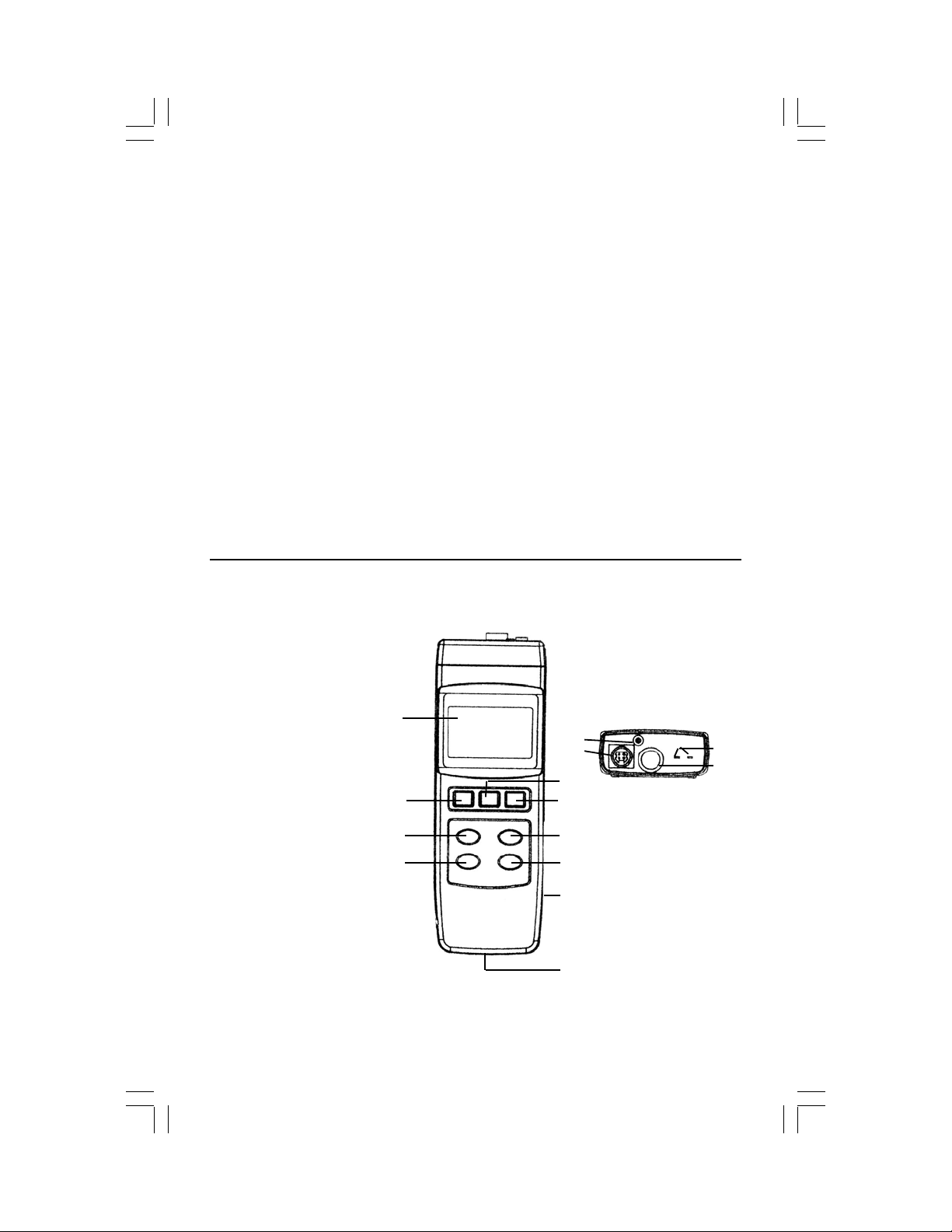
I. PANEL DESCRIPTION
1. LCD Display
2. POWER button
3. SENSOR &
4. REL (relative) &
button
5. HOLD & BACKLIGHT
(>2S
5) button
6. REC (record) &
MAX/MIN button
7. °C/°F &
button
8. EMISSIVITY
(EMIS>2S) &
LASER I/O button
9. RS-232 Output
Socket
10. Battery
Compartment
11. Thermocouple
Input Socket
(Type J/K/R/E/T)
12. Infrared (IR) Sensing
Head
13. Pt100
14. Laser Guide button
Õleft button
Ødown
×up
Ω Input Socket
Figure A
1
2
3
4
14
13
5
6
7
8
9
10
2
11
12
Page 3
II. INTRODUCTION Combines Infrared, RTD and thermocouple capabili-
ties in a single unit. For general purpose applications chose any type
K, J, R, E, or T thermocouple probe. For a precise temperature read-
ing use the PT100 RTD probe. The built-in IR thermometer features a
laser guide and adjustable emissivity. The distance-to-spot ratio is ap-
proximately 7:1. Other features include RS232 computer interface, C &
F selection, min-max memory, relative temperature, auto power off and
hold. Has a convenient tripod back and an easy to read back-lit display
with large ½" high digits.
LASER WARNING!
III. OPERATING INSTRUCTIONS - See Fig A, page 2 for button locations.
A. IR MEASUREMENT
1. Press the POWER button (2) to turn the unit on. The display will count
down from 99999, 88888, etc. to 00000, then show the IR temperature
and the emissivity on the LCD's right bottom corner.
2. Use the °C/°F button (7) to change scales.
3. Point the IR Sensing Head (12) at the object to be measured.
The meter will display the surface temperature.
EMISSIVITY - All objects emit invisible energy. The amount of energy is
emitted proportional to the object's temperature and it's ability to emit
energy. Emissivity is based on the material that the object is made of and
it's surface roughness. Emissivity values range from 0. 1 for highly
reflective objects, to 1.00 for a flat black surface. The probe of your IR
Thermometer senses energy and calculates the temperature based on the
amount of IR energy it receives, plus a factory set emissivity value of 0.95.
An emissivity value of 0.95 will cover 90% of the typical applications. If the
emissivity value of the measured material is not 0.95, you can adjust the
emissivity value. Matching the correct emissivity with the specific value of
the object is important in order to obtain the exact temperature.
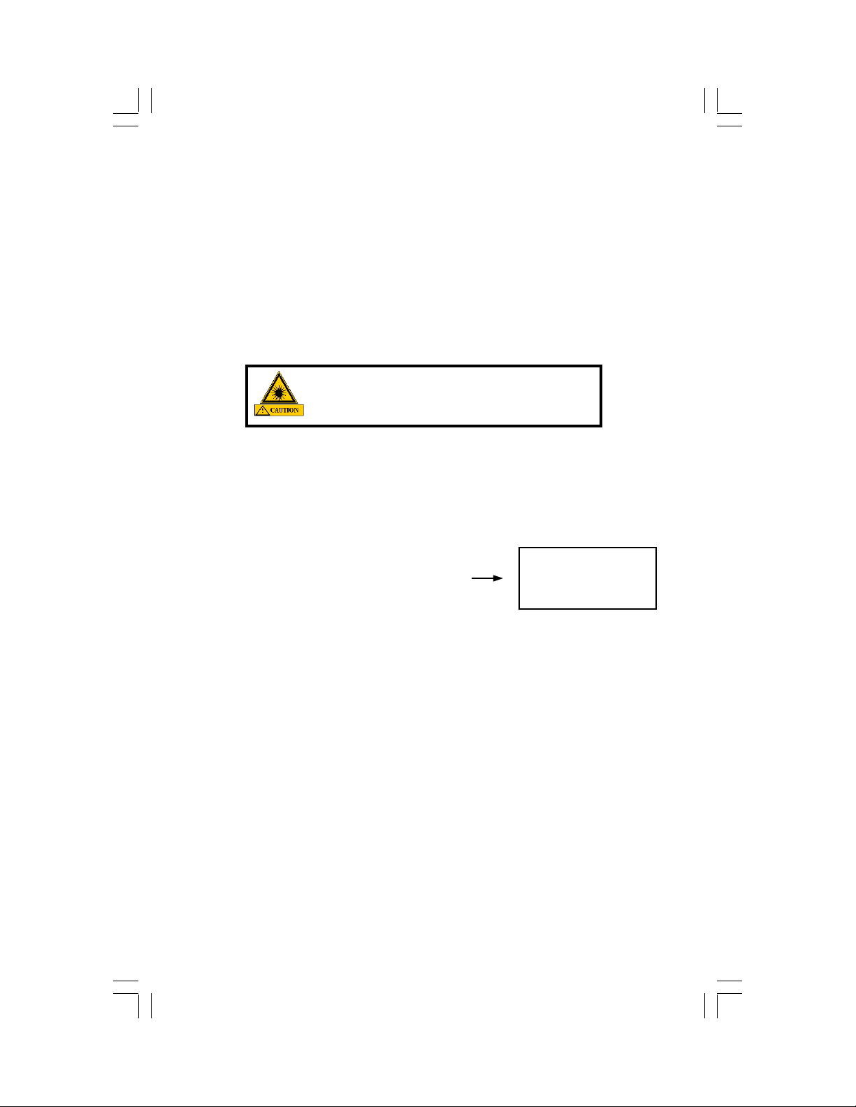
Press the EMISSIVITY button (8) for at least 2 seconds. Release the button when the emissivity value begins to flash. Use the Õleft button (2) to
select the digit and the
CAUTION: Do not point laser directly at eye.
Use caution around reflective surfaces. Keep
out of reach of children.
Example indicates a temperature of
74°F with emissivity of 0.95
×up (7) or Ødown (4) buttons to adjust the emissiv-
74
IR
°F
0.95
3
Page 4

DISTURBANCE - Objects with low emissivity or objects with a low
temperature and high emissivity, emit little infrared energy. For this
reason, measurement of these
objects is affected by infrared
energy radiated from nearby
objects with high emissivity or
high temperatures.
When such objects are measured
in sunlight for example, radiated
energy from the sun is reflected by
the surface of the object and
received by the sensor. Use a
shielding plate to block outside
infrared energy.
CALIBRATION - Check the unit against a known
standard. If the value has drifted, press and hold
down both the HOLD (5) and REC (6) buttons.
The temperature reading and the small digits in
the lower right corner will display the same value.
Continue pressing the HOLD and REC buttons
while using the ×up (7) or Ødown (4) buttons to
adjust the temperature reading to your standard.
The small digits retain your pre-calibration reading.
Release all buttons when you have reached the
adjusted temperature.
After releasing the buttons, the small digits will
disappear in Thermocouple or RTD modes and
the calibration is complete. In IR mode, the preset
emissivity will be displayed.
NOTES
• If the object you are measuring is covered with frost, clear the frost to
expose the object's surface before taking the measurement.
• If the surface you are measuring is highly reflective, apply masking
tape or a paint that has a 0.95 emissivity.
• The display may fluctuate if the meter is moved during measurement.
• The unit will automatically compensate for ambient temperature.
• For the most accurate measurement, allow the unit to adjust to the
ambient temperature for about 30 minutes before use.
• When a low temperature is measured directly after a high temperature
has been measured, the display may take some time to stabilize.
h
S
IR
IR
IR
a
l
P
g
n
i
d
l
e
i
74
76
76
Object
e
t
°F
74
°F
74
°F
0.95
4
Page 5

B. THEMOCOUPLE MEASUREMENT (K, J, T, E, R)
1. With the meter on, press the SENSOR button (3) to select your sensor
type. The display shows: IR, Pt3850, K, J,T, E, or R.
2. Insert the probe plug into the Thermocouple Input (11).
3. Press the °C/°F button (7) to select the temperature scale.
4. The LCD will display the temperature reading.
5. If needed, follow the Calibration Procedures on page 4.
NOTES
• Match the plug's polarity to the unit's polarity.
• To obtain the most accurate reading, the plug must stabilize at the
temperature of the socket. This will take a few minutes and only
applies if the probe plug has been exposed to an ambient temperature
different to that of the thermometer.
C. PT 100 OHM MEASUREMENT
1. With the meter on, press the SENSOR button (3) to select "Pt3850."
2. Insert the PT 100 probe into the Pt100Ω Input Socket (13).
3. Press the °C/°F button (7) to select the temperature scale. The LCD
will display the temperature reading.
4. If needed, use the Calibration Procedures on page 4.
D. DATA HOLD
1. Press the HOLD button (5) during measurement to freeze the
displayed measurement. "HOLD" and the measurement are displayed.
2. Press the HOLD button (5) again to exit this function.
E. DATA RECORD (Display the Maximum / Minimum Measurements)
1. With the meter on, press the REC button (6) once. "REC" and the
current measurement are displayed.
2. Press the REC button (6) again. "REC Max" and the maximum
recorded measurement are displayed.
3. Press the REC button (6) again. "REC Min" and the minimum
recorded measurement are displayed.
4. To exit this function, press and hold the REC button (6) for at least 2
seconds. The display reverts to the current reading.
F. RELATIVE MEASUREMENT
1. Press the REL button (4) during measurement to store the current
reading into memory. "REL" and a zero value appears on the LCD.
2. Subsequent readings will be measured and only the difference (higher
or lower) will be displayed.
3. Press the REL button (4) again to cancel this function.
4. Example: An IR measurement of 75°F was stored in memory by
pressing the REL button. The meter is then aimed at an object that's
temperature is 55°F. "REL" and "- 20°F" will be displayed.
5
Page 6

G. LCD BACK LIGHT - Press the BACK LIGHT >2S5 button (5) for at
least 2 seconds. The LCD will light for approximately 10 seconds, then
turn off.
H. AUTO POWER OFF - If no buttons are pushed for approximately
10 minutes, the meter will automatically turn off. To disable this feature,
select the Data Record function (page 5) by pressing the REC button
(6). "REC" will be displayed.
I. BATTERY REPLACEMENT - Accurate thermometer
readings may be taken for several hours after the low battery
indicator is displayed. Open the battery cover, install a fresh
9V battery and replace the cover.
J. RS232 PC SERIAL INTERFACE - This unit features an RS232
Output Socket (9) on the side of the unit. Gently lift the hinged cover
from the bottom. The output is a 16 digit data stream which can be
utilized by user's specific application. An RS232 lead with the following
connection is required to link the instrument with the PC serial input:
Meter (3.5 mm jack plug) PC (9W "D" Connector)
Center Pin Pin 4 Pin 2 2.2K
Ground/Shield Pin 2 Pin 5 resister
RS232 FORMAT: 9600, N, 8, 1
The 16 digit data stream will be displayed as follows:
D15D14D13D12D11D10D9D8D7D6D5D4D3D2D1D0
Each digit indicates the following status:
D0 End Word
D1 & D8
D9
D10 0 = Positive, 1 = Negative
D11 & D12 Anunuciator for Display: 01=°C, 02=°F
D13 1
D14 4
D15 Start Word
Display reading, DI " LSD, D8 MSD. For example: If the
display reading is 1234, then D8 to D I is: 00001234
Decimal Point(DP), position from right to the left
0 = No DP, 1 = 1 DP, 2 = 2 DP, 3 = 3 DP
6
Page 7

IV. SPECIFICATIONS
Type Range Res Accuracy (meter only)
PT 100 -200 ~ 850°C, -328 ~ 1562°F
Type K -100 ~ 1300°C, -148 ~ 2372°F
Type J -100 ~ 1150°C, -148 ~ 2102°F
± 0.2%+0.5°C or 1°F
0.1°
Type T -100 ~ 400°C, -148 ~ 752°F
Type E -100 ~ 900°C, -148 ~ 1652°F ± 0.2%+0.5°C or 1°F
±1%+5°C
Type R 0 ~ 600°C
601 ~ 1700°C
32 ~ 1112°F
1113 ~ 3092°F
Infrared -20 ~ 400°C
-4 ~ 752°F
±1.5%+5°C
±1%+10°F
±1.5%+10°F
1°
±3% rdg or ±3°C or ±5°F
(which ever is greater)
Note: Accuracy is tested within 23 ± 5°C.
Display 2" x 11/4" (51mm x 32mm) and 1/2" (15mm) digits.
Sensor Types 1. Non Contact Infrared thermometer
2. Platinum PT 100 ohm (0.00385 alpha coefficient,
meets DIN IEC 751 standards)
3. Thermocouple probes: K, J, T, E, R
Circuit Exclusive microcomputer circuit with built-in linearity
correction function. The Pt 100 ohm's curve is stored
in the CPU circuit.
Laser Red laser light guide, less than 1mW meets EN60825
standards
Probe Input 1. PT 100 ohm probe: DIN 4 pin socket
2. Thermocouple probe: Standard 2 pin socket
Sampling
Approximately 1 second
Time
Over Range
" - - - - "
Indicator
Data Output RS232 PC serial interface
Operating
32 ~ 122°F, 0 ~ 50°C and less than 80% relative humidity
Temp/RH
D/S Distance-to-Spot ratio is approximately 7:1.
7
Page 8

Power Supply Alkaline or heavy duty type, DC 9V battery.
Power Consumption Approx DC 11 mA (w/o laser light on).
Approx DC 16 mA (with laser light on).
Above consumption value is calculated using the
IR thermometer without LCD backlight.
Size HWD 200x 68 x 30mm (7.9 x 2.7 x 1.2")
Weight 8 oz, 220 g
IR Wavelength Reg. 6 to 12 micrometer
Input Socket DIN 4 pin socket
V. OPTIONAL ACCESSORIES
• 800044 Replacement PT 100 Probe
• 840057 RS232 Cable
• 840094 USB Cable Adaptor
• 840090 Water Resistant Instrument Pouch
• 840092 Bench Top Tripod
• 840093 Field Tripod
• 850080 Data Acquisition Software
VI. WARRANTY Sper Scientific warrants this product against defects in
materials and workmanship for a period of FIVE (5) YEARS from the date
of purchase, and agrees to repair or replace any defective unit without
charge. If your model has since been discontinued, an equivalent Sper
Scientific product will be substituted if available. This warranty does not
cover probes, batteries, or damage resulting from accident, misuse, or
abuse of the product. In order to obtain warranty service, simply ship the
unit postage prepaid to:
SPER SCIENTIFIC, 7720 E Redfield, Ste 7, Scottsdale, AZ 85260
480-948-4448, www.sperscientific.com, info@sperscientific.com
The defective unit must be accompanied by a description of the problem
and your return address. Register your product online or return your
warranty card within 10 days of purchase.
Rev 6/26/06
8
 Loading...