

Page 1

Light Meter (Foot Candles)
840021
Instruction Manual
SPER
SCIENTIFIC
LTD.
Page 2

TABLE OF CONTENTS
1. INTRODUCTION ..................................................................................... 2
2. PANEL DESCRIPTION .......................................................................... 3
3. MEASUREMENT PROCEDURES .......................................................... 4
4. ZERO ADJUSTMENT & CALIBRATION ............................................... 5
5. BATTERY REPLACEMENT ................................................................. 5
6. OPTIONAL ACCESSORIES ................................................................. 5
7. SPECIFICATIONS .................................................................................. 6
8. LIGHT SENSOR SPECTRUM ................................................................ 7
9. WARRANTY ........................................................................................... 8
1. INTRODUCTION
Compact and portable, your new meter can be used to monitor light levels or
check the FC level of a particular light source. The sensor's exclusive photo
diode and color correction filter meets the C.I.E. photopic spectrum.
Sper Scientific light meters are cosine corrected for a quick and accurate
response. Large easily legible 4 digit LCD. The meter has an external zero
adjustment, data hold, low-battery indicator, and a moisture resistant front
panel.
Comes with soft carrying case, detachable light sensor, photo-sensor cover,
instructions and a 9-Volt battery.
- 2 -
Page 3
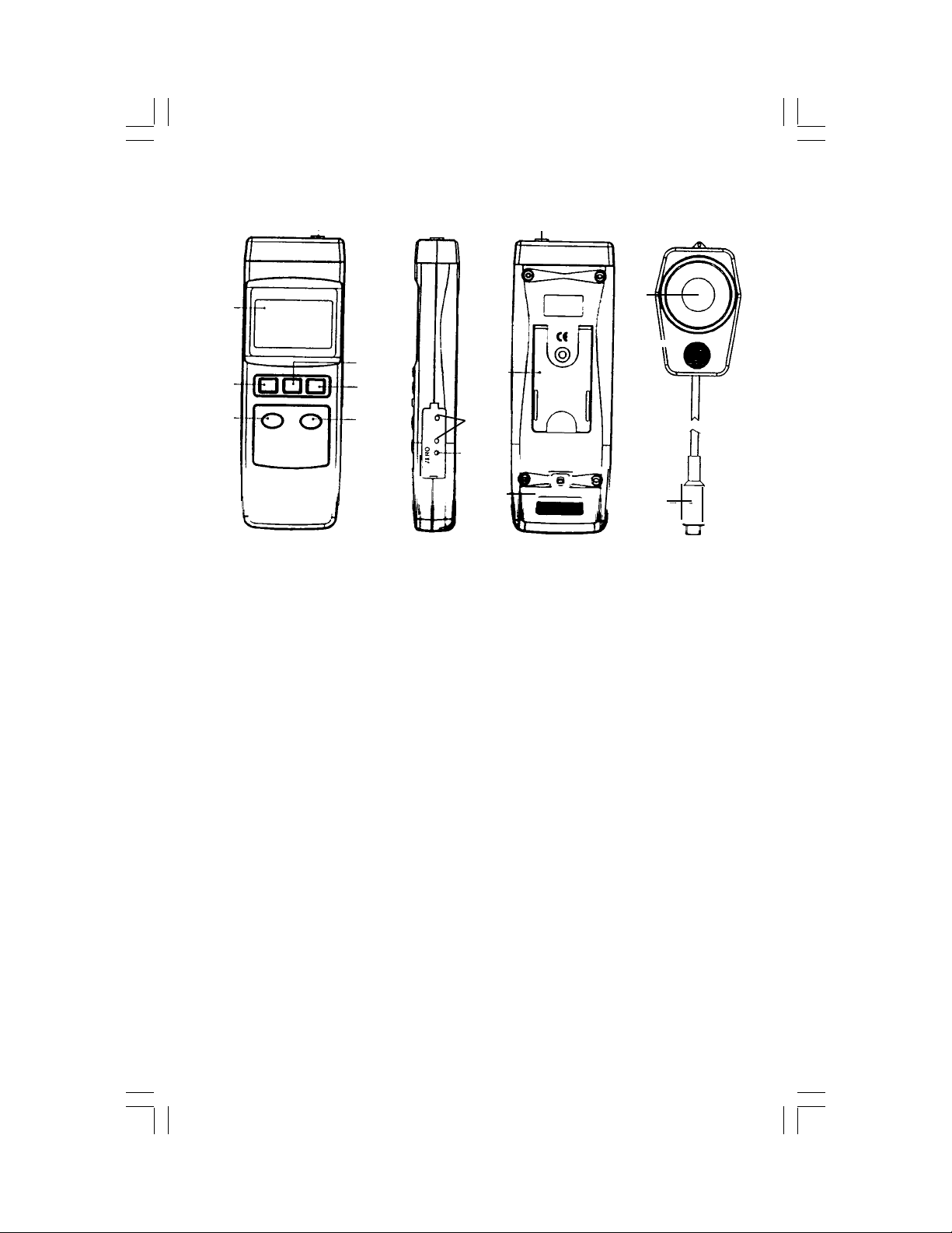
2. PANEL DESCRIPTION
8
1
3
2
4
6 5
1. DISPLAY
2. ON BUTTON
3. OFF BUTTON
4. HOLD BUTTON
5. 200 RANGE BUTTON
6. 2000 RANGE BUTTON
laboratory calibration only
7
10
11
9
12
7. ZERO SETTING TERMINAL
8. SENSOR INPUT SOCKET
9. STAND
10. BATTERY COMPARTMENT
11. PHOTO SENSOR
12. SENSOR PLUG
- 3 -
Page 4

3. MEASUREMENT PROCEDURES
• Insert the SENSOR (12) plug into the SENSOR INPUT (8) socket.
• Turn the meter on using the ON (2) button.
• Remove the lens cap from the PHOTO SENSOR (11).
• Press the 200 RANGE (5) button for measurements of 0 ~ 199.9 FC, or
select the 2000 RANGE (6) button for measurements of 200 ~ 1999.9 FC.
If you are uncertain about which range to use, select the highest range.
• Range Overload is indicated when "1" appears on the left side of the
display. If this occurs, switch to the highest range or discontinue use.
• Point the PHOTO SENSOR (11) toward the source and read the results
on the display. Divide the meter reading by the factor of .0929 to convert
FC results to LUX.
• Push the HOLD (4) button to freeze the reading in the display. The word
"HOLD" appears on the LCD. Press the HOLD (4) button again to exit
this function.
• Press the OFF (3) button to turn the unit off.
Notes:
• Keep the lens cap on the PHOTO SENSOR (11) at all times except when
actually taking a reading.
• Fluctuations in the reading are generally due to shadows or fluctuations in
the line voltage. Ambient temperature, drafts and ventilation also affect
the luminous flux output.
• Avoid range overload and do not store in areas of high temperature
and / or humidity. Remove the battery for long-term storage.
- 4 -
Page 5
4. ZERO ADJUSTMENT & CALIBRATION
IMPORTANT: During adjustment, be sure to use only the terminal marked
"ZERO." The unmarked terminals are for professional laboratory calibration only. Tampering with the unmarked terminals will result in inaccurate
readings and require professional calibration of the meter.
• With the sensor cover securely in place and the meter turned on, the
LCD display should indicate "000" or "00.0" depending on the selected
range.
• A slight variation will not affect readings; however, if a precise reading
is required you may use the ZERO SETTING (7) terminal to reset the
unit.
• To make an adjustment, press the 200 RANGE (5) button and cover
the PHOTO SENSOR (11).
• Using a small screwdriver, turn the ZERO SETTING (7) terminal until
"00.0" appears on the LCD.
• To maintain accuracy, annual laboratory calibration is recommended.
For calibration service, contact SPER SCIENTIFIC, 7720 E Redfield
Rd, Suite 7, Scottsdale, AZ 85260, USA. Ph 480-948-4448,
[email protected].
5. BATTERY REPLACEMENT
• Replace the battery when the low battery icon is displayed in
the left corner of LCD.
• In-spec measurements may be made for several hours after the low
battery indicator appears.
• Remove the BATTERY COMPARTMENT (10) screw and slide the
cover away from the meter, remove the battery and replace with a 9V
battery (alkaline or heavy duty type).
• Replace the cover.
6. OPTIONAL ACCESSORIES
• 840090 Water Resistant Instrument Pouch
• 840092 Bench-Top Tripod
• 840093 Field Tripod
- 5 -
Page 6
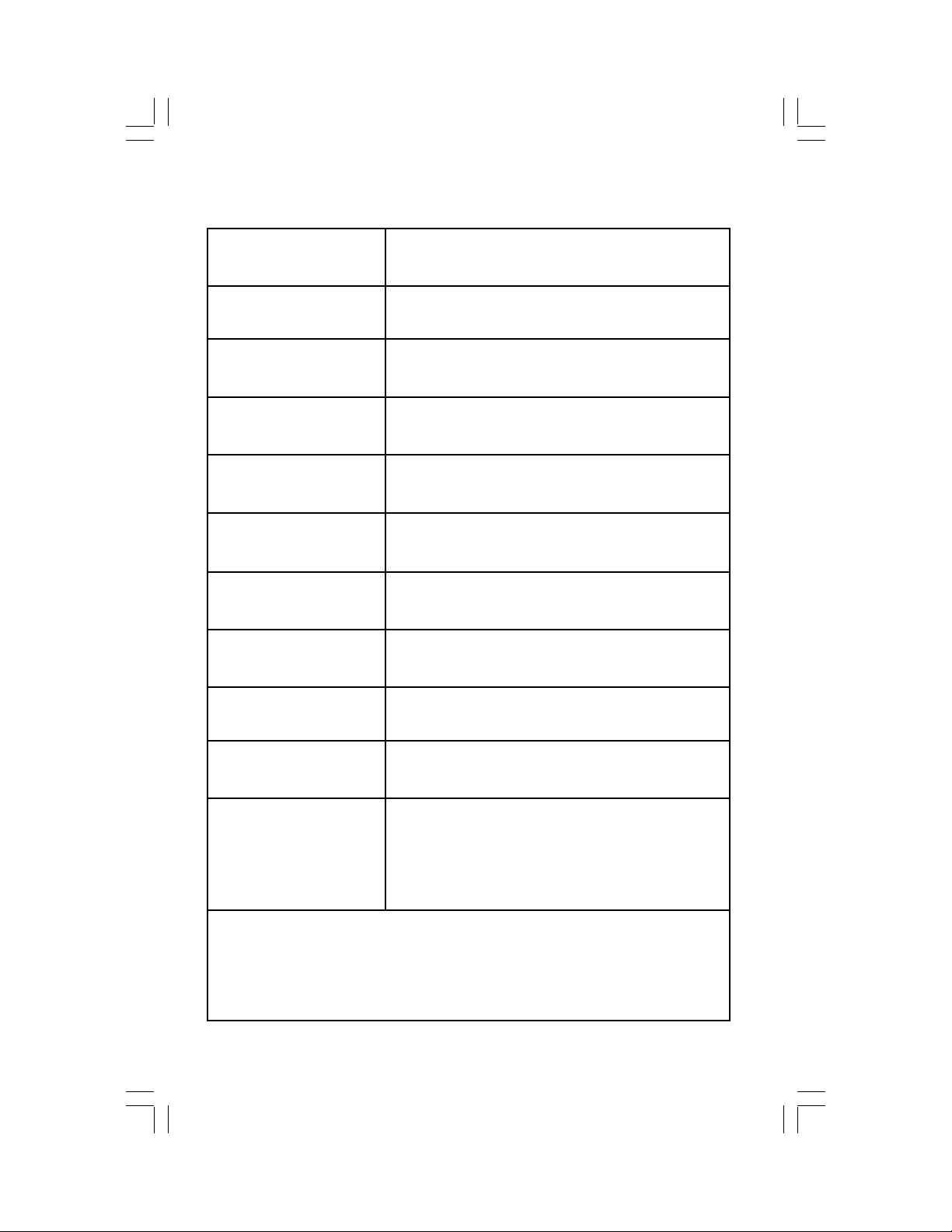
7. SPECIFICATIONS
Display Maximum reading 1999
Overload Indicator "1" is displayed on the left of the LCD
The exclusive photo diode and color correction
Sensor
Power Supply One 9V battery, current approx. DC 3mA
filter, spectrum meets C.I.E.
Cosine correction factor meets the standard.
Range*
Resolution*
Accuracy* ±5% + 4 digits
Operating Temperature 32 ~ 122°F (0 ~ 50°C)
Operating Humidity Less than 80% RH
Weight 9.9 oz (280g)
Dimensions
200 Range = 0 ~ 199.9 Foot Candle
2000 Range = 200 ~ 1999 Foot Candle
200 Range = 0.1 Foot Candle
2000 Range = 1 Foot Candle
Main Unit: 7.9 x 2.7 x 1.2" (200 x 68 x 30mm)
Photo Sensor: 3.2 x 2.2 x 0.3" (82 x 55 x 7mm)
Photo Sensor Lead: Extends to appx. 3½ ft
*Electronic Specifications (23 ± 5°C): Tested under the environment RF
Field Strength less than 3 V/M, and frequency less than the 30 MHz only.
- 6 -
Page 7
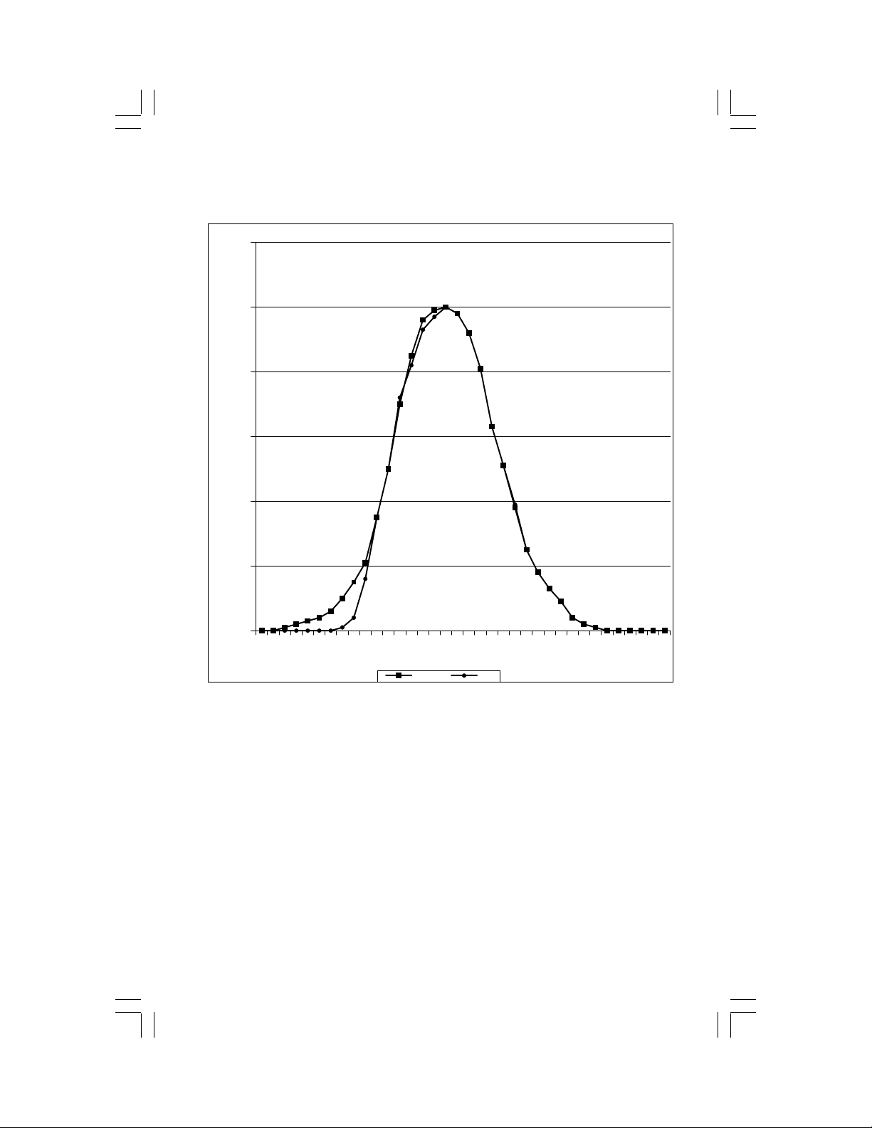
8. LIGHT SPECTRUM SENSOR
120
100
80
60
40
20
0
410
430
450
470
490
510
530
550
570
590
610
630
650
670
690
710
730
SPER CEI
- 7 -
750
Page 8

WARRANTY
Sper Scientific warrants this product against defects in materials and
workmanship for a period of FIVE (5) years from the date of purchase,
and agrees to repair or replace any defective unit without charge. If your
model has since been discontinued, an equivalent Sper Scientific product
will be substituted if available. This warranty does not cover damage
resulting from accident, misuse, or abuse of the product. In order to obtain
warranty service, ship the unit postage prepaid to:
SPER SCIENTIFIC LTD.
7720 E Redfield Rd, Suite 7, Scottsdale, Arizona 85260, USA
ph. 480-948-4448, [email protected], www.sperscientific.com
The defective unit must be accompanied by a description of the problem
and your return address. Please be sure to register online or return your
warranty card within ten (10) days of purchase.
Rev. 05/11/06
- 8 -
 Loading...