

Page 1
4 Channel
Datalogging
Thermometer
800024
INSTRUCTION MANUAL
SPER
SCIENTIFIC LTD.
304
SETUP
HOLD
CLOCK
REC
200
C
328
F
POWER-UP OPTIONS
REC
800024
T1-T2
INTV
C
1370RANGE
2498
F
C
F
Page 2

CONTENTS
TITLE PAGE
I. Introduction
…………………………………………………………………………….…..1
II. Specifications
……………………………………………………………………………
III. Symbol Definition and Button Location
……………………………….2
IV. Operation Instructions…………………………………………….………… ……
4.1 Power-Up & turn ON/OFF backlight
4.2 Connection the Thermocouples………………………………………………………....3
4.3 Selecting the Temperature Scale………… ……………………………………………..
3
4.4 Data-Hold Operation…………………………………………………………………….…
4.5 T1-T2 Operation……………………………………………………………………………
3
4.6 Record and Erase memory Operation
3
4.7 Clock Setup…………………………………………………………………………………
4.8 Recording Interval Setup………… ………………………………………………………
4
4.9 MAX/MIN Operation
4.10 Auto Power Off…………….……………………………………………………………...
4.11 Low Battery Condition ………………………………… .……………………………. ..
4
4.12 Calibration Point………………………………………………………………………….
4
4.13 Digital Output……………………...………………… …………………………………...
4
V. Setup TestLink SE-309—RS232 interface softwar e
(Appendix: Thermocouple probe specification)…….………………………………………5
………………………………………………………………………..
………………………………………………….....3
……..………….………………………………
………….… 5
1
1
3
3
3
4
4
Page 3
I. Introduction:
y
This instrument is a four channel digital thermomete r for use with any K-type thermocouple as
temperature sensor. Temperature indication follows National Bureau of Standards and IEC584
temperature/voltage table for K-type thermocouples. It internal memory can keep up to 16,000
records per channel. (note1.) It uses RS232 interfa ce to perform bi-directional communication with
PC.
II. Specifications:
Numerical Display:
Measurement Range:
Resolution:
Input Protection at Thermocouple Input: 60V DC, or 24Vrms AC
Environmental:
ο Operating Temperature and Humidity: 0°C ~50°C (32°F ~ 122°F) ; 0 ~ 80% RH
ο Storage Temperature and Humidity: -10°C to 60°C (14°F ~ 140°F); 0 ~ 80% RH
ο Altitude up to 2000 meters.
Accuracy: at ( 23 ± 5°C )
-200°C ~ 200°C ±(0.2% reading + 1°C)
200°C ~ 400°C ±(0.5% reading + 1°C)
400°C~1370°C ±(0.2% reading + 1°C)
-328°F ~ -200°F ±(0.5% reading + 2°F)
-200°F ~ 200°F ±(0.2% reading + 2°F)
200°F ~ 2498°F ±(0.3% reading + 2°F)
The basic accuracy Specification does not include the error of the probe. P lease refer to the
probe accuracy specification for additional details.
Electromagnetic Compatibility: Total accuracy = specified accuracy ±2°C(3.6°F)
Sample Rate:
Dimension: 184×64×30mm
Weight:
Accessory: K Type Bead Probe×2, Batt ery, Carrying Case, Instruction Menu, Software progra m,
Power requirement:
Battery Life: Approx. 100hrs with alkaline battery
AC Adapter:
Plug Diameter: 3.5mm×1.35mm
Option :
note1:
4 digital Liquid Crystal Display per channel.
-200°C ~ 1370°C -328°F ~ 2498°F
-200°C~ 200°C 0.1°C; 200°C ~1370°C 1°C
-200°F~ 200°F 0.1°F; else 1°F
Range Accuracy
Temperature Coefficient:
For ambient temperatures from 0°C ~ 18°C and 28°C
~ 50°C, for each °C ambient below 18°C or above
28°C add the following tolerance into the accurac
spec.
0.01% of re ading + 0.03°C
( 0.01% of reading + 0.06°F )
Note:
3 seconds per period
250g Approx.
RS-232 Connection Cable
9 Volt Battery
9VDC ±15% 100mA
AC Adapter
Every time you press "REC" button to start recording data and press "REC" button again to st op
recording, there will be a data set in memory, you can store as many data sets as you want until memory
is full.
2
Page 4

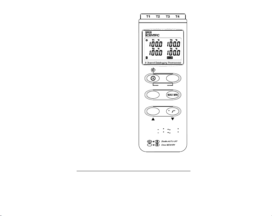
III. Symbol Definition and Button Location:
: This indicates that the minus temperature is sensed.
: Centigrade and Fahrenheit indication.
: Thermocouple Type Indication.
: The Maximum value is now being displayed.
: The Minimum value is now being displayed.
: This indicates auto power off is enabled.
: This indicates that the display data is being held.
: The Battery is not sufficient for proper operation.
: It indicates the value below is T1, T2, T3, T4 Temperature sensor.
T1,T2,T3,T4
: It indicates the value below is T1-T2 sensor.
: The reading is now under relative mode.
: This indicates that the tester is recording. If it blinks, it indicates the memory is full.
MAX
24V
T2
T1T4T3
60V
1
2
3
4
5
POWER-UP OPTIONS
REC
6
T1-T2
SETUP
7
HOLD
INTV
CLOCK
REC
CF
200
1370RANGE
328
2498
FCF
CAL
8
OUTPUT
DC9V
C
Button Location:
1
•
K type temperature sensor T1 to T4
input connector
2
•
LCD display
3
•
ON/OFF & Backlight button
4
•
Hold button
5
•
Record button
6
•
T1-T2 button
7
•
MAX MIN function control button
8
•
°C, °F control button
9
•
Offset calibration screw
9V BATTERY
9
NEDA 1604 6F22 006P
MANUAL FOR SAFETY
PLEASE READ
OPEN
10
•
Digital output connector
11
•
AC power adapter connector
12
•
Tripod connector
13
•
Battery cabinet cover
3
Page 5

IV. Operation Ins tructions:
4.1 Power-Up & Turn ON/OFF backlight
I
The •
key turns the Thermometer ON or OFF and backlight ON & OFF.
Press it once to turn on the Thermometer.
Press it again for moment to turn ON or OFF backlight.
Press and hold this button 3 second to turn OFF the power.
4.2 Connection the Thermocouples
For measurement, plug the thermocouple into the input connectors.
4.3 Selecting the Temperature Scale
When the meter was powered on, the user may chang e it to Fahrenheit (°F) by pressing “
button and vice versa to Celsius.
4.4 Data-Hold Operation
The user may hold the present reading and k eep it on the display by pressing the “
When the held data is no longer needed, one may release the data-hold operation by pressing
“HOLD” button again.
When the meter is under Data Hold op eration, the “MAX MIN”,“T1-T2” and “°C/°F” button are
disabled. (when you press “ °C/°F ”, “T1-T2” and “MAX MIN” button in HOLD mode, there will be
two continuous beeps)
4.5 T1-T2 Operation:
When this button is pushed, “
right hand side LCD display to indicate th at the tester is under T1
minus T2 mode. The temperature differenc e is shown on the right
hand side display as shown in Fig.
4.6 Record and Erase memory Operation:
When one presses the "REC" button, the m eter will start recording, and
pressing the "REC" button again will stop recording, If you want to clear the
memory, power off the meter, then press and hold “REC” button and then press
power button and hold at least 5 seconds, then LCD will show "CLR" “S URE 5”,
then release all buttons to clear the memory.
4.7 Clock Setup :
4.8 Recording Interval Setup :
” will be shown on the upper
1 – 2
1: press and hold “T1-T2” button and then power on the meter:
2: press “HOLD”(clock):
3: press "REC" • or "°C/°F"
press “HOLD”(clock) to adjust next item. The adjusting order is
year•month•day•hour•minute, then press “HOLD” (clock) to finish
adjusting. If you want abort during a setup process, press power
button to cancel.
1: press and hold “T1-T2” button and then power on the meter:
2: press “MAXMIN"(INTV)
•
to increase or d ecrease number,
HOLD
°C/°F
” button.
4
”
Page 6

3: press "REC" • or "
press “MAXMIN " (INTV) to adjust next item, then press “MAXMIN”
(INTV) to finish. If you want abort durin g a setup process, press
4.9 MAX/MIN Operation:
When pressing the "MAX MIN" button the mete r will enter the MAX/MIN mode. Under th is mode the
maximum value, minimum value is kept in the memory simultaneously and up dated with every new
sample of data.
When the MAX symbol is display, the Maximum is shown on the display.
Press "MAX MIN" again, then the MIN symbol is on the display and also the minimum reading.
Press "MAX MIN" again, MAX, and MIN will blink together. This means that all these data is
updated in the memory and the reading is the present temperature.
One may press "MAX MIN" to circulate the display mode among these options.
When the meter is under "MAX MIN" operation and “ °C/°F ” button are disabled.(when you press
“ °C/°F ” button in "MAX MIN" mode, there will be two continuous beep)
To exit the MAX/MIN mode, one may press and hold "MAX MIN" for two seconds.
4.10 Auto Power Off:
By default, when the meter is powered on, it is und er auto power off mode. The meter will power
itself off after 30 minutes if no key operation and no RS232 c ommunication combination at power on
can disable auto power off.
One may press and hold “
successive beeps to indicate that auto power off is disabled and the will not show up.
4.11 Low Battery Condition
When the battery voltage is under proper operation requirement, the symbol will show on the
LCD and the battery need to be replaced with new one.
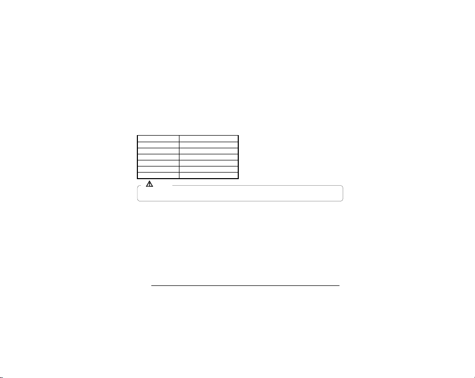
4.12 Calibration Point:
input Adjust VR tolerance
0 °C VR1 ± 0.1 °C
190 °C VR2 ± 0.1 °C
1000 °C VR3 ± 1 °C
1900 °F VR4 ± 1 °F
4.13 Digital Output:
The Digital Output is a 9600bps N 81 serial interface.
The RX is a 5V normal high input port.
The TX is a 5V normal high output port.
power button to cancel.
” button and then power on the me ter and there will be two
HOLD
• to increase or decrease number,
°C/°F"
P.S
Normally, performing offset Calibration with thermal
stabled ice water through VR1 will give a very good
calibration result.
TXRXGND
V. Setup TestLink SE-309 —RS23 2 interface softwar e:
The TestLink package contains:
1.80mm CD.
2.Custom designed RS232 cable for TestLink.
System Required:
Windows 95 or Windows 98 or Windows NT 4.0 above.
Minimum Hardware Required:
PC or NoteBook with Pentium 90MHz or higher, 32 MB
5
Page 7

RAM ;
At least 5 MB byte hard disk space available to install
TestLink. Recommended resolution 800X600.
Install TestLink:
1.We recommend close all other application before installing TestLink.
2.Insert setup CD disk to CD disk drive.
3.Choose the Start button on the Taskbar and select Run.
4.Type E:\SETUP and choose OK, then it will copy SE309.exe ( executable file ) and he lp file to
your hard disk ( default is c:\program files\TestLink\SE309 ).
For detailed other operation instruction, please refer to the online help while executing SE309.
Appendix: Thermocouple probe specification
Model Range Tolerances Description
TP-K01
-50• to 200•
Bead probe
TP-K01:
probe for general condition measurements, especially for
complex and hard to reach places.
-58• to 392•
±2.2• or ±0.75•
(±3.6• or ±0.75•)
with Teflon tape insulation Maximum
insulating temperature : 260•
6
 Loading...