

Page 1

Instruction Manual
Bedienungsanleitung
Manuel d’utilisation
Manuale di Istruzioni
Page 2

About Quique
t began in Argentina with his father, Mario. Throughout the late 1970’s,
I
Mario Somenzini was the reigning F3A Champion of Argentina and most
of South America. As a boy, Quique would spend hours with his father at
the fl ying fi eld cleaning airplanes, watching and learning. It paid off.
In 1976, Quique made his fi rst RC solo
fl ight at the age of 9. Just three years
later, he followed in his father’s footsteps and won his fi rst Argentina F3A
National Championship. That same year
he had the privilege of representing his
country at the F3A World Championships in South Africa. He didn’t win,
but he did set a record of sorts as the
youngest pilot ever to compete for an
F3A world title; a record that still stands
today.
In the years that followed, Quique won
a host of other titles, including 17 more
Argentina F3A national championships, four U.S. F3A national championships, four 1st place TOC fi nishes and one F3A world championship. But
if you ask him, there is one RC title Quique cherishes above all
others - “The Father of 3D”. Around the world, RC pilots point to his
pioneering efforts in perfecting the art of fl ying aerobatics beyond the stall
as the birth of 3D aerobatics.
Today, Quique Somenzini remains one of the most dynamic and infl uential
forces in RC fl ight; one that will be shaping the future of the sport for
years to come.
• 4 Time TOC Champion
• F3A World Champion
• 4 Time US F3A National Champion
• Free Style World Champion
• 2 Time Tucson Shootout Free Style Champion
• XFC Champion
• 3 Time Don Lowe Master Champion
• 17 Time Argentina F3A National Champion
• 6 Time South America F3A Champion
• 20 years in top ten F3A world championships including 3 times runner
up places.
• Has competed at the world class level for 30 years.
• Still holds the world record as the youngest pilot ever to compete in
F3A World Championship.
2
EN
SPEKTRUM DX18QQ
Page 3

Sol de Mayo
he Sol de Mayo (Sun of May) symbol on the SpektrumTM DX18QQ
T
transmitter case comes from the national fl ag of Quique’s native
country of Argentina. It’s just one of the many personal touches that
Quique and the Spektrum team have included to make the DX18QQ unlike any transmitter you’ve fl own with before.
ongratulations on the purchase of your DX18QQ! I’m very excited
C
about this transmitter. So many people were involved in making
this project a reality and we all want to say thank you for choosing to
make it such a central part of your fl ying experience. I’m confi dent
you’re going to love its elegant style and exclusive features every bit
as much as I do.
Best regards. QQ
Exclusive DX18QQ Features:
• “Roll” between telemetry, monitor and main screens without entering
the Settings menu
• Switch between Function List and System Settings menus without
powering off the transmitter
• Program mixes of less than 10% can be adjusted in 0.5% increments
• 6-Servo wing setup
• Canard options (1- and 2-servo Rudder) are available under tail type
when the elevon wing type is selected
• Origin mixing
• Selectable sound menu lets you activate or inhibit specifi c DX18QQ
sounds
• Assign fi ve Airplane fl ight modes to any combination of up to three
switches
• Expanded selection of avatar choices for model memory identifi cation
• Assign in-fl ight aircraft gyro gain adjustment to one of the side levers,
the right knob, or one of the auxiliary trim switches at the top of the
transmitter faceplate
• Pitch curve for Airplane models with variable pitch props
• Turn the throttle trim into a 3-position switch for turbine engine start
up ease
www.spektrumrc.com
EN
3
Page 4

NOTICE
All instructions, warranties and other collateral documents are subject to change
at the sole discretion of Horizon Hobby, Inc. For up-to-date product literature, visit
horizonhobby.com and click on the support tab for this product.
Meaning of Special Language
The following terms are used throughout the product literature to indicate various levels of potential harm when operating this product:
NOTICE: Procedures, which if not properly followed, create a possibility of
physical property damage AND little or no possibility of injury.
CAUTION: Procedures, which if not properly followed, create the probability
of physical property damage AND a possibility of serious injury.
WARNING: Procedures, which if not properly followed, create the probability
of property damage, collateral damage and serious injury OR create a high
probability of superfi cial injury.
WARNING: Read the ENTIRE instruction manual to become familiar with
the features of the product before operating.
Failure to operate the product correctly can result in damage to the product,
personal property and cause serious injury.
This is a sophisticated hobby product. It must be operated with caution and
common sense and requires some basic mechanical ability. Failure to operate this
Product in a safe and responsible manner could result in injury or damage to the
product or other property. This product is not intended for use by children without
direct adult supervision. Do not attempt disassembly, use with incompatible components or augment product in any way without the approval of Horizon Hobby,
Inc. This manual contains instructions for safety, operation and maintenance. It
is essential to read and follow all the instructions and warnings in the manual,
prior to assembly, setup or use, in order to operate correctly and avoid damage or
serious injury.
WARNING AGAINST COUNTERFEIT PRODUCTS
Always purchase from a Horizon Hobby, Inc. authorized dealer to ensure
authentic high-quality Spektrum product. Horizon Hobby, Inc. disclaims all support
and warranty with regards, but not limited to, compatibility and performance of
counterfeit products or products claiming compatibility with DSM or Spektrum.
NOTICE: This product is only intended for use with unmanned, hobby-grade,
remote-controlled vehicles and aircraft. Horizon Hobby disclaims all liability outside of the intended purpose and will not provide warranty service related thereto.
Age Recommendation: Not for Children under 14 years. This is not a toy.
Warranty Registration
Visit community.spektrumrc.com today to register your product.
NOTICE:
While DSMX allows you to use more than 40 transmitters simultaneous-
ly, when using DSM2 receivers, DSMX receivers in DSM2 mode or transmitters in
DSM2 mode, do not use more than 40 transmitters simultaneously.
4
EN
SPEKTRUM DX18QQ
Page 5

General Notes
• Models are hazardous when operated and maintained incorrectly.
• Always install and operate a radio control system correctly.
• Always pilot a model so the model is kept under control in all conditions.
• Please seek help from an experienced pilot or your local hobby store.
• Contact local or regional modeling organizations for guidance and instructions
about fl ying in your area.
• When working with a model, always power on the transmitter fi rst and power
off the transmitter last.
• After a model is bound to a transmitter and the model is set up in the transmitter, always bind the model to the transmitter again to establish failsafe
settings.
Pilot Safety
• Always make sure all batteries are fully charged before fl ying.
• Time fl ights so you can fl y safely within the time allotted by your battery.
• Perform a range check of the transmitter and the model before fl ying the
model.
• Make sure all control surfaces correctly respond to transmitter controls before
fl ying.
• Do NOT fl y a model near spectators, parking areas or any other area that
could result in injury to people or damage to property.
• Do NOT fl y during adverse weather conditions. Poor visibility, wind, moisture
and ice can cause pilot disorientation and/or loss of control of a model.
• When a fl ying model does not respond correctly to controls, land the model
and correct the cause of the problem.
BEFORE USING YOUR TRANSMITTER:
Before going any further, visit the Spektrum Community website
at community.spektrumrc.com to register your transmitter and
download the latest AirWare™ fi rmware updates. A registration
reminder screen occasionally appears until you register your
transmitter. When you register your transmitter, the reminder screen
does not appear again.
Box Contents
• DX18QQ Transmitter
• 2600mAh LiPo Transmitter Pack
(Installed in transmitter)
• SPMAR12120 12 Channel
™
PowerSafe
• X-Plus 8 module
• SPM6803 Male/Female Bind plug
• Global Power Supply
• DX18QQ Transmitter case
www.spektrumrc.com
X-PlusTM Receiver
• DX18QQ SD card
• Neck strap
• 34mm optional stick ends
(24mm stick ends installed)
• Decal sheet
• Flashlight
• Microfi ber cloth
• Hat
• Manual
EN
5
Page 6

Table of Contents
System Overview
Transmitter Batteries ................................................................................... 8
Charging Your Transmitter ..............................................................................8
Transmitter Functions ............................................................................... 10
Main Screen ............................................................................................... 12
Navigation .................................................................................................. 13
Binding ....................................................................................................... 14
Programming Failsafe Positions ............................................................... 15
SmartSafe Failsafe ......................................................................................15
Hold Last Command .................................................................................... 15
Preset Failsafe ............................................................................................15
X-Plus 8 ...................................................................................................... 16
Installation .................................................................................................. 16
X-Plus Channels and Failsafe ....................................................................... 18
SD Card ......................................................................................................19
Model Type Programming Guide ......................................... 20
Common System Setup FunctIons ...................................... 22
Model Select ...............................................................................................22
Model Type .................................................................................................22
Model Name ...............................................................................................22
F-Mode Setup ............................................................................................. 23
Flight Mode Name Setup .............................................................................23
Aircraft and Sailplane Flight Mode Table .......................................................23
Channel Assignment....................................................................................24
Channel Input Confi guration .........................................................................24
X-Plus Input Confi guration ...........................................................................24
Trim Setup ..................................................................................................25
Model Copy ................................................................................................26
Model Reset ...............................................................................................26
Warnings ....................................................................................................26
Telemetry ...................................................................................................27
Prefl ight Setup ............................................................................................28
Frame Rate .................................................................................................28
Bind ........................................................................................................... 28
Trainer ........................................................................................................29
Analog Switch Setup ...................................................................................29
System Settings ..........................................................................................30
Inactive Alarm .............................................................................................32
Extra Settings .............................................................................................32
Serial Number .............................................................................................33
Calibrate ..................................................................................................... 33
Transfer SD Card .........................................................................................34
Function List ........................................................................ 36
Servo Setup ................................................................................................36
D/R & Expo .................................................................................................37
Differential (Air And Sail Types Only) .............................................................38
V-Tail Differential (Air And Sail Types Only) ....................................................38
Throttle Cut ................................................................................................38
Throttle Curve .............................................................................................39
Mixing ........................................................................................................ 39
Sequencer .................................................................................................. 41
Range Test .................................................................................................. 42
Timer .........................................................................................................43
Telemetry ...................................................................................................43
System Setup .............................................................................................43
Monitor.......................................................................................................44
X-Plus Monitor ............................................................................................44
6
EN
SPEKTRUM DX18QQ
Page 7

ACRO (Airplane) ................................................................... 45
Aircraft Type ...............................................................................................45
Recommended Servo Connections ...............................................................45
Elevon Servo Control ...................................................................................46
Flap System ................................................................................................47
ACRO Mixing ..............................................................................................47
Acro Gyro Function .....................................................................................48
Pitch Curve Function ...................................................................................48
HELI (Helicopter) .................................................................. 49
Swash Type ................................................................................................49
Pitch Curve .................................................................................................49
Swashplate ................................................................................................. 50
Gyro ........................................................................................................... 50
Governor ....................................................................................................51
Tail Curve ..................................................................................................51
Mixing .......................................................................................................51
SAIL (Sailplane) ................................................................... 52
Sailplane Type .............................................................................................52
Camber Preset ............................................................................................ 52
Camber System ..........................................................................................52
SAIL Mixing ................................................................................................53
Receiver Installation And Power System Requirements .... 54
Specifi cations .............................................................................................55
Battery Requirements ..................................................................................55
Installation .................................................................................................. 56
Plugging in the Servos ................................................................................. 58
Binding ....................................................................................................... 58
QuickConnect with Brownout Detection ........................................................60
Storing Your System ....................................................................................60
Physical Transmitter Adjustments ...................................... 61
Mode Conversion ........................................................................................61
Adjust Stick Tension ...................................................................................61
Control Stick Length Adjustment .................................................................61
Adjust Throttle Friction Straps ......................................................................62
Throttle Ratchet Strip Installation .................................................................. 62
2.4GHz Troubleshooting Guide ............................................ 63
Parts list ............................................................................... 65
AMA National Model Aircraft Safety Code ................................................ 66
FCC Information ......................................................................................... 68
Antenna Separation Distance .......................................................................68
Purpose ...................................................................................................... 69
Background ................................................................................................ 69
Operating Standards ...................................................................................69
FAA Information ......................................................................................... 69
1-Year LIMITED WARRANTY ...................................................................... 70
Parts Contact Information ......................................................................... 72
Warranty and Service Contact Information .............................................. 72
Compliance Information for the European Union ..................................... 73
www.spektrumrc.com
EN
7
Page 8
Transmitter Batteries
Battery and Charging Precautions and Warnings
Failure to exercise caution while using this product and comply with the following
warnings could result in product malfunction, electrical issues, excessive heat,
FIRE, and ultimately injury and property damage.
• Read all safety precautions and literature prior to use of this product
• Never allow minors to charge battery packs
• Never drop charger or batteries
• Never attempt to charge damaged batteries
• Never attempt to charge a battery pack containing different types of batteries
• Never charge a battery if the cable has been pinched or shorted
• Never allow batteries or battery packs to come into contact with moisture at
any time
• Never charge batteries in extremely hot or cold places (recommended
between 50–80 degrees F or 10–27 degrees C) or place in direct sunlight
• Always disconnect the battery after charging, and let the charger cool
between charges
• Always inspect a new battery before charging
• Always terminate all processes and contact Horizon Hobby if the product
malfunctions
• Always keep batteries and charger away from any material that could be
affected by heat (such as ceramic and tile), as they can get hot
• Always end the charging process if the charger or battery becomes hot to
the touch or starts to change form (swell) during the charge process
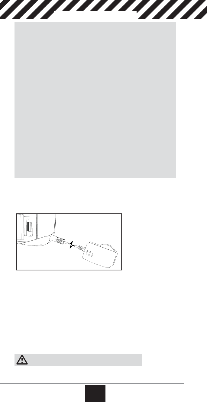
Charging Your Transmitter
The DX18QQ has an internal charger designed to charge the included 2-cell
LiPo battery at a charge rate of 200mAh. The charge port on the right side of the
transmitter is not polarity-dependent.
NOTICE: Never connect an external battery charger to your DX18QQ transmitter.
If you wish to charge the LiPo battery using a LiPo charger, you must remove the
battery from the transmitter before charging.
The fi rst time you charge the transmitter battery, the charge time may be 12–15
hours. Always charge the transmitter on a heat-resistant surface.
1. Power off your transmitter.
2. Connect the power supply connector to the transmitter charge port.
3. Connect the power supply to a power outlet using the appropriate adapter.
4. The blue LED on the front of the transmitter turns on during charging and
turns off when the battery is fully charged.
5. Disconnect the transmitter from the power supply once charging is complete
and disconnect the power supply from the power outlet.
CAUTION: Never leave a charging battery unattended.
8
EN
SPEKTRUM DX18QQ
Page 9

LED indicators
The blue LED indicates the transmitter battery is charging. The orange LED indicates the transmitter is powered on and there is radio transmission.
Battery Alarm
The System Settings Screen allows you to change the battery type and low alarm
settings. See “System Settings” for more information.
• An alarm will sound when the battery reaches the low voltage limit
(4.3V for NiMH, 6.4V for LiPo).
CAUTION: Never change the low voltage limit for LiPo batteries from
6.4V. Doing so could over-discharge the battery and damage both battery
and transmitter.
www.spektrumrc.com
EN
9
Page 10
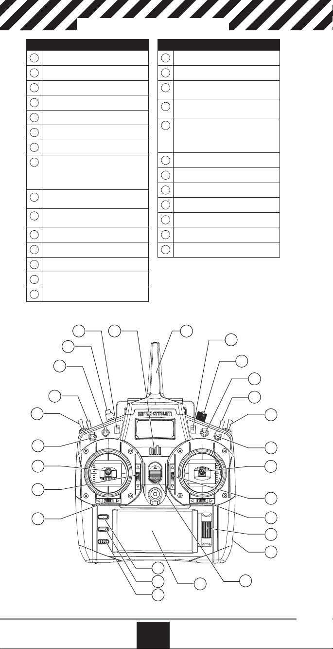
Transmitter Functions
Function
Antenna 1
1
RIght Trim
2
Right Knob
3
Switch E
4
Switch H
5
Switch G
6
Switch F
7
Throttle/Aileron Stick (Mode 1)
8
Elevator/Aileron Stick (Mode 2)
Throttle/Rudder Stick (Mode 3)
Elevator/Rudder Stick (Mode 4)
Elevator Trim (Mode 2, 4)
9
Throttle Trim (Mode 1, 3)
Aileron Trim (Mode 1,2)
10
Rudder Trim (Mode 3,4)
Roller
11
Charge Port
12
On/Off Switch
13
LCD
14
Clear Button
15
Function
Back Button
16
Speaker Grill
17
Rudder Trim (Mode 1,2)
18
Aileron Trim (Mode 3,4)
Elevator Trim (Mode 1,3)
19
Throttle Trim (Mode 2,4)
Elevator/Rudder Stick (Mode 1)
20
Throttle/Rudder Stick (Mode 2)
Elevator/Aileron Stick (Mode 3)
Throttle/AileronStick (Mode 4)
Switch C
21
Switch B
22
Switch A
23
Switch D
24
Bind/Switch I
25
Left Trim
26
LED
27
The transmitter comes with a thin, clear
plastic fi lm applied to some front panels for
protection during shipping. Humidity and
use may cause this fi lm to come off. Carefully remove this fi lm as desired.
22
21
20
19
18
24
23
26 27
25
15
16
17
1
2
3
4
5
6
7
8
9
10
11
12
14
13
10
EN
SPEKTRUM DX18QQ
Page 11
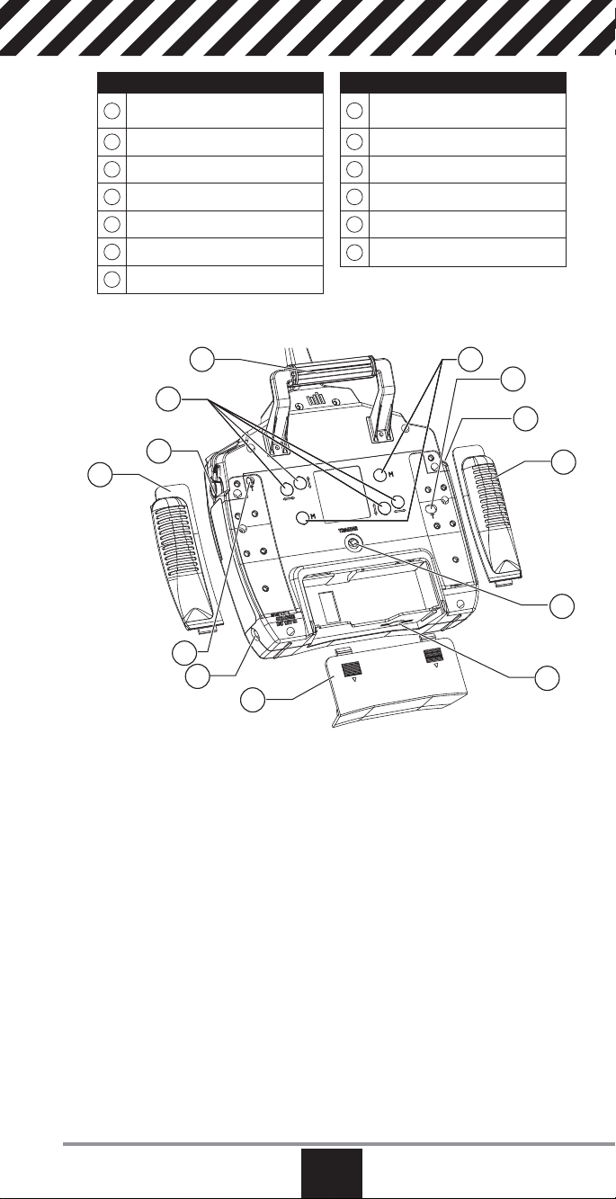
Throttle Spring Tension
1
Adjustment (Mode 2,4)
2
Left Lever
3
Left Rear Grip
4
Trainer Port
5
SD Card
6
Battery Cover
7
Charge Port
Function
Function
Throttle Spring Tension
8
Adjustment (Mode 1,3)
9
Right Rear Grip
10
Right Lever
11
Gimbal Stick Tension Adjustment
12
Handle/Antenna 2
13
Mode Change
12
13
1
11
2
10
9
3
4
8
7
5
6
www.spektrumrc.com
EN
11
Page 12
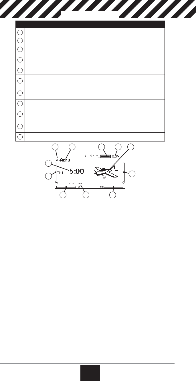
Main Screen
Function
Model Memory
A
B
Model Name
C
Transmitter Battery Charge Level
Digital Battery Voltage (an alarm sounds and the screen fl ashes when battery
D
charge gets down to 4.3V when using an NiMH battery or 6.4V for a LiPo battery.)
E
Model Type
Elevator Trim (Modes 2 and 4)
F
Throttle Trim (Modes 1 and 3)
Aileron Trim (Modes 1 and 2)
G
Rudder Trim (Modes 3 and 4)
H
Model Memory Timer
Rudder Trim (Modes 1 and 2)
I
Aileron Trim (Modes 3 and 4)
Throttle Trim (Mode 2 and 4)
J
Elevator Trim (Mode 1 and 3)
K
Timer
Also displays R Trim values when
the Right Trim button is pressed
Also displays L Trim values when
the Left Trim button is pressed
BA
K
J
I H G
C
ED
F
12
EN
SPEKTRUM DX18QQ
Page 13
Navigation
• Turn the scroll wheel to move through the screen content or change programming values. Press the scroll wheel to make a selection.
• Use the Back
button to go to
the previous
screen
(for example,
to go from the
Mixing Screen
to the Function List).
• Use the
Clear button
to return a
selected value on a screen to the default setting.
• Direct Model Access enables you to access the Model Select screen without
powering off the transmitter. Anytime the transmitter power is on, press the
Clear and Back buttons to access the Model Select screen.
• Press and hold the roller while powering on the transmitter to show the
System Setup list. No radio transmission occurs when a System Setup screen
is displayed, preventing accidental damage to linkages and servos during
changes to programming.
• At the main screen you can roll the roller to view the servo monitor.
• The Main Screen appears when you power on the transmitter. Press the scroll
wheel once to display the Function List.
• When you want to change a value in a screen for a particular control position,
move the control to the desired position to highlight the value you want to
change, such as 0/1/2, up/down or left/right.
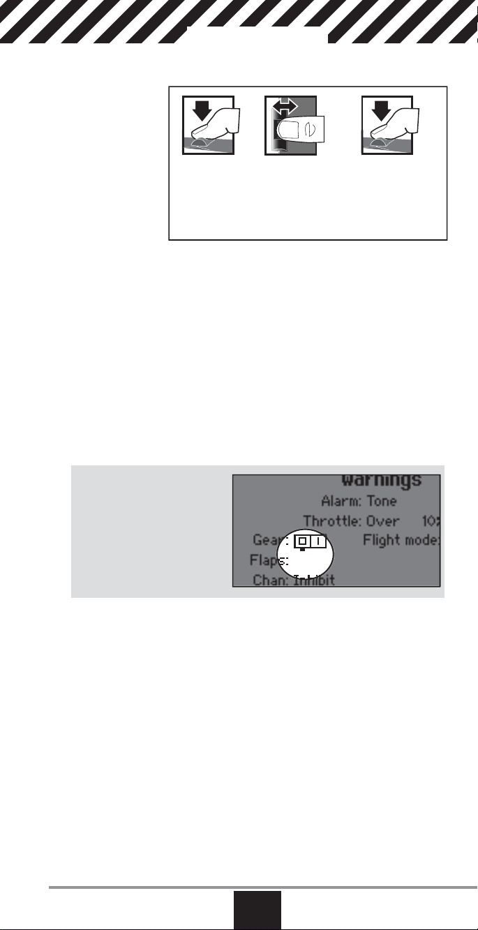
Enter, Choose
or Exit
Turn HoldPress
Move between
options or change
value in an option
Hold for 3
seconds and
release to move to
the Main Screen
Tip: The tick mark below shows
the current switch position.
Rolling and clicking the roller
turns the selected box black,
indicating that the value or condition will act on that position.
www.spektrumrc.com
EN
13
Page 14
Binding
Binding is the process of programming the receiver to recognize the
GUID (Globally Unique Identifi er) code of a single specifi c transmitter. The DX18QQ
and AR12120 are pre-bound at the factory. You will need to rebind after the model programming is initially set up to fully program the model’s failsafe positions.
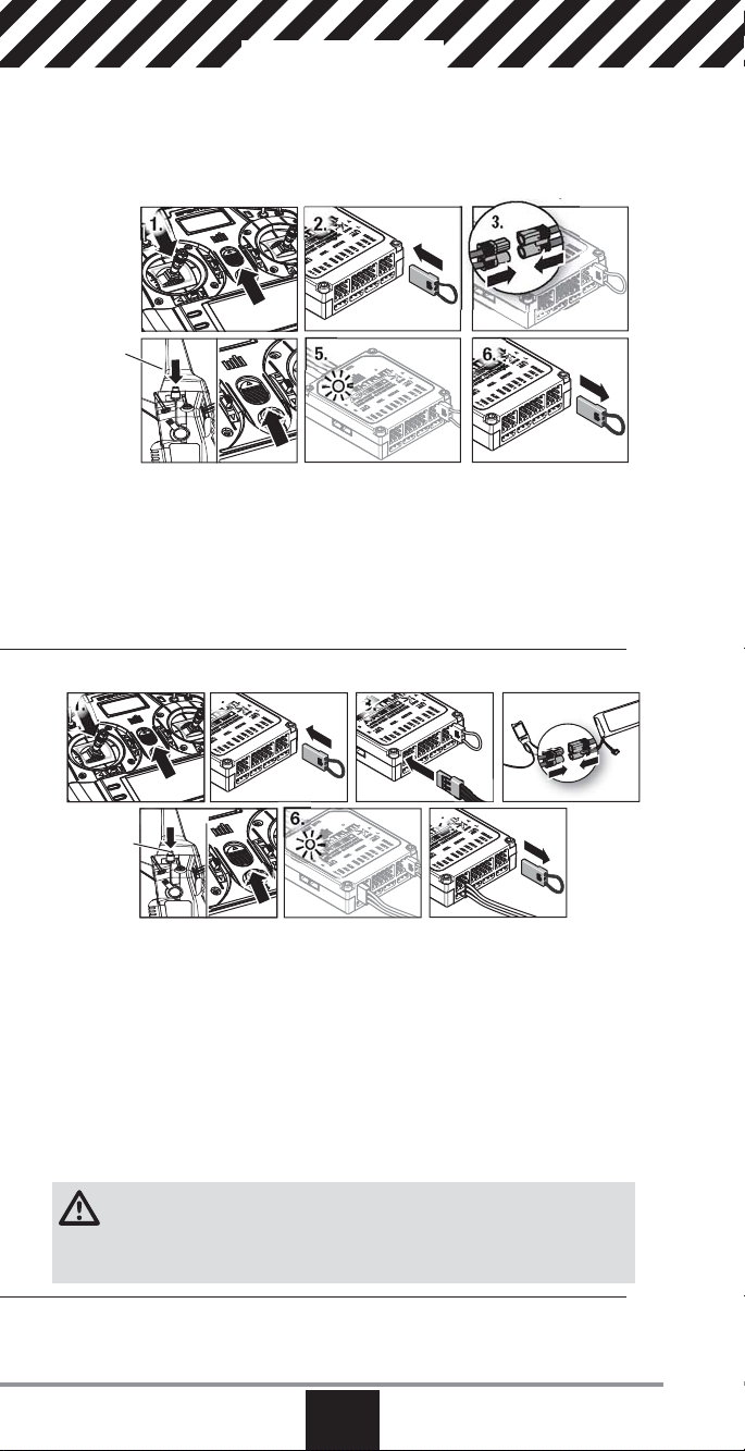
Binding Using the Receiver and Receiver Battery (mode 2 shown)
1. 2.
Hold button
while
powering
on
4. 5. 6.
1. Move the throttle stick to the lowest position and power off the transmitter.
2. Insert the bind plug into the BIND/DATA port on the receiver.
3. Connect a fully charged receiver pack to any open port on the receiver. The
orange LED on the receiver rapidly fl ashes when the receiver is in bind mode.
4. Press and hold the transmitter bind button while powering on the transmitter.
5. Release the Bind button when the transmitter screen displays “Binding”. Binding is complete when the orange transmitter and receiver LEDs turn solid.
6. Power off the receiver and remove the bind plug.
Binding Using the Receiver and ESC (mode 2 shown)
1.
2.
3.
3.
4.
5. 6.
Hold button
while
powering
on
7.
1. Lower the throttle to the lowest position and make sure the transmitter
is powered off.
2. Insert the bind plug into the BIND/DATA port.
3. Insert the ESC plug into the THRO port.
4. Connect the battery to the ESC and turn on the ESC switch, if available. The
receiver’s LED will rapidly fl ash when the receiver is ready to bind.
5. While pressing the Bind button, power on the transmitter.
6. Release the Bind button after the receiver has stopped fl ashing rapidly. Once
the receiver’s LED turns solid, the receiver is bound to the transmitter. The
screen also provides binding information.
7. Remove the bind plug from the receiver.
CAUTION: When using the DX18QQ with parkfl yer receivers, only use
receivers in parkfl yer-type aircraft (small electric airplanes or mini and micro helicopters). Installing parkfl yer receivers in larger aircraft could cause signal
blocking and loss of connection.
14
EN
SPEKTRUM DX18QQ
Page 15

Programming Failsafe Positions
You establish failsafe positions when you bind your transmitter and receiver. If the radio
signal connection is lost between the transmitter and receiver, the receiver immediately
moves the aircraft control surfaces to the failsafe positions. The Spektrum AR12120
receiver has three failsafes programming options: SmartSafe, Hold Last Command,
and Preset.
If you assign the receiver THRO channel to a transmitter channel other than throttle, we
recommend using Preset failsafe with the throttle in the low position.
NOTICE: Failsafe features vary according to receiver. Always consult the receiver
instruction manual for failsafe features.
Before fl ight, ALWAYS confi rm the failsafe functions as you would expect.
SmartSafeTM Failsafe
SmartSafe failsafe is a technology that only acts on the throttle channel and offers
the following benefi ts:
• Prevents electric motors from operating when the receiver power is on and the
transmitter power is off.
• Prevents the speed controller from arming until the throttle is moved to the low
throttle position.
• Powers off an electric motor and reduces gas/glow engines to idle if signal is lost.
To Program SmartSafe, move the throttle to the low or off position before putting the
transmitter into bind mode.
To Test the SmartSafe failsafe
1. Power the transmitter and receiver on.
2. Power off the transmitter. The throttle should immediately move to the failsafe
position.
CAUTION: Make sure the aircraft is fully restrained on the ground. If the
failsafe is not set correctly, your aircraft might advance to mid or full throttle.
Hold Last Command
The Hold Last Command failsafe maintains the last command on all channels except
throttle. If the radio signal is lost, the aircraft maintains the commanded heading until
the receiver regains signal.
To program Hold Last Command, follow the provided binding instructions in this
instruction manual.
To Test Hold Last Command
1. Power on the transmitter and receiver.
2. Move one of the control sticks to the desired Hold Last Command position and
hold the input.
3. While holding the control input (for example, a small amount of rudder) power off
the transmitter. The rudder should maintain the input command.
CAUTION: Make sure the aircraft is fully restrained on the ground. If the
failsafe is not set correctly, the aircraft throttle might advance to mid or full
throttle.
Preset Failsafe
The Preset failsafe moves all channels to their programmed failsafe positions.
We recommend using Preset failsafe to deploy spoilers on sailplanes to prevent a
fl yaway if the radio signal is lost.
To program Preset failsafe:
1. Insert the bind plug in the bind port on the receiver and power on the receiver.
2. Remove the bind plug when the orange LED on the main receiver and all attached
remote receivers fl ash rapidly. The orange receiver LEDs will continue fl ashing.
3. Move the transmitter control sticks and switches to the desired Preset failsafe
position. Power the transmitter on.
4. Failsafe programming is complete when the orange LEDs on the transmitter and
all receivers turn solid.
CAUTION: Make sure the aircraft is fully restrained on the ground. If the
failsafe is not set correctly, the aircraft throttle might advance to mid or full
throttle.
www.spektrumrc.com
EN
15
Page 16
X-PlusTM 8
The X-Plus 8 module is designed to allow expansion of up to 8 servos for noncontrol surface functions such as bomb drops, lights, winches, retractable landing
gear, and many more. The X-Plus 8 is compatible with Spektrum™ X-Plus transmitters and receivers. The X-Plus 8 module offers the option to power the connected servos via dual auxiliary battery ports with separate batteries and switch
harnesses (sold separately) independent of the receiver. The X-Plus 8 module can
also be powered inclusive of the receiver by using the included jumper through
either of the dual BATT/JMPR ports.
Features:
• 8-channel expansion
• Dual battery ports
• Included Jumper offers option of using receiver power
• Allows fi ne tuning of 8 servos on non-critical controls (bomb drops, lights,
winches, gear, etc.)
Applications
Scale modelers with complex aircraft, ships, or surface applications will enjoy the
easy programming and functions of the X-Plus 8 module using X-Plus compatible
transmitters AirWare™ software. Modelers will be able to select 2 position,
3 position or potentiometer adjustment through their transmitter. After selecting
the specifi c switch or port, AirWare software will allow the individual servo adjustment of each X-Plus channel‘s travel adjust, sub trim, reversing, and speed.
Specifi cations
Type: X-Plus Module
Channels: 8
Dimensions: 0.91x 1.61 x 0.79 in
Weight: .42 oz (11.9 g)
Voltage Range: 3.5 to 9.6V
Resolution: 512
Compatibility: All X-Plus transmitters
(23 x 41 x 20mm)
and receivers
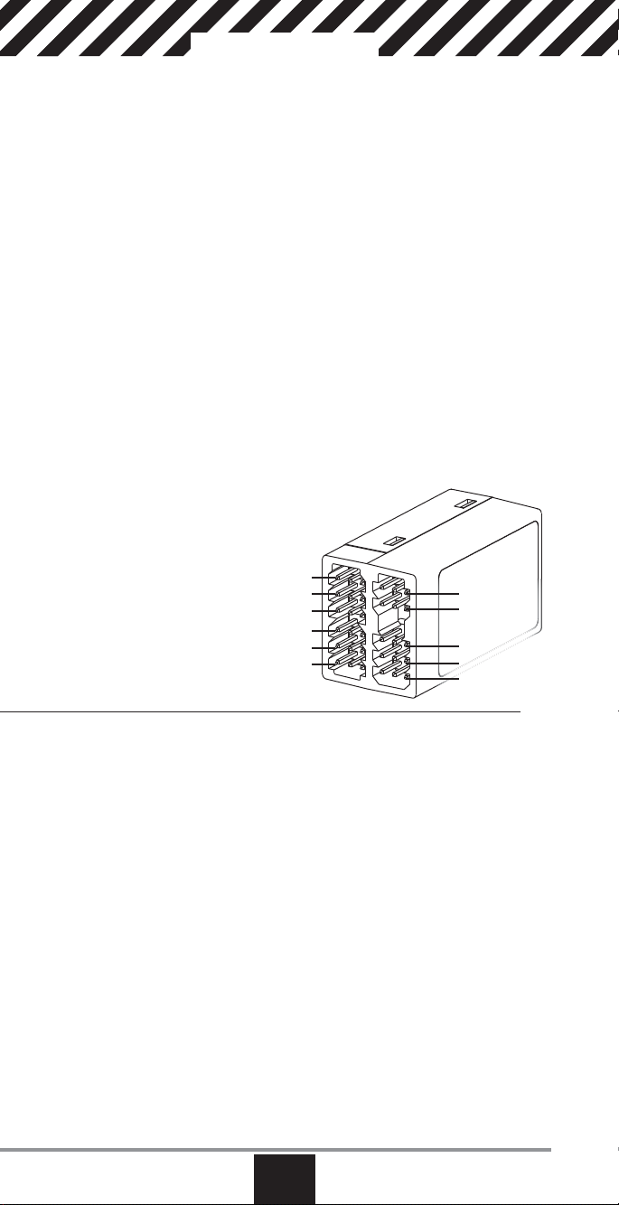
X+1
X+2
X+3
X+4
X+5
X+6
X+7
X+8
BATT/JMPR
BATT/JMPR
SRXL
Installation
In gas and glow aircraft, install the X-Plus 8 module by wrapping it in protective
foam and fastening it in place using rubber bands or a hook and loop strap. In
electric airplanes or helicopters, you can use thick double-sided foam tape to
fasten the module in place.
When using an X-Plus receiver and module, it is recommended that the X-Plus 8
module be mounted as near to the receiver as possible. When using the jumper
lead to power the module, mounting the X-Plus 8 module near the receiver
system will minimize the current loss from the receiver. Servo extensions can be
used with each servo, but we recommend using heavy 22 gauge wire with goldplated connectors.
A power jumper plug must be installed in one of the BATT/JMPR ports of the
module if the module is powered from the receiver through the SRXL port.
Always remove the power jumper when an auxiliary battery or auxiliary batteries
are used. When the auxiliary battery option is used, the X-Plus 8 module can be
mounted as far away from the receiver as needed to be near connected servos.
16
EN
SPEKTRUM DX18QQ
Page 17
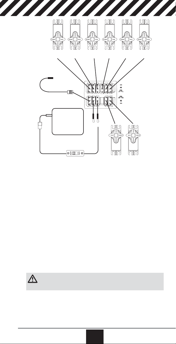
X+6 Servo
To SRXL Port
X+5 Servo
Auxiliary Battery Pack
(optional)
On/Off Switch Harness (optional)
X+4 Servo X+3 Servo X+2 Servo X+1 Servo
Jumper
X+8 Servo X+9 Servo
Power System Requirements
Inadequate power systems that do not provide the necessary minimum voltage to
the receiver during fl ight are the number one cause of in-fl ight failures. Some of
the power system components that affect the ability to properly deliver adequate
power include:
• Receiver battery pack (number of cells, capacity, cell type, state of charge)
• The ESC’s capability to deliver current to the receiver in electric aircraft
• The switch harness, battery leads, servo leads, regulators, etc.
The X-Plus 8 module has a minimum operational voltage of 3.5 volts; it is highly
recommended that the power system be tested per the guidelines below.
Recommended Power System Test Guidelines
If a questionable power system is being used (e.g., a small or old battery, an ESC
that may not have a BEC that will support high-current draw, etc.), perform the
following test with a voltmeter. The Hangar 9
®
Digital Servo & Rx Current Meter
(HAN172) or the Spektrum Flight Log (SPM9540) work well for this test.
Plug the voltmeter into an open channel port in the receiver and, with the system
on, load the control surfaces (apply pressure with your hand) while monitoring the
voltage at the receiver. The voltage should remain above 4.8 volts even when all
servos are heavily loaded.
CAUTION: When charging Ni-MH batteries, make sure the battery fully
charges. Ni-MH batteries charged with peak detection fast chargers have
a tendency to false peak (i.e. not fully charge), which could lead to a crash.
www.spektrumrc.com
EN
17
Page 18
X-Plus Channels and Failsafe
Failsafe is not supported for servos connected to the X-Plus Module. We recommend that no failsafe should be expected or attempted for a servo connected
through the X-Plus Module. However, servos connected to the X-Plus Module will
hold last command in the event of a failsafe condition.
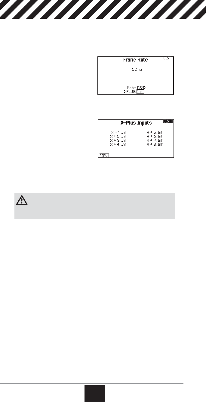
To Activate X-Plus
1. Open the Frame Rate Menu in
System Setup.
2. Scrolll to X-Plus and press the
scroll wheel to activate. The X-Plus
Inputs screen is now active in the
Channel Assign menu.
AUX6 and AUX7 channels are available on 12-channel receivers when X-Plus is
active. AUX6 and AUX7 are 2048 resolution and 22ms frame rate (12-channel
receivers only).
Channels X+1 and X+2 are duplicate
channels of channels 11 and 12 on a
12-channel receiver with X-Plus active.
If channels 11 and 12 require any
adjustment for travel adjust, servo
reversing, sub trim or any other function,
adjust channels X+1 and X+2.
Note that channels 11 and 12 will
also show on the X-Plus monitor as
channels X+1 and X+2.
If you select 11ms frame rate before you activate X-Plus, the transmitter reverts
to 22ms frame rate when X-Plus is active.
CAUTION:
X-Plus Module. The X-Plus channels are intended to be used for auxiliary
functions only. X-Plus channels have a resolution of 512 and variable latency from
22ms to about 88ms. When X-Plus is active, the fi rst 10 channels default to 22ms.
Refer to community.spektrumrc.com for more information about X-Plus options.
Do NOT connect throttle or any primary control surface to the
from Channel Assign menu
18
EN
SPEKTRUM DX18QQ
Page 19
SD Card
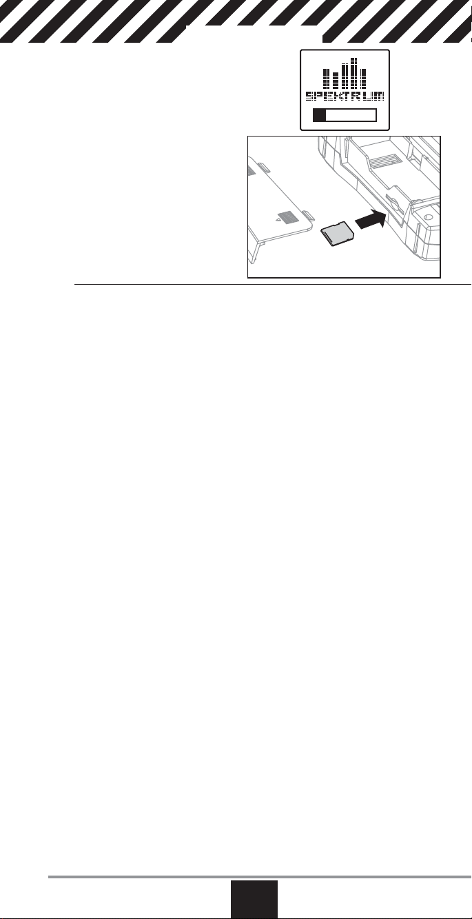
Installing the SD Card
The included SD Card enables you to:
• Import (copy) models from another
DX18QQ transmitter
• Export (transfer) models to another
DX18QQ transmitter
• Update AirWare™ software in the
transmitter
To install the SD Card:
1. Power off the transmitter.
2. Remove the battery door.
3. Press the SD Card into the card
slot with the card label
facing upward.
4. Install the battery door.
Exporting the Transmitter Serial Number to the SD Card
Exporting the transmitter serial number to the SD Card allows you to
copy and paste the serial number into the registration screen at
community.spektrumrc.com.
To export the serial number:
1. Press and hold the scroll wheel while powering the
transmitter on until the System Setup list appears.
2. Scroll to the System Settings menu. Press the scroll wheel once
to open the menu.
3. Select NEXT on the System Settings and Extra Settings screens.
4. When the Serial Number screen appears, select EXPORT.
5. Power off the transmitter and remove the SD Card from the transmitter.
6. Insert the SD Card in your computer and open the .txt fi le on the card.
7. Copy and Paste the serial number into the Registration screen on the
Spektrum Community site (community.spektrumrc.com).
www.spektrumrc.com
EN
19
Page 20
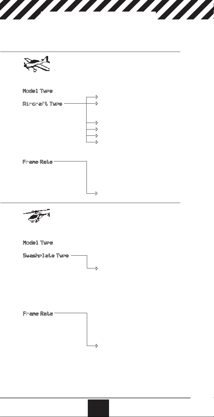
Model Type Programming Guide
Menu options show up on model type selection. These menu options vary
between Model Types (Airplane Helicopter and Sailplane), but are identical for all
models in that type. Subsequent aircraft type (Aircraft, Swashplate or Sailplane)
selections make other menu options appear.
System Setup List:
Model Select
Model Type
Model Name
Aircraft Type
F-Mode Setup
Channel Assign
Trim Setup
Model Copy
Model Reset
Warnings
Telemetry
Preflight Setup
Frame Rate
Bind
Trainer
Analog Switch Setup
System Settings
Transfer SD Card
System Setup List:
Model Select
Model Type
Model Name
Swashplate Type
F-Mode Setup
Channel Assign
Trim Setup
Model Copy
Model Reset
Warnings
Telemetry
Preflight Setup
Frame Rate
Bind
Trainer
Analog Switch Setup
System Settings
Transfer SD Card
Function List:
Servo Setup
D/R and Expo
Differential
V-Tail Differential
Throttle Cut
Throttle Curve
Gyro1
Gyro2
Pitch Curve
Flap System
Mixing
Sequencer
Range Test
Timer
Telemetry
System Setup
Monitor
XPlus Monitor
Function List:
Servo Setup
D/R and Expo
Throttle Cut
Throttle Curve
Pitch Curve
Swashplate
Gyro
Governor
Tail Curve
Mixing
Sequencer
Range Test
Timer
Telemetry
Frame Rate
System Setup
Monitor
XPlus Monitor
20
EN
SPEKTRUM DX18QQ
Page 21
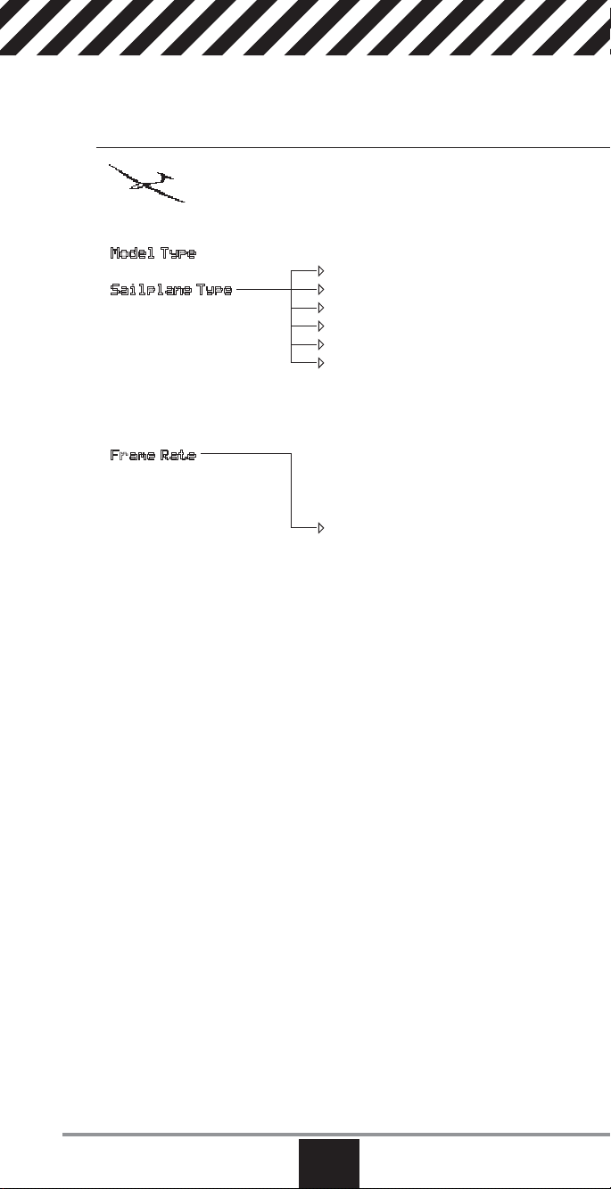
System Setup List:
Model Select
Model Type
Model Name
Sailplane Type
F-Mode Setup
Channel Assign
Trim Setup
Model Copy
Model Reset
Warnings
Telemetry
Preflight Setup
Frame Rate
Bind
Trainer
Analog Switch Setup
System Settings
Transfer SD Card
Function List:
Servo Setup
D/R and Expo
Differential
V-Tail Differential
Throttle Cut
Motor Curve
Camber Presets
Camber System
Mixing
Sequencer
Range Test
Timer
Telemetry
Frame Rate
System Setup
Monitor
XPlus Monitor
www.spektrumrc.com
EN
21
Page 22
Common System Setup FunctIons
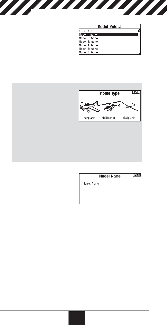
Model Select
Model Select enables you to access any
of the 50 internal model memory
locations in the Model Select list.
1. Scroll to the desired model memory
in the Model Select list.
2. When the desired model memory is
highlighted, press the scroll wheel
once to select the model. The transmitter returns to the System Setup List.
Direct Model Access
Press the Clear and Back buttons from the Main Screen or a telemetry screen to
access Model Select.
Model Type
Select from Airplane, Helicopter
or Sailplane model types.
IMPORTANT: When you select a new
model type, you will delete any programming data in the current model
memory. Always confi rm the desired
model memory before changing model
types. It will be necessary to re-bind after resetting the model type.
To change the model type:
1. Scroll to the desired model type and press the scroll wheel. The Confi rm
Model Type screen appears.
2. Select Yes and press the scroll wheel to confi rm the model type. All data will
be reset. Selecting No will exit the Confi rm Model Type screen and return to
the Model Type screen.
Model Name
Model Name enables you to assign
a custom name to the current model
memory. Model names can include up
to 20 characters including spaces.
To add letters to a Model Name:
1. Scroll to the desired letter position
and press the scroll wheel once.
A fl ashing box appears.
2. Scroll left or right until the desired character appears. Press the scroll wheel
once to save the character.
3. Scroll to the next desired letter position. Repeat Step 1 and 2 until the Model
Name is complete.
4. Select BACK to return to the System Setup list.
22
EN
SPEKTRUM DX18QQ
Page 23
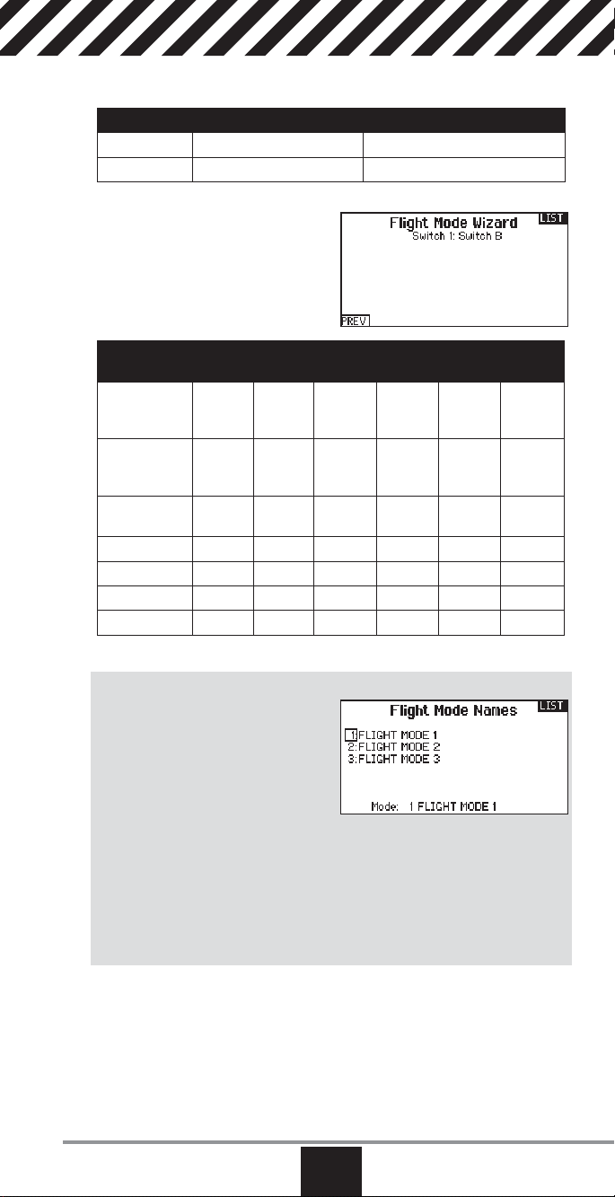
F-Mode Setup
Use the Flight Mode Setup menu to assign switches to fl ight modes.
Mode Number of Switches Number of Flight Modes
Aircraft Up to 3 5
Heli 3 (including Throttle Hold) 5 (including Throttle Hold)
Sailplane Flight Mode Setup
You can assign up to ten fl ight modes
using any combination of up to three
switches. You can also assign a priority
switch. When the priority switch position
is active, only the current fl ight
mode is active, regardless of other
switch positions.
Number of
Flight Modes
Switch 1
(number of
positions)
Switch 2
(number of
positions)
Flight Mode
1
2 Cruise Cruise Cruise Cruise Cruise Cruise
3 Land Land Land
4 Thermal Thermal Thermal Thermal
5 Speed Speed
*Must be set up in a 4/5 fl ight mode.
2 3 3* 4 4 5
2P 3P 2P 2P 3P 3P
2P 3P 2P 3P
Launch Launch Launch Launch Launch Launch
Flight Mode Name Setup
Enables you to assign custom names to
the Flight Mode positions. Flight Mode
names can include up to 20 characters
including spaces.
To change the Flight Mode name:
1. Scroll to the Flight Mode name you
wish to change and press the scroll
wheel.
2. Scroll to the character position you wish to change and press the scroll wheel
once. A fl ashing box appears.
3. Scroll left or right until the desired character appears. Press the scroll wheel
once to save the character.
4. Repeat Steps 2 and 3 until the Model Name is complete.
5. Select BACK to return to the Flight Mode Names list.
Aircraft and Sailplane Flight Mode Table
You can assign the available fl ight modes (up to 5 for Air, up to 10 for Sail) to
each of the switch positions (up to 3 switches can be used). Press NEXT from
the Flight Mode Name page to access the fl ight mode table assignment page
when Custom fl ight mode has been selected in the Flight Mode Setup page. The
combination of up to 3 switches can be used to access all of the fl ight modes
available.
www.spektrumrc.com
EN
23
Page 24

Channel Assignment
The Channel Assignment function allows
you to reassign almost any receiver
channel to a different transmitter channel. For example, the receiver gear
channel could be re-assigned to the
transmitter throttle channel.
When X-Plus is active in the transmitter,
the DX18QQ operates channels 11 and 12 (AUX 6 and AUX 7) on a 12-channel
receiver. Channels 11 and 12 will have 22ms frame rate and 2048 resolution.
X-Plus allows for up to 8 additional channels over the 10 primary channels.
1. Scroll to the receiver channel you wish to change.
2. Press the scroll wheel once and scroll left or right to change the receiver input
selection.
3. Press the scroll wheel a second time to save the selection.
Channel Input Confi guration
The Channel Input Confi guration screen
enables you to assign a transmitter
channel to a different control stick
or switch.
1. Select NEXT on the RX Port Assignments screen to access the Channel
Input Confi guration screen.
2. Scroll to the transmitter channel you wish to re-assign and press the scroll
wheel. The box around the current input selection fl ashes.
3. Scroll left or right to select the desired control stick or switch.
4. Press the scroll wheel to save the selection.
X-Plus Input Confi guration
The X-Plus Input Confi guration screen
enables you to assign any X-Plus
channel to any transmitter input.
1. Select NEXT on the Channel Input
Confi g screen to access the X-Plus
Input Confi g screen.
2. Scroll to the X-Plus channel you
wish to change.
3. Press the scroll wheel once and scroll left or right to change the X-Plus Input
for that X-Plus channel.
24
EN
SPEKTRUM DX18QQ
Page 25

Trim Setup
Use the Trim Setup screen to change
the size of the trim step and the trim
type.
Trim Step
Adjusting the trim step value determines
how many “clicks” of trim you input
each time you press the trim button.
Changing the trim step value to 0 disables the trim for the channel.
To change the trim step value:
1. Scroll to the trim step channel you wish to change.
2. Select the trim step value and scroll left or right to change the value.
3. Press the scroll wheel to save the selection.
Trim Type
The two Trim Type options are Common and F Mode.
Common trim type maintains the same trim values for all fl ight modes.
F Mode trim type enables you to save trim values for individual fl ight modes if
you fi nd, for example, the aircraft requires aileron trim in Flight Mode 1 but not in
Flight Mode 2.
Trim Assignment
In a few instances, you can reassign a trim to a different location.
Aircraft Model Type
Throttle
• Throttle Digital trim button (default)
• Left Analog lever
• Right Analog lever
Throttle trim type
• Common
• Flight Mode
• 3-Pos
Tip: With throttle trim set to 3-Pos, the throttle trim will function as a 3-position
throttle trim where the throttle trim can be set to low, middle, and high. This can
be helpful for turbine set up.
Helicopter Model Type
Throttle and Pitch Hover Trim — Used to trim the throttle and pitch setting for
precision hovering. This does not affect normal throttle trim operation.
• Right Knob
• Left Analog Lever
• Right Analog Lever
• L Trim
• R Trim
Active Gyro and Governor Trim—Used to trim the gyro and governor settings in
fl ight.
• L Trim
• R Trim.
Trim Location
Normal and Cross trim types are available. Normal trims align with the control
stick; for example, the throttle trim is next to the throttle stick.
Cross trims reverse the position of the trims; for example, the throttle trim is next
to the elevator stick and vice versa.
To change the Trim Position from Normal to Crossed, select Normal at the bottom
of the Trim Setup screen and press the scroll wheel.
IMPORTANT: Crossed trims will cross both sets of trims for both gimbals.
www.spektrumrc.com
EN
25
Page 26

Model Copy
The Model Copy menu enables you to
duplicate model programming from one
Model List location to another.
Use Model Copy to:
• Sort the models in the Model List by
brand, model type or power source
• Save a default model copy before
experimenting with programming values
• Expedite programming for a model using a similar programming setup.
IMPORTANT: Copying a model program from one model memory to another will
erase any programming in the “To” model memory.
To copy model programming:
1. Make sure the model program you wish to copy is active. If the desired
model program is not active, select Cancel and change the active model in
the Model Select menu.
2. Select the model memory next to “To” and scroll to the desired model
memory. Press the scroll wheel once to save the selection.
3. Select Copy and the Confi rm Copy screen appears.
4. Select Copy to confi rm. Selecting Cancel will return to the Model Copy screen.
You cannot use the Model Copy screen to copy model programming to an SD
Card. To copy model programming to the SD Card, please see “Transfer SD Card”.
Model Reset
Use the Model Reset menu to delete all
model programming in the active model
memory. Reset returns all model settings to the default settings and erases
all programming in the selected model.
After a model reset, it is necessary to
re-bind.
Warnings
The Warnings menu enables you to
program a tone or vibration alert during
power on of the transmitter for any
selected switch or channel position.
The alarm activates and an alert message appears on the screen if a specifi c
switch or control stick is in an unsafe
position when you power the transmitter on.
Return the switch or control stick to the safe position to silence the alarm.
For safety reasons, the default throttle alarm activates if the throttle position is
above 10%.
26
EN
SPEKTRUM DX18QQ
Page 27

Telemetry
Installing the optional telemetry module
and sensors enables the display of
aircraft performance data on the
transmitter screen. You can also enable
Data Logging to save a telemetry fi le on
the SD Card and view the data in the
Spektrum STi
Telemetry Settings
Display
Telemetry display options include:
Tele: When you press the scroll wheel, the Telemetry screens appear and the
Main: Telemetry alerts appear on the Main screen, but all Telemetry screens
Roller (Default): Allows you to toggle between the Telemetry screens and the
Auto: The Telemetry screen automatically appears as soon as the transmitter
Units
Scroll to Units and press the scroll wheel to change between US and Metric.
File Settings
This is used to select the data logging settings.
File Name
1. Select File Name to assign a custom fi le name.
2. The File Name screen appears, allowing you to name the fi le as you would for
3. Press BACK to save the name.
Start
1. Select Start to assign a specifi c switch position or stick
2. Press the scroll wheel once to save the selection.
Enabled
When Enabled is set to NO, Data Logging is turned off.
Select YES to save Telemetry data to the SD Card. The SD Card must be installed
in the transmitter to select YES.
is not an error, but there will be a momentary loss of radio signal when exiting the
Telemetry screen. Do NOT access the Telemetry menu during fl ight.
TM
mobile application.
Main Screen is disabled.
are disabled.
main screen by pressing the scroll wheel.
receives data from the telemetry module.
a Model Name or Flight Mode Name. The fi le name can include a maximum
of 8 characters.
position that activates Data Logging.
CAUTION: If you access the Telemetry menu from the Function List, you
may see a Frame Loss appear when you exit the menu. The Frame Loss
www.spektrumrc.com
EN
27
Page 28

Prefl ight Setup
The Prefl ight Setup menu option
enables you to program a pre-fl ight
checklist that appears each time you
power on the transmitter or when you
select a new model memory. Each item
on the list must be confi rmed before you
can access the Main Screen.
Frame Rate
The Frame Rate menu enables you
to change the frame rate, modulation
mode and activate X-Plus.
Select the option you wish to change
and press the scroll wheel.
Frame Rate
You must use digital servos if you select 11ms frame rate. Analog and digital
servos can be used with a 22ms frame rate. However, if you select a 11ms frame
rate, you must use digital servos.
Modulation Mode
We recommend using DSMX (default) modulation mode. When DSMX is active,
the transmitter operates in DSMX with DSMX receivers and DSM2 with DSM2
receivers. The transmitter automatically detects DSM2 or DSMX during binding
and changes the mode accordingly to match the receiver type you are using.
If you select DSM2, the transmitter operates in DSM2 regardless of whether it is
bound to a DSM2 or DSMX receiver.
X-Plus Activation
Activate X-Plus channels in the Frame Rate Screen. You can set X-Plus to INH
(inhibit) or Act (activate).
NOTICE: While DSMX allows you to use more than 40 transmitters simultane-
ously, do not use more than 40 transmitters simultaneously when using a DSM2
receiver or a transmitter in DSM2 mode.
CAUTION: Do NOT connect the throttle or any primary control surface to the
X-Plus module. The X-Plus channels are intended to be used for auxiliary
functions only. X-Plus channels have a resolution of 512 and variable latency from
22ms to about 88ms. When X-Plus is active, the fi rst 10 channels default to 22ms.
Bind
The Bind menu enables you to bind a
transmitter and receiver without powering off the transmitter. This menu is
helpful if you are programming a model
and need to bind the receiver for failsafe
positions.
See “Programming Failsafe Positions”
for more information.
28
EN
SPEKTRUM DX18QQ
Page 29
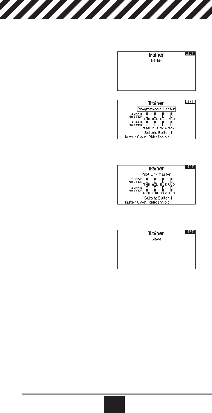
Trainer
The DX18QQ features a programmable trainer function with 4
trainer modes. The transmitter assigns the trainer function to Switch I. The 4
trainer modes include:
Inhibit
In Inhibit, the slave transmitter must
have the same programming as the
master transmitter (e.g., servo reversing, travel adjust, sub-trim, trims).
Programmable
Programmable mode enables you to
program the master transmitter to
transfer any or all individual channels
when you activate the trainer switch.
This mode is ideal for beginners learning to control individual channels while
the master transmitter maintains control of all other channels.
The slave transmitter should be in Pilot Link Slave mode, if available. It is not
necessary to have model programming in the slave transmitter.
Pilot Link Master
When Pilot Link Master is active, the
slave transmitter controls the primary
stick functions (Throttle, aileron, elevator
and rudder) while the master maintains
control of all other channels and functions (including dual rates and auxillary
switch positions). Pilot Link Master is ideal for complex models, as the master
transmitter maintains control of all secondary functions—for example fi lght
modes, retracts, fl aps and brakes.
Slave
Use Slave mode when using the
DX18QQ as a slave transmitter and Pilot
Link is active in the master transmitter.
DX18QQ Trainer Operation
1. Bind the master transmitter to the model.
2. Connect the trainer cord (SPM6805) to the back of the master transmitter.
3. Make sure the master and slave transmitter battery packs are fully charged.
4. Make sure the slave transmitter is powered off. The slave transmitter receives
power when you connect the trainer cord.
5. Connect the trainer cord to the slave transmitter.
6. The slave transmitter screen displays information but does not send a signal
to the model.
7. Press the trainer button on the master transmitter to transfer model control
from the master to the slave.
8. Release the trainer button and the master transmitter regains control of the
model.
www.spektrumrc.com
EN
29
Page 30

Analog Switch Setup
Allows all sticks and pots to be used as a
kick point to turn on functions like mixes.
To add a kick point:
1. Move the control stick, lever or knob
to the desired kick point position.
2. Scroll to the desired kick point and
press the scroll wheel once to save
the selection.
To delete a kick point, scroll to the desired kick point and press the Clear button.
System Settings
The System Settings menu consists of four screens: System Settings, Extra
Settings, Serial Number and Calibrate. Select NEXT or PREV to move between
screens.
User Name
The User Name fi eld displays your name
in the lower right corner of the main
screen.
To Program a User Name
1. Scroll to User Name and press the
scroll wheel. The User Name screen
appears.
2. Scroll to the desired character position and press the scroll wheel. Scroll
left or right to change the character and press the scroll wheel to save the
selection. The User Name can contain a maximum of 20 characters, including
spaces.
3. Press the Back button to save the User Name and return to the System Settings screen.
Contrast
To adjust the screen contrast:
1. Scroll to Contrast and press the scroll wheel.
2. Scroll left or right to adjust the contrast value. Lower numbers lighten the
contrast, higher numbers darken it.
3. Press the scroll wheel once to save the selection.
Backlight
The Backlight fi eld adjusts the backlight appearance time and brightness. You
have the option to turn the backlight off for models you fl y during the day and turn
the backlight on for night fl ying models.
The backlight time options are:
Off: Appears for a short time when you power on the transmitter.
On: The backlight is always on.
Set Time: The backlight is on for 3, 10, 20, 30, 45 or 60 seconds before
automatically turning off. Press the scroll wheel once to turn the backlight on.
The backlight percentage adjusts the backlight intensity and it is adjustable in
10% increments from 10% (darker) to 100% (brighter).
30
EN
SPEKTRUM DX18QQ
Page 31

Mode
You can change transmitter modes among Modes 1, 2, 3 and 4. This conversion requires both a programming and a mechanical change. Please refer to
Transmitter Mode Conversion on page 61 for directions on making the necessary
mechanical changes. If mechanical changes are required for the mode you need
to change to, complete the mechanical changes fi rst, then follow the instructions
below for the software setting change.
To change the gimbal stick mode:
1. Scroll to Mode and press the scroll wheel.
2. Scroll left or right to change the gimbal stick mode. Press the scroll wheel to
save the selection.
3. Select NEXT in the lower left corner until the Calibration screen appears.
4. Move all transmitter controls to the center position and complete the calibration process before exiting the System Settings menu. See “Calibrating Your
Transmitter” for more information.
Battery Alarm
Battery Alarm enables you to change the transmitter battery type and the alarm
voltage limit. The alarm activates when the battery reaches the low voltage limit.
To change the battery alarm:
1. Scroll to the battery type and press the scroll wheel once to change the type
to LiPo or NiMH.
CAUTION: Never select NiMH when a LiPo battery is installed in the
transmitter. Doing so may over-discharge the LiPo battery and damage the
battery, transmitter or both.
2. Scroll to the battery voltage and press the scroll wheel. Turn the scroll wheel
left or right to change the voltage level. Press the scroll wheel again to save
the selection.
CAUTION: Never adjust the low voltage limit for the LiPo battery pack
below 6.4V. Doing so could over-discharge the battery pack and damage
both battery pack and transmitter.
Selecting a Language
In the Systems Settings screen, rotate the roller to highlight Language, then press
the roller to select the Language function.
Rotate the roller to select the desired Language. When the desired Language is
selected, press the roller to accept that Language. Names you input will not be
affected by language change.
Selecting a Region (EU Version)
The Region fi eld enables you to change the region of operation and power output
for transmitters sold in the European Union.
Region options include:
EU-328 FR-328
If you are using the transmitter in France, you must select
FR-328 to comply with power output regulations in France.
To change the region:
1. Scroll to Region and press the scroll wheel.
2. Scroll left or right to change the region and press the scroll wheel once to
save the selection.
Transmitters sold outside of Europe do not have the option to change the region
from US-247.
www.spektrumrc.com
EN
31
Page 32

Inactive Alarm
An alarm activates if the transmitter sees a period of inactivity for a certain
amount of time. The alarm is helpful in reminding you to power off the transmitter
and avoiding a situation when the transmitter battery completely discharges.
The Inactive Alarm options are:
• Inh (No alarm sounds)
• 5 min
• 10 min (Default)
• 30 min
• 60 min
To change the Inactive alarm time:
1. Scroll to the current alarm time and press the scroll wheel.
2. Scroll left or right to change the alarm time. Press the scroll wheel
to save the selection.
Extra Settings
The Extra Settings screen
enables you to:
• Turn sounds off or on
• Turn vibration off or on
• Change the appearance of the trim
indicators
System Sounds
Scrolling to System Sounds and pressing the scroll wheel turns sounds on (Active)
or off (Inhibit).
Vibrator
Scrolling to Vibrator and pressing the scroll wheel turns vibration alerts on (Active)
or off (Inhibit).
Trim Display
Trim display changes the shape of the trim indicators on the Main Screen. Display
options include:
• Boxed Boxes (Default)– The indicators appear as an outlined box when you adjust
the trim.
• Boxed Arrows– The indicators appear as outlined arrows when you adjust the
trim.
Inhibit removes all trim bars and indicators from the Main Screen.
To change the Trim Display:
1. Scroll to Trim Display and press the scroll wheel once.
2. Scroll left or right to change the Trim Display option. Press the scroll wheel to
save the selection.
32
EN
SPEKTRUM DX18QQ
Page 33

Serial Number
The Serial Number screen displays the
transmitter serial number and AirWare
software version.
Reference the Serial Number screen
any time you need to register your
transmitter or update the AirWare
software from the Spektrum Community
website.
Exporting the Serial Number to the SD Card
You may fi nd it helpful to export the transmitter serial number to a text fi le for your
personal records or when you are registering the transmitter on the Spektrum
Community.
To export the transmitter serial number:
1. Insert an SD Card in the card slot on the transmitter.
2. Scroll to EXPORT and press the scroll wheel. The SD Status screen appears
and should display MY_DX18QQ.xml in the middle of the screen.
3. Press the scroll wheel again to return to the Serial Number screen.
4. Power off the transmitter and remove the SD Card from the transmitter.
5. Install the SD Card in a card reader connected to your computer.
6. Open the MY_DX18QQ.xml fi le from the SD Card location. You can then copy
and paste the serial number into your personal records or to the Spektrum
Community website.
Locating the Transmitter AirWare Software Version
The transmitter AirWare software version appears between PREV and NEXT at
the bottom of the Serial Number screen. Register your DX18QQ to get AirWare
software updates and other news at community.SpektrumRC.com
IMPORTANT: AirWare fi les are specifi c to the transmitter serial number and you
cannot transfer AirWare fi les between transmitters, ie., downloading an AirWare
software update once and attempting to install it on multiple transmitters.
Calibrate
The Calibration screen stores the
potentiometer endpoints for all
proportional controls. It is mandatory to
complete the calibration after changing
the stick mode selection.
Calibrating the Transmitter
1. Carefully move the gimbal sticks in a + shape moving from left to right, then
up and down. Press gently on the gimbals at the stops to achieve an accurate
calibration. Return both gimbal sticks to the center position.
2. Move the Left and Right Side Levers to the top and bottom positions, then
move the side levers to the center position.
IMPORTANT: Only move one side lever at a time during calibration.
3. Move the Knob to the full clockwise and counter-clockwise positions, then
return the Knob to the center position.
4. Select SAVE to store the calibration.
www.spektrumrc.com
EN
33
Page 34

Transfer SD Card
Import Model
To import an individual model fi le
from the SD Card:
1. Save the model fi le to the SD Card.
2. Select the Model List location where
you wish to import the new model
fi le.
3. In the SD Card menu, scroll to Select Option and press the scroll button once.
4. Scroll to Import Model and press the scroll button again to save the selection.
The Select File screen appears.
5. Select the model fi le you wish to import. The Overwrite screen appears.
IMPORTANT: When you select Import, the transmitter leaves the System
Setup List.
6. Select the model that you would like to import the model to.
7. Select Import to confi rm overwriting the current model fi le. The transmitter
activates the new model fi le and the Main Screen appears.
NOTICE: A Prefl ight Checklist may appear prior to the Main Screen if the checklist
was active during the model fi le export. Select MAIN to exit the Prefl ight Checklist.
See “Prefl ight Setup ” for more information.
Import All Models
To import all models from the SD Card:
1. Select Import All Models
2. Confi rm by selecting IMPORT.
NOTICE: This function overwrites the model memories. Ensure that the models
currently in your transmitter are saved on an SD card separate from the
transmitter before performing this function.
You can import a model to any location you want. If you prefer to use Import All,
you can use your PC to rename the SPM fi le. The fi rst two digits (01 to 50) are
the destination model number. Your SD card can only contain 50 models. Save
fi les to folders on the card then remove from the card all unused models. Files are
selected by their position in the directory table.
Export Model
You can use the Export Model option
to export a single model fi le to the SD
Card.
1. Make sure the active model fi le is
the one you wish to Export.
2. Scroll to Select Option and press the
scroll button once.
3. Scroll to Export Model and press the
scroll button again to save the selection. The Export to SD screen appears.
The fi rst two characters of the fi le name correspond to the Model List number
(01, for example).
4. (Optional) If you wish to rename the model fi le before exporting it to the SD
Card:
a. Scroll to “Save to:” and press the scroll wheel. The File Name screen
appears.
b. Assign a new fi le name. The fi le name can contain up to 25 characters
including the .SPM fi le extension.
c. When you are done assigning the new fi le name, press the Back button to
return to the Export to SD screen.
5. Select Export to save the fi le to the SD Card. When the export is complete, the
transmitter returns to the SD Card Menu screen.
34
EN
SPEKTRUM DX18QQ
Page 35

Export All Models
To export all models to the SD Card:
1. Select Export All Models in the SD
Card Menu options. The Export All
Models screen appears.
IMPORTANT: Export All Models will
overwrite any model fi les that:
• Are already saved on the SD Card.
• Have the same name. Always save model fi les to a different SD Card if you are
not sure.
2. Select Export to overwrite fi les on the SD Card or Cancel to return to the SD
Card Menu.
Update AirWare Software
IMPORTANT: The orange LED Spektrum bars fl ash and a status bar appears on
the screen when AirWare software updates are installing. Never power off the
transmitter when updates are installing. Doing so may damage the system fi les.
Before installing any AirWare fi les, always Export All Models to an SD Card
separate from the SD Card containing the update. The update may erase all
model fi les.
For more information on AirWare software updates, visit
Community.SpektrumRC.com
Automatically Installing AirWare Software Updates
To install the most recent update:
1. Download the update from Community.SpektrumRC.com and
save it to the SD Card.
2. Power off the transmitter and install the SD Card in the transmitter.
3. Power on the transmitter and the update automatically installs in the
transmitter.
Manually Installing AirWare Software Updates
1. Save the desired AirWare version to the SD Card.
2. Select Update Firmware in the SD Card Menu options. The Select File screen
apepars.
3. Select the desired AirWare version from the File List. When updates are
installing, the transmitter screen is dark. The orange LED Spektrum bars fl ash
and the update status bar appears on the screen.
NOTICE: Do not power off the transmiter when updates are installing. Doing so
will damage the transmitter.
www.spektrumrc.com
EN
35
Page 36

Function List
Servo Setup
The Servo Setup menu contains the following functions:
• Travel Adjust
• Sub-Trim
• Reverse
• Speed
• Abs. (Absolute) Travel
• Balance
Travel Adjust
Travel Adjust sets the overall travel or
endpoints of the servo arm movement.
To adjust travel values:
1. Scroll to the channel you wish to
adjust and press the scroll wheel.
When adjusting travel values assigned to a control stick:
a. Center the control stick to adjust
both directions at the same time.
b. To adjust travel in one direction only, move the control stick in the direc-
tion you wish to adjust. Continue holding the control stick in the desired
direction while you are adjusting the travel value.
2. Scroll left or right to adjust the travel value. Press the scroll wheel to save the
selection.
Sub-Trim
Sub-Trim adjusts the servo travel center
point. If X-Plus is active, sub-trim for
X-Plus channels appears on the second
screen.
CAUTION Use only small subtrim values or you may cause
damage to the servo.
Reverse
Use the Reverse menu to reverse the
channel direction. For example, if the
elevator servo moves up and it should
move down.
To reverse a channel direction:
1. Scroll to Travel and press the scroll
wheel. Scroll left until Reverse
appears and press the scroll wheel again to save the selection.
2. Scroll to the channel you wish to reverse and press the scroll wheel.
CAUTION: If you reverse the Throttle channel, a confi rmation screen
appears. Select YES to reverse the channel. A second screen appears, reminding you to bind your transmitter and receiver. Failure to re-bind the transmitter and receiver will result in the throttle moving to full throttle if failsafe activates.
CAUTION: Always perform a control test after making adjustments to
confi rm the model responds properly. After adjusting servos, always rebind
the transmitter and receiver to set the failsafe position.
Select this when X-Plus
channels are active
36
EN
SPEKTRUM DX18QQ
Page 37

Speed
The Speed menu enables you to
increase the response time on any
individual channel (such as retracts).
The Speed is adjustable in the
following ranges:
• Nor (No Delay) — 0.9s in 0.1 second
increments
• 1s – 2s in 0.2 second increments
• 2s – 8s in 1 second increments
To adjust the Speed:
1. Scroll to the channel you wish to adjust and press the scroll wheel.
2. Scroll left or right to adjust the speed and press the scroll wheel to save the
selection.
Absolute (Abs.) Travel
The Abs. Travel function limits the
amount of travel on a channel. Adjust
the Abs. Travel value to prevent a
throttle servo or helicopter cyclic servo
from binding when a mix is applied.
Balance
Balance is available on all channels
to fi ne-tune the servo position at up
to 7 points. This is a precision curve
mix that is normally used to prevent
binding when multiple servos are used
on a single control surface.
You can also use the Balance menu option to match throttle response on twin
engine aircraft or level the swashplate on a helicopter.
D/R & Exponential
Dual Rates and exponentials are
available on the aileron, elevator and
rudder channels.
To adjust the Dual Rate and Exponential:
1. Scroll to the channel and press the
scroll wheel once. Scroll left or right
to select the channel you wish to
change and press the scroll wheel again to save the selection.
2. Scroll to dual rate and press the scroll wheel. Scroll left or right to change the
value and press the scroll wheel again to save the selection.
Exponential affects control response sensitivity around center but has no affect on
overall travel. Positive exponential decreases the sensitivity around the center of
gimbal movement.
www.spektrumrc.com
EN
37
Page 38

Differential (Air and Sail Types only)
The Differential screen enables you to
increase or decrease the amount of differential between aileron control surface
throws.
Positive Differential values decrease
the amount of “down” travel without
affecting the “up” travel on the opposite
control surface.
Negative Differential values decrease the amount of “up” travel without affecting
the amount of “down” travel on the opposite control surface.
The Differential menu option only appears when a multi-servo aileron wing type is
active in Aircraft Type.
To adjust the Differential:
1. Scroll to Switch and press the scroll wheel. Scroll right to select On (Differential is always on) or assign the differential to a switch position.
2. Press the scroll wheel a second time to save the selection.
3. Scroll to the percentage selection and press the scroll wheel once to change
the value.
4. Press the scroll wheel again to save the selection.
V-Tail Differential (Air and Sail Types only)
The V-Tail Differential screen enables
you to increase or decrease the amount
of differential between control surface
throws.
Positive Differential values decrease
the amount of “down” travel without
affecting the “up” travel on the opposite
control surface.
Negative Differential values decrease the amount of “up” travel without affecting
the amount of “down” travel on the opposite control surface.
The V-Tail Differential menu option only appears when V-Tail A or V-Tail B is active
in Aircraft Type.
To adjust the V-Tail Differential:
1. Scroll to Switch and press the scroll wheel. Scroll right to select On (Differential is always on) or assign the differential to a switch position.
2. Press the scroll wheel a second time to save the selection.
3. Scroll to Diff: and press the scroll wheel once to change the value.
4. Press the scroll wheel again to save the selection.
Throttle Cut
The Throttle Cut menu option enables
you to assign a switch position to stop
an engine or motor. Throttle Cut activates regardless of Flight Mode.
When you activate Throttle Cut,
the throttle channel moves to the
pre-programmed position (normally Off).
You may need to use a negative value to move the Throttle channel to the off
position.
CAUTION:
the model responds to controls as desired.
38
Always test the model after making adjustments to make sure
EN
SPEKTRUM DX18QQ
Page 39
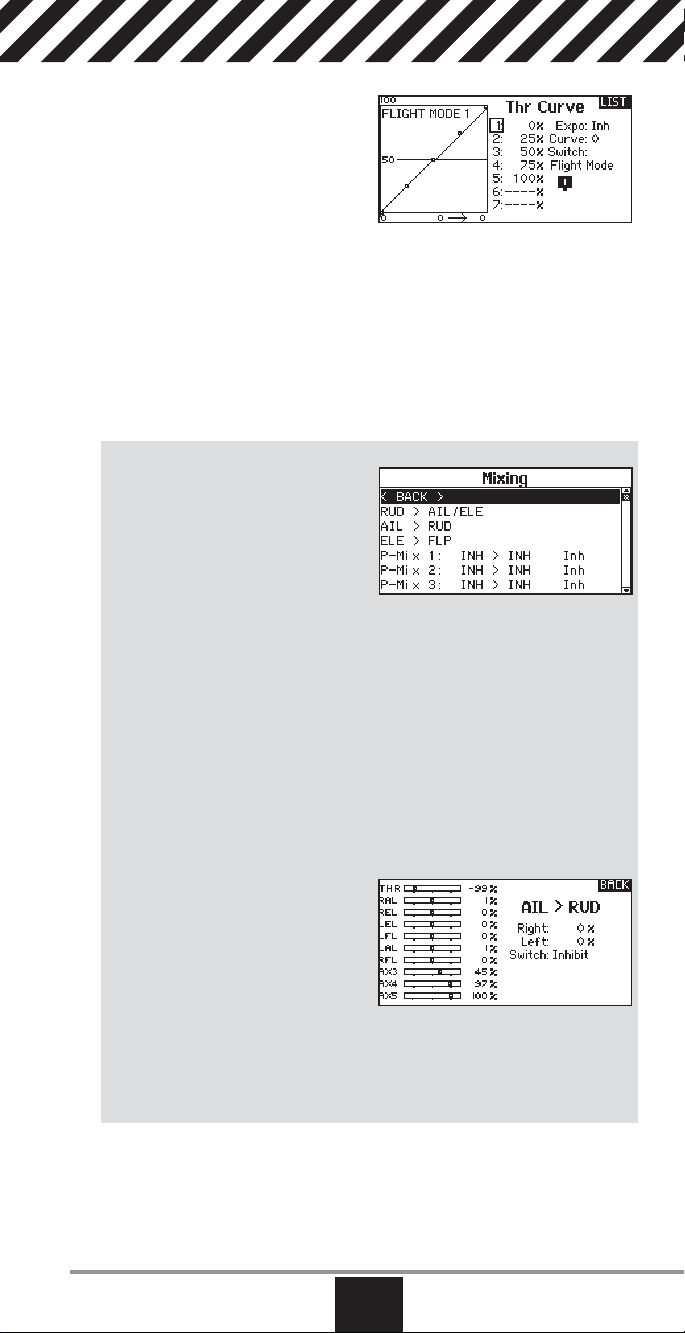
Throttle Curve
You can use the Throttle Curve menu
option to optimize the throttle response.
A maximum of 7 points are available on
the throttle curve.
To add points to a Throttle Curve:
1. Move the throttle stick to the position where you wish to add the new
point.
2. Scroll to Add Pt. and press the scroll wheel to add the point.
To remove points from a Throttle Curve:
1. Move the Throttle stick until the cursor is near the point you wish to remove.
2. Scroll to Remove Pt. and press the scroll wheel once to remove the point.
If you program multiple throttle curves and you wish to edit one of the curves,
that curve must be active in the Throttle Curve screen before you can make any
changes.
Mixing
Mixing allows control input for a channel
to affect more than one channel at a
time. Mixing functions support:
• Mixing a channel to another
channel.
• Mixing a channel to itself.
• Assigning offset to a channel
• Linking primary to secondary trim.
These mixes are available for each model memory:
• 16 programmable mixes
• Cyclic to Throttle (HELI)
• Swashplate (HELI)
• Elevator to Flap (ACRO)
• Aileron to Rudder (ACRO)
Select a channel for master and slave. Inputs for the master channel control both
the master and slave channels. For example, Elevator to Flap makes elevator the
master channel and fl ap the slave channel.
Offset
Change the offset value to move the
effective center position of the slave
channel. Positive or negative value
determines the direction of the offset.
Offset is not available for curve mixes.
Trim
If the master channel trim should also adjust the slave channel, set Trim to Act.
A channel monitor on the left side of the screen shows how channels respond to
input. To view a switch-assigned mix on the monitor, the mix switch must be in
the active position.
• Rudder to Aileron/Elevator (ACRO).
• Aileron>Rudder (SAIL)
• Aileron>Flap (SAIL)
• Elevator>Flap (SAIL)
• Flap>Elevator (SAIL)
www.spektrumrc.com
EN
39
Page 40

Assigning a Mix to a Switch
If you wish to assign a mix to a switch
position:
1. Scroll to Switch and press the scroll
wheel.
2. Scroll left or right to the switch you
wish to use and press the scroll
wheel to save the selection.
3. Scroll to the switch position where you want the mix to be active.
The mix is Active when the box is fi lled and Inactive when the box is open. You
can assign a mix to be active in multiple switch positions (0,1 or 2).
CAUTION: Always do a Control Test of your model after changing mixes.
Combo Mixing
Combination Mixing is available to
create OR mixing. OR mixing allows you
to assign 2 conditions where the mix
will activate if either condition occurs.
You can also create AND mixing where
2 conditions must occur to activate the
mix.
To program Combination Mixing:
1. Activate a mix.
2. Select Combo Sw. in the Switch Selection. The Combo screen appears.
3. Select the desired switch and active switch position for Switch 1.The mix is
Active when the switch position box is fi lled.
4. Select the Relation (AND, OR)
5. Select the desired switch and active switch position for Switch 2.The mix is
Active when the switch position box is fi lled.
6. Press the BACK button to save the Combination Mix.
The Master (left side) names are inputs. For example, “Aileron” refers to the
Aileron Stick. The Slave (right side) name is the name of the channel receiving the
mix command when the Master channel
moves.
Back Mixing
Back Mixing applies a mix to all related
servos in a wing or tail type. For example, if you select 2 AIL, 2 FLAP in the
Aircraft Type screen, a mix to one aileron
channel affects both aileron servos.
The mix response, however, depends on the aileron channel included in the mix.
A Back Mix also enables you to use fewer mixes to achieve the desired response,
for example adding roll to a split elevator.
1/2 Mixing Values
When adjusting the mix values near center (below 10), 1/2% mix values are
available for fi ne adjustment capability.
IMPORTANT: This function is only available in program mixes and rudder to
aileron/elevator in aircraft model type.
40
EN
SPEKTRUM DX18QQ
Page 41
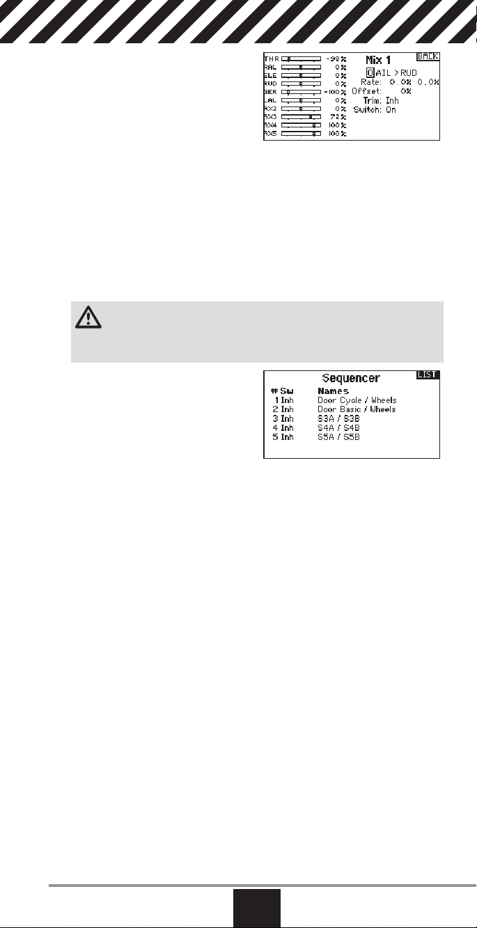
Origin Mixing
Origin Mixing uses true stick position
as the input for a mix. When origin
mixing is selected, any other settings
to the master channel will be ignored
and the mix will be based strictly on
stick position and trim position. When
Aileron, Elevator, or Rudder are selected as the master, origin mixing is available. Once Aileron, Elevator, or Rudder are selected, an N will appear next to the
master channel, where N means normal. Roll and select the N to change to O for
origin mixing. Next, select the slave channel and set the switch and mix rates as
desired.
Sequencer
The Sequencer menu option provides this-then-that mixing with a time delay. Five
different sequences (S1 through S5) are available to control 2 functions each (A
and B), in 2 timing directions (forward or reverse). Sequences appear throughout
function screens as assignable switches.
CAUTION: Always review the action of a sequence on the Monitor or
X-Plus Monitor screen BEFORE operating the model to ensure controls act
as desired. Failure to do so could cause a crash, resulting in property damage and
or injury.
You can program multiple functions
to sequentially activate in response to
an assigned switch. For example, an
assigned Gear switch can open gear
doors, lower the gear, then close the
doors. In reverse, gear doors open, the
gear retracts and the gear doors close.
You can assign each Sequencer function to a switch in most Function screens
such as Flight Mode, Dual Rate, Mixing, Throttle Curve, Pitch Curve, etc.
You can assign several functions to a sequence to decrease the number of controls you need to touch during complex fl ight transitions—for example, applying
your assigned dual rates and exponential when the landing gear deploys and the
fl ight mode changes.
If you select an S-Number-A sequence (e.g. S3A), the sequence operates as a
timed 5-position switch. An S-Number-B sequence operates as a timed 3-position
switch. The 5 positions correspond to the sequencer values shown on the time
delay graph in the second Sequencer screen. In a function screen, highlight each
point (0–4) and select the switch position desired for a function to be active.
When S1B (or another sequence-number-B) is selected as a switch in a function,
the sequence will operate as a timed 3-position switch. The 3 positions act as
‘kick points’ of the movement at fi xed percentages (equal thirds) of the sequencer
output. In a function screen, highlight each point (0–2) and select the switch position desired for a function to be active.
www.spektrumrc.com
EN
41
Page 42

Sequencer Set Up
1. In the fi rst Sequencer screen, select 1 of the 5 available sequences.
2. In the second Sequencer screen,
assign a switch to the sequence.
We recommend using a 2-position
switch.
Tip: If you need to use a 3-posi-
tion switch, you must assign one
direction to two adjacent switch
positions—e.g., 0 and 1. Assign the opposite direction to the third switch
position.
3. Assign the timing for the Forward and Reverse directions as desired. There
is no delay when you use the Nor option. You may also select a delay time
between 0 and 30 seconds.
4. Assign names for each sequencer function as desired.
5. Select either Step (S) or Proportional (P) for the Sequencer output.
Step: The sequence only changes at kick points. Otherwise, there is a delay
in the sequence until it reaches the next kick point.
Proportional: The sequence movement is proportional between kick points.
The sequence maintains rate and direction until it reaches the next kick point.
6. Adjust the Sequencer motion
percentages in the third screen.
For example, you may move points 1,
2 and 3 closer to the beginning of the
sequence so the motion occurs earlier.
This results in a delay between point 3
and point 4 at the end of the sequence.
Testing the Sequence
The Sequencer function determines the response for channels included
in the sequence.
Refer to the Monitor screen to see how respective channels interact
in the Sequencer.
Range Test
The Range Test function reduces the
power output. This allows for a range
test to confi rm the RF link is operating
correctly. Perform a range check at
the beginning of each fl ying session to
confi rm system operation.
To Access the Range Test screen
1. With the transmitter on and the main
or telemetry screen displayed, press the roller. The Function list displays.
2. Rotate the roller to highlight Range Test, then press the roller to access the
Range Test function.
3. With the Range Test screen displayed, push and hold the trainer button. The
screen displays Reduced Power. In this mode the RF output is reduced allowing for an operational range test of your system.
4. If you let go of the trainer button, the transmitter will go back to Full Power.
42
EN
SPEKTRUM DX18QQ
Page 43
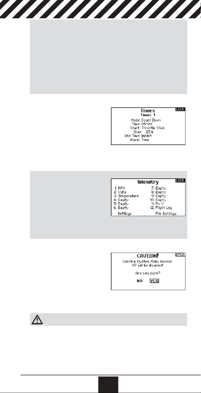
Range Testing the DX18QQ
1. With the model restrained on the ground, stand 30 paces (approx. 90 feet/28
meters) away from the model.
2. Face the model with the transmitter in your normal fl ying position and place
the transmitter into Range Test mode (see above) and push the trainer button,
reducing the power output.
3. Operate the controls. You should have total control of your model with the
transmitter in Range Test mode.
4. If control issues occur, contact the appropriate Horizon Product Support offi ce
for assistance.
5. If performing a range test while a telemetry module is active, the display will
show fl ight log data.
Timer
The DX18QQ Timer function allows you
to program a countdown timer or stop
watch (count up timer) to display on the
main screen. An alarm sounds when the
programmed time is reached. You can
program the timer to start using the assigned switch position or automatically
when throttle is raised above a programmed position. Two independent timers
can be set up as desired per model. An internal timer that shows run time for a
specifi c model displays on the Main Screen. A total system timer is also available.
Telemetry
Telemetry is in both the system setup
and the function list so you can access
the telemetry functions from either list.
You must power off the receiver and
transmitter, then power them both on to
reset the telemetry data. You can reset
min/max values by pressing
the CLEAR button.
NEVER change Telemetry settings when the aircraft is powered on. There is a brief
interruption in RF output when exiting the Telemetry screen.
System Setup
Press here to enter the System List from
the Function list without turning the
transmitter off. A Caution screen will appear that warns that RF will be disabled
(the transmitter will no longer transmit).
Press YES if you are sure and want to
access the System List. If you are not
sure, press NO to exit to the main screen and continue operation.
If you do not press YES or NO, the system will exit to the main screen and continue operation within approximately 10 seconds.
WARNING: Do not press YES unless the model is turned off or the model
is secured.
www.spektrumrc.com
EN
43
Page 44

Monitor
The Monitor screen displays the servo
positions for each channel graphically
and numerically. This is useful to verify
programming functions, trim settings,
mix directions, etc. The numeric value
is directly relative to the travel adjust
and mix values (e.g., 100% travel adjust
equals 100% value in the Monitor).
X-Plus Monitor
Use of the X-Plus Monitor requires
X-Plus to be active. The X-Plus Monitor
screen displays the output position for
each X-Plus channel graphically and
numerically. This is useful to verify
programming functions, trim settings,
mix directions, etc. The numeric value
is directly relative to the travel adjust and mix values (e.g., 100% travel adjust
equals 100% value in the X-Plus Monitor). The X-Plus Monitor shows the additional channels and requires servos which can be connected to the optional
X-Plus module and an X-Plus-capable receiver. X+1 and X+2 channels also serve
as the monitor for channels 11 and 12 on a 12 channel receiver.
CAUTION: Do NOT connect throttle or any primary control sur face
to the X-Plus Module.
44
EN
SPEKTRUM DX18QQ
Page 45

ACRO (Airplane)
Aircraft Type
NOTICE: Refer to your airplane manual for recommended
control throws.
CAUTION: Always do a Control Test of your model with the transmitter
after programming to make sure your model responds as desired.
Use the Aircraft Type Screen to select wing and tail types to match your airplane
model. Diagrams and setup names show on the transmitter screen to show the
available setups.
Refer to community.spektrumrc.com for more information about new DX18QQ
AirWare software updates to support these options.
Wing
• Normal
• Flaperon*
• Dual Aileron*
• Flaperon*
• 1 Aileron 1 Flap*
• 1 Aileron 2 Flaps*
• 2 Ailerons 1 Flap*
• 2 Ailerons 2 Flaps*
• Elevon A*
• Elevon B*
• 4 Aileron*
• 6 Aileron*
* Selection of multiple ailerons activates the Differential menu option.
** Selection of either of these activates the V-Tail Differential menu option
†
Both Canard Types are available in the Tail Type listing with Elevon A or Elevon B selected.
#
Activates the Gyro menu option in the Function List.
††
Activates Pitch in the Function List. If Pitch Curve is active, only one gyro will be available.
Tail
• Normal
• V-Tail A**
• V-Tail B**
• Dual Elevator
• Dual Rudder
• Dual Rudder/
Elevator
• Canard + 1 Rud
• Canard + 2 Rud
NEXT screen
• Gyro 1
• Gyro 2
#
#
• Pitch Curve
†
†
††
Select wing and tail types before doing any other programming.
Image Selection
Press the NEXT screen from the Aircraft
Type screen to access the Aircraft
Options screen and to select an optional
airplane image to use for the model
selected.
Recommended Servo Connections
Dual Aileron Wing
Type Connection
AB
Elevon Wing Type
Connection
E
www.spektrumrc.com
V-Tail Type
Connection
A AUX1 servo port (left aileron)
B AILE servo port (right aileron)
C ELEV servo port (left V-tail)
D RUDD servo port (right V-tail)
E AILE servo port (left aileron)
F
F ELEV servo port (right aileron)
EN
DC
45
Page 46

Elevon Servo Control
The possible servo reversing options for a delta wing model are:
Aileron Elevator
Normal Reverse
Normal Normal
Reverse Reverse
Reverse Normal
Tip: If you test all servo reversing options and the control surfaces do not move in
the correct direction, change the Elevon wing type in the System Setup list from
Elevon-A to Elevon-B.
Left
Rudder
Right
Rudder
Up
Elevator
Down
Elevator
46
Left
Aileron
Right
Aileron
EN
SPEKTRUM DX18QQ
Page 47

Flap System
The Flap System menu option enables
fl ap programming as well as elevator
mixing. You must select a fl ap-enabled
wing type in Aircraft Type or the Flap
System menu does not appear.
To activate the Flap System:
1. Access the System Setup list and
select Aircraft Type.
2. Select a fl ap-enabled wing type and exit the System Setup list.
3. Access the Function List from the Main Screen and select Flap System.
4. Select Inhibit and scroll to the switch or lever you wish to use to control the
fl ap channel.
5. Assign the Flap travel values and any desired Elevator mixing.
6. Select a Flap speed, if desired. Norm (default) does not have a delay. Flap
speed options range from 0.1s to 30 seconds.
ACRO Mixing
Rudder to Aileron/Elevator
Rudder to Aileron/Elevator mixing
corrects coupling in knife edge fl ight.
• Add Elevator mixing if the aircraft
pitches toward the landing gear or
canopy
• Add Aileron mixing if the aircraft rolls
in knife edge fl ight.
• 1/2% mixing values are available for precision adjustment
of knife edge mixing values below 10% values.
Aileron to Rudder
Use Aileron to Rudder mixing to overcome adverse yaw characteristics with
certain types of aircraft (such as high-wing aircraft).
Elevator to Flap
Elevator to Flap mixing enables Flap movement when the Elevator stick moves.
Use Elevator to Flap mixing to add the spoileron function to 3D aerobatic aircraft.
www.spektrumrc.com
EN
47
Page 48
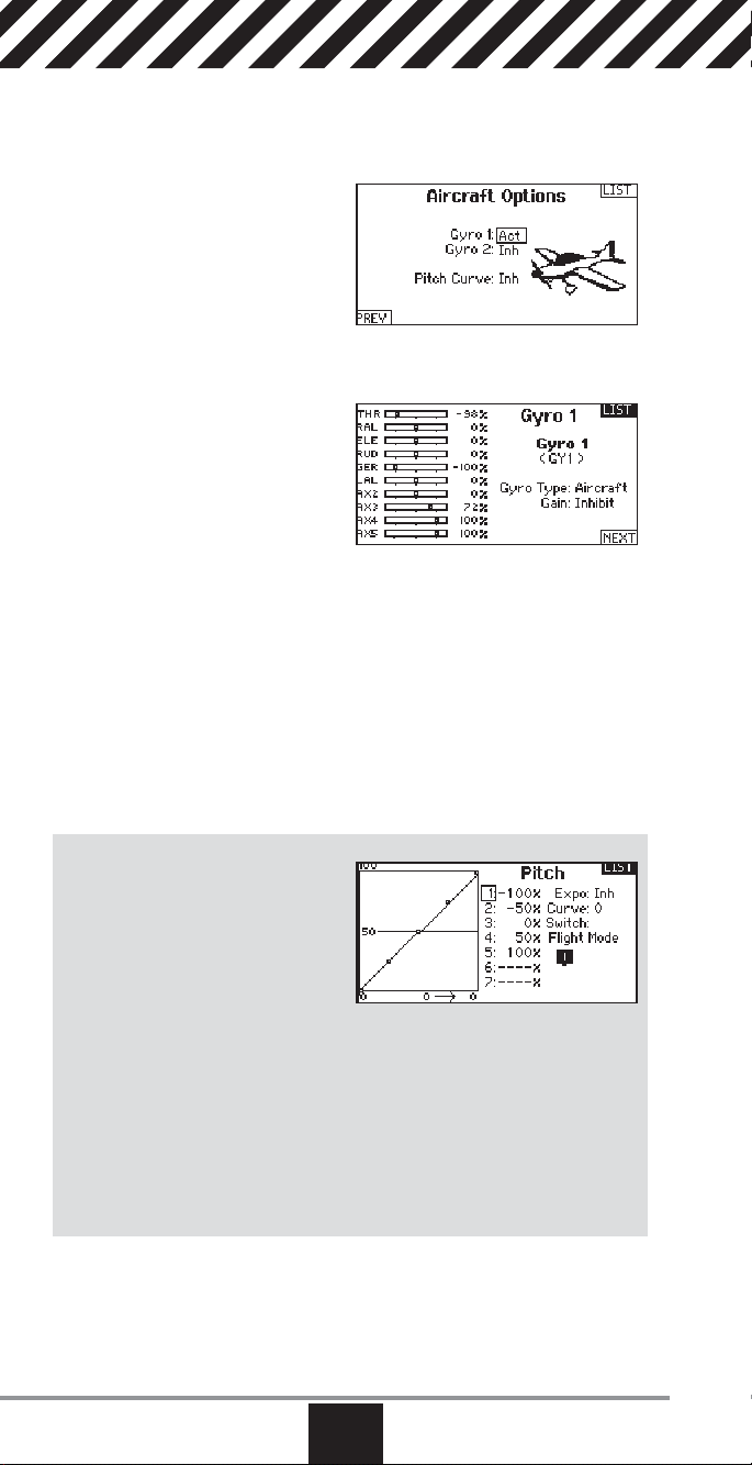
Acro Gyro Function
The Gyro menu option enables you to create up to 7 gyro gain points on a
maximum of 4 curves. Gyro gain curves also provide fl exibility in reducing gyro
gain as the control stick moves farther away from the center.
To access the Gyro screen
1. In the System Setup List, highlight
Aircraft Type
2. In the Aircraft Type Screen, select
NEXT at the bottom right of the
screen. This will access the Aircraft
Options screen. Activate the
desired Gyro function(s). When the gyro function is active, the Gyro function
appears in the Function List.
To program a Gyro curve:
1. Access the Gyro 1 or Gyro 2 menu
option from the Function list.
2. Assign either Aircraft or Heli to the
Gyro Type.
3. Select a trim or a pot to use for a
gyro gain trim if desired. Options
available include: R. Knob, L Lever, R Lever, L TrimA, and R TrimA.
4. Scroll to Inh > Inh.
a. Select the fi rst Inh and assign the input channel for the Gyro. For example,
if the gyro is installed to assist on the ailerons, select Ail.
b. Select the second Inh and assign the output channel for the Gyro, for
example, the Gear channel.
5. Select the Curve you wish to edit.
6. Add the desired gyro gain values to the points on the curve.
7. Assign the switch positions to activate the gyro curve. The curve is active
when the box is solid.
Pitch Curve Function
In Acro mode a Pitch Curve screen
is available that allows a variable
pitch propeller to be used. Up to 4
programmable curves are available that
can be selected via a switch, knob or
stick position. Up to 7 points can be
programmed at the desired position on
each curve. Note that the Pitch curve is driven by the throttle stick position.
To access the Pitch Curve screen
1. In the System Setup List, highlight Aircraft Type
2. In the Aircraft Type Screen, select NEXT at the bottom right of the screen.
This will access the Aircraft Options screen. Activate the Pitch Curve function.
When the Pitch Curve function is activated, the Pitch Curve function appears
in the Function List.
3. Assign the pitch channel in the Channel Assignment function after activating
the Pitch Curve Function.
48
EN
SPEKTRUM DX18QQ
Page 49

HELI (Helicopter)
NOTICE: Refer to your helicopter, gyro and governor manuals
for programming recommendations.
CAUTION: Always do a Control Test of your model with the transmitter
after programming changes to make sure your model responds as desired.
Swash Type
The Swash Type menu option assigns
the swash type for your particular
helicopter model.
Select the Swash Type before
completing any programming in the
Function List. The Swash Type will affect
menu options in the Function List.
Collective Type
The collective type is used to turn
on “Pull” collective for reversed
collective. Available settings are Normal
and Reverse. Press NEXT from the
Swashplate Type screen to access the
Collective Type screen. The Collective
Type allows the throttle/pitch stick to operate in reverse and ensures trims, curves
and all other functions that are to work in reverse function properly.
Image Selection
Press the NEXT screen from the
Collective Type screen to access the
Helicopter Image screen and to select
an optional helicopter image to use for
the model selected.
Pitch Curve
This function supports adjustment of
collective pitch in 5 fl ight modes.
To adjust the Pitch Curve:
1. Select the Pitch Curve you wish to
edit (N, 1 or 2).
2. Scroll right to select the points on
the curve and edit the respective values.
3. Press the BACK button to save the Pitch Curves and return
to the Function List.
www.spektrumrc.com
EN
49
Page 50

Swashplate
The Swashplate menu option enables
you to adjust the following:
• Swashplate Mix
• Exponential
• E-Ring
• Elevator Compensation
Use positive or negative Swashplate mix values as needed for correct direction
response of the helicopter.
Before making adjustments to the Swashplate mix, make sure the throttle/collective pitch input moves the entire swashplate up or down. If the servos are not
moving in the same direction, reverse them as necessary in the Servo Setup
menu option.
When the entire swashplate moves up or down:
1. Adjust the mix value for the Aileron and Elevator channels. If the servos do not
move in the correct direction, change the direction of the mix—for example,
a positive value instead of a negative value.
2. Adjust the mix value for the Pitch. If the swashplate does not move in the correct direction, change the direction of the value (negative instead of positive).
Always enable Expo when using a standard rotating-arm servo.
The Expo delivers linear movement of the swashplate from a standard rotary
servo. When Expo is inhibited, the arm on a rotary servo moves on a curved path
with decreased swashplate movement at the extremes of the servo arm travel.
NOTICE: Do not enable Expo when using a linear servo.
Electronic E-Ring
This feature prevents overdriving servos by limiting servo travel if the sum of your
cyclic and pitch inputs exceed servo limits.
Gyro
The Gyro menu option enables you
to assign a gyro gain value to an
independent switch or a Flight Mode.
Assign the receiver channel connected
to the gyro, then assign the switch for
gyro options. You can also assign values
to available switch positions
(from 1 to 5 rates are available, depending on the switch assigned). Make sure
the gyro operates correctly and compensates in the correct direction.
50
EN
SPEKTRUM DX18QQ
Page 51

Governor
The governor function is used to set
the rotor head speed when used with
a governor installed in the helicopter.
The governor onboard will control the
engine RPM to maintain the head speed
desired. You can program values for
each switch position or fl ight mode. RPM
values can be programmed in 0.5% steps.
To Program the Governor Function:
1. Access the Governor menu option.
2. Program the RPM values by rotating the scroll wheel to the desired value.
3. Press the scroll wheel and rotate it to the desired value. Press the scroll wheel
again to save the value.
IMPORTANT: The value in the display is the corrected value. 0% is 1.5ms or
OFF for most governors. Repeat this for all governor settings.
4. Assign the output channel for the Governor. The Governor and the Gyro must
be on different channels. We recommend using AUX2 for the Governor output
channel.
5. Select a switch to control the Governor.
6. Press the BACK button to save the selections and return to the Function List.
Tail Curve
The Tail Curve function mixes tail rotor
input with the throttle/collective function
to counter torque from the main rotor
blades when using a non-heading hold
(tail lock) gyro or when using rate mode
on a gyro. See Pitch Curve for more
information on programming curves.
Mixing
Cyclic to Throttle
Cyclic-to-throttle mix prevents rpm loss
when aileron, elevator or rudder inputs
are given. This mix advances the throttle
position with cyclic or rudder control
to maintain rpm. At full throttle, Cyclicto-Throttle mixing prevents the throttle
from overdriving the servo.
IMPORTANT: Do not use Cyclic to throttle mix when using a governor.
To verify that the Cyclic to Throttle mix is working properly and in the correct
direction, move the fl ight mode switch to one of the active positions. Move the
programmed cyclic or rudder channel, noting the throttle position. The throttle
position should increase.
If the throttle decreases, then the opposite value (positive vs. negative) is needed.
Swashplate
The Swashplate Mix typically corrects swashplate timing issues by mixing Aileron
to Elevator and Elevator to Aileron. When adjusted correctly, the Swashplate
causes the helicopter to roll and pitch accurately with minimal interaction.
www.spektrumrc.com
EN
51
Page 52

SAIL (Sailplane)
Sailplane Type
NOTICE: Refer to your sailplane manual for recommended
control throws.
CAUTION: Always do a Control Test of your model with the transmitter
after programming to make sure your model responds as desired.
Use the Sailplane Type Screen to select
wing and tail types to match your
sailplane model. Diagrams and setup
names show on the transmitter screen to
show the available setups.
Refer to community.spektrumrc.com for more information about
new DX18QQ AirWare updates to support these options.
Wing
• 1 Servo
• 2 Aileron*
• 2 Aileron 1 Flap*
• 2 Aileron 2 Flap*
• 4 Aileron 2 Flap*
*Selection of multiple ailerons activates the Differential menu option.
**Selection of either of these activates the V-Tail Differential menu option.
Image Selection
Press NEXT to select the sailplane image. Highlight and select the image on
screen, then use the roller to select the
image desired. Press the roller to select.
Tail
• Normal
• V-Tail A**
• V-Tail B**
Motor
• Inhibit
• Assign to a Switch (optional)
Camber Preset
Camber Preset is only available when
2 or 4 aileron wing type is selected
in Sailplane Type. The Camber Preset
function enables you to program the
ailerons, fl aps, wing tips and elevator for
a specifi c position in each Flight Mode.
If fl ight modes are not active, only one
preset position is available and it is always active.
The Camber Preset Speed enables the control surfaces to transition over a period
of time, up to 30 seconds, when you change fl ight modes.
Move the fl ight mode switch to the desired position to change the
Camber Preset values.
52
EN
SPEKTRUM DX18QQ
Page 53
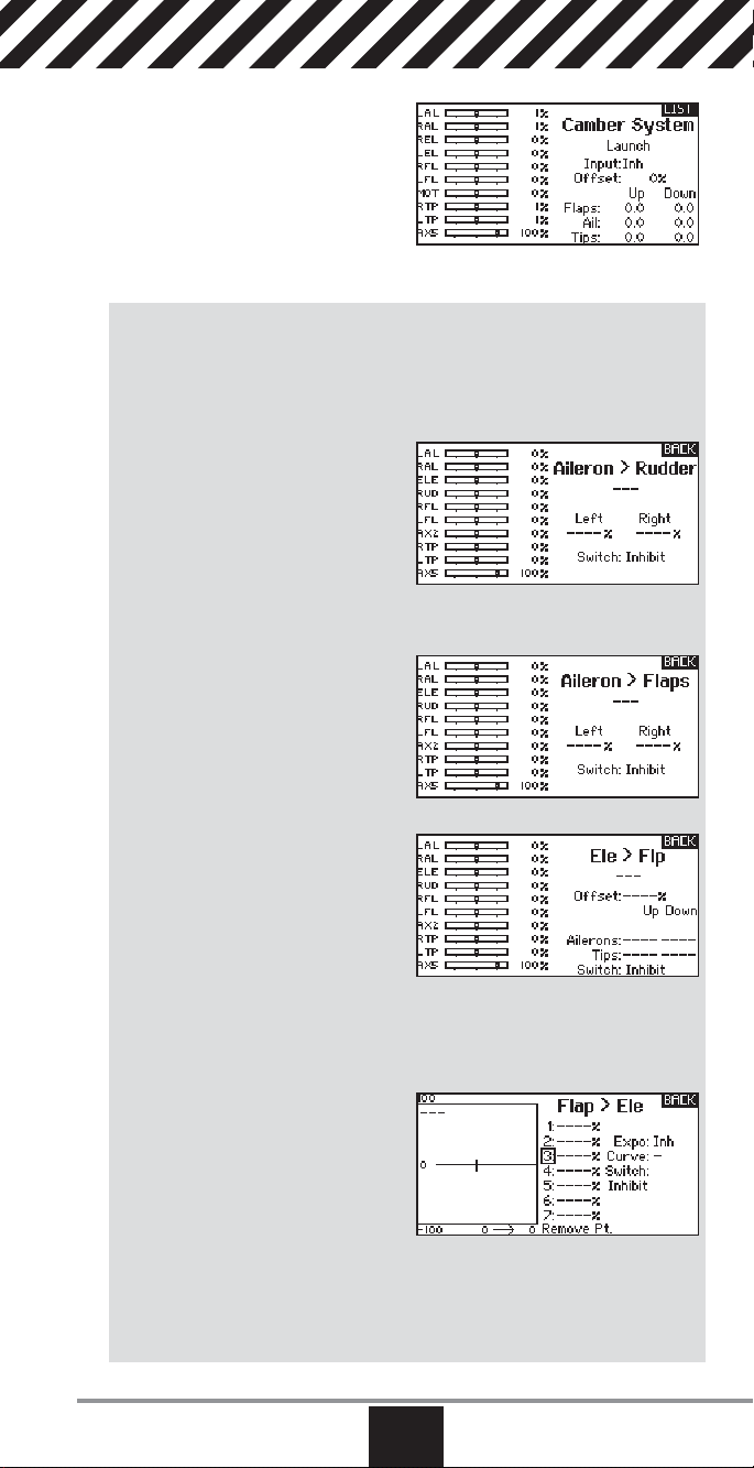
Camber System
Camber System is only available when
2 or 4 aileron wing type is selected in
Sailplane Type. The Camber System
allows in-fl ight camber adjustment and
is also used as the braking system,
often referred to as Crow or Butterfl y.
The Camber System enables you to
assign the Camber System to a different switch in each fl ight mode.
SAIL Mixing
For each of these mixes, you can program each fl ight mode with different mix
values or at 0% if no mix is desired for that specifi c fl ight mode. Programming
values include independent control of the direction and amount a slave surface
moves in relationship to the master surface.
Aileron to Rudder
The Aileron to Rudder mix is a
commonly used for coordinated turns.
When active, as aileron is applied the
rudder moves in the same direction as
the turn (right aileron input results in
right rudder output). If you assign the
fl ight mode to a switch, a Sub Switch option allows you to assign an additional
switch to activate up to 3 Aileron to Rudder mixes for that fl ight mode.
Aileron to Flap
The Aileron to Flap mix allows the entire
trailing edge of the wing (aileron and
fl ap) to operate as ailerons. When the
mix is active, the fl aps move with the
ailerons.
Elevator to Flap
Elevator to Flap mix creates additional
lift, allowing a tighter turn. The entire
trailing edge of the wing (aileron and
fl ap) operate as fl aps (camber increase)
when you apply elevator. An offset is
provided, which is typically used for
Snap Flaps. With Snap Flap, no Elevator to Flap mix occurs until the offset value is
reached. Typically, this offset is at 70% up elevator so that beyond 70% the down
fl ap mix comes in, providing additional lift for more aggressive turning (for tight
thermals or racing turns).
Flap to Elevator
Flap to Elevator mix prevents pitch up
tendency that occurs when you apply
Crow or Butterfl y. This mix is typically
used only with the Camber System. The
Flap to Elevator mix operates as a curve
so that the elevator moves down the
most during the fi rst 20% of fl ap deployment, decreases over the next 40%, then
remains the same from 60 to 100% of fl ap travel.
For sailplanes with ailerons/tips/fl aps, make sure an appropriate Sailplane Type
is selected so that tips appear in the transmitter as RAIL and LAIL. Decrease or
increase travel on the tip ailerons by creating an AIL > RAIL mix.
www.spektrumrc.com
EN
53
Page 54

Receiver Installation
And Power System Requirements
The Spektrum AR12120 PowerSafe™ receiver offers the ultimate solution for
powering high-current draw radio systems. In aircraft with multiple high-current
draw servos (e.g. giant-scale aircraft, jets, etc.), the AR12120 receiver can
provide peak current of up to 50 amps and offers true dual battery redundancy
and a fail-on soft switch for the ultimate in reliability. By locating up to four
remote receivers throughout the aircraft, the RF link can be optimized in even the
most demanding aircraft installations that have signifi cant conductive materials
like carbon, stainless steel bypass tubes, tuned exhausts, etc. For models high
in carbon fi ber content, the SPM9646 DSMX Carbon Fiber Remote Receiver is
compatible with the AR12120.
Applications
• Giant-scale aircraft
• Jets with multiple high-current draw servos
• Scale aircraft with multiple high-current draw servos and accessories (e.g. lights,
ESCs, air valves, etc.)
• Scale helicopters
Features
• True dual battery redundancy—each battery is isolated so if one fails/shorts the
other takes over.
• Utilizes up to four remote receivers for the ultimate RF link in even the most
demanding applications.
• Up to 35 amps continuous and 50 amps peak current handling capability
• Fail-on soft switch in case the switch is damaged
• Two types of failsafe—SmartSafe (throttle only) and preset failsafe (all servos)
• QuickConnect™ technology—if a power interruption (brownout) occurs, the
system
reconnects in less than 1/2 second
• Flight Log compatible
• Heavy 16AWG dual battery leads with pre-wired E-fl ite
• Compatible with all Spektrum
™
and JR® full range radio and module systems
• 2048 resolution
™
• X-Plus
compatible
IMPORTANT: The AR12120 main unit is not a typical receiver. The main unit is a
power distribution center that provides up to 35 amps of continuous and 50 amps
of peak current to power your system. Through extensive testing, our engineers
have discovered that mounting the receiver at the end of the servo and battery
leads in sophisticated aircraft (an aircraft with many high-current draw servos
and/or conductive materials) is not the optimum location to provide the clearest
RF signal. Because of this, the AR12120 PowerSafe receiver utilizes up to four
(minimum 3) remotely mounted receivers that can be placed in optimal areas of
your aircraft to provide the best possible RF link in the most demanding conditions.
®
EC3™ connectors
54
EN
SPEKTRUM DX18QQ
Page 55

Specifi cations
PowerSafe Main Unit
Voltage input: 6.0 to 10.0 volts
Minimum operational voltage: 3.5 volts
Continuous current: 35 amps
Peak current: 50 amps
Resolution: 2048
Main unit dimensions LxWxH: 46.5 x 52 x 15.3mm
Weight: 72 g
Connector type: EC3
Regulator: None
Remote Receiver
Dimensions LxWxH: 25.8 x 20.2 x 6.8mm
Weight: 3 g
Battery Requirements
Using One Battery
The PowerSafe receiver allows the option of using one or two battery packs.
When using one battery, simply plug the battery into either one of the two battery
connectors (BATT 1 or BATT2). Be sure to secure the unused battery connector.
Note that the open contacts of the unused battery are not back powered (not
electrically hot), however, the unused connector should be secured to prevent it
from entangling during fl ight. When the system is powered using one battery, a
single blue LED will constantly emit when the system is powered on.
Using Two Batteries
The PowerSafe receiver offers a true redundant dual battery system. When using two battery packs, each pack functions independently and is isolated from
the other so that if one pack should fail (open circuit, short-circuit, or become
discharged), the other battery will provide power to operate the system. When
using dual batteries, it’s important that both batteries be of the same capacity and
ideally of the same age and condition.
It’s normal for one battery to discharge slightly more than the other. This is the
nature of a redundant isolated battery system. The battery that has the higher
voltage or lower internal resistance will discharge at a faster rate. Generally the
difference is negligible (less than 10%). Because of this, it’s normal for only one
blue LED (Batt 1 or Batt 2) to be on when the system is not under a heavy current
load.
When using two batteries, the total available capacity equals the sum total of
both batteries e.g., BATT1—2000mAh + BATT2- 2000mAh = a total capacity of
4000mAh. 12- and 24-inch EC3 battery extensions are available for installations
where the battery is located a distance from the main unit.
Using Dual Voltage Regulators
Spektrum offers a 7.5 amp (11-amp peak) 6.0 volt regulator (SPMVR6007)
specifi cally designed for use with the AR12120 PowerSafe receiver.
IMPORTANT: When using two batteries powered through two regulators, each
regulator operates independently. It’s common for one battery to be discharged
at a slightly higher rate depending on the condition of the battery (internal
resistance, voltage, etc.) and the tolerance of the regulators. This makes it very
important to check each battery using a loaded battery tester (HAN171) at a
recommended 1-amp load before each fl ight, monitoring the voltage of each
pack and recharging when the weakest pack reaches 40% capacity (see Battery
Capacity below).
Battery Capacity
Select a battery (or batteries) that has more than adequate capacity to provide the
necessary fl ight time. Current draws may vary depending on your servos, installation and fl ying style.
www.spektrumrc.com
EN
55
Page 56

Recommended Guidelines for Battery Capacity
40–45% Aerobatic aircraft w/ 9–12 high-current servos: 4000–8000mAh
33–35% Aerobatic aircraft w/ 7–10 high-current servos: 3000–6000mAh
25% Quarter Scale Aerobatic aircraft w/ 5–7 high-current servos: 2000–
4000mAh
Jets — BVM Super BANDIT, F86, Euro Sport, etc.: 3000–6000mAh
Giant-Scale Jets — BVM Ultra Bandit:4000–8000mAh
Scale aircraft — The varieties of scale aircraft and the accessories they use vary
tremendously, making it diffi cult to give capacity recommendations for these
types of aircraft. Using the previously mentioned aerobatic guidelines relative
to the size and number of servos used will provide a conservative capacity for
your scale aircraft. As always, check battery charge conditions before each
fl ight.
Battery Voltage
NOTICE: D0 NOT use a 4-cell 4.8-volt battery to power the PowerSafe receiver.
4-cell 4.8-volt batteries do not provide enough voltage headroom (additional margin needed) necessary to power the system when heavily loaded. Under load, the
system voltage can drop below the voltage system’s minimum operating voltage
threshold (3.5 volts) and cause loss of control.
The PowerSafe receiver is capable of handling voltages from 6.0 to 10.0 volts.
The voltage limitations are generally the servos. Most servos are compatible with
5-cell 6-volt packs. 5-cell 6-volt NiMH packs have become the standard for many
giant-scale applications.
CAUTION: When charging Ni-MH batteries, make sure the battery fully
charges. Ni-MH batteries charged with peak detection fast chargers have
a tendency to false peak (i.e. not fully charge), which could lead to a crash.
Pilots are also using 2-cell LiPo batteries to power their aircraft. LiPo batteries
offer greater capacity for their size and weight, and are easier to manage when
charging. Before using LiPo batteries, please check the voltage specifi cations of
your servos. Use of a voltage regulator, such as the Spektrum VR6007 (SPMVR6007), might be necessary.
When a battery is connected to the PowerSafe receiver, a low current drain of
less than 1mA occurs even when the switch is turned off. If the system is going
to be stored for any length of time, it’s important that the battery (or batteries) be
disconnected from the receiver to prevent over discharge.
Installation
The PowerSafe receiver requires a minimum of three remote receivers to operate,
and one receiver must be plugged into the A receiver port. Each receiver functions
independently to offer a more secure RF link in diffi cult environments. The added
security of redundancy should a failure occur will outweigh the slight additional
penalties of cost and weight.
To install the PowerSafe Main Unit:
1. Using foam or thick double-sided foam tape and tie wraps, secure the
main PowerSafe unit in the position where you would normally mount the
receiver.
2. Mount the switch on the side of your aircraft and insert the switch plug in the
port in the main unit marked SWITCH.
The PowerSafe uses a specifi cally designed switch. Conventionally wired switches
are not compatible with the PowerSafe receiver.
56
EN
SPEKTRUM DX18QQ
Page 57

Installing the Batteries
Using the given guidelines, select the battery system that best fi ts your application
and install the battery(s)/regulator(s) in your aircraft. Connect the battery to the
receiver. Spektrum batteries are pre-wired with an EC3 connector and plug
directly in. If using another brand of battery, it will be necessary to solder EC3
connectors (two are included with the AR12120) to the battery leads. If using a
regulator, install it per the guidelines included with the regulator.
Mounting the Remote Receivers
Antenna Polarization
For optimum RF link performance, it’s important that the remote antennas be
mounted in an orientation that allows for the best possible signal reception when
the aircraft is at all attitudes and positions. This is known as antenna polarization and allows the greatest exposed visual cross-section of the antennas from
all aircraft orientations. If three antennas are used, it is recommended that one
antenna be mounted vertically, one horizontally in-line with the fuselage and one
horizontally perpendicular to the fuselage (see illustrations below).This covers
the X,Y and Z axes for superb cross-section visibility in all aircraft orientations.
An optional fourth antenna can be added at an intermediate angle to offer even
greater RF link security and system redundancy.
Remote Receiver Placement Examples
• 35% aerobatic plane with single NiMH battery and three remote receivers
R2
B1
R1
AR12100
R3
• 35% aerobatic plane with dual NiMH batteries and three remote receivers
R2
R1
B1
AR12100
B2
R3
• 40% aerobatic plane with dual LiPo batteries, dual regulators and four remote
receivers
R2
B1
B2
REG-1
REG-2
R1
AR12100
R3
R4
• Jet with dual LiPo batteries, dual regulators and four remote receivers
R2
REG-1
R1
B1
REG-2
B2
AR12100
R4
R3
www.spektrumrc.com
EN
57
Page 58

Locating the Remote Receivers
While Spektrum 2.4GHz systems are far more resistant to interference caused
from internal RF generating sources, the remote receivers should be mounted as
far away as practical (typically 4” or greater if possible) from the following:
• Ignition systems
• Ignition batteries
• Ignition switches
• Engines
• ECU pumps
• Electric motors
• Receiver batteries
The remote antennas should be mounted a minimum of at least 2” apart from
each other as greater antenna separation gives improved path diversity (RF link
performance) in critical environments. In large aircraft where space is not an
issue, it is highly recommended that the antennas be mounted throughout the
aircraft as illustrated. Spektrum offers remote receiver extensions ranging from
6” to 36,” allowing the receivers to be mounted in the most optimum locations
throughout the aircraft.
Using double-sided foam tape and tie wraps, mount a minimum of three remote
receivers in your aircraft as per the illustrations and plug them into the receiver
ports.
• Fuel tanks
• Metal bypass tubes
• High-temperature components
like exhaust systems
• High-vibration areas
• Any signifi cant metallic
conductive components
Plugging in the Servos
Plug the servo leads into the appropriate ports in the PowerSafe receiver. You are
now ready to bind the system.
NOTICE: When using Y-harnesses or servo extensions, it’s important to use standard non-amplifi ed Y-harnesses and servo extensions as amplifi ed Y-harnesses
and servo extensions may cause the servos to operate erratically or not function
at all. Amplifi ed Y-harnesses were developed several years ago to boost the signal
for some older PCM systems and should not be used with Spektrum equipment.
When converting other models to Spektrum technology, ensure that all amplifi ed
Y-harnesses and/or servo extensions are replaced with conventional, non-amplifi ed versions.
The JR PCM Y-Harness with Amplifi er (JRPA133) is not compatible with the
AR12120 and should not be used.
Binding
NOTICE: In order for the system to operate, one remote receiver must be plugged
into receiver port A and two more receivers must be plugged into any other ports.
When binding the PowerSafe with three remote receivers, if a fourth remote receiver is added, the system must be re-bound to recognize the additional receiver.
It’s necessary to bind the AR12120 to the transmitter so that the AR12120 will
only recognize that specifi c transmitter, ignoring signals from any other sources. If
the PowerSafe receiver is not bound to the transmitter, the system will not operate. During binding, the servo’s failsafe positions are stored.
To Bind the PowerSafe
1. With the system hooked up and all remote receivers attached as described
previously, insert the bind plug in the BIND/DATA port in the PowerSafe
receiver.
2. Turn on the soft switch. Note that the LEDs on all receivers should be fl ashing,
indicating that the receivers are ready to bind.
3. Establish the desired failsafe stick positions, normally low throttle and fl ight
controls neutral.
4. Follow the procedures of your transmitter to enter it into bind mode. The
system will connect within a few seconds. The LEDs on all receivers should
turn solid, indicating the system has connected.
5. Remove the bind plug and store it in a convenient place.
6. After you’ve programmed your model, it’s important to rebind the system so
the true low throttle and neutral control surface positions are programmed.
58
EN
SPEKTRUM DX18QQ
Page 59

Failsafe Functions
The AR12120 PowerSafe features two types of failsafe: SmartSafe™ and Preset
Failsafe.
SmartSafe Failsafe
This type of failsafe is recommended for most types of giant-scale aircraft. Here’s
how SmartSafe works:
Receiver Power Only
When the receiver only is turned on (no transmitter signal is present), all servos
except for the throttle are driven to their preset failsafe positions, normally all
control surfaces at neutral and the landing gear down. These failsafe positions
are stored in the receiver during binding. At this time the throttle channel has no
output to avoid operating or arming an electronic speed control (if used). In glowpowered models, the throttle servo receives no input, so it remains in its current
position. Some analog servos will coast (move when powered up) slightly even
though there is no signal present. This is normal.
The receivers remain in standby mode with the blue battery LEDs lit. When the
transmitter is turned on, the receiver locates the signal (GUID), connects and
normal control resumes. When connected, the amber LEDs on all attached remote
receivers will be on.
After Connection
When the transmitter and receiver are turned on after the receiver connects to
the transmitter, normal control of all channels occurs. If loss of signal occurs,
SmartSafe drives the throttle servo to its preset failsafe position (low throttle) that
was set during binding. All other channels hold their last position. When the signal
is regained, the system immediately regains control.
SmartSafe:
• Prevents unintentional electric motor response on start-up.
• Establishes low-throttle failsafe and maintains last-commanded control surface
position if the RF signal is lost. Failsafe positions are stored via the stick and
switch positions on the transmitter during binding.
Preset Failsafe
Preset Failsafe is ideal for sailplanes and is preferred by some modelers for their
glow- and gas-powered aircraft. Here’s how Preset Failsafe works.
Receiver Power Only
When the receiver only is turned on (no transmitter signal is present), all servos
except for the throttle are driven to their preset failsafe positions, normally all
control surfaces at neutral and the landing gear down. These failsafe positions
are stored in the receiver during binding. At this time the throttle channel has
no output to avoid operating or arming an electronic speed control (if used). In
glow-powered models, the throttle servo has no input, so it remains in its current
position. The receiver remains in standby mode with the blue battery LEDs lit.
When the transmitter is turned on, the receiver locates the signal (GUID), connects
and normal control resumes. When connected, the amber LEDs on all attached
remote receivers will be on.
After Connection
When the transmitter and receiver are turned on and the receiver connects
to the transmitter, normal control of all channels occur. If loss of signal occurs,
Preset Failsafe drives all servos to their preset failsafe positions. For sailplanes
it’s recommended that the spoilers/fl aps deploy to dethermalize the aircraft,
preventing a fl yaway. Some modelers prefer to use this failsafe system to program
a slight turn and low throttle to prevent their aircraft from fl ying away. When the
signal is regained, the system immediately (less than 4 ms) regains control.
www.spektrumrc.com
EN
59
Page 60

Preset Failsafe:
• Prevents unintentional electric motor response on start-up.
• Drives all servos, except for the throttle to their preset failsafe positions, if the
receiver only is powered and no signal is present.
• Establishes preset failsafe servo positions for all channels if the signal is lost.
Programming SmartSafe
During the binding process, the bind plug is left in throughout the process and is
removed only after the receiver connects to the transmitter. After the connection
is made (confi rmed by operating the servos), the bind plug can be removed. The
receiver is now programmed for SmartSafe.
Programming Preset Failsafe
During the binding process, the bind plug is inserted in the bind port, then the
receiver is powered up. The LEDs in each receiver should blink, indicating that
the receiver is in bind mode. Before binding the receiver to the transmitter with
the receiver in bind mode, remove the bind plug. The LEDs will continue to blink.
With the control sticks and switches in the desired failsafe positions, bind the
transmitter to the receiver by putting the transmitter into bind mode. The system
should connect in less than 15 seconds. The receiver is now programmed for
preset failsafe.
Failsafe positions are stored via the stick and switch positions on the transmitter
during binding.
QuickConnect™ with Brownout Detection
The remote receivers now included with the AR12120 feature QuickConnect with
Brownout Detection (Brownout Detection is not available with DSMX technology).
Should a power interruption occur (brownout), the system will reconnect immediately when power is restored and the LEDs on each connected receiver will fl ash,
indicating a brownout (power interruption) has occurred (DSM2 only). Brownouts
can be caused by an inadequate power supply (weak battery or regulator), a loose
connector, a bad switch, an inadequate BEC when using an electronic speed
controller, etc. Brownouts occur when the receiver voltage drops below 3.2 volts
thus interrupting control as the servos and receiver require a minimum of 3.2
volts to operate.
How Brownout Detection Works
When the receiver voltage drops below 3.2 volts the system drops out (ceases to
operate). When power is restored, the receivers will immediately attempt to reconnect to the last two frequencies they were connected to. If the two frequencies
are present (the transmitter was left on) the system reconnects, typically in about
4ms. The receivers will then blink, indicating a brownout has occurred (DSM2
only). If at any time the receiver is turned off then back on and the transmitter is
not turned off, the receivers will blink, as a power interruption was induced by
turning off the power to the receiver (DSM2 only). In fact this simple test (turning
the receiver off then on) will allow you to determine if your system’s brownout
detection is functioning (DSM2 only).
If a brownout occurs in-fl ight, it is vital that the cause of the brownout be determined and corrected. QuickConnect and Brownout Detection are designed to
allow you to safely fl y through most short duration power interruptions. However,
the root cause of these interruptions must be corrected before the next fl ight to
prevent catastrophic safety issues.
Storing Your System
If the system will be stored for more than two weeks, it’s important that the battery be disconnected from the PowerSafe receiver or from the regulator (if used).
The receiver draws a small amount of current (less than 1mA) even when the
switch is turned off. This causes the battery to drain and could result in damage
to the battery if left attached for an extended period. This is especially important
when using LiPo batteries as irreversible damage could occur.
60
EN
SPEKTRUM DX18QQ
Page 61

Physical Transmitter Adjustments
Transmitter Mode Conversion
You can change transmitter modes among Modes 1, 2, 3 and 4. This conversion
requires both a programming and a mechanical change.
Programming Conversion:
1. Access the System Settings menu from the Setup List and select the desired
Mode.
2. Exit the System Settings menu to save the selection.
3. Power off the transmitter and remove the transmitter battery pack.
After you change the transmitter Mode in the Setup List, you will need to make
mechanical changes to the transmitter gimbals.
Mechanical Conversion
CAUTION: Always power off the transmitter, disconnect and remove the
battery before adjusting stick tension or friction straps. Not doing so could
result in property damage or injury.
Mechanical conversion is required to change between Modes 1 and 2 or between
Modes 3 and 4. The mechanical conversion consists of the following steps:
1. Change the Throttle Ratchet
2. Adjust the Elevator Centering Screw
3. Move the Throttle Limit Wedges
Changing the Throttle Ratchet
1. Carefully pull the top of the rear
grips and side rubber panels away
from the transmitter.
2. Remove the four Phillips head
screws that secure the lower
transmitter case half.
3. Put the transmitter face down on
a piece of foam or a towel and
remove the lower back case. Carefully set the back case aside.
4. Locate the silver throttle friction
straps on both gimbals. One strap
engages a serrated section on the
gimbal for a ratcheted throttle,
while the other strap engages the
smooth section on the gimbal.
5. To change the throttle ratchet,
loosen the throttle strap so it does
not touch the throttle gimbal.
Tighten the opposite throttle strap
to engage the desired throttle
ratchet.
www.spektrumrc.com
EN
61
Page 62

Adjusting the Elevator Centering Screw
When changing between Modes 1 and 2, or between Modes 3 and 4, you must
adjust the elevator centering screw.
1. Hold the Elevator or Throttle stick
in the full up or full down position
when you are adjusting the elevator
centering screw. Holding the gimbal
stick reduces the load on the elevator
centering mechanism and makes it
easier to adjust the centering screw.
2. Locate the gimbal where the elevator
centering spring is engaged. Use a
Phillips screwdriver to tighten the
elevator centering screw. Tightening
the screw will disengage the centering spring.
3. Using a Phillips screwdriver, loosen the opposite elevator centering screw until
the lever engages.
Moving the Throttle Limiting Wedges
Throttle limiting wedges are used to limit the maximum throttle travel. When
changing between Modes 1 and 2, or between Modes 3 and 4, you must move
the throttle limit wedges.
1. Use a Phillips screwdriver to remove
the throttle limiting wedges from the
current positions.
2. Install the throttle limit wedges on the
opposite gimbal.
Re-assembling the Transmitter
1. Put the back of the transmitter case on the main case, taking care to not
pinch any wires or the rubber grips.
2. Install and tighten the four Phillips screws.
3. Install the top of the rubber grips on the transmitter.
Adjust Stick Tension
Adjust stick tension using the screws on the stick gimbals through holes in the
back of the transmitter.
1. Remove rubber plugs from holes marked with a vertical arrow or a horizontal
arrow.
2. Turn the screws in these holes a small amount using a small Phillips screwdriver to adjust tension on the vertical and horizontal gimbals.
NOTICE: Always do a test of stick tension while turning these screws to ensure
stick tension is not too loose or too tight. Tightening a screw too much can damage a spring. Loosening a screw too much can let a spring fall off and cause
short-circuit in the transmitter.
CAUTION: Always power off the transmitter, disconnect and remove the
battery before adjusting stick tension or friction straps. Not doing so could
result in property damage or injury.
62
EN
SPEKTRUM DX18QQ
Page 63

Function
Throttle friction strip tension screws
1
2
Gimbal spring covers
Friction straps access screws
3
(Changing the Throttle Ratchet)
1
2
3
Adjust Throttle Friction Straps
To adjust Throttle Friction:
1. Pull up the top of the rear grip on the back of the transmitter to adjust the friction strip on the throttle gimbal. Only the top of the grip must be pulled up to
access the adjustment screw. The entire grip does not need to be removed.
2. Use a small Phillips screwdriver to tighten or loosen the screw for the friction
strip.
3. Reinstall the top of the rear grip after completing the
adjustment as desired.
CAUTION: Always power off the transmitter, disconnect and remove the
battery before adjusting stick tension or friction straps. Not doing so could
result in property damage or injury.
Adjusting the Throttle Ratchet Strap
The user can loosen the friction strap screw and tighten the ratchet screw if
desired by pulling the top of the grip through the throttle adjustment opening.
No installation required, no need to remove the case back.
You can adjust the Throttle Ratchet Strap to use either a smooth throttle or ratchet
throttle.
To adjust the Throttle Ratchet Strap
1. Pull the top of the transmitter grip away from the transmitter.
2. Using a #0 Phillips screwdriver, loosen or tighten the Throttle Ratchet Strap
screw to adjust the ratchet to your liking.
3. Re-install the top of the transmitter grip on the transmitter.
Control Stick Length Adjustment
To adjust the Control Stick Length:
1. Using a 2mm Allen wrench, turn the setscrew in the stick
counterclockwise to loosen it.
2. Make the stick shorter by turning it clockwise or longer
by turn ing it counterclockwise.
3. After adjustment of stick length, tighten the setscrew.
4. Optional 34mm stick ends are included.
www.spektrumrc.com
EN
63
Page 64

2.4Ghz Troubleshooting Guide
Problem Possible Cause Solution
Move powered transmitter
a few feet from aircraft,
disconnect and reconnect
fl ight battery to aircraft
Move the aircraft or transmitter away from the large
metal object
Install bind plug in bind
port and bind the aircraft
to the transmitter
Replace/recharge batteries
Move powered transmitter
a few feet from aircraft,
disconnect and reconnect
fl ight battery to aircraft
Move the aircraft or transmitter away from the large
metal object
Rebind transmitter to the
aircraft and remove the
bind plug before cycling
power
Select correct model
memory on transmitter
Replace/recharge batteries
Bind aircraft to transmitter
Replace or contact Horizon
Product Support
Install main and remote
receivers at least 2 inches
(51mm) apart and perpendicular to each other
Completely recharge fl ight
battery
Do a check of the wires
and connection between
battery and receiver. Repair or replace wires and/
or connectors
Aircraft will not
Bind (during binding) to transmitter
Aircraft will not
link (after binding)
to transmitter
The receiver goes
into failsafe mode
a short distance
away from the
transmitter
Receiver quits
responding during
operation
Transmitter too near aircraft
during binding process
Aircraft or transmitter is too
close to large metal object
The bind plug is not installed correctly in the bind
port
Flight battery/Transmitter
battery charge is too low
Transmitter too near aircraft
during linking process
Aircraft or transmitter is too
close to large metal object
Bind plug left installed in
bind port
Aircraft bound to different
model memory
(ModelMatch™ radios only)
Flight battery/Transmitter
battery charge is too low
Transmitter may have been
bound using different DSM
protocol
Check the receiver antenna
to be sure it is not cut or
damaged
Main and remote receivers
too near each other
Low battery voltage
Loose or damaged wires or
connectors between
battery and receiver
64
EN
SPEKTRUM DX18QQ
Page 65

Problem Possible Cause Solution
Receiver loses its
bind
Receiver slowly
blinking at landing
(DSM2 Only)
Flight log registers
undesirable
number of fades,
losses or holds or
aircraft responds
irregularly to
controls
Transmitter stand or tray
could be pressing the bind
button
Bind button pressed before
transmitter powered on
Loss of power to the receiver during flight
System powered on and
connected, then receiver
powered off without powering off transmitter
Poor signal reception
Electronic feedback
Low power
If stand is pressing bind
button, remove from stand
and rebind
Rebind by performing
binding instructions
Check battery voltage
Power off transmitter when
receiver is powered off
Reposition remote receivers for improved RF signal
path diversity
Check for and stop feedback from servos or motor
systems to the ESC or
receiver
Check aircraft power
draw and increase battery power or decrease
power demand by installed
systems. Ensure all aircraft
batteries are fully charged.
Ensure the installed BEC
for an electric aircraft is
adequate for the power
demand
Parts list
Number Description
SPMB2600LPTX 2600 mAh Tx Battery: DX18QQ
SPMA3070 Battery Door: DX18QQ
SPMA3071 Back Grips (Left/Right)
SPMA3072 Side Grips (Left/Right)
SPMA3073 Rubber Plugs: DX18QQ
SPMA3074 Replacement Antenna: DX18QQ
SPM9551 International 12V Transmitter AC Adapter
SPM6708 Spektrum Single Stand Up Transmitter Case
SPM6709 Spektrum Single Stand Up Transmitter Case Foam
SPM6712 Spektrum Dual Stand Up Transmitter Case Foam: DX18QQ
SPM6803 Male/Female Universal Bind Plug
SPM9540 Spektrum Flight Log
HAN172 Digital Servo and Receiver Current Meter: Hangar 9
SPM6805 Trainer Cord
SPMA4002 Gimbal Stick 24mm Orange: DX18QQ
SPMA4003 Gimbal Stick 34mm Orange: DX18QQ
www.spektrumrc.com
EN
65
Page 66

AMA National Model Aircraft Safety Code
Effective January 1, 2011
A. GENERAL
A model aircraft is a non-human-carrying aircraft capable of sustained fl ight
in the atmosphere. It may not exceed limitations of this code and is intended
exclusively for sport, recreation and/or competition. All model fl ights must
be conducted in accordance with this safety code and any additional rules
specifi c to the fl ying site.
1. Model aircraft will not be fl own:
(a) In a careless or reckless manner.
(b) At a location where model aircraft activities are prohibited.
2. Model aircraft pilots will:
(a) Yield the right of way to all man carrying aircraft.
(b) See and avoid all aircraft and a spotter must be used when appropri-
ate. (AMA Document #540-D-See and Avoid Guidance.)
(c) Not fl y higher than approximately 400 feet above ground level within
three (3) miles of an airport, without notifying the airport operator.
(d) Not interfere with operations and traffi c patterns at any airport, heli-
port or seaplane base except where there is a mixed use agreement.
(e) Not exceed a takeoff weight, including fuel, of 55 pounds unless in
compliance with the AMA Large Model Aircraft program. (AMA Document 520-A)
(f) Ensure the aircraft is identifi ed with the name and address or AMA
number of the owner on the inside or affi xed to the outside of the
model aircraft. (This does not apply to model aircraft fl own indoors).
(g) Not operate aircraft with metal-blade propellers or with gaseous
boosts except for helicopters operated under the provisions of AMA
Document #555.
(h) Not operate model aircraft while under the infl uence of alcohol or
while using any drug which could adversely affect the pilot’s ability to
safely control the model.
(i) Not operate model aircraft carrying pyrotechnic devices which explode
or burn, or any device which propels a projectile or drops any object
that creates a hazard to persons or property.
Exceptions:
• Free Flight fuses or devices that burn producing smoke and are
securely attached to the model aircraft during fl ight.
• Rocket motors (using solid propellant) up to a G-series size may
be used provided they remain attached to the model during
fl ight. Model rockets may be fl own in accordance with the
National Model Rocketry Safety Code but may not be launched
from model aircraft.
• Offi cially designated AMA Air Show Teams (AST) are authorized
to use devices and practices as defi ned within the Team AMA
(j) Not operate a turbine-powered aircraft, unless in compliance with the
3. Model aircraft will not be fl own in AMA sanctioned events, air shows or model
demonstrations unless:
(a) The aircraft, control system and pilot skills have successfully demonstrat-
(b) An inexperienced pilot is assisted by an experienced pilot.
4. When and where required by rule, helmets must be properly worn and
fastened. They must be OSHA, DOT, ANSI, SNELL or NOCSAE approved or
comply with comparable standards.
Program Document (AMA Document #718).
AMA turbine regulations. (AMA Document #510-A).
ed all maneuvers intended or anticipated prior to the specifi c event.
66
EN
SPEKTRUM DX18QQ
Page 67

B. RADIO CONTROL (RC)
1. All pilots shall avoid fl ying directly over unprotected people, vessels, vehicles
or structures and shall avoid endangerment of life and property of others.
2. A successful radio equipment ground-range check in accordance with manufacturer’s recommendations will be completed before the fi rst fl ight of a new
or repaired model aircraft.
3. At all fl ying sites a safety line(s) must be established in front of which all fl ying
takes place (AMA Document #706-Recommended Field Layout):
(a) Only personnel associated with fl ying the model aircraft are allowed at or
in front of the safety line.
(b) At air shows or demonstrations, a straight safety line must be estab-
lished.
(c) An area away from the safety line must be maintained for spectators.
(d) Intentional fl ying behind the safety line is prohibited.
4. RC model aircraft must use the radio-control frequencies currently allowed
by the Federal Communications Commission (FCC). Only individuals properly
licensed by the FCC are authorized to operate equipment on Amateur Band
frequencies.
5. RC model aircraft will not operate within three (3) miles of any pre-existing
fl ying site without a frequency-management agreement (AMA Documents
#922-Testing for RF Interference; #923- Frequency Management Agreement)
6. With the exception of events fl own under offi cial AMA Competition Regulations, excluding takeoff and landing, no powered model may be fl own outdoors closer than 25 feet to any individual, except for the pilot and the pilot’s
helper(s) located at the fl ight line.
7. Under no circumstances may a pilot or other person touch a model aircraft in
fl ight while it is still under power, except to divert it from striking an individual.
This does not apply to model aircraft fl own indoors.
8. RC night fl ying requires a lighting system providing the pilot with a clear view
of the model’s attitude and orientation at all times.
9. The pilot of a RC model aircraft shall:
(a) Maintain control during the entire fl ight, maintaining visual contact with-
out enhancement other than by corrective lenses prescribed for the pilot.
(b) Fly using the assistance of a camera or First-Person View (FPV) only in
accordance with the procedures outlined in AMA Document #550.
Please see your local or regional modeling association’s guidelines for
proper, safe operation of your model aircraft.
www.spektrumrc.com
EN
67
Page 68

FCC Information
This device complies with part 15 of the FCC rules. Operation is subject to the
following two conditions:
1. This device may not cause harmful interference.
2. This device must accept any interference received, including interference that
may cause undesired operation.
CAUTION: Changes or modifi cations not expressly approved by the party
responsible for compliance could void the user’s authority to operate the
equipment.
This product contains a radio transmitter with wireless technology which has been
tested and found to be compliant with the applicable regulations governing a radio
transmitter in the 2.400GHz to 2.4835GHz frequency range.
Antenna Separation Distance
When operating your Spektrum transmitter, please be sure to maintain a separation distance of at least 5 cm between your body (excluding fi ngers, hands, wrists,
ankles and feet) and the antenna to meet RF exposure safety requirements as
determined by FCC regulations.
The following illustrations show the approximate 5 cm RF exposure area and
typical hand placement when operating your Spektrum transmitter.
68
EN
SPEKTRUM DX18QQ
Page 69

FAA Information
Prior to fl ying, contact your local or regional modeling organizations for guidance
and familiarize yourself with the current local rules and FAA regulations governing
model aviation in your location.
More information about model aviation can be found at www.modelaircraft.org.
The Federal Aviation Administration can be found online at www.faa.gov.
www.spektrumrc.com
EN
69
Page 70

1-Year LIMITED WARRANTY
What this Warranty Covers
Horizon Hobby, Inc., (Horizon) warrants to the original purchaser that the product purchased
(the “Product”) will be free from defects in materials and workmanship for a period of 1
years from the date of purchase.
What is Not Covered
This warranty is not transferable and does not cover (i) cosmetic damage, (ii) damage due
to acts of God, accident, misuse, abuse, negligence, commercial use, or due to improper
use, installation, operation or maintenance, (iii) modifi cation of or to any part of the Product,
(iv) attempted service by anyone other than a Horizon Hobby authorized service center, (v)
Product not purchased from an authorized Horizon dealer, or (vi) Product not compliant with
applicable technical regulations.
OTHER THAN THE EXPRESS WARRANTY ABOVE, HORIZON MAKES NO OTHER WARRANTY
OR REPRESENTATION, AND HEREBY DISCLAIMS ANY AND ALL IMPLIED WARRANTIES,
INCLUDING, WITHOUT LIMITATION, THE IMPLIED WARRANTIES OF NON-INFRINGEMENT,
MERCHANTABILITY AND FITNESS FOR A PARTICULAR PURPOSE. THE PURCHASER
ACKNOWLEDGES THAT THEY ALONE HAVE DETERMINED THAT THE PRODUCT WILL
SUITABLY MEET THE REQUIREMENTS OF THE PURCHASER’S INTENDED USE.
Purchaser’s Remedy
Horizon’s sole obligation and purchaser’s sole and exclusive remedy shall be that Horizon
will, at its option, either (i) service, or (ii) replace, any Product determined by Horizon to be
defective. Horizon reserves the right to inspect any and all Product(s) involved in a warranty
claim. Service or replacement decisions are at the sole discretion of Horizon. Proof of
purchase is required for all warranty claims. SERVICE OR REPLACEMENT AS PROVIDED
UNDER THIS WARRANTY IS THE PURCHASER’S SOLE AND EXCLUSIVE REMEDY.
Limitation of Liability
HORIZON SHALL NOT BE LIABLE FOR SPECIAL, INDIRECT, INCIDENTAL OR CONSEQUENTIAL
DAMAGES, LOSS OF PROFITS OR PRODUCTION OR COMMERCIAL LOSS IN ANY WAY,
REGARDLESS OF WHETHER SUCH CLAIM IS BASED IN CONTRACT, WARRANTY, TORT,
NEGLIGENCE, STRICT LIABILITY OR ANY OTHER THEORY OF LIABILITY, EVEN IF HORIZON
HAS BEEN ADVISED OF THE POSSIBILITY OF SUCH DAMAGES. Further, in no event shall the
liability of Horizon exceed the individual price of the Product on which liability is asserted.
As Horizon has no control over use, setup, fi nal assembly, modifi cation or misuse, no liability
shall be assumed nor accepted for any resulting damage or injury. By the act of use, setup
or assembly, the user accepts all resulting liability. If you as the purchaser or user are not
prepared to accept the liability associated with the use of the Product, purchaser is advised
to return the Product immediately in new and unused condition to the place of purchase.
Law
These terms are governed by Illinois law (without regard to confl ict of law principals). This
warranty gives you specifi c legal rights, and you may also have other rights which vary from
state to state. Horizon reserves the right to change or modify this warranty at any time
without notice.
WARRANTY SERVICES
Questions, Assistance, and Services
Your local hobby store and/or place of purchase cannot provide warranty support or service.
Once assembly, setup or use of the Product has been started, you must contact your local
distributor or Horizon directly. This will enable Horizon to better answer your questions and
service you in the event that you may need any assistance. For questions or assistance,
please visit our website at www.horizonhobby.com, submit a Product Support Inquiry, or call
877.504.0233 toll free to speak to a Product Support representative.
70
EN
SPEKTRUM DX18QQ
Page 71

Inspection or Services
If this Product needs to be inspected or serviced and is compliant in the country you live
and use the Product in, please use the Horizon Online Service Request submission process
found on our website or call Horizon to obtain a Return Merchandise Authorization (RMA)
number. Pack the Product securely using a shipping carton. Please note that original boxes
may be included, but are not designed to withstand the rigors of shipping without additional
protection. Ship via a carrier that provides tracking and insurance for lost or damaged
parcels, as Horizon is not responsible for merchandise until it arrives and is accepted at our
facility. An Online Service Request is available at http://www.horizonhobby.com/content/_
service-center_render-service-center. If you do not have internet access, please contact
Horizon Product Support to obtain a RMA number along with instructions for submitting
your product for service. When calling Horizon, you will be asked to provide your complete
name, street address, email address and phone number where you can be reached during
business hours. When sending product into Horizon, please include your RMA number, a list
of the included items, and a brief summary of the problem. A copy of your original sales
receipt must be included for warranty consideration. Be sure your name, address, and RMA
number are clearly written on the outside of the shipping carton.
Notice: Do not ship LiPo batteries to Horizon. If you have any issue with a LiPo
battery, please contact the appropriate Horizon Product Support offi ce.
Warranty Requirements
For Warranty consideration, you must include your original sales receipt verifying
the proof-of-purchase date. Provided warranty conditions have been met, your Product
will be serviced or replaced free of charge. Service or replacement decisions are at the sole
discretion of Horizon.
Non-Warranty Service
Should your service not be covered by warranty service will be completed and
payment will be required without notifi cation or estimate of the expense unless
the expense exceeds 50% of the retail purchase cost. By submitting the item for
service you are agreeing to payment of the service without notifi cation. Service estimates
are available upon request. You must include this request with your item submitted for
service. Non-warranty service estimates will be billed a minimum of ½ hour of labor. In
addition you will be billed for return freight. Horizon accepts money orders and cashier’s
checks, as well as Visa, MasterCard, American Express, and Discover cards. By submitting
any item to Horizon for service, you are agreeing to Horizon’s Terms and Conditions found on
our website http://www.horizonhobby.com/content/_service-center_render-service-center.
NOTICE: Horizon service is limited to Product compliant in the country of use and
ownership. If non-compliant product is received by Horizon for service, it will be
returned unserviced at the sole expense of the purchaser.
www.spektrumrc.com
EN
71
Page 72

Warranty and Service Contact Information
Country of
Purchase
United States
of America
United
Kingdom
Germany
France
China
Horizon Hobby Address
Horizon
Service Center
(Electronics
and engines)
Horizon
Product Support
(All other
products)
Horizon Hobby
Limited
Horizon
Technischer
Service
Horizon Hobby
SAS
Horizon Hobby
– China
4105 Fieldstone Rd
Champaign, Illinois,
61822 USA
Units 1-4 Ployters Rd
Staple Tye
Harlow, Essex
CM18 7NS,
United Kingdom
Christian-JungeStraße 1
25337 Elmshorn,
Germany
11 Rue Georges
Charpak
77127 Lieusaint,
France
Room 506, No. 97
Changshou Rd.
Shanghai, China
200060
Parts Contact Information
Country of
Purchase
United States Sales
United
Kingdom
Germany
France
China
Horizon Hobby Address
4105 Fieldstone Rd
Champaign, Illinois,
61822 USA
Units 1-4 Ployters Rd
Horizon Hobby
Limited
Horizon Hobby
GmbH
Horizon Hobby
SAS
Horizon Hobby
– China
Staple Tye
Harlow, Essex
CM18 7NS
United Kingdom
Christian-JungeStraße 1
25337 Elmshorn,
Germany
11 Rue Georges
Charpak
77127 Lieusaint,
France
Room 506, No. 97
Changshou Rd.
Shanghai, China
200060
Phone Number/Email
Address
877-504-0233
Online Repair Request: visit
www.horizonhobby.com/service
877-504-0233
productsupport@
horizonhobby.com
+44 (0) 1279 641 097
sales@horizonhobby.co.uk
+49 (0) 4121 2655 100
service@horizonhobby.de
+33 (0) 1 60 18 34 90
infofrance@horizonhobby.com
+86 (021) 5180 9868
info@horizonhobby.com.cn
Phone Number/Email
Address
800-338-4639
sales@horizonhobby.com
+44 (0) 1279 641 097
sales@horizonhobby.co.uk
+49 (0) 4121 2655 100
service@horizonhobby.de
+33 (0) 1 60 18 34 90
infofrance@horizonhobby.com
+86 (021) 5180 9868
info@horizonhobby.com.cn
72
EN
SPEKTRUM DX18QQ
Page 73

Compliance Information for the European Union
AT BE BG CZ CY DE DK
ES FI FR GR HU IE IT
LT LU LV MT NL PL PT
RO SE SI SK UK
Declaration of Conformity
(in accordance with ISO/IEC 17050-1)
No. HH20120501
Product(s): SPM DX18QQ Transmitter
Item Number(s): SPM18800EU
Equipment class: 2
The object of declaration described above is in conformity with the requirements of the
specifi cations listed below, following the provisions of the European R&TTE directive
1999/5/EC, EMC Directive 2004/108/EC and LVD Directive 2006/95/EC:
EN 300-328 V1.7.1: 2006
EN 301 489-1 V1.7.1: 2006
EN 301 489-17 V1.3.2: 2008
EN 60950-1:2006+A12:2011
EN55022: 2010
EN55024: 2010
EN61000-3-2:2006+A1:2009+A2:2009
EN61000-3-3:2008
Signed for and on behalf of:
Horizon Hobby, Inc.
Champaign, IL USA
May 1, 2011
Executive Vice President and Chief Operating Offi cer
International Operations and Risk Management
Steven A. Hall
Horizon Hobby, Inc.
Instructions for disposal of WEEE by users
in the European Union
This product must not be disposed of with other waste. Instead, it
is the user’s responsibility to dispose of their waste equipment by
handing it over to a designated collections point for the recycling of
waste electrical and electronic equipment. The separate collection
and recycling of your waste equipment at the time of disposal will
a manner that protects human health and the environment. For more information about where you can drop off your waste equipment for recycling, please
contact your local city offi ce, your household waste disposal service or where you
purchased the product.
help to conserve natural resources and ensure that it is recycled in
www.spektrumrc.com
EN
73
Page 74

Notes
72
© 2012 Horizon Hobby, Inc.
The Spektrum trademark is used with permission
DSM2, AirWare, SimpleScroll, JR, Vibe, X-Plus and
Bind-N-Fly are trademarks or registered trademarks
DSMX is a trademark of Horizon Hobby, Inc.,
SD Logo is a trademark of SD-3C, LLC
US 7,391,320. Other patents pending.
Created 8/12 37743 SPM18800
of Bachmann Industries, Inc.
of Horizon Hobby, Inc.
registered in the US.
www.spektrum-rc.com
ES
SPEKTRUM DX18QQ
 Loading...