


ATEE9AGP173TW01
Table of contents
 Loading...
Installation Instructions
for Stacked W
asher/Dryers
Original Instructions
Keep These Instructions for Futur
(If this machine changes ownership, this manual must accompany machine.)
e Reference.
www.speedqueen.com
Part No. 804671ENR3
June 2016

WARNING
WARNING
Risk of fire. Highly flammable material.
IMPORTANT: Purchaser must consult the local gas
supplier for suggested instructions to be followed if
the dryer user smells gas. The gas utility instructions
plus the SAFETY and WARNING note directly above
must be posted in a prominent location near the dryer
for customer use.
W881
Read all instructions before using unit.
WARNING
FOR YOUR SAFETY, the information in this manual
must be followed to minimize the risk of fire or explosion or to prevent property damage, personal injury or death.
W033
WARNING
• Do not store or use gasoline or other flammable
vapors and liquids in the vicinity of this or any
other appliance.
• WHAT TO DO IF YOU SMELL GAS:
• Do not try to light any appliance.
• Do not touch any electrical switch; do not use
any phone in your building.
• Clear the room, building or area of all occu-
pants.
• Immediately call your gas supplier from a
neighbor’s phone. Follow the gas supplier’s instructions.
• If you cannot reach your gas supplier, call the
fire department.
• Installation and service must be performed by a
qualified installer, service agency or the gas supplier.
WARNING
• Installation of unit must be performed by a qualified installer.
• Install clothes dryer according to manufacturer’s
instructions and local codes.
• DO NOT install a clothes dryer with flexible plastic venting materials. If flexible metal (foil type)
duct is installed, it must be of a specific type
identified by the appliance manufacturer as suitable for use with clothes dryers. Refer to section
on connecting exhaust system. Flexible venting
materials are known to collapse, be easily crushed, and trap lint. These conditions will obstruct
clothes dryer airflow and increase the risk of fire.
W729R1
WARNING
To reduce the risk of severe injury or death, follow all
installation instructions. Save these instructions.
W894
WARNING
FOR YOUR SAFETY
Do not store or use gasoline or other flammable vapors and liquids in the vicinity of this or any other
appliance.
W053
©
Copyright, Alliance Laundry Systems LLC -
DO NOT COPY or TRANSMIT
W052
This product uses FreeRTOS V7.2.0 (www.freertos.org).
3 Part No. 804671ENR3

The following information applies to the state of Massachusetts,
USA.
• This appliance can only be installed by a Massachusetts licensed plumber or gas fitter.
• This appliance must be installed with a 36 inch [910 mm]
long flexible gas connector.
• A “T-Handle” type gas shut-off valve must be installed in the
gas supply line to this appliance.
• This appliance must not be installed in a bedroom or bathroom.
©
Copyright, Alliance Laundry Systems LLC -
DO NOT COPY or TRANSMIT
4 Part No. 804671ENR3

Table of Contents
...............................................................................................................3
Dimensions............................................................................................. 6
Installation............................................................................................. 9
Before You Start............................................................................................. 9
Tools..........................................................................................................9
Parts Included............................................................................................. 9
Removing Dryer......................................................................................... 9
Reassembling Dryer.................................................................................... 9
Order of Installation Steps............................................................................9
Position Unit Near Installation Area............................................................... 10
Remove Shipping Materials........................................................................... 10
Connect Fill Hoses........................................................................................ 11
Water Supply Requirements........................................................................11
Connecting Hoses......................................................................................11
Risers.......................................................................................................12
Connect Drain Hose to Drain Receptacle.........................................................12
Standpipe Installation................................................................................ 12
Wall Installation........................................................................................ 13
Laundry Tub Installation............................................................................13
Gas Dryers - Connect Gas Supply Pipe........................................................... 13
Electric Dryer Only - Connect Electrical Plug..................................................15
Earth/Ground Information.......................................................................... 15
Connecting Power Cord with Three-Wire Plug.............................................15
Connecting Power Cord with Four-Wire Plug.............................................. 17
Connect Dryer Exhaust System...................................................................... 19
Exhaust Direction......................................................................................20
Exhaust System.........................................................................................20
Position and Level the Unit............................................................................20
Wipe Out Inside of Washer and Dryer Drums.................................................. 22
Plug In the Washer and Dryer.........................................................................22
Electric Dryer........................................................................................... 22
Gas Dryer................................................................................................. 22
Washer..................................................................................................... 24
Check Installation......................................................................................... 25
Check Heat Source........................................................................................25
Electric Dryers.......................................................................................... 25
Gas Dryers................................................................................................26
Installer Checklist.................................................................................27
©
Copyright 2016, Alliance Laundry Systems LLC
All rights reserved. No part of the contents of this book may be reproduced or transmitted in any form or by any means without the expressed
written consent of the publisher.
©
Copyright, Alliance Laundry Systems LLC -
DO NOT COPY or TRANSMIT
5 Part No. 804671ENR3
Electric Models
SWD1003N_SVG
O
Q
P
N
M
L
K
J
I
H
G
F
E
D
C
B
A
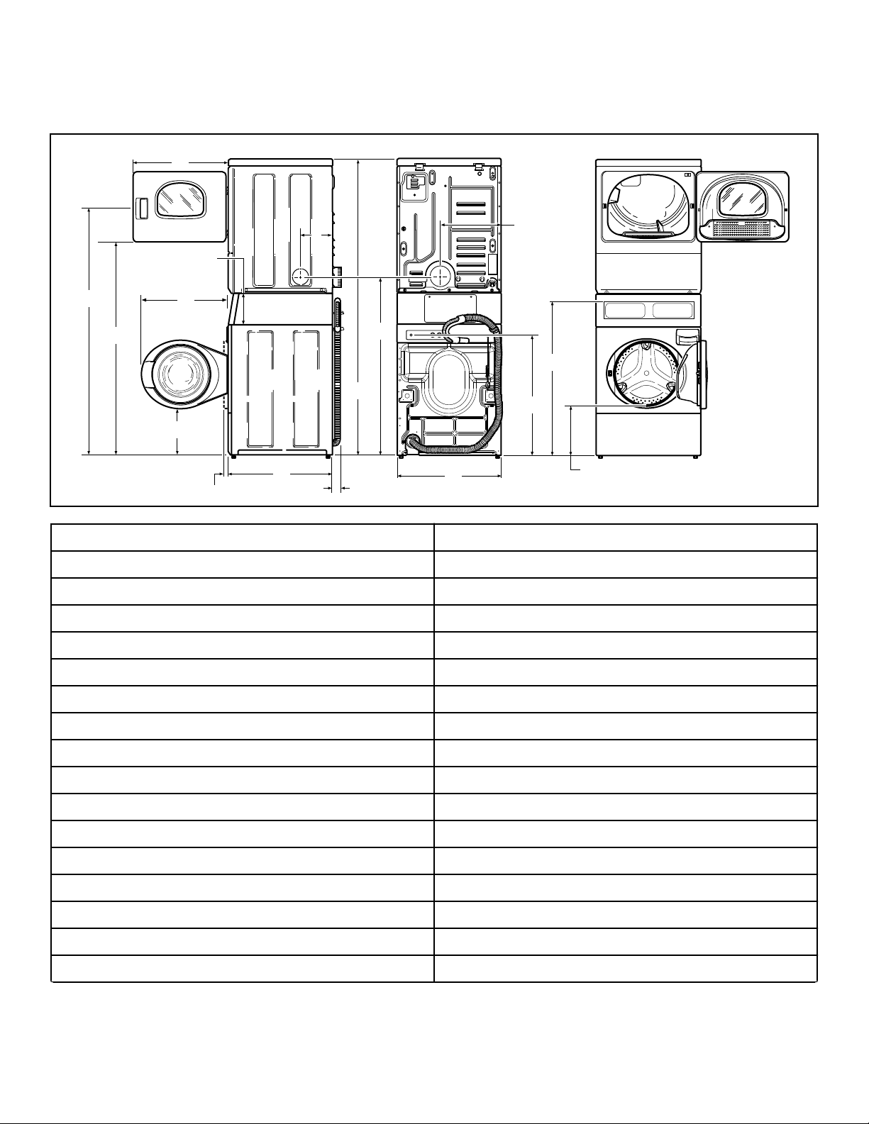
Dimensions
Dimensions
A * 66.06 in. [1678 mm]
B * 56.97 in. [1447 mm]
C 23.5 in. [597 mm]
D 8.375 in. [213 mm]
E 24 in. [610 mm]
F 8 in. [203 mm]
G 15.4 in. [391 mm]
H * 36.9 in. [938 mm]
I ** * 14.6 in. [371 mm]
J * 32 in. [813 mm]
K 26.875 in. [683 mm]
L * 46.62 in. [1184 mm]
M * 78.17 in. [1986 mm]
N 2.04 in. [52 mm]
O 27.73 in. [704 mm]
P (with door closed) 1.5 in. [38 mm]
Q * 13.1 in. [333 mm]
Table continues...
©
Copyright, Alliance Laundry Systems LLC -
DO NOT COPY or TRANSMIT
6 Part No. 804671ENR3

NOTE: Exhaust openings are 4 inch [102 mm] metal
SWD1004N_SVG
I
H
G
F
E
D
C
B
A
K
M
L
J
Q
R
O
S
P
N
1
ducting.
Gas Models
Dimensions
* With leveling legs turned into base.
** For ADA compliance turn legs out from base 0.5 inches.
1. 3/8 in. NPT Gas Connection
A *66.06 in. [1678 mm]
B *56.97 in. [1447 mm]
C 23.5 in. [597 mm]
D 8.375 in. [213 mm]
E 24 in. [610 mm]
F 8 in. [203 mm]
G 15.4 in. [391 mm]
H 2.3 in. [59 mm]
I *36.9 in. [938 mm]
J ** *14.6 in. [371 mm]
K *44.87 in. [1140 mm]
L *32 in. [813 mm]
M 26.875 in. [683 mm]
N *46.62 in. [1184 mm]
O *78.17 in. [1986 mm]
P 2.04 in. [52 mm]
©
Copyright, Alliance Laundry Systems LLC -
DO NOT COPY or TRANSMIT
7 Part No. 804671ENR3
Table continues...

Dimensions
Q 27.73 in. [704 mm]
R (with door closed) 1.5 in. [38 mm]
S *13.1 in. [333 mm]
* With leveling legs turned into base.
** For ADA compliance turn legs out from base 0.5 inches.
NOTE: Exhaust openings are 4 inch [102 mm] metal
ducting.
©
Copyright, Alliance Laundry Systems LLC -
DO NOT COPY or TRANSMIT
8 Part No. 804671ENR3
Installation
SWD1021N_SVG
11
10
9
8
4
3
2
1
6
7
5
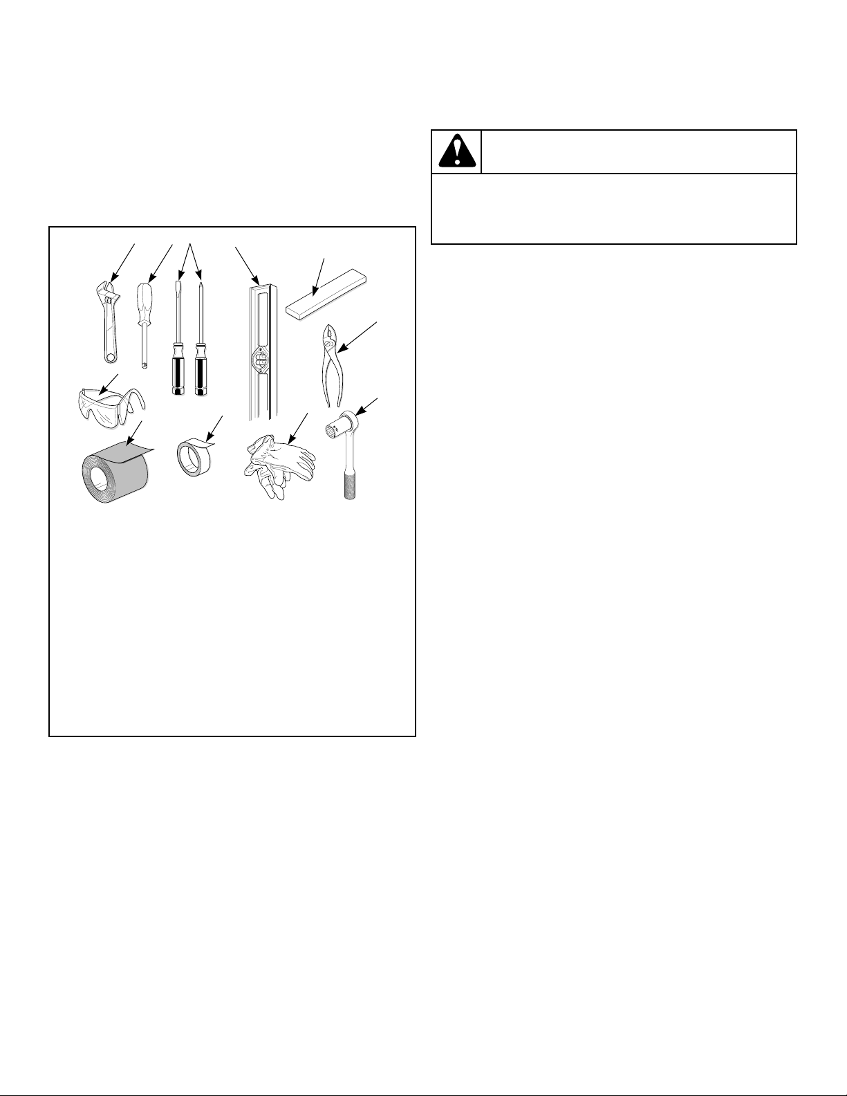
Installation
Before You Start
Tools
For most installations, the basic tools you will need are:
1. Wrench
2. 1/4 inch Driver
3. Screwdriver
4. Level
5. Wood Block
6. Pliers
7. 5/16 Inch Socket Wrench
8. Gloves
9. Teflon Tape (Gas Models)
10. Duct Tape
11. Safety Glasses
WARNING
Any disassembly requiring the use of tools must be
performed by a suitably qualified service person.
W299
Parts Included
An accessories bag has been shipped inside your unit. It includes:
• Installation Instructions
• Two User's Guides (one for washer and one for dryer)
• Warranty Bond
• Three screws (electric dryers only)
• Two fill hoses with washers and filter screens
• Four rubber feet
• Beaded strap
Removing Dryer
Use the following steps if the installation requires removal of the
dryer. Two people are required to perform this task.
1. Remove dryer front access panel.
2. Remove two screws holding control panel to control cabinet.
3. Remove two 7/16 inch screws and washers attaching dryer to
washer.
4. Tip dryer back and disconnect dryer control wire harness
from main dryer wire harness.
5. Slide dryer forward until rear leveling legs slide into notches
in the control cabinet.
6. Lift dryer and place it on a level surface.
Reassembling Dryer
Figure 1
NOTE: If the unit is delivered on a cold day (below
freezing), or is stored in an unheated room or area during the cold months, do not attempt to operate it until
the unit has had a chance to warm up.
NOTE: Some moisture in the wash drum is normal. Water is used during testing at the manufacturer.
NOTE: This appliance is suitable for use in countries
having a warm, damp climate.
©
Copyright, Alliance Laundry Systems LLC -
DO NOT COPY or TRANSMIT
1. Lift dryer and place it on top of washer so dryer leveling legs
sit in notches in control cabinet.
2. Slide dryer backward until mounting holes in base line up
with holes in front of security cabinet.
3. Reconnect dryer wire harness. If needed, refer to unit’s wiring
diagram.
4. Tip dryer and replace two 7/16 inch screws and washers holding dryer to washer.
5. Reattach the control panel to the control cabinet using two
screws.
6. Replace dryer’s front access panel.
Order of Installation Steps
9 Part No. 804671ENR3
Loading...