


40-40M
Table of contents
 Loading...
Model 40/40M
Multi IR Hydrocarbon and Hydrogen
Flame Detector
User Guide
FM, CSA Approved
Class I Div. 1 Groups B, C, D
Class II/III Div. 1 Groups E, F, G
ATEX, IECEx Approved
Ex II 2 GD, Exde IIC T5 (75°C)
Document ref: TM 40/40M, Rev (6) July 2013
218 Little Falls Rd., Cedar Grove, NJ 07009, USA
Phone: +1 (973) 239 8398 Fax: +1 (973) 239 761
Web-Site: www.spectrex.net; Email: spectrex@spectrex.net

Multi IR Hydrocarbon and Hydrogen Flame Detector User Guide
ii

Legal Notice iii
Legal Notice
The SharpEye Optical Flame Detector described in this document is the property of Spectrex,
Inc.
No part of the hardware, software or documentation may be reproduced, transmitted,
transcribed, stored in a retrieval system or translated into any language or computer language,
in any form or by any means, without prior written permission of Spectrex, Inc.
While great efforts have been made to assure the accuracy and clarity of this document,
Spectrex, Inc. assumes no liability resulting from any omissions in this document, or from
misuse of the information obtained herein. The information in this document has been carefully
checked and is believed to be entirely reliable with all of the necessary information included.
Spectrex Inc. reserves the right to make changes to any products described herein to improve
reliability, function, or design, and reserves the right to revise this document and make
changes from time to time in content hereof with no obligation to notify any persons of
revisions or changes. Spectrex, Inc. does not assume any liability arising out of the application
or any use of any product or circuit described herein; neither does it convey license under its
patent rights or the rights of others
Warning: This manual should be read carefully by all individuals
who have or will have responsibility for using, maintaining or
servicing the product.
The Detector is not field-repairable due to the meticulous
alignment and calibration of the sensors and the respective
circuits. Do not attempt to modify or repair the internal circuits
or change their settings, as this will impair the system's
performance and void the Spectrex, Inc. Product warranty.
Warranty
SPECTREX INC. Agrees to extend to Purchaser/Distributor a warranty on the SPECTREX
supplied components of the SharpEye products. SPECTREX warrants to Purchaser/Distributor
that the products are free from defects in materials and workmanship for a period of five (5)
years, commencing with the date of delivery to Purchaser/Distributor. SPECTREX expressly
excludes damage incurred in transit from the factory or other damage due to abuse, misuse,
improper installation, or lack of maintenance or “Act of God” which are above and beyond its
control. SPECTREX will, upon receipt of any defective product, transportation prepaid, repair or
replace it at its sole discretion if found to have been defective when shipped. Said repair or
replacement is SPECTREX’S sole liability under this warranty and SPECTREX’S liability shall be
limited to repair or replacement of the component found defective and shall not include any
liability for consequential or other damages. The customer is responsible for all freight charges
and taxes due on shipments both ways. This warranty is exclusive of all other warranties
express or implied.

Multi IR Hydrocarbon and Hydrogen Flame Detector User Guide
iv
Release History
Rev
Date
Revision History
Prepared by
Approved by
0
July 15,2008
First Release
Ian Buchanan
Eric Zinn
1
September 23, 2008
Second Release
Ian Buchanan
Eric Zinn
2
July, 2010
Third Release
Ian Buchanan
Eric Zinn
3
August 2010
Fourth Release
Ian Buchanan
Eric Zinn
4
November 2010
Fifth Release
Ian Buchanan
Eric Zinn
5
February 2013
Sixth Release
Ian Buchanan
Eric Zinn
6
July 2013
Seventh Release
Ian Buchanan
Eric Zinn

About this Guide v
About this Guide
This guide describes the SharpEye Model 40/40M Multi IR Flame Detector
and its features and provides instructions on how to install, operate and
maintain the detector.
This guide includes the following chapters and appendixes:
Chapter 1, Introduction, provides a general overview of the product,
principles of operation, and performance considerations.
Chapter 2, Installing the Detector, describes how to install the
detector including preparations before installation, wiring and mode
settings.
Chapter 3, Operating the Detector, describes how to power-up and
test the detector. The chapter also lists safety precautions you should
take when operating the detector.
Chapter 4, Maintenance and troubleshooting, describes basic
maintenance procedures, and troubleshooting and support procedures.
Appendix A, Technical Specifications: Lists the detectors technical
and other specifications.
Appendix B, Wiring Instructions, lists the wiring instructions for
connecting the detector and also provides examples of typical wiring
configurations.
Appendix C, RS-485 Communication Network, provides an overview
of the RS-485 communications network.
Appendix D, Accessories, describes the accessories available for the
detector.
Appendix E, SIL-2 Features, describes the special conditions to
comply with the requirements of EN 61508 for SIL 2 according to TUV.

Multi IR Hydrocarbon and Hydrogen Flame Detector User Guide
vi Abbreviations and Acronyms
Abbreviations and Acronyms
Abbreviation
Meaning
ATEX
Atmosphere Explosives
AWG
American Wire Gauge
BIT
Built In Test
EMC
Electromagnetic Compatibility
EOL
End of Line
FOV
Field of View
HART
Highway Addressable Remote Transducer-
communication protocol
IAD
Immune at Any Distance
IECEx
International Electrotechnical Commission Explosion
IPA
Isopropyl Alcohol
IR
Infrared
JP5
Jet Fuel
Latching
Refers to relays remaining in the ON state even after the
ON condition has been removed
LED
Light Emitting Diode
LPG
Liquefied Petroleum Gas
mA
MilliAmps (0.001 amps)
MODBUS
Master-slave messaging structure
N.C.
Normally Closed
N.O.
Normally Open
N/A
Not Applicable
NFPA
National Fire Protection Association
NPT
National Pipe Thread
SIL
Safety Integrity Level
UNC
Unified Coarse Thread
VAC
Volts Alternating Current

Table of Contents vii
Table of Contents
Model 40/40M Multi IR Hydrocarbon and
Hydrogen Flame Detector User Guide ............................................................... i
Legal Notice .................................................................................................... iii
Warranty ........................................................................................................ iii
Release History ............................................................................................... iv
About this Guide .............................................................................................. v
Abbreviations and Acronyms ............................................................................. vi
1 Introduction .............................................................................................. 1
1.1 Overview .............................................................................................. 1
1.2 Model and Types .................................................................................... 2
1.3 Features and Benefits ............................................................................. 4
1.4 Principles of Operation ............................................................................ 4
1.4.1 Fire Detection Principle ..................................................................... 4
1.4.2 Heated Optics .................................................................................. 5
1.4.3 HART Protocol ................................................................................. 5
1.4.4 RS-485 Modbus ............................................................................... 6
1.4.5 Product Certification ......................................................................... 6
1.5 Performance Considerations .................................................................... 7
1.5.1 Detection Sensitivity ........................................................................ 7
1.5.2 Cone of Vision ................................................................................. 9
1.5.3 False Alarms Prevention ................................................................... 11
1.5.4 Visual Indicators ............................................................................. 12
1.5.5 Output Signals ................................................................................ 13
1.5.6 Detector Status .............................................................................. 14
1.5.7 Auxiliary Relay as End-of-Line Resistor .............................................. 15
1.6 Internal Detector Tests .......................................................................... 15
1.6.1 Continuous Feature Test .................................................................. 15
1.6.2 Built-In-Test (BIT) .......................................................................... 16
2 Installing the Detector ............................................................................ 19
2.1 General Guidelines ................................................................................ 19
2.2 Unpacking the Product ........................................................................... 20
2.2.1 Checking the Product Type ............................................................... 20
2.3 Required Tools ...................................................................................... 21
2.4 Certification Instructions ........................................................................ 22

Multi IR Hydrocarbon and Hydrogen Flame Detector User Guide
viii Table of Contents
2.5 Installation Cables ................................................................................ 23
2.5.1 Conduit Installation ......................................................................... 23
2.6 Installing the Tilt Mount (part no. 40/40-001) .......................................... 24
2.6.1 Tilt Mount Assembly ........................................................................ 25
2.7 Connecting the Detector ........................................................................ 26
2.7.1 Verifying the Detector Wiring ........................................................... 28
2.8 Configuring your Detector ...................................................................... 29
2.8.1 Sensitivity ...................................................................................... 30
2.8.2 Alarm Delay ................................................................................... 30
2.8.3 Address Set-up ............................................................................... 30
2.8.4 Function Set-up .............................................................................. 31
2.8.5 Heated Optics ................................................................................. 31
3 Operating the Detector ............................................................................ 33
3.1 Powering Up ......................................................................................... 33
3.2 Safety Precautions ................................................................................ 34
3.2.1 Default Functions Settings ............................................................... 34
3.3 Testing Procedures ................................................................................ 35
3.3.1 Automatic BIT Test ......................................................................... 35
3.3.2 Manual BIT Test .............................................................................. 35
3.3.3 Testing with Fire Simulator Model 20/20-313 ..................................... 35
4 Maintenance and Troubleshooting ........................................................... 37
4.1 Maintenance ......................................................................................... 37
4.1.1 General Procedures ......................................................................... 37
4.1.2 Periodic Procedures ......................................................................... 38
4.1.3 Keeping Maintenance Records .......................................................... 38
4.2 Troubleshooting .................................................................................... 39
Appendices .................................................................................................... 41
A Specifications .......................................................................................... 43
A.1 Technical Specifications ......................................................................... 43
A.2 Electrical Specifications .......................................................................... 44
A.3 Outputs ............................................................................................... 44
A.4 Approvals............................................................................................. 46
A.5 Mechanical Specifications ....................................................................... 47
A.6 Environmental Specifications .................................................................. 47

TM 40/40M, Rev (6) July 2013
Table of Contents ix
B Wiring Instructions.................................................................................. 49
B.1 General Instructions for Electrical Wiring .................................................. 49
B.2 Typical Wiring Configurations ................................................................. 51
C RS-485 Communication Network ............................................................. 55
C.1 RS-485 Overview .................................................................................. 55
D Accessories .............................................................................................. 57
D.1 Long Range Multi IR Fire Simulator ......................................................... 57
D.1.1 Unpacking ...................................................................................... 58
D.1.2 Operating Instructions ..................................................................... 58
D.1.3 Range ........................................................................................... 59
D.1.4 Charging the Battery ....................................................................... 59
D.1.5 Technical Specifications ................................................................... 60
D.2 Tilt Mount - P/N 40/40-001 .................................................................... 60
D.3 Duct Mount P/N 777670 ......................................................................... 61
D.4 Weather Protection - P/N 777163 ............................................................ 62
D.5 Laser Detection Coverage Pointer - P/N 777166 ........................................ 63
E SIL-2 Features ......................................................................................... 65
E.1 40/40M Flame Detector ......................................................................... 65
E.1.1 Safety Relevant Parameters ............................................................. 65
E.1.2 Guidelines for Configuring, Installing, Operating and Service ................ 65
Technical Support ......................................................................................... 68

Multi IR Hydrocarbon and Hydrogen Flame Detector User Guide
x List of Figures
List of Figures
Figure 1: Vertical Field of View for Gasoline ........................................................... 9
Figure 2: Horizontal Field of View for Gasoline ...................................................... 10
Figure 3: Fields of View for Hydrogen (Horizontal and Vertical) ............................... 10
Figure 4: Indication LED ..................................................................................... 12
Figure 5: Detector with Tilt Mount ....................................................................... 24
Figure 6: Tilt Mount Assembly ............................................................................. 25
Figure 7: Tilt Mount Assembly (dimensions in mm and inches) ................................ 25
Figure 8: Detector with Cover Removed ............................................................... 27
Figure 9: Wiring Terminals ................................................................................. 51
Figure 10: Typical Wiring for 4 Wire Controllers (Using Option 1 or 2 Wiring) ............ 52
Figure 11: 0-20mA Wiring Option 1 (Sink 4-Wire) - Default .................................... 53
Figure 12: 0-20mA Wiring Option 1 (Converted to Source 3-Wire) .......................... 53
Figure 13: 0-20mA Wiring Option 1 (Non-isolated Sink 3-Wire) ............................... 54
Figure 14: 0-20mA Wiring Option 2 and 3 (Source 3-Wire
available with the HART Protocol) ........................................................................ 54
Figure 15: RS-485 Networking ............................................................................ 55
Figure 16: SharpEye Multi IR Long Range Fire Simulator 20/20-313 ........................ 57
Figure 17: 40/40M Multi IR Detector Target Point .................................................. 58
Figure 18: Tilt Mount ......................................................................................... 60
Figure 19: Duct Mount ....................................................................................... 61
Figure 20: Weather Protection ............................................................................ 62
Figure 21: Laser Detection Coverage Pointer ........................................................ 63

TM 40/40M, Rev (6) July 2013
List of Tables xi
List of Tables
Table 1: Wiring Options ...................................................................................... 3
Table 2: Sensitivity Range Levels ......................................................................... 8
Table 3: Fuel Sensitivity Ranges ........................................................................... 8
Table 4: Immunity to False Alarm Sources ........................................................... 11
Table 5: Welding Immunity Distance ................................................................... 12
Table 6: LED Indications .................................................................................... 12
Table 7: Available Output Types .......................................................................... 13
Table 8: Detector Status .................................................................................... 14
Table 9: Output Signals versus Detector State ...................................................... 14
Table 10: Results of a Successful BIT................................................................... 17
Table 11: Results of an Unsuccessful BIT ............................................................. 17
Table 12: Results of a Successful Manual BIT ........................................................ 18
Table 13: Results of an Unsuccessful Manual BIT .................................................. 18
Table 14: Tools ................................................................................................. 21
Table 15: Model 40/40M Wiring Options ............................................................... 28
Table 16: Sensitivity Settings ............................................................................. 30
Table 17: Functions ........................................................................................... 31
Table 18: Default Function Values ....................................................................... 34
Table 19: Results of Successful Fire Simulator Test ............................................... 36
Table 20: Troubleshooting Table ......................................................................... 39
Table 21: Electrical Specifications ........................................................................ 44
Table 22: Contact Ratings .................................................................................. 45
Table 23: 20 mA Current Output ......................................................................... 45
Table 24: Electromagnetic Compatibility (EMC) ..................................................... 48
Table 25: Maximum DC resistance at 68°F (20ºC) for copper wire ........................... 49
Table 26: Wiring length in feet (meter) ................................................................ 50
Table 27: Wiring Connections ............................................................................. 52
Table 28: Sensitivity Ranges ............................................................................... 59

Multi IR Hydrocarbon and Hydrogen Flame Detector User Guide
xii List of Tables

Overview 1
1 Introduction
➣ In this chapter…
Overview
page 1
Model and Types
page 2
Features and Benefits
page 4
Principles of Operation
page 4
Performance Considerations
page 7
Internal Detector Tests
page 15
1.1 Overview
The 40/40M Multi IR Flame Detector is specifically designed for detection of
hydrocarbon and hydrogen flames. It detects hydrocarbon-based fuel and
gas fires at long distances with the highest immunity to false alarms. The
40/40M can detect a gasoline pan fire at 215 ft. (65m) or a hydrogen flame
at 100 ft. (30m) in less than 5 seconds.
All 40/40 series detectors include a heated optical window for improved
performance in icing, snow and condensation conditions.
Detection performance can be easily adapted to all environments,
applications and requirements, by changing the detector’s configuration
parameters. Adjusting these parameters, as well and performing other
maintenance and monitoring tasks, is possible by means of RS485-based
Modbus communication or HART communication (in models with 0-20mA
output).
The detector enclosure is ATEX certified Exd flameproof with an integral,
segregated, rear, Exe terminal compartment (avoiding exposure of the
sensors and electronics to surrounding environment). Hence the combined
approval:
Ex II 2 G D
Ex de IIC T5 Ta -55°C to +75°C
Ex tD A21 IP66/X7 T95°C
or
Ex de IIC T4 Ta -55°C to +85°C
Ex tD A21 IP66/X7 T105°C
The SharpEye 40/40 detectors are designed to operate as a stand-alone unit
directly connected to an alarm system or an automatic fire extinguishing
system. The detector can also be a part of a more complex system, where
many detectors and other devices are integrated through a common control
unit.

Multi IR Hydrocarbon and Hydrogen Flame Detector User Guide
2 Model and Types
1.2 Model and Types
The 40/40M is provided in various configurations depending on:
Wiring options
Temperature ranges
Type of cable entries
Housing type
Required approval
The configuration detail is included in the product part number on the
product label and takes the form: 40/40M XXXXX, where XXXXX defines the
model according to the above requirements.
To modify the default or pre-ordered configuration and perform
maintenance tasks, please refer to the HART Protocol TM777030, the
RS-485 Manual TM 777050 or TM777070.
The Part Numbers are defined as:
Note: *Aluminum housing is available in ATEX/IECEx version only.
Table 1 describes the wiring options in detail.
*
40/40M X XX X X
Ex Approval
Wiring
Configuration
Temperature
Electrical
Entries
Housing
F – FM / CSA
C - ATEX / IECEx
1 - 75°C
2 - 85°C
1 - M25
2 - ¾" NPT
See Table 1
S - Stainless Steel
A - Aluminum

TM 40/40M, Rev (6) July 2013
Model and Types 3
Table 1: Wiring Options
Wiring
Option
Connections Provided
1
Power
Manual
BIT
Fault
Relay
N.C.
Alarm
Relay
N.O.
0-20mA
Sink
RS-485
-
2
Power
Manual
BIT
Fault
Relay
N.C.
Alarm
Relay
N.O.,
N.C.
0-20mA
Source
RS-485
HART
3
Power
Manual
BIT
Fault
Relay
N.O.
Alarm
Relay
N.O.,
N.C.
0-20mA
Source
RS-485
HART
4
Power
Manual
BIT
Fault
Relay
N.C.
Alarm
Relay
N.O.
Auxiliary
N.O.
RS-485
-
5
Power
Manual
BIT
Fault
Relay
N.O.
Alarm
Relay
N.O.
Auxiliary
N.O.
RS-485
-
Note: Wiring option 1 is default. The mA 'Sink' output can be altered to
'Source' type, with a link between terminals 1 and 8. No other wiring options
can be changed on site.
For example, product number 40/40M-321SC has the following options:
Wiring Option: 3 (Power, Manual BIT, RS-485, 0-20mA (Source) with
the HART protocol, Fault Relay (N.O.), Alarm Relay (N.O., N.C.))
Temperature Range: 2 (85°C)
Cable Entry: 1 (M25)
Housing : S (Stainless Steel)
Approval: C (ATEX, IECEx)
Note: Check your specific part numbers against the information in Checking
the Product Type on page 20.

Multi IR Hydrocarbon and Hydrogen Flame Detector User Guide
4 Features and Benefits
1.3 Features and Benefits
Detects Hydrocarbons and Hydrogen Flames.
Detection Range: Up to 215 ft. (65m) for a 1 ft
2
(0.1m
2
) n-heptane fire.
Ultra High Immunity to False Alarms: See Table 4 on page 11.
Advanced Digital Processing of the Dynamic Characteristics of Fire:
Flickering, threshold correlation and ratio.
Multi IR Channels: Between 2-5 microns.
Field Programmable Sensitivity: Four ranges to avoid zone crossover.
Built In Test (BIT): Manual and Automatic (see Built-In-Test (BIT) on
page 16).
Heated Window: Prevents effects of icing, snow, condensation.
Electrical Interface:
Dry contact relays
Communication network RS-485
0-20mA output
HART Protocol: Communication protocol (see HART Protocol on page 5).
Exde: Integral junction box for easy wiring.
SIL-2: TÜV approved.
Hazardous Area Certification: ATEX, IECEx, FM, CSA.
Functionality Approval:
EN54-10 approved by VdS
FM approved per FM3260
1.4 Principles of Operation
This section describes the 40/40M principles of operation and includes:
Fire Detection Principle, page 4
Heated Optics, page 5
HART Protocol, page 5
RS-485 Modbus, page 6
Product Certification, page 6
1.4.1 Fire Detection Principle
The SharpEye 40/40M detector is designed to detect hydrocarbon flames
that produce CO
2
in their combustion process and non-hydrocarbon flames
that produce mainly water vapor (H
2
O) from inorganic fuels, for example,
hydrogen, ammonia, hydrofluoric acid, hydrochloric acid and so on.

TM 40/40M, Rev (6) July 2013
Principles of Operation 5
The detector's principle of operation is based on the patented spectral
analysis technology that identifies the IR spectral signature of fire products,
namely the hot CO
2
spectral emission band at 4.2-4.7 microns and the hot
water (H
2
O) spectral emission band at 2.7-3.0 microns. Additional spectral
bands (above and below these bands) are analyzed for background
interferences.
The spectral analysis incorporates several detection algorithms, according to
several types of fire events, taking into account simultaneous detection of
both CO
2
and H
2
O peaks, or only one of them, as well as flickering analysis
at frequencies typical to these flames. Only when all the parameters of the
spectral analysis and the flickering analysis meet the predetermined values,
is a fire condition identified and the fire alarm is issued.
When exposed to non-fire radiation sources, these parameters do not
identify a fire condition and the detector does not react.
1.4.2 Heated Optics
The SharpEye 40/40 Flame Detectors use heated optics. The heater
increases the temperature of the optical surface by 5-8°F (~3-5°C) above
the ambient temperature to improve performance in icing, condensation and
snow conditions.
The heated optics can be set to one of the following:
Not operated
On continuously
Automatic, per temperature change (default): you can define the start
temperature below which the window is heated. (The default is 41°F
(5°C).) This temperature can be defined between 32°F (0°C) to 122°F
(50°C). The heating stops when the temperature is 27°F (15°C) above
the start temperature.
For more information, see Configuring your Detector on page 29.
1.4.3 HART Protocol
The SharpEye40/40 Flame Detectors use the HART protocol.
HART Communication is a bi-directional industrial field communication
protocol used to communicate between intelligent field instruments and host
systems. HART is the global standard for smart process instrumentation and
the majority of smart field devices installed in plants worldwide are HART-
enabled. HART is available in wiring options 2 and 3, see Table 1, page 3.
HART technology is easy to use and very reliable.
Through the HART connection, you are able to perform:
Detector set-up
Detector troubleshooting
Detector health and status
For more details, refer to the HART Manual TM 777030.

Multi IR Hydrocarbon and Hydrogen Flame Detector User Guide
6 Principles of Operation
1.4.4 RS-485 Modbus
For more advanced communications, the 40/40M detector has an RS 485
Modbus-compatible output that provides data communication from a
network (up to 247 detectors) to a host computer or universal controller for
central monitoring. This feature allows for reduced installation costs, easy
maintenance and local or remote diagnostic tools.
1.4.5 Product Certification
The 40/40M Flame Detectors have the following certifications:
ATEX, IECEx, page 6
FM, CSA, page 6
SIL-2 Approved (TÜV), page 6
EN54-10, page 7
1.4.5.1 ATEX, IECEx
The 40/40M Flame Detector is certified to:
ATEX Ex II 2 GD per SIRA 07ATEX1250 and IECEx SIR. 07.0085.
Ex de IIC T5 Ta -55°C to +75°C
Ex tD A21 IP66/X7 T95°C
Ex de IIC T4 Ta -55°C to +85°C
Ex tD A21 IP66/X7 T105°C
This product is suitable to use in hazardous zones 1 and 2 with IIC gas
group vapors present.
1.4.5.2 FM, CSA
The 40/40M Flame Detector is certified to FM and CSA Explosion Proof and
Functionality per FM3260:
Class I, Division 1, Groups B, C and D, T5 Ta = 85°C.
Dust Ignition Proof – Class II/III Division 1, Groups E, F and G.
Ingress Protection – IP67, IP66, NEMA 250 Type 6P.
For more details see FM Report Project ID3029553 and CSA Report No.
2451134..
1.4.5.3 SIL-2 Approved (TÜV)
The 40/40M Flame Detector is certified to SIL-2 requirement per IEC
61508.4, Chapter 3.5.12.
The alert condition according to SIL-2 can be implemented by:
Alert signal via 0-20mA current loop.
or
Alert signal via alarm relay and fault relay.

TM 40/40M, Rev (6) July 2013
Performance Considerations 7
For more details and guidelines for configuring, installing, operating and
service – see SIL-2 Features on page 65 and TÜV Report No.
968/EZ348.00/009.
1.4.5.4 EN54-10
The 40/40M Flame Detector is certified to EN54-10 and CPD.
The detector has been tested and approved per EN54-10 by VdS.
This test includes functional test, environmental test, EMI/EMC test and
software check.
For more details see VdS Reports No’s. BMA 12117 and BMA 12118.
1.5 Performance Considerations
This section describes performance aspects of the 40/40M and includes:
Detection Sensitivity, page 7
Cone of Vision, page 9
False Alarms Prevention, page 11
Visual Indicators, page 12
Output Signals, page 13
Detector Status, page 14
Auxiliary Relay as End-of-Line Resistor, page 15
1.5.1 Detection Sensitivity
Detection sensitivity is the maximum distance at which the detector reliably
detects a specific size of fire and typical type of fuel (standard fire).
1.5.1.1 Standard Fire
Defined as a 1ft
2
/ 0.1m
2
n-heptane pan fire, with maximum wind speed of
6.5 ft./sec (2 m/sec).
1.5.1.2 Sensitivity Ranges
The detector has four user-selectable sensitivity ranges. For each range
there are two response levels.
WARNING (Pre-alarm)
ALARM
The detection distance, for the WARNING level, is approximately 10% higher
than the ALARM distance.

Multi IR Hydrocarbon and Hydrogen Flame Detector User Guide
8 Performance Considerations
Alarm response times for a standard fire at a specified range are shown
Table 2.
Table 2: Sensitivity Range Levels
Level
Response Time (sec)
Sensitivity Range- ft. (m)
1
3
50 (15)
2 Default
5
100 (30)
3
8
150 (45)
4
10
215 (65)
For some typical ambient conditions the Zeta parameter as defined in NFPA
72 for the detector is 0.005 (1/meter).
Note: Zeta parameters may vary significantly with changes in temperature,
air pressure, humidity, visibility conditions, and so on.
1.5.1.3 Other Fuels
The detector reacts to other types of fire as follows:
The baseline fire refers to n-heptane 1ft
2
(0.1m
2
) and is defined as
100% sensitivity.
For fuel fire – standard pan fire size: 1 ft
2
(0.1 m
2
).
For gas flame - 20 inch (0.5m) high, 8 inch (0.2m) width plume fire.
Maximum Response Time: 10 sec.
Table 3: Fuel Sensitivity Ranges
Type Of Fuel
Percent of Max. Distance
at each Sensitivity Range
Max. Distance
(ft./m)
Gasoline
100%
215 / 65
N-Heptane
100%
215 / 65
JP5
70%
150 / 45
Kerosene
70%
150 / 45
Diesel Fuel
70%
150 / 45
Ethanol 95%
60%
135 / 40
IPA
60%
135 / 40
Methanol
55%
115 / 35
Methane
45%
100 / 30
LPG
45%
100 / 30
Paper
35%
33 / 10
Polypropylene
15%
16 / 5
Hydrogen
50%
100 / 30
Silane
8%
16 / 5
Ammonia
20%
40 / 12
TM 40/40M, Rev (6) July 2013
Performance Considerations 9
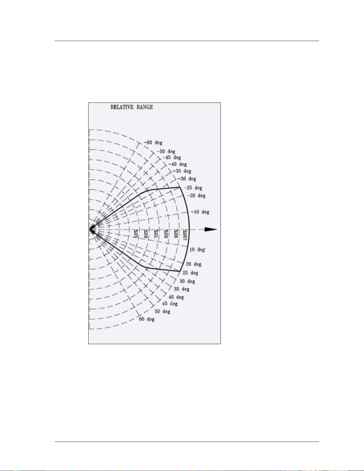
1.5.2 Cone of Vision
1.5.2.1 Gasoline
Horizontal: 67°
Vertical: 70°
Figure 1: Vertical Field of View for Gasoline
Multi IR Hydrocarbon and Hydrogen Flame Detector User Guide
10 Performance Considerations
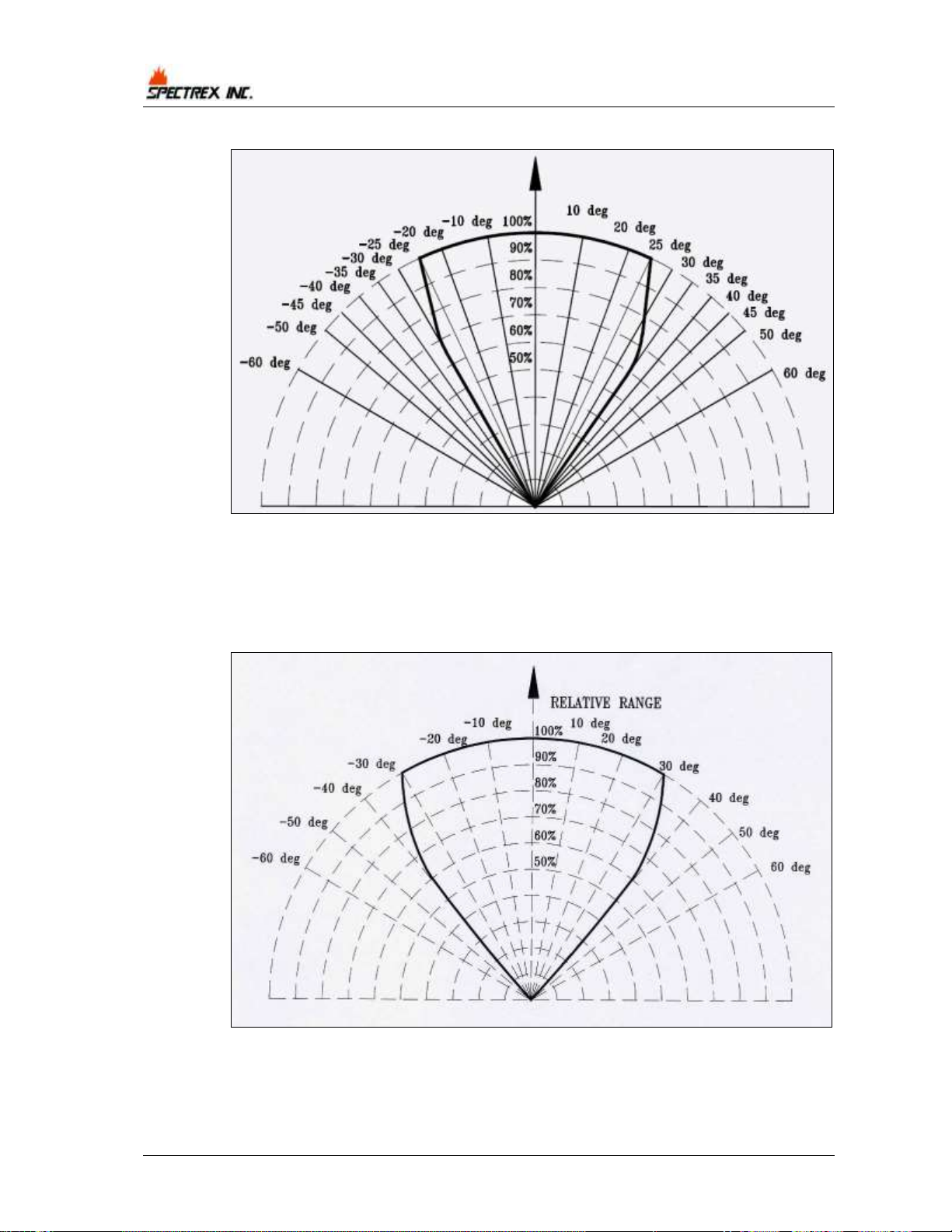
Figure 2: Horizontal Field of View for Gasoline
1.5.2.2 Hydrogen
Horizontal: 80°
Vertical: 80°
Figure 3: Fields of View for Hydrogen (Horizontal and Vertical)

TM 40/40M, Rev (6) July 2013
Performance Considerations 11
1.5.3 False Alarms Prevention
To prevent false alarms, the detector will not alarm or react to the radiation
sources specified in Table 4.
Table 4: Immunity to False Alarm Sources
Radiation Source
Immunity
Distance ft. (m)
Indirect or reflected sunlight
IAD
Vehicle headlights (low beam) conforming to
MS53023-1
IAD
Incandescent frosted glass light, 300 W
IAD
Fluorescent light with white enamel reflector, standard
office or shop, 70 W (or two 35 W)
IAD
Electric arc [12mm (
15
/
32
") gap at 4000 V alternating
current, 60 Hz]
IAD
Arc welding [6 mm (
5
/
16
") rod; 210 A]
See Table 5
Ambient light extremes (darkness to bright light with
snow, water, rain, desert glare and fog)
IAD
Bright colored clothing, including red and safety
orange
IAD
Electronic flash (180 watt-seconds minimum output)
IAD
Movie light, 625 W quartz DWY lamp (Sylvania S.G.-55
or equivalent)
>6.5 (2)
Blue-green dome light conforming to M251073-1
IAD
Flashlight (MX 991/U)
IAD
Radiation heater, 3000 W
>3 (1)
Radiation heater, 1000 W with fan
IAD
Quartz lamp (1000 W)
>3 (1)
Mercury vapor lamp
IAD
Grinding metal
IAD
Lit cigar
>1 (0.3)
Lit cigarette
>1 (0.3)
Match, wood, stick including flare up
>13 (4)
Notes:
IAD = Immune at Any Distance.
All sources are chopped from 0 to 20 Hz.
Multi IR Hydrocarbon and Hydrogen Flame Detector User Guide
12 Performance Considerations
Table 5: Welding Immunity Distance
Sensitivity Setting
Detection Range
Immunity Distance
1
50 ft. (15m)
>6 ft. (2m)
2
100 ft. (30m)
>12 ft. (4m)
3
150 ft. (45m)
>17 ft. (6m)
4
215 ft. (65m)
>25 ft. (7.5m)
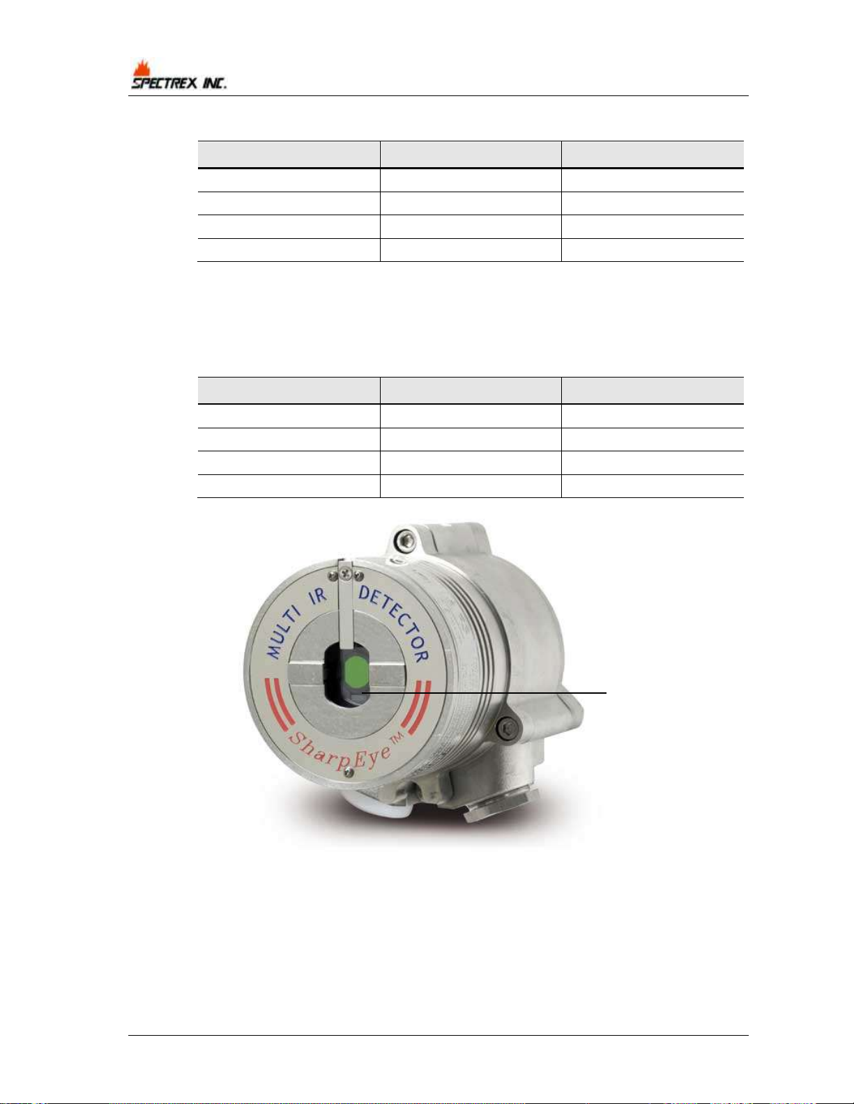
1.5.4 Visual Indicators
One 3-color LED indicator is located inside the detector window, as shown in
Figure 4. The detector statuses are listed in Table 6.
Table 6: LED Indications
Detector Status
LED color
LED mode
Fault, BIT Fault
Yellow
4 Hz - flashing
Normal
Green
1 Hz - flashing
Warning
Red
2 Hz - flashing
Alarm
Red
Steady
Figure 4: Indication LED
Indicator LED
Loading...