


UV/IR Flame Detector
Model 20/20L-LB
User's and Maintenance Manual
TM20/20LB Rev E, August 2004
Factory Mutual Approved |
ATEX Approved |
Class I Div. 1 Groups B, C, D |
Ex II 2G |
Class II Div. 1 Groups E, F, G |
EExd IIB + H2 T5 |
|
EExde IIB + H2 T5 |
218 Little Falls Rd., Cedar Grove, NJ 07009 USA; Phone: +1 (973) 239 8398 Fax: +1 (973) 239 7614 Web-Site: www.spectrex.net; Email: spectrex@spectrex.net
The SharpEye Optical Flame Detector described in this document is the property of Spectrex, Inc.
No part of the hardware, software or documentation may be reproduced, transmitted, transcribed, stored in a retrieval system, or translated into any language or computer language, in any form or by any means, without prior written permission of Spectrex, Inc.
While great efforts have been made to assure the accuracy and clarity of this document, Spectrex, Inc. assumes no liability resulting from any omissions in this document, or from misuse of the information obtained herein. The information in this document has been carefully checked and is believed to be entirely reliable with all of the necessary information included. Spectrex Inc. reserves the right to make changes to any products described herein to improve reliability, function, or design, and reserves the right to revise this document and make changes from time to time in content hereof with no obligation to notify any persons of revisions or changes. Spectrex, Inc. does not assume any liability arising out of the application or any use of any product or circuit described herein; neither does it convey license under its patent rights or the rights of others.
Warning:
This manual should be carefully read by all individuals who have or will have responsibility for using, maintaining or servicing the product.
The Detector is not field-repairable due to the meticulous alignment and calibration of the sensors and the respective circuits. Do not attempt to modify or repair the internal circuits or change their settings, as this will impair the system's performance and void the Spectrex, Inc. Product warranty.
Spectrex Inc. - SharpEyeTM UV/IR Flame Detector |
Manual – TM20/20LB Rev E, August 2004 |
|
|
TABLE OF CONTENT |
|
1. Scope................................................................................................................ |
1 |
|
1.1 |
Product Overview ........................................................................................ |
1 |
1.2 |
Document Overview .................................................................................... |
1 |
2. Technical Description........................................................................................ |
2 |
|
2.1 |
Principles Of Operation ............................................................................... |
2 |
2.2 |
Sensing Elements ....................................................................................... |
2 |
2.3 |
Detection Levels.......................................................................................... |
3 |
2.4 |
Alarm Signal Delay...................................................................................... |
3 |
2.5 |
Built-In-Test (BIT) Capabilities..................................................................... |
3 |
2.6 |
Detector Structure ....................................................................................... |
4 |
2.7 |
System Configuration .................................................................................. |
4 |
2.8 |
Detector Types ............................................................................................ |
4 |
3. Performance ..................................................................................................... |
7 |
|
3.1 |
Detection Sensitivity .................................................................................... |
7 |
3.2 |
Cone Of Vision ............................................................................................ |
9 |
3.3 |
False Alarms ............................................................................................. |
10 |
4. Operation ........................................................................................................ |
11 |
|
4.1 |
Visual Indications ...................................................................................... |
11 |
4.2 |
Output Signals........................................................................................... |
11 |
4.3 |
Mode Selection.......................................................................................... |
12 |
4.3.1 Function switch (SW1)........................................................................ |
12 |
|
4.3.2 Alarm Delay Switch (SW2).................................................................. |
14 |
|
4.4 |
Detector States.......................................................................................... |
15 |
4.5 |
Built-In-Test (refer to 2.5) ......................................................................... |
16 |
5. Technical Specifications ................................................................................. |
18 |
|
5.1 |
Electrical Specifications............................................................................. |
18 |
5.2 |
Mechanical Specifications ......................................................................... |
20 |
5.3 |
Environmental Specifications .................................................................... |
21 |
6. Installation Instructions ................................................................................... |
22 |
|
6.1 |
Introduction................................................................................................ |
22 |
6.2 |
General Considerations............................................................................. |
22 |
6.3 |
Preparations For Installation...................................................................... |
23 |
6.4 |
Conduit Installation.................................................................................... |
23 |
6.5 |
Detector Mounting ..................................................................................... |
24 |
6.5.1 Swivel Mount Kit ................................................................................. |
24 |
|
6.5.2 Swivel installation (Figure 4a and 4b) ................................................. |
24 |
|
6.6 |
Wiring (Refer to Fig. 5) .............................................................................. |
27 |
6.7 |
Terminal Wiring (Figures 6,7) .................................................................... |
28 |
6.8 |
Selection Of Operating Modes .................................................................. |
32 |
7. Operating Instructions..................................................................................... |
33 |
|
7.1 |
Scope ........................................................................................................ |
33 |
7.2 |
Power-Up .................................................................................................. |
33 |
7.3 |
Reset......................................................................................................... |
33 |
7.4 |
Functional Testing ..................................................................................... |
34 |
I
Spectrex Inc. - SharpEyeTM UV/IR Flame Detector |
Manual – TM20/20LB Rev E, August 2004 |
||
7.5 |
Testing With Fire Simulator (See Appendix D) .......................................... |
34 |
|
7.6 |
Safety Precautions .................................................................................... |
|
35 |
8. Maintenance Instructions ................................................................................ |
|
36 |
|
8.1 |
Scope ........................................................................................................ |
|
36 |
8.2 |
Maintenance Instrumentation And Personnel............................................ |
36 |
|
8.3 |
Preventive Maintenance Procedures......................................................... |
|
36 |
8.4 |
Periodic Maintenance Procedures............................................................. |
|
36 |
8.4.1 Power Up Procedure .......................................................................... |
|
36 |
|
8.4.2 Functional Test Procedure.................................................................. |
|
36 |
|
8.5 |
Maintenance Records ............................................................................... |
|
37 |
8.6 |
Troubleshooting......................................................................................... |
|
37 |
8.6.1 Fault Indication ................................................................................... |
|
37 |
|
8.6.2 False Alarm or Warning Indication...................................................... |
|
37 |
|
Appendix A - Wire Selection Tables.................................................................... |
|
39 |
|
Appendix B. Typical Wiring Configurations ......................................................... |
|
41 |
|
Appendix C. Mounting the “EExde approved” version ........................................ |
43 |
||
Appendix D. Long Range UV/IR Fire Simulator .................................................. |
|
47 |
|
II
Spectrex Inc. - SharpEyeTM UV/IR Flame Detector |
Manual – TM20/20LB Rev E, August 2004 |
|
LIST OF FIGURES |
|
|
Figure 1. Flame Detector Assembly - Outline Drawing |
..................................................... |
5 |
Figure 2. Flame Detector Assembly - Schematic Section................................................... |
6 |
|
Figure 3. Horizontal and Vertical Fields of View .............................................................. |
|
9 |
Figure 4.a. U/IR Detector and Swivel Mount Assembly................................................... |
|
25 |
Figure 4.b. Swivel Mount Assembly.................................................................................. |
|
26 |
Figure 5. UV/IR Flame Detector with Cover Removed.................................................... |
|
29 |
Figure 6. Terminal Board Configuration ......................................................................... |
|
30 |
Figure 7. Flame Detector Assembly - Wiring Diagram ................................................... |
|
31 |
Figure 8. Typical Wiring Diagram for Four-Wire Controller ......................................... |
41 |
|
Figure 9. Wiring Diagram for 4-20mA............................................................................. |
|
41 |
Figure 10: Flame Detector Assembly - Wiring Diagram ................................................. |
45 |
|
Figure 11: OPTION A Flame Detector Assembly - Wiring .....Diagram (“de version”) |
46 |
|
Figure 12: OPTION B Flame Detector Assembly - Wiring .....Diagram (“de version”) |
46 |
|
Figure 13: Fire Simulator................................................................................................. |
|
47 |
Figure 14: UV/IR Detector Target Point.......................................................................... |
|
48 |
LIST OF TABLES |
|
|
Table 1. Response Sensitivity Ranges ................................................................................. |
|
8 |
Table 2. Immunity to False Alarm Faults ......................................................................... |
|
10 |
Table 3. LED indications within different detector states ................................................ |
11 |
|
Table 4. Function Switch SW1.......................................................................................... |
|
12 |
Table 5. SW2 Alarm Delay Setting ................................................................................... |
|
14 |
Table 6. Output Signals Versus Detector State................................................................. |
|
15 |
Table 7. Dry Contacts Relays Ratings .............................................................................. |
|
19 |
Table 8: Mounting according to US Version.................................................................... |
|
24 |
Table 9: Mounting according to EU Version ................................................................... |
|
24 |
Table 10. Maximum DC resistance at 68°F for copper wire............................................ |
39 |
|
Table 11. Wiring length in feet (meter)............................................................................. |
|
39 |
Table 12. Terminals wiring options of the detector.......................................................... |
|
46 |
III
Spectrex Inc. - SharpEyeTM UV/IR Flame Detector |
Manual – TM20/20LB Rev E, August 2004 |
IV
Spectrex Inc. - SharpEyeTM UV/IR Flame Detector |
Manual – TM20/20LB Rev E, August 2004 |
1. Scope
1.1 Product Overview
The Spectrex Model 20/20L, 20/20LB is a UV-IR Flame Detector. It is designed to sense the occurrence of fire and flames and subsequently activate an alarm or an extinguishing system directly or through a control circuit for maximum fire protection. It uses innovative technology of advanced digital signal processing to analyze the dynamic characteristics of fire.
The difference between the Models is that Model 20/20LB includes a Built In Test (BIT) function while the model 20/20L does not.
Detection performance is controlled by a microprocessor and easily adapted to all environments, applications and requirements. The result is a unique and superior flame detector that provides excellent detection sensitivity with extreme immunity to false alarm.
1.2 Document Overview
This manual describes the detector and its features. It describes instructions on the installation, operation and maintenance.
This manual is divided into several parts. Each part is contained in a separate chapter as follows:
Chapter 1. Scope. A general introduction and overview of the product and the Manual with a brief description of its content.
Chapter 2. Technical Description - the detector’s theory of operation. Chapter 3. Performance - the detector features and capabilities. Chapter 4. Operation modes, user interface and indications.
Chapter 5. Technical Specifications Detector’s electrical, mechanical and environmental specifications.
Chapter 6. Installation Instructions including wiring and mode setting. Chapter 7. Operating Instructions and power-up procedures. Chapter 8. Maintenance Instructions and support procedures.
Appendix A. Wiring Selection Tables for electrical wire selection according to installation configuration.
Appendix B. Typical Wiring Configurations provides wiring diagrams for installation.
Appendix C. Mounting the “EExde approved” version Appendix D. Long Range UV/IR Fire Simulator
1
Spectrex Inc. - SharpEyeTM UV/IR Flame Detector |
Manual – TM20/20LB Rev E, August 2004 |
2.Technical Description
•Detection Range: Up to 50 ft (15m) for a 1ft x 1ft (0.3m x 0.3m) Gasoline fire.
•Ultra High Immunity to False Alarm (see section. 3.3.).
•Advanced Digital Processing of the Dynamic Characteristics of Fire:
Flickering and threshold
•Dual Spectrum: UV and IR radiation
•Multiple Detection Levels: Warning, alarm and saturated signal
•Solar Blind
•Microprocessor Based: Microcontroller performs signal processing
•Built-In-Test: Manual and automatic BIT for 20/20LB only (see section 4.5)
•Electrical Interface:
o Dry contact RELAYS.
o4-20mA outputs.
2.1Principles Of Operation
The Model 20/20L, 20/20LB Radiation Flame Detector is an electronic device designed to sense the occurrence of fire and flames and subsequently activate an alarm or an extinguishing system directly or through a control circuit.
The UV-IR Radiation Flame Detector is a dual spectrum optical detector sensitive to two separate ranges of the radiation spectrum, both of which are present in fires. The detector monitors the protected volume, by measuring the radiation intensity in it, within two frequencies ranges of the electromagnetic spectrum, namely the Ultra-Violet (UV) and the Infra-Red (IR).
The detector integrates two dependent channels in which appropriate detection pulses are registered and further analyzed for frequency, intensity and duration.
2.2 Sensing Elements
The IR sensor is sensitive to radiation over the range of 2.5-3.0 micron. The IR channel will register a detection signal, at the appropriate level, when the IR sensor is exposed to radiation in the appropriate frequency range, having an intermittent gleam pattern characteristic to flickering-fire, and a preset threshold and time duration are reached.
The UV sensor is sensitive to radiation over the range of 0.185-0.260 micron. The UV channel incorporates a special logic circuit that eliminates false alarms caused by solar radiation and other non-fire UV sources. Further more; the UV channel sensitivity is stabilized over the working temperature range.
2
Spectrex Inc. - SharpEyeTM UV/IR Flame Detector |
Manual – TM20/20LB Rev E, August 2004 |
2.3 Detection Levels
Simultaneous detection of radiation in both the UV and the IR channels having an intensity, which exceeds detector’s preset Warning level, will result in a Warning signal.
In addition, the detector includes an option that detection of UV radiation at high intensity will result in a Warning Signal.
Simultaneous detection of radiation in both the UV and the IR channels having an intensity, which exceeds detector’s preset Alarm level, will result in an Alarm signal.
Simultaneous detection of radiation in both the UV and the IR channels having an intensity which exceeds detector’s preset Flash-Fire Detection level will result in an immediate Alarm signal, regardless of the detector mode setting selected.
Since the preset dual range and level of radiation, as well as the flickering pattern, are characteristic of real fire, all other radiation sources apart from actual fire will not be detected, thus avoiding false alarms.
2.4 Alarm Signal Delay
The detector is adapted with an Alarm Signal delay selector, allowing the user to set a different delay between 0 to 30 seconds, mandatory for several specific applications.
When Alarm level detection conditions are met, an internal time delay is initiated as preset on the selector. Once the preset time delay has elapsed, detection conditions are evaluated for 3 seconds. If during that evaluation period Alarm level detection conditions persist, the Alarm signal is triggered. If no Alarm level detection conditions endure, the Alarm signal Delay is reset.
2.5 Built-In-Test (BIT) Capabilities
The detector (only 20/20LB) is adapted with Built-In-Test (BIT) capabilities. The BIT is continuously performs at predetermined time intervals averaging 60 minutes. It performs automatic full-featured test of the detector’s internal electric circuits, and checks the radiation sensors and the detector window’s cleanliness.
The BIT circuits will generate response signals to indicate satisfactory operation of the detector or a fault should it be detected during a BIT sequence. The BIT sequence can also be initiated manually by the user at his preference, upon a remote operation from a control unit.
3
Spectrex Inc. - SharpEyeTM UV/IR Flame Detector |
Manual – TM20/20LB Rev E, August 2004 |
2.6 Detector Structure
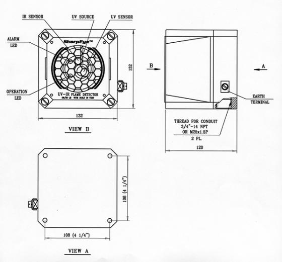
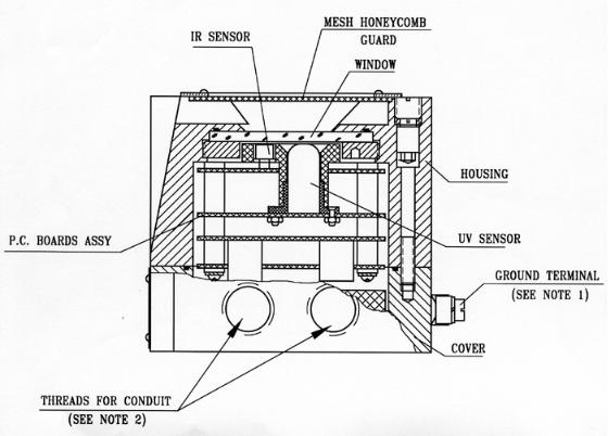
Figure 1 presents an outline drawing of the Flame Detector Assembly. Figure 2 presents a schematic section of the internal Flame Detector, and describes its main components.
2.7 System Configuration
The Spectrex model 20/20L, 20/20LB is a self-contained Optical Flame Detector that can function as a stand alone unit directly connected to external devices as alarm systems or automatic fire extinguishing systems. The same detector can form part of a more complex system where a plurality of detectors and other devices are integrated through a dedicated control unit.
2.8 Detector Types
This manual covers two types of detectors. Model 20/20LB and model 20/20L, the difference is that Model 20/20LB includes a BIT and 20/20L does not include this feature.
Both models are available in either Aluminum (Al.) housing, or Stainless Steel (St.St.) housing.
There is an option for higher ambient temperature 185°F (+85°C) version if specified.
4
Spectrex Inc. - SharpEyeTM UV/IR Flame Detector |
Manual – TM20/20LB Rev E, August 2004 |
|
|
|
|
Figure 1. Flame Detector Assembly - Outline Drawing
5
Spectrex Inc. - SharpEyeTM UV/IR Flame Detector |
Manual – TM20/20LB Rev E, August 2004 |
|
|
|
|
Figure 2. Flame Detector Assembly - Schematic Section
Note 1: This figure describes the Detector, which includes Ground Terminal for ATEX installation. For FM installation device, which includes 1/4” thread for external grounding screw mounting.
Note 2: Conduit/cable entries - standard size is 3/4”-14NPT or M25 as specified at time of order
6

Spectrex Inc. - SharpEyeTM UV/IR Flame Detector |
Manual – TM20/20LB Rev E, August 2004 |
3. Performance
3.1 Detection Sensitivity
Detection sensitivity is the maximum distance at which the detector will reliably detect a specific size of fire & typical type of fuel (standard fire).
Standard Fire:
Standard fire is defined as a 1ft x 1ft (0.3m x 0.3m) Gasoline pan fire with max. Wind speed of 6.5ft/sec (2m/sec).
Sensitivity Ranges:
The detector has three response levels:
1.Warning (Pre-alarm)
2.Alarm
3.Saturated Signal
For some typical ambient conditions the Zeta parameter as defined in NFPA 72 for the detector is 0.01 (1/meter).
Note:
Zeta parameters may vary significantly with changes in temp, air pressure, humidity, visibility conditions, etc.
Response Time:
The typical response time of the detector is 3 seconds for 1 sq. ft. gasoline fire, and 20 msecs for saturated signal, which is defined as a 5” diameter Gasoline fire from a distance of 12”.
7
Spectrex Inc. - SharpEyeTM UV/IR Flame Detector |
Manual – TM20/20LB Rev E, August 2004 |
Other Fuels:
The Detector will react to other fuels in standard fire conditions at maximum response time of 3 seconds.
The sensitivity range to other fuels varies according to the fuel type. Table 1 below provides the sensitivity to other fuels relative to (as a percentage of) the sensitivity to a standard gasoline fire source.
Table 1. Response Sensitivity Ranges
Type of Fuel |
% of Max. Distance at Each |
|
Sensitivity Range |
Gasoline |
100% |
N-Heptane |
100% |
Alcohol 95% |
75% |
JP4 |
75% |
Kerosene |
75% |
Diesel Fuel |
75% |
Methane Fire* |
30% |
Propane Fire* |
30% |
* 0.5m plume fire
8

Spectrex Inc. - SharpEyeTM UV/IR Flame Detector |
Manual – TM20/20LB Rev E, August 2004 |
3.2 Cone Of Vision
Horizontal: 90°
Vertical: 90°
Figure 3 illustrates the relative range as a function of the incidence angle.
Figure 3. Horizontal and Vertical Fields of View
9
Spectrex Inc. - SharpEyeTM UV/IR Flame Detector |
Manual – TM20/20LB Rev E, August 2004 |
3.3 False Alarms
The detector does not provide an alarm or a warning signal as a reaction to the radiation sources specified at Table 2 below.
Notes:
IAD = Immune at any distance.
All sources are chopped from 0 to 20 Hz.
Table 2. Immunity to False Alarm Faults
Radiation Source |
Immunity |
|
Distance ft. (m) |
Sunlight |
IAD |
Indirect or reflected sunlight |
IAD |
Vehicle headlights (low beam) conforming to MS53023-1 |
IAD |
Incandescent frosted glass light, 100W |
IAD |
Incandescent clear glass light, rough service, 100W |
IAD |
Fluorescent light with white enamel reflector, standard office |
IAD |
or shop, 40W (or two 20W) |
|
Arc welding [4mm (5/32in) rod; 240A] |
9.8ft (3m) |
Bright colored clothing, including red and safety orange |
IAD |
Electronic flash (180 watt seconds minimum output) |
IAD |
Red dome light conforming to M251073-1 |
IAD |
Blue-green dome light conforming to M251073-1 |
IAD |
Flashlight (Mx 991/U) |
IAD |
Radiation heater, 1500W |
IAD |
Radiation heater, 1000W with fan |
IAD |
Grinding metal |
3.3ft (1m) |
Lit cigar or cigarette |
IAD |
Match, wood, stick including flare up |
3.3ft (1m) |
10
 Loading...