


20-20SI
Triple IR (IR3) Flame Detector
Model 20/20I
User's and Maintenance Manual
TM 20/20I, Rev. (6) August 2004
Factory Mutual
Approved
Class I Div. 1
Groups B, C, D
Class II Div. 1
Groups E, F, G
ATEX Approved
Ex II 2G
EExd IIB + H
EExde IIB + H
218 Little Falls Rd., Cedar Grove, NJ 07009 USA;
Phone: +1 (973) 239 8398 Fax: +1 (973) 239 7614
Web-Site: www.spectrex.net
T5
2
2
T5
C.S.A. Approved
Class I Groups B, C, D
Class II Groups E, F, G
; Email: spectrex@spectrex.net
S.A.A Approved
Class 1 Zone 1 Exd IIB T5


The SharpEye Optical Flame Detector described in this document is the property
of Spectrex, Inc.
No part of the hardware, software or documentation may be reproduced,
transmitted, transcribed, stored in a retrieval system, or translated into any
language or computer language, in any form or by any means, without prior
written permission of Spectrex, Inc.
While great efforts have been made to assure the accuracy and clarity of this
document, Spectrex, Inc. assumes no liability resulting from any omissions in this
document, or from misuse of the information obtained herein. The information in
this document has been carefully checked and is believed to be entirely reliable
with all of the necessary information included. Spectrex Inc. reserves the right to
make changes to any products described herein to improve reliability, function, or
design, and reserves the right to revise this document and make changes from
time to time in content hereof with no obligation to notify any persons of revisions
or changes. Spectrex, Inc. does not assume any liability arising out of the
application or any use of any product or circuit described herein; neither does it
convey license under its patent rights or the rights of others.
Warning:
This manual should be carefully read by all individuals who have or will have
responsibility for using, maintaining or servicing the product.
The Detector is not field-repairable due to the meticulous alignment and
calibration of the sensors and the respective circuits. Do not attempt to modify or
repair the internal circuits or change their settings, as this will impair the system's
performance and void the Spectrex, Inc. Product warranty.


Spectrex Inc. - SharpEye
TM
IR3 Flame Detector Manual – TM 20/20I, Rev. (6) August 2004
T
ABLE OF CONTENTS
1. Scope ....................................................................................................1
RODUCT OVERVIEW .....................................................................................1
1.1 P
OCUMENT OVERVIEW...................................................................................1
1.2 D
2. Technical Description..........................................................................2
RINCIPLES OF OPERATION............................................................................2
2.1 P
2.1.1 Hydrocarbon fire detection....................................................................2
2.1.2 Identifying the CO
peak.......................................................................2
2
2.1.3 The limitations of IR-IR flame detectors................................................2
2.1.4 The advantages of IR3 technology .......................................................2
3. Performance .........................................................................................5
ETECTION SENSITIVITY.................................................................................5
3.1 D
ONE OF VISION ...........................................................................................7
3.2 C
ALSE ALARMS PREVENTION ..........................................................................8
3.3 F
4. Operation..............................................................................................9
ISUAL INDICATIONS ...................................................................................... 9
4.1 V
4.2 O
UTPUT SIGNALS ........................................................................................10
4.2.1 Optional latching.................................................................................11
4.2.2 Built-In-Test (BIT) ...............................................................................11
4.2.3 Accessory Relay as EOL....................................................................11
MODE SELECTION ........................................................................................11
4.3
4.3.1 Function switch (SW1):.......................................................................12
4.3.2 Address switch (SW2) (Optional):.......................................................13
4.3.3 Alarm Delay switch (SW3):.................................................................14
UILT IN TEST ............................................................................................. 15
4.4 B
5.Technical Specifications.....................................................................18
LECTRICAL SPECIFICATIONS .......................................................................18
5.1 E
ECHANICAL SPECIFICATIONS ......................................................................21
5.2 M
NVIRONMENTAL SPECIFICATIONS.................................................................22
5.3 E
6. Installation Instructions.....................................................................23
COPE........................................................................................................23
6.1 S
6.2 G
ENERAL CONSIDERATIONS ......................................................................... 23
REPARATIONS FOR INSTALLATION................................................................24
6.3 P
ONDUIT INSTALLATION................................................................................24
6.4 C
6.5 D
ETECTOR MOUNTING .................................................................................25
6.5.1 Swivel Mount Kit:.... ... .. .. .. .. .. ... .. .. .. .. .. ... .......................... .. .. .. .. ... .. .. .. ....25
6.5.2 Swivel installation (Figs. No. 8 and 9):................................................25
6.6 W
6.7 T
6.8 M
IRING (REFER TO FIG. 12) .........................................................................28
ERMINAL WIRING (SEE FIG. NO.10 AND NO.11.)...........................................29
ODE SELECTION........................................................................................33
7. Operating Instructions......................................................................34
COPE........................................................................................................34
7.1 S
7.2 P
OWER-UP .................................................................................................34
ESET ........................................................................................................34
7.3 R
UNCTIONAL TESTING................................................................................... 34
7.4 F
I

Spectrex Inc. - SharpEye
TM
IR3 Flame Detector Manual – TM 20/20I, Rev. (6) August 2004
7.4.1 Manual BIT Test .................................................................................35
7.4.2 Testing with fire simulator...................................................................35
7.5 S
AFETY PRECAUTIONS ................................................................................. 36
8. Maintenance Instructions..................................................................37
COPE........................................................................................................37
8.1 S
AINTENANCE INSTRUMENTATION AND PERSONNEL .......................................37
8.2 M
8.3 P
REVENTIVE MAINTENANCE PROCEDURES.....................................................37
ERIODIC MAINTENANCE PROCEDURES.........................................................37
8.4 P
8.4.1 Power-Up Procedure ..........................................................................37
8.4.2 Functional Test Procedure..................................................................37
AINTENANCE RECORDS..............................................................................38
8.5 M
ROUBLESHOOTING .....................................................................................38
8.6 T
8.6.1 Fault Indication ...................................................................................38
8.6.2 False Alarm or Warning Indication......................................................38
Appendix A - Wire Selection Tables..................................................... 39
Appendix B – Typical Wiring Configurations.......................................41
Appendix C – RS-485 Communication Network ..................................45
Appendix D - Mounting the “EExde approved” version......................47
Appendix E - Long Range IR3 Fire Simulator. .....................................51
II

Spectrex Inc. - SharpEye
TM
IR3 Flame Detector Manual – TM 20/20I, Rev. (6) August 2004
L
IST OF FIGURES
Figure 1: IR3 Flame Detector............................................................................................3
Figure 2: Flame Detector Assembly - Outline Drawing ....................................................4
Figure 3: Horizontal and Vertical Fields of View................................................ ..... ..... ... .7
Figure 4: Indication LEDs.............................................................................. ....................9
Figure 5: Switch Locations................................... ..... ... ..... ..... ... ..... ...... .. ...... ..... ... ..... ..... ..15
Figure 6: Electrical Interface............... ..... ... ..... ..... ... ..... ...... .. ...... ..... ..... ... ..... ...... .. ...... ....19
Figure 7: Flame Detector Assembly - Schematic Section ............................ .. ... ............... 20
Figure 8: IR3 Detector and Swivel Mount Assembly.................... .. ..................................26
Figure 9: Swivel Mount Assembly - Outline Drawing......................................................27
Figure 10: Terminal Board........................................ ..... ...... .. ...... ..... ... ..... ..... ... ..... ... ..... ..30
Figure 11: Flame Detector Assembly - Wiring Diagram.................................................31
Figure 12: IR3 Flame Detector with cover removed........................................................32
Figure 13: Flame Detector Wiring Diagram..................... ..... ...... .. ...... ..... ... ..... ..... ... ..... ..41
Figure 14: Typical wiring diagram for 4 wire controllers..................................... ... ....... 42
Figure 15: Typical wiring diagram for controllers with alarm & fault loops ..................43
Figure 16: 4-20mA wiring.............................. ...... .. ...... ..... ... ..... ..... ... ..... ... ..... ...... .. ...... ....44
Figure 17: RS-485 networking...................... ..... ... ..... ..... ... ..... ...... .. ...... ..... ... ..... ..... ... ..... ..45
Figure 18: Flame Detector Assembly - Wiring Diagram.................................................49
Figure 19: OPTION A Flame Detector Assembly - Wiring Diagram (“de version”).....50
Figure 20: OPTION B Flame Detector Assembly - Wiring Diagram (“de version”).....50
Figure 21: Fire Simulator............................................................................................... ..51
Figure 22: IR3 Detector Target Point.................. ............................................................52
IST OF TABLES
L
Table 1: Alarm Response Time Versus Range.................................................................... 5
Table 2: Response Sensitivity Ranges........................................................... .. ....................6
Table 3: Immunity To False Alarm Sources.......................................................................8
Table 4: Welding Immunity Distance ..................................................... ... .........................8
Table 5: Output Signals Versus Detector State ................................................................10
Table 6: Function Switch SW1........................................ ... ................................... ............ 12
Table 7: Sensitivity range ............................................. .. ................................... ... ............ 12
Table 8: Address Switches SW2................................. ................................... ....................13
Table 9: SW2 Address Setting............................................... .................................. .......... 13
Table 10: SW3 Alarm Delay Setting.......... ................................... .................................. ..14
Table 11: Contact Ratings...................... ................................... ................................... .... 20
Table 12: Mounting according to US Version................................ ... ...............................25
Table 13: Mounting according to EU Version ....................................................... .......... 25
Table 14: Maximum DC resistance at 68˚F for copper wire............................................39
Table 15. Wiring length in feet (meter)...................................................................... ....... 39
III

Spectrex Inc. - SharpEye
TM
IR3 Flame Detector Manual – TM 20/20I, Rev. (6) August 2004
IV

Spectrex Inc. - SharpEyeTM IR3 Flame Detector Manual – TM 20 /20I, Rev. (6) August 2004
1. Scope
1.1 Product Overview
The Spectrex Model 20/20I is a triple IR spectrum flame detector designed to
provide maximum fire protection. It uses innovative technology of advanced digital
signal processing to analyze the dynamic characteristics of fire. Three sensitive IR
channels process the signals. Detection performance is controlled by a
microprocessor and easily adapted to all environments, applications and
requirements. The result is a unique and superior flame detector, which provides
excellent detection sensitivity with extreme immunity to false alarm.
1.2 Document Overview
This manual describes the detector and its features and provides instructions on
the installation, operation and maintenance.
This manual is divided into separate chapters as follows:
Chapter 1. Scope - a general introduction and overview of the product and the
Manual, with a brief description of its content.
Chapter 2. Technical Description - the detector’s theory of operation.
Chapter 3. Performance - the detector features and capabilities.
Chapter 4.
Chapter 5. Technical Specifications - the Detector’s electrical, mechanical and
Chapter 6. Installation Instructions, including wiring and mode setting.
Chapter 7. Operating Instructions and power-up procedures.
Chapter 8. Maintenance Instructions and support procedures.
Appendix A. Wiring Selection Tables for electrical wire selection according
Appendix B. Typical Wiring Configurations - wiring diagrams for
Appendix C. RS-485 Communication Network
Appendix D.
Appendix E. Long Range IR3 Fire Simulator
Operation
indications.
environmental specifications.
to installation configuration.
installation.
Mounting the “EExde approved” version
- the detector’s operation modes, user interface and
1

Spectrex Inc. - SharpEyeTM IR3 Flame Detector Manual – TM 20 /20I, Rev. (6) August 2004
2. Technical Description
•
Detection Range: up to 200 ft (60m) for a 1ft x 1ft (0.3m x 0.3m) fire.
• Ultra High Immunity to False Alarms (see section. 3.3).
• Advanced Digital Processing of the Dynamic Characteristics of Fire:
Flickering, Threshold correlation and Ratio.
• Three Separate IR Channels: Between 3-5 microns.
•
Field Programmable Sensitivity: four ranges.
•
Two Response Levels: Warning & Detection.
• Solar Blind
•
Microprocessor Based
•
Built In Test: Manual and Automatic (see section. 4.2.2).
• Electrical Interface:
o Dry contact RELAYS.
Communication network RS-485.
o
4-20mA output.
o
• Certification: Approved by F.M, CSA, ATEX.
: Digital signal processing.
2.1 Principles Of Operation
2.1.1 Hydrocarbon fire detection
The triple IR flame detector detects all conceivable types of hydrocarbon fires, i.e.
any fire, which emits CO
2.1.2 Identifying the CO
The hydrocarbon fire is characterized by a typical radiation emission. The CO
.
2
peak
2
2
peak emits intense radiation in the spectral band between 4.2 µ - 4.5 µ and
weaker radiation intensity outside this spectral band.
2.1.3 The limitations of IR-IR flame detectors
in the atmosphere attenuates the radiation in this spectral band. (Absorption
CO
2
and emission of radiation always occur in the same band.) As a result, the greater
the distance between the detector and the fire, the weaker the intensity of the
radiation reaching the detector (the CO
attenuation increases). This phenomenon
2
explains the limitations of the existing IR-IR flame detectors in the market:
• Detection distance is restricted to 33ft (10m) only.
•
Their immunity to false alarm sources is limited.
2.1.4 The advantages of IR3 technology
To overcome these limitations, Spectrex Inc. revised an innovative concept of
utilizing an additional detection channel. Three channels collect more data from
the environment, permitting more accurate analysis and better performance.
2

Spectrex Inc. - SharpEyeTM IR3 Flame Detector Manual – TM 20 /20I, Rev. (6) August 2004
After careful investigation, three channels were selected which, when operating
jointly, provide optimal fire detection characteristics:
Channel 1: 4.2 µ - 4.6 µ
Fire - the CO
peak
2
Channel 2: 4.0 µ - 4.2 µ
Eliminates false alarms from high temperature sources.
Channel 3: 4.8 µ - 5.2 µ
Eliminates false alarms from flickering of background radiation.
Most IR sources, which create misleading IR alarm stimuli, including the sun,
incandescent and halogen lamps, electric arc discharges, electrical heaters, etc.,
do not possess this unique spectral signature of fire. The IR sensors of the
detector respond only to flickering of radiation signals. The signals are compared
to a predetermined threshold. Processing of the results from the three IR channels
is performed by the board microprocessor. The result is a much greater detection
distance and a highly increased ability to distinguish between fire and false alarms.
This sophisticated technology surpasses all other existing flame detection
techniques on the market today.
This unique flame analysis capability (patent pending) has been
incorporated into the Triple-IR fire detector manufactured by Spectrex, Inc.
The result is a unique flame detector, which does not produce false alarms
and provides at the same time detection over greatly increased distances.
Figure 1: IR3 Flame Detector
3

Spectrex Inc. - SharpEyeTM IR3 Flame Detector Manual – TM 20 /20I, Rev. (6) August 2004
Figure 2: Flame Detector Assembly - Outline Drawing
4

Spectrex Inc. - SharpEyeTM IR3 Flame Detector Manual – TM 20 /20I, Rev. (6) August 2004
3. Performance
3.1 Detection Sensitivity
Detection sensitivity is the maximum distance at which the detector will reliably
detect a specific size of fire & typical type of fuel (standard fire).
Standard Fire:
A 1ft x 1ft (0.3m x 0.3m) Gasoline pan fire with max. wind speed of 6.5 ft/sec
(2 m/sec).
Sensitivity Ranges:
The detector has four user selectable sensitivity ranges. For each range there are
two response levels.
1. WARNING (Pre-alarm)
2. ALARM
The detection distance, for the WARNING level, is approximately 10% higher than
the ALARM distance. Alarm response times for a “standard fire” at a specified
range are shown hereunder.
Table 1: Alarm Response Time Versus Range
Sensitivity 1 2 3 4
Range – ft (m) 50 (15) 100 (30) 150 (45) 200 (60)
Response Time (sec) 3 5 8 10
For some typical ambient conditions the Zeta parameter as defined in NFPA 72 for
the detector is 0.005 (1/meter).
Note:
Zeta parameters may vary significantly with changes in temp, air pressure,
humidity, visibility conditions, etc.
5

Spectrex Inc. - SharpEyeTM IR3 Flame Detector Manual – TM 20 /20I, Rev. (6) August 2004
Other fuels
The detector will react to other types of fires as follows:
Pan Fire Size: 1ft x 1ft (0.3m x 0.3m)
Maximum Wind Speed: 6.5 ft/sec (2 m/sec)
Maximum Response Time: 10 sec
Table 2: Response Sensitivity Ranges
Type Of Fuel % Of Max. Distance at
Each Sensitivity Range
Gasoline 100%
N-Heptane 100%
Alcohol 95% 75%
JP4 75%
Kerosene 75%
Diesel Fuel 70%
Methane* 30%
Propane* 30%
* 0.5m plume fire
6
Spectrex Inc. - SharpEyeTM IR3 Flame Detector Manual – TM 20 /20I, Rev. (6) August 2004
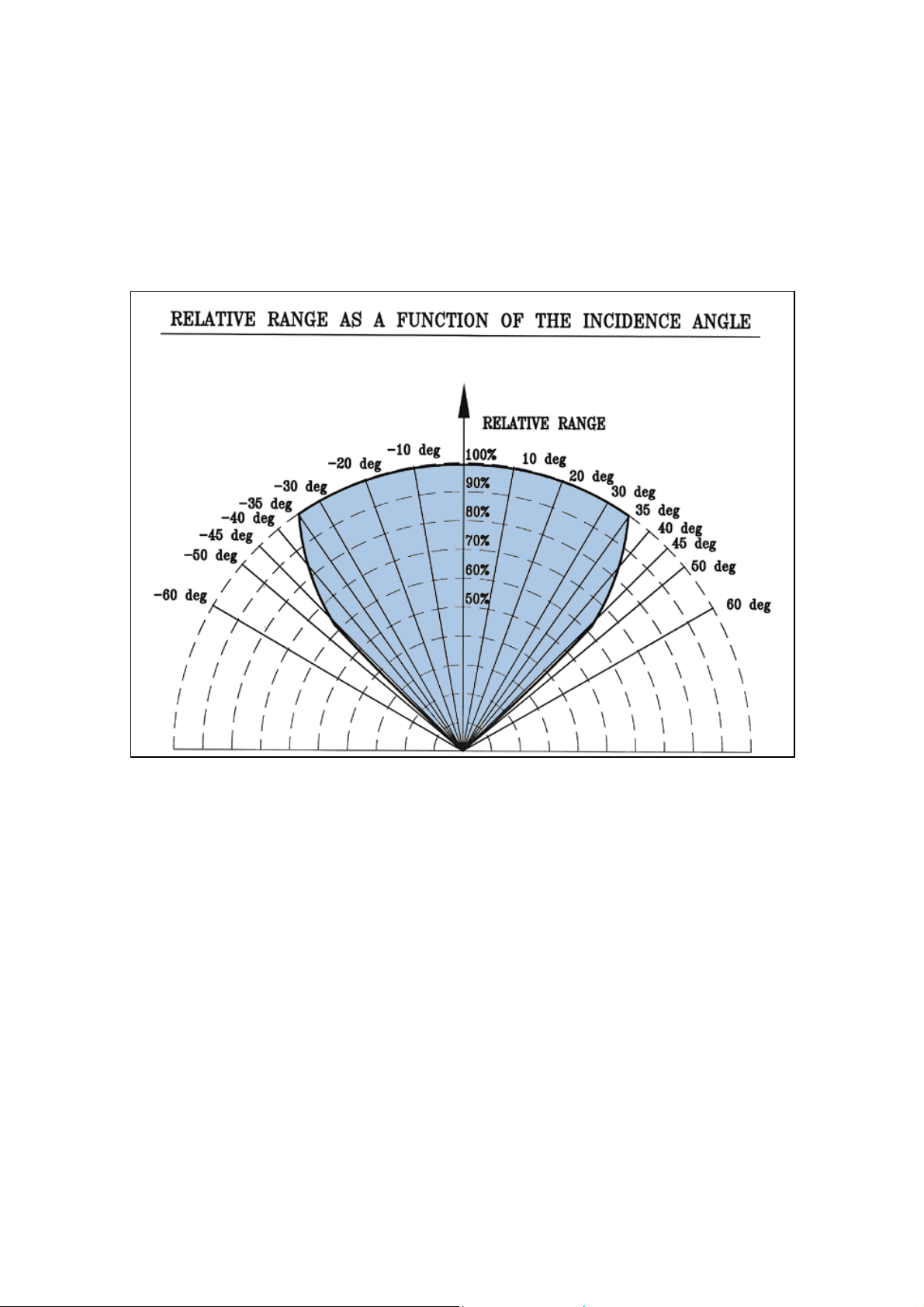
3.2 Cone Of Vision
Horizontal: 90°
Vertical: 90°
Figure 3: Horizontal and Vertical Fields of View
7

Spectrex Inc. - SharpEyeTM IR3 Flame Detector Manual – TM 20 /20I, Rev. (6) August 2004
3.3 False Alarms Prevention
The detector will not provide an alarm or a warning signal as a reaction to the
radiation sources specified below.
Notes:
IAD = Immune at Any Distance.
All sources are chopped from 0 to 20Hz.
Table 3: Immunity To False Alarm Sources
Radiation Source Immunity
Distance ft(m)
Sunlight IAD
Indirect or reflected sunlight IAD
Vehicle headlights (low beam) conforming to MS53023-1 IAD
Vehicle IR lights (low beam) conforming to MS53024-1 IAD
Incandescent frosted glass light, 100 W IAD
Incandescent clear glass light, rough service, 100 W IAD
Fluorescent light with white enamel reflector, standard office or
IAD
shop, 40 W (or two 20 W)
Electric arc [12mm (15/32 in) gap at 4000 V alternating current,
IAD
60 Hz]
Arc welding [4 mm (5/32 in) rod; 240 A] See Table 4
Ambient light extremes (darkness to bright light with snow, water,
IAD
rain, desert glare and fog)
Bright colored clothing, including red and safety orange. IAD
Electronic flash (180 watt-seconds minimum output) IAD
Movie light, 625 W quartz DWY lamp (Sylvania S.G.-55 or
6.5 (2)
equivalent)
Red dome light conforming to MS51073-1 IAD
Blue-green dome light conforming to M251073-1 IAD
Flashlight (MX 991/U) IAD
Radiation heater, 1500 W IAD
Radiation heater, 1000 W with fan IAD
Quartz lamp (1000 W) 10 (3)
Mercury vapor lamp IAD
Grinding metal IAD
Lit cigar 1 (0.3)
Lit cigarette 1 (0.3)
Match, wood, stick including flare up 10 (3)
Table 4: Welding Immunity Distance
SW setting Detection Range Immunity Distance
1 50 ft (15m) >13 ft (4m)
2 100 ft (30m) >20 ft (6m)
3 150 ft (45m) >30 ft (9m)
4 200 ft (60m) >40 ft (12m)
8

Spectrex Inc. - SharpEyeTM IR3 Flame Detector Manual – TM 20 /20I, Rev. (6) August 2004
4. Operation
4.1 Visual Indications
Two LED-indications are located in the detector front window:
i. Power LED (Yellow)
Normal - LED ON
BIT failure - LED blinks (4 Hz)
ii. Alarm LED (Red)
Normal - LED OFF
Warning - LED blinks (2 Hz)
ALARM - LED ON
Figure 4: Indication LEDs
9

Spectrex Inc. - SharpEyeTM IR3 Flame Detector Manual – TM 20 /20I, Rev. (6) August 2004
4.2 Output Signals
The detector controls the following outputs:
•
Alarm relay
• Accessory relay
• Fault relay
•
4-20mA current output
•
RS-485 communication
The detector can be in one of the following states.
Normal: The detector is functioning normally.
BIT: The detector performs a Built-In-Test.
Warning: Fire detected - changed to warning – pre-alarm state.
Alarm: Fire detected - changed to fire alarm state.
Latched Alarm
(Optional)
The alarm outputs are latched due to the detection of a fire that
has already been extinguished.
Fault: A fault is detected during a BIT sequence or the power supply is
too low. In each state the detector will activate different outputs
as specified in table 5.
Table 5: Output Signals Versus Detector State
Detector
State
Normal
Warning Sw1-2 ON On Blink
SW1 Power
Led
Alarm
Led
Alarm
Relay
Accessory
Relay
Fault
Relay
4-20mA
Output
On Off Off Off On 5mA
Off On On 10mA
2Hz
Alarm On On On On On 15mA
Latch Sw1-1 ON On Off On Off On 5mA
Fault Blink
Off Off Off Off 0mA
4Hz
• The detector will be in its FAULT state until it has passed a successful BIT.
•
When SW1-2 is OFF, WARNING state is the same as the ALARM state.
• The alarm outputs will be activated as long as the alarm conditions are present
and will stop approximately 5 seconds after the fire is no longer detected.
10

Spectrex Inc. - SharpEyeTM IR3 Flame Detector Manual – TM 20 /20I, Rev. (6) August 2004
4.2.1 Optional latching
The detector includes a latched alarm output capability, which operates according
to the DIPswitch SW1-1 position. Upon the detection of a fire, the detection signal
is latched until manually reset (disconnecting the power supply or performing a
manual BIT).
4.2.2 Built-In-Test (BIT)
Successful Manual BIT
will activate the following outputs according to SW1
switches.
SW 1-4 ON The ALARM relay will be activated for 3 seconds.
The 4-20mA output will provide 15mA for 3 sec.
SW 1-5 ON & SW 1-4 ON The ACCESSORY & ALARM relays will be
activated for 3 sec.
The 4-20mA output will provide 15mA for 3 sec.
SW 1-5 ON & SW 1-4 OFF The ACCESSORY relay will be activated for
3 sec.
The 4-20mA output will provide 10mA for 3 sec.
4.2.3 Accessory Relay as EOL
When SW1-8 is ON then the accessory relay is used as End of Line relay. In this
case, the accessory relay is active as long as the detector is not in its FAULT
state.
: The detectors’ status is available through its RS-485 communication link.
Note
4.3 Mode Selection
The detector has 3 DIPswitches, which enable the user to adapt the detectors’
operation to specific applications:
• Function switch (SW1)
•
Address switch (SW2) – only if using the RS-485 Serial address
•
Alarm delay switch (SW3)
11
 Loading...