


UL 633
User Guide Bedienungsanleitung Manuel de l´utilisateur Guida per l´uso Gúia del usuario
Gebruikershandleiding Operatörshandbok Brugermanual Guia do Usuário Bruksanvisning
Käyttäjän opas
Instrukcja obsługi
Руководство пользователя
www.trimble.com
d |
f |
c e
b
|
|
h |
a |
i |
g |
|
|
l
i
j
k
|
|
|
|
|
Printed in Germany |
Q104735 Rev. A(01/12) |
|
|
|
|
|

Service and Customer Advice
North-Latin America
Trimble Spectra Precision Division 8261 State Route 235
Dayton, Ohio 45424 U.S.A.
+1 (888) 272-2433 (Toll Free in U.S.A.) +1-937-482-0030 Fax www.trimble.com
www.spectraprecision.com www.spectra-productivity.com
Africa & Middle East
Trimble Export Middle-East P.O. Box 17760
JAFZ View, Dubai UAE
+971-4-881-3005 Phone
+971-4-881-3007 Fax
Europe
Trimble Kaiserslautern GmbH
Am Sportplatz 5
67661 Kaiserslautern
GERMANY
+49-6301-711414 Phone
+49-6301-32213 Fax
Asia-Pacific
Trimble Navigation Singapore PTE Ltd.
80 Marine Parade Road, #22-06
Parkway Parade
Singapore, 449269
+65 6348 2212 Phone
+65 6348 2232 Fax
China
Trimble Beijing
Room 2805-07, Tengda Plaza, No. 168 Xiwai Street
Haidian District Beijing, China 100044
+86 10 8857 7575 Phone
+86 10 8857 7161 Fax www.trimble.com.cn

TABLE OF CONTENTS |
GB |
Introduction |
2 |
FOR YOUR SAFETY |
2 |
COMPONENTS |
2 |
How to use the Laser System |
3 |
Powering the Laser |
3 |
RC603 Radio/IR Remote Control |
3 |
Turning On/Off the RC603 |
3 |
LASER SETUP |
4 |
Turning On/Off the Laser |
4 |
Features and functions |
4 |
Standard Features |
5 |
X-Y-Z-grade entering mode |
5 |
Using the Rotation mode |
6 |
Using the Scan mode |
6 |
Manual mode |
6 |
Special MENU Features |
7 |
Menu Functions (Radio controlled) |
7 |
Menu Functions (IR controlled) |
7 |
Automatic PlaneLok mode |
8 |
Automatic Grade Match |
8 |
Manual Grade Match |
9 |
Automatic Axis Alignment |
9 |
Manual Spot Search mode |
10 |
Activating/Deactivating Standby mode |
10 |
Start Reference Check |
11 |
Centering the Rotor |
11 |
Setting Menu |
11 |
Info |
11 |
Service menu |
11 |
Special Features - Vertical Setup |
12 |
Z-Axis Automatic Spot Align |
12 |
Z-axis Automatic Spot Lok |
13 |
Z-axis Automatic Spot Match |
13 |
Line Scan |
14 |
Beam Plunge |
14 |
Setting menu details |
14 |
Pairing |
14 |
Pairing the transmitter with remote control |
15 |
Pairing the transmitter with receiver |
15 |
Mask mode |
15 |
Grade Entry |
16 |
Grade Display |
16 |
Sensitivity |
16 |
HI-alert selection |
16 |
User Name |
17 |
Set Password |
17 |
Password On/Off |
17 |
Radio RF-Channel) |
17 |
CALIBRATION |
18 |
Checking Calibration of the Y- and X-Axes |
18 |
Checking Calibration of the Z-(vertical) Axis |
18 |
Troubleshooting |
19 |
SF601 Spot Finder User Guide |
20 |
PROTECTING THE UNIT |
23 |
CLEANING AND MAINTENANCE |
23 |
PROTECTING THE ENVIRONMENT |
23 |
WARRANTY |
23 |
TECHNICAL DATA |
24 |
1
Introduction
Thank you for choosing one of the Spectra Precision Lasers from the Trimble family of precision lasers. The universal laser is an easy-to-use tool that offers accurate horizontal, vertical and sloped laser reference up to 1300 ft (400 m) away using a receiver. The plumb beam can be detected automatically and manually using the additional SpotFinder
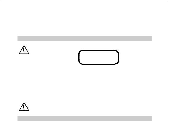
For Your Safety
For hazardless and safe operation, read all the user guide instructions.
LASER RADIATION
AVOID DIRECT EYE
EXPOSURE CLASS 3A/3R
LASER PODUCT
•Use of this product by people other than those trained on this product may result in exposure to hazardous laser light.
•Do not remove warning labels from the unit.
•The UL633 is Class 3A/3R (< 5mW, 600 ... 680 nm).
•Never look into the laser beam or direct it to the eyes of other people.
•Always operate the unit in a way that prevents the beam from getting into people‘s eyes.
•If initial service is required, which results in the removal of the outer protective cover, removal must only be performed by factory-trained personnel.
Caution: Use of other than the described user and calibration tools or other procedures may result in exposure to hazardous laser light.
Caution: Using different than described at the UL633 user guide, may result in unsafe operation.
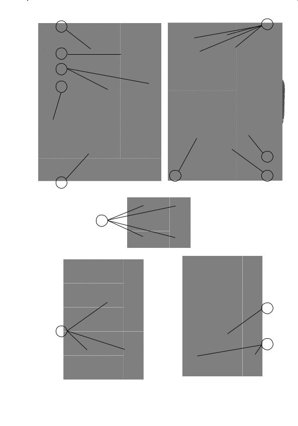
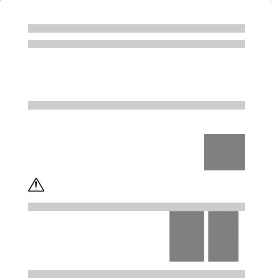
COMPONENTS
aKeypad/LCD-Display
bHandle
cRotor with fan beam lens
dSunshade
eAxes-Alignment-Marks
fSighting Guides/Scope Mounts
gBattery door
hRubber Cover/Recharge Jack
i5/8” x 11 Tripod Mounts
jRubber Feet
kTurnable Legs
lPlus and Minus Battery Diagrams
2
HOW TO USE THE LASER SYSTEM
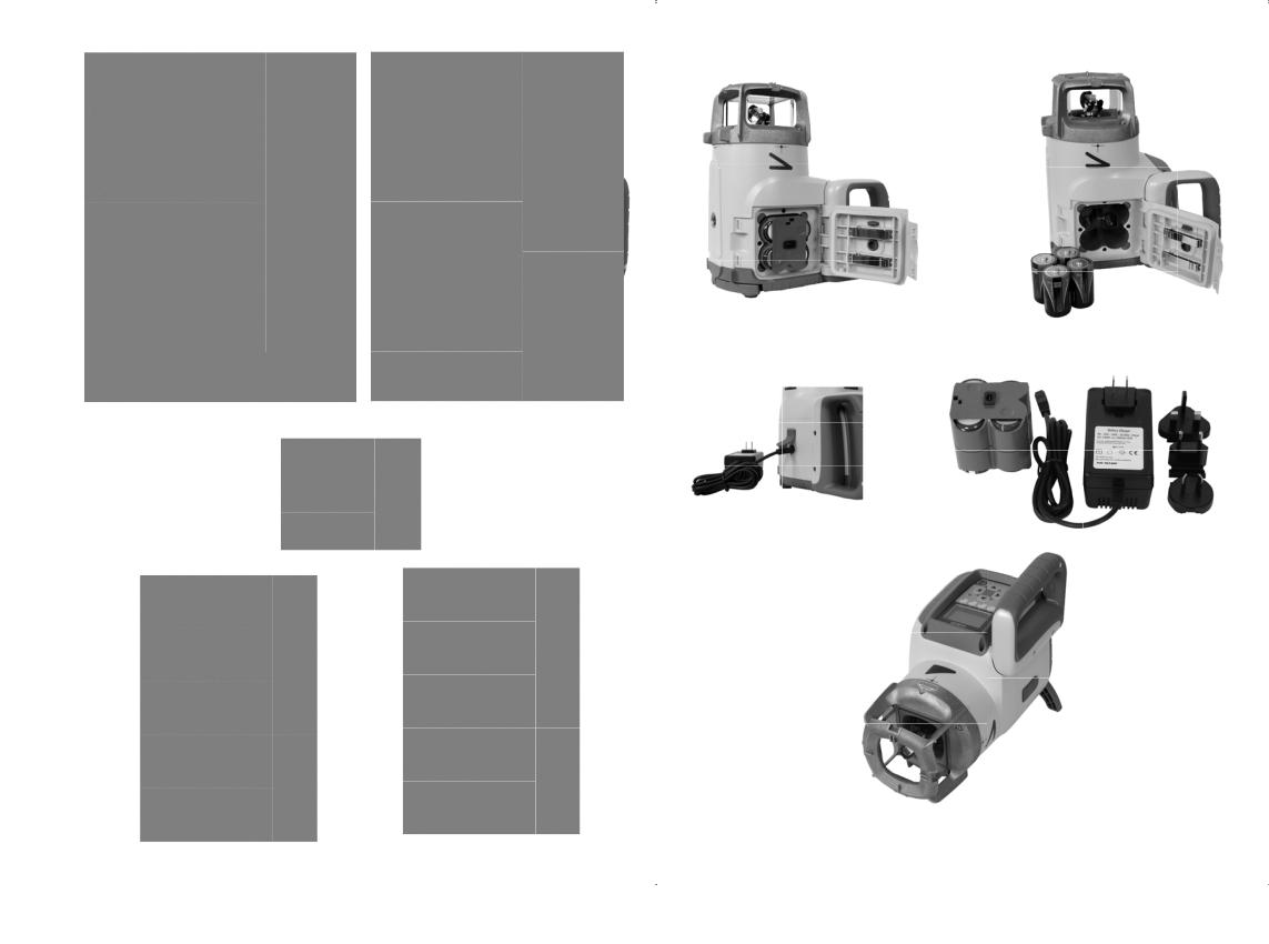
POWERING THE LASER
Batteries
WARNING
Ni-MH batteries may contain small amounts of harmful substances. Be sure to charge the battery before using it for the first time, and after not using it for an extended length of time. Charge only with specified chargers according to device manufacturer‘s instructions. Do not open the battery, dispose of in fire or short circuit; it may ignite, explode, leak or get hot causing personal injury. Dispose in accordance with all applicable federal, state, and local regulations. Keep the battery away from children. If swallowed, do not induce vomiting. Seek medical attention immediately
Recharging the Batteries
The laser is shipped with a rechargeable Ni-MH battery pack.
Note: The approximate charge of the batteries is shown at the left top side of the LCD.
The charger requires approx. 10 hours to charge empty rechargeable batteries.
For charging, connect the plug of the charger to the recharge jack of the battery pack.
New or long-time out-of-use rechargeable batteries reach their best performance after being charged and recharged five times. For Indoor applications the charger can be used as a power supply for the UL.
Alkaline batteries can be used as a backup. Insert 4 D-cell batteries noting the plus
(+) and minus (-) diagrams inside the battery housing.
The batteries should only be charged when the laser is between 50° F and 104° F (10°C to 40°C). Charging at a higher temperature may damage the batteries. Charging at a lower temperature may increase the charge time and decrease the charge capacity, resulting in loss of performance and shortened life expectancy.
RC603 Radio/IR Remote Control
Powering the RC603
1.Open the battery door using a coin or similar pry device to release the battery door tab on the RC603. RC603 will be shipped with alkaline batteries Rechargeable batteries can be used optional but need to be charged externally
2.Insert two AA batteries noting the plus (+) and minus (-) diagrams inside the battery housing.
3.Close the battery door. Push down until it “clicks” into the locked position.
Turning On/Off the Radio/IR Remote Control
The radio/IR remote control is a hand-held device that allows you to send operational commands to the laser from a remote location.
Press the power button to turn on the radio/IR remote control. A “ ” and additional vertical bars appear in the right corner of the remote’s top display line indicating the radio connection status between the laser and the remote control. If the RC603 is outside the radio operating range the remote switches automatically into the IR connection capability.
Note: When the remote control is initially turned on, the standard display (model number and software version) appear for the first 3 seconds, then the axes symbols and last-entered grade for each axis briefly appear in the LCD.
With every button press, the LCD backlight is activated and turns off automatically if no button is pressed for 8 seconds.
To turn off the radio remote control, press and release the power button.
Note: 5 minutes after the last button press, the remote control turns off automatically.
3
LASER SETUP
Position the laser horizontally (tripod mount and rubber feet downward!) on a stable platform, wall mount or tripod at the desired elevation.
The laser recognizes automatically whether it is used horizontally or vertically when switched on.
Turning On/Off the laser
Press the power button to turn On/Off the laser.
Note: Depending on the setup (horizontal or vertical) and if a grade value has been dialed in, the unit starts the temperature/reference check while the thermometer symbol is flashing.
When the temperature/reference check has been finished, the standard display appears and the bubble symbols flash until self-leveling has been completed.
If the self-leveling can’t be finished based on the selected sensitivity, an error message appears.
A bubble symbol helps to adjust the unit at the cross axis when set up vertical for automatic Spot Align or in vertical manual mode.
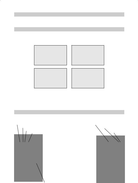
Features and Functions
Standard Display |
|
|
The remote control mirrors the functionality of the UL keypad |
HI alert function is activated |
|
Battery status laser |
||
Mask selection |
Battery Status Remote Control |
|
Rotation speed/Scan angle |
Status Radio Connectivity |
|
Fan Beam is activated |
||
|
Button 1: Quickly press and release starts the MENU entry.
Button 2: Quickly press and release starts the grade entering mode.
Button 3: Quickly press and release activates/ deactivates the manual mode.
Button 4: Quickly press and release to toggle through the pre-selected rotation speeds. Press and hold for three seconds changes the unit into scan mode. When in scan mode, quickly press and release button 4 toggles through the pre-selected scan sizes.
Button 5, 8:up/down arrow buttons. Button 6, 7:left/right arrow buttons.
Button 9: ON/OFF button - press for 1 second to turn on the unit; press and hold for 2 seconds to turn off the unit.
Leveling/Standby – LED (green/red)
4
Standard Features
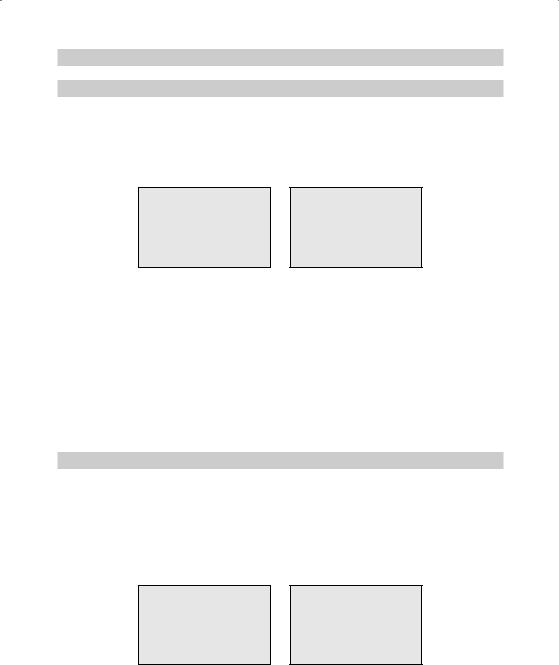
X-Y-Z-grade entering – Step and Go mode
Quickly press and release button 2 starts the grade entering mode. Both grade values will be shown. Press/release button 1 a grade reverse Y
Press/release button 2 a grade reverse X
Press/release button 3 a return to the standard display
Quickly press and release button 4 to confirm the selected grade value and return to the standard display
Press and hold button 6 or 7 (left/right) to change X- axis grade value after the comma; press and hold buttons 6 + 7 simultaneously starts X-axis quick change mode where the grade value in front of the comma will be set to 0% and then starts changing in 1% increments.
Press and hold button 5 or 8 (up/down) for changing Y/Z -axis grade value; press and hold buttons 5 + 8 simultaneously starts Y/Z - axis quick change mode where the grade value in front of the comma will be set to 0% and then starts changing in 1% increments.
Note: The speed of the grade value change increases with the amount of time the button is held down.
Note: The grade value for both axes increases in 1.00% increments. When the grade value for either axis reaches its highest amount, the grade value switches to the lowest value for that axis. For example, the value switches from +25% to -25%.
The laser will self-level to the required grade position after confirming the grade change with button 4.
Note: The bubble symbols at the laser’s LCD will flash until the laser has been self-leveled to the requested grade position.
X-Y-Z-grade entering – Digit Select mode
Quickly press and release button 2 starts the grade entering mode. .
Both grade values will be shown. Press/release button 1 a quick set to 0%
Press/release button 2 a change the sign in front of the grade value Press/release button 3 a return to the standard display.
Quickly press and release button 4 to confirm the selected grade value and return to the standard display.
Press and release button 5 or 8 (down or up) to move the cursor to the X- or Y-axis (not used in Z- mode) Pressing and releasing button 6 or 7 (right or left) moves the cursor to the right/left.
5
 Loading...