


DG711
Table of contents
 Loading...
www.surveyinstrumentsales.com
DG711 and DG511
Pipe Laser
User Guide

F
Version 1.6
Part Number 1281-0100
Revision C
September 2007
DG711 and DG511
Pipe Laser
User Guide

Corporate Office
Trimble Construction Division
5475 Kellenburger Road
Dayton, Ohio 45424-1099
U.S.A.
(800) 538-7800 (Toll Free in U.S.A.)
+1-937-245-5600 Phone
+1-937-233-9004 Fax
www.trimble.com
Copyright and Trademarks
© 2002-2007, Trimble Navigation
Limited. All rights reserved.
The Globe & Triangle logo, and
Trimble are trademarks of Trimble
Navigation Limited.
All other trademarks are the property
of their respective owners.
Release Notice
This is the September 2007 release
(Revision C) of the DG711 and DG511
Pipe Laser User Guide, part number
1281-0100. It applies to version 1.6 of
the DG711 and DG511 Pipe Laser
software.
The following limited warranties give
you specific legal rights. You may have
others, which vary from
state/jurisdiction to state/jurisdiction.
Hardware Limited Warranty
Trimble Navigation Limited warrants
that this hardware product (the
“Product”) will perform substantially
in accordance with published
specifications and be substantially free
of defects in material and
workmanship for a period of one (1)
year (DG511 Pipe Laser) and two (2)
years (DG711 Pipe Laser) starting
from the date of delivery. The warranty
set forth in this paragraph shall not
apply to software products.
Software License, Limited
Warranty
This Trimble software product,
whether provided as a stand-alone
computer software product, built into
hardware circuitry as firmware,
embedded in flash memory, or stored
on magnetic or other media, (the
“Software”) is licensed and not sold,
and its use is governed by the terms of
the relevant End User License
Agreement (“EULA”) included with
the Software. In the absence of a
separate EULA included with the
Software providing different limited
warranty terms, exclusions and
limitations, the following terms and
conditions shall apply. Trimble
warrants that this Trimble Software
product will substantially conform to
Trimble’s applicable published
specifications for the Software for a
period of ninety (90) days, starting
from the date of delivery.
Warranty Remedies
Trimble's sole liability and your
exclusive remedy under the warranties
set forth above shall be, at Trimble’s
option, to repair or replace any Product
or Software that fails to conform to
such warranty ("Nonconforming
Product") or refund the purchase price
paid by you for any such
Nonconforming Product, upon your
return of any Nonconforming Product
to Trimble in accordance with
Trimble’s standard return material
authorization procedures.
Warranty Exclusions and
Disclaimer
These warranties shall be applied only
in the event and to the extent that the
Products and Software are properly
and correctly installed, configured,
interfaced, maintained, stored, and
operated in accordance with Trimble's
relevant operator's manual and
specifications, and; (ii) the Products
and Software are not modified or
misused. The preceding warranties
shall not apply to, and Trimble shall
not be responsible for defects or
performance problems resulting from
(i) the combination or utilization of the
Product or Software with hardware or

software products, information, data,
systems, interfacing or devices not made,
supplied or specified by Trimble; (ii) the
operation of the Product or Software under
any specification other than, or in addition
to, Trimble's standard specifications for its
products; (iii) the unauthorized
modification or use of the Product or
Software; (iv) damage caused by accident,
lightning or other electrical discharge,
fresh or salt water immersion or spray; or
(v) normal wear and tear on consumable
parts (e.g., batteries). Trimble does not
warrant or guarantee the results obtained
through the use of the Product.
THE WARRANTIES ABOVE STATE
T
RIMBLE'S ENTIRE LIABILITY, AND
YOUR EXCLUSIVE REMEDIES,
RELATING TO PERFORMANCE OF THE
PRODUCTS AND SOFTWARE. EXCEPT AS
OTHERWISE EXPRESSLY PROVIDED
HEREIN, THE PRODUCTS, SOFTWARE,
AND ACCOMPANYING
DOCUMENTATION AND MATERIALS
ARE PROVIDED “AS-IS” AND WITHOUT
EXPRESS OR IMPLIED WARRANTY OF
ANY KIND BY EITHER TRIMBLE
NAVIGATION LIMITED OR ANYONE
WHO HAS BEEN INVOLVED IN ITS
CREATION, PRODUCTION,
INSTALLATION, OR DISTRIBUTION
INCLUDING, BUT NOT LIMITED TO, THE
IMPLIED WARRANTIES OF
MERCHANTABILITY AND FITNESS FOR
A PARTICULAR PURPOSE, TITLE, AND
NONINFRINGEMENT. THE STATED
EXPRESS WARRANTIES ARE IN LIEU
OF ALL OBLIGATIONS OR
LIABILITIES ON THE PART OF
TRIMBLE ARISING OUT OF, OR IN
CONNECTION WITH, ANY
PRODUCTS OR SOFTWARE. SOME
STATES AND JURISDICTIONS DO
NOT ALLOW LIMITATIONS ON
DURATION OR THE EXCLUSION OF
AN IMPLIED WARRANTY, SO THE
ABOVE LIMITATION MAY NOT
APPLY TO YOU.
TRIMBLE NAVIGATION LIMITED IS
NOT RESPONSIBLE FOR THE
OPERATION OR FAILURE OF
OPERATION OF GPS SATELLITES OR
THE AVAILABILITY OF GPS
SATELLITE SIGNALS.
Limitation of Liability
TRIMBLE’S ENTIRE LIABILITY UNDER
ANY PROVISION HEREIN SHALL BE
LIMITED TO THE AMOUNT PAID BY YOU
FOR THE PRODUCT OR SOFTWARE
LICENSE. TO THE MAXIMUM EXTENT
PERMITTED BY APPLICABLE LAW, IN
NO EVENT SHALL TRIMBLE OR ITS
SUPPLIERS BE LIABLE FOR ANY
INDIRECT, SPECIAL, INCIDENTAL OR
CONSEQUENTIAL DAMAGES
WHATSOEVER UNDER ANY
CIRCUMSTANCE OR LEGAL THEORY
RELATING IN ANY WAY TO THE
PRODUCTS, SOFTWARE AND
ACCOMPANYING DOCUMENTATION
AND MATERIALS, (INCLUDING,
WITHOUT LIMITATION, DAMAGES FOR
LOSS OF BUSINESS PROFITS, BUSINESS
INTERRUPTION, LOSS OF BUSINESS
INFORMATION, OR ANY OTHER
PECUNIARY LOSS), REGARDLESS
WHETHER TRIMBLE HAS BEEN
ADVISED OF THE POSSIBILITY OF ANY
SUCH LOSS AND REGARDLESS OF THE
COURSE OF DEALING WHICH DEVELOPS
OR HAS DEVELOPED BETWEEN YOU
AND TRIMBLE. BECAUSE SOME STATES
AND JURISDICTIONS DO NOT ALLOW
THE EXCLUSION OR LIMITATION OF
LIABILITY FOR CONSEQUENTIAL OR
INCIDENTAL DAMAGES, THE ABOVE
LIMITATION MAY NOT APPLY TO YOU.
NOT WITHSTANDING THE ABOVE, IF
YOU PURCHASED THIS PRODUCT OR
SOFTWARE IN THE EUROPEAN
UNION, THE ABOVE WARRANTY
PROVISIONS MAY NOT APPLY.
PLEASE CONTACT YOUR DEALER
FOR APPLICABLE WARRANTY
INFORMATION.

Notices
FCC Decleration of Confirmity
Class A Statement – Notice to Users.
This equipment has been tested and
found to comply with the limits for a
Class A digital device, pursuant to Part
15 of the Federal Communication
Commission (FCC) rules. These limits
are designed to provide reasonable
protection against harmful interference
in a commercial environment. This
equipment generates, uses, and can
radiate radio frequency energy and, if
not installed and used in accordance
with the instructions, may cause
harmful interference to radio or
television communication. However,
there is no guarantee that interference
will not occur in a particular
installation. If this equipment does
cause harmful interference to radio or
television reception, which can be
determined by turning the equipment
off and on, the user is encouraged to try
to correct the interference by one or
more of the following measures:
– Reorient or relocate the receiving
antenna.
– Increase the separation between the
equipment and the receiver.
– Connect the equipment into an
outlet on a circuit different from that
to which the receiver is connected.
– Consult the dealer or an experienced
radio/TV technician for help.
Changes and modifications not
expressly approved by the
manufacturer or registrant of this
equipment can void your authority to
operate this equipment under Federal
Communications Commission rules.
Canadian regulatory notice
The digital apparatus does not exceed
the Class AA limits for radio noise for
digital apparatus set out in the Radio
Interference Regulation of the
Canadian Department of
Communications.
EEC regulatory notice
Notice to Our European Union Customers
For product recycling instructions and more information,
please go to: www.trimble.com/environment/summary.html
Recycling in Europe
To recycle Trimble WEEE,
call: +31 497 53 2430, and
ask for the "WEEE associate," or
mail a request for recycling instructions to:
Trimble Europe BV
c/o Menlo Worldwide Logistics
Meerheide 45
5521 DZ Eersel, NL
Application of
Council Directive(s)
89/336/EEC
Manufacturer’s name Trimble Navigation
Limited
Manufacturer’s
address
5475 Kellenburger Road
Dayton, Ohio
45424-1099, U.S.A.
European
representative
address
Tr imb le Gm bH
Am Prime Parc 11
65479 Raunheim,
Germany
Model number(s) DG711 and DG511
Conformance to
directive(s)
EC Directive 89/336/EEC
using EN55022 and
EN50082-1
Equipment
type/environment
ITE/residential,
commercial and light
industrial
Product standards Product meets the limit B
and methods of EN55022
Product meets the levels
and methods of
IEC 801-2, 8 kV air, 4 kV
contact
IEC 801-3, 3 V/m 26 to
1000 MHz 80%, @ 1 kHz
IEC 801-4, ac leads 2 kV

Safety Information
For detailed installation and operating instructions, follow the instructions
given in this manual for this laser.
Laser Safety 0.0.1
The maximum radiant power
output of this laser is less than
5 mW. Use only the targets
supplied with this product.
Controls are listed on the radiation
control drawings.
C
Warning – Use of controls
or adjustments
performance of
procedures other than
those specified may result
in higher dosage of laser
exposure.
To help you comply with your
government regulations, a laser
safety kit is supplied with every
laser. This kit contains operator
qualification cards and a sign that
should be posted near the laser
whenever it is in use.
As with any visible laser device,
observe the following safety rules:
• Never look directly into a laser
beam or point the beam into the
eyes of others. Set the laser at a
height that prevents the beam from
shining directly into people’s eyes.
• Do not remove any warning
signs from the laser.
• Make sure that only properly
trained people use this product.
• If service is required, which
results in the removal of the outer
protective cover, factory-trained
personnel must perform this.
Certification 0.0.2
The IEC and the United States
Government Center of Devices for
Radiology Health (CDRH) has
classified this laser as a Class
3R/3A laser product. This laser
complies with IEC/EN
60825-1:2001, CDRH 21 CFR
1040.10 and 1040.11.

Queries 0.0.3
Address any questions you may
have about laser safety to:
Trimble
5475 Kellenburger Road
Dayton, Ohio 45424-1099
U.S.A.
Attention: Quality Assurance
Group, Laser Safety Officer
Phone (937) 233-8921 ext 824 or
(800) 538-7800
Fax (937) 233-9661
Labels 0.0.4
The labels required for this product
are:
Certification and Identification:
Non-Interlocked Protective
Housing:
Danger Logotype:
Battery:
Aperture:
Warning and
Cautions 0.0.5
Warnings and Notes in the text
indicate a level of danger or
concern. Ensure that you follow the
instructions that accompany these
alerts:
C
Warning – A Warning
indicates a hazard or an
unsafe practice that could
result in minor injury or
property damage.
Note – A Note indicates important
information unrelated to safety.
DANGER
LASER LIGHT
WHEN OPEN.
AVOID DIRECT
EYE EXPOSURE
DO NOT OPEN
NON-REPLACEABLE BATTERIES
CHARGING TEMPERATURE
RANGE 0
˚
C TO 25
˚
C

DG711 and DG511 Pipe Laser User Guide i
Contents
1 Introduction
Claim for Damage in Shipment . . . . . . . . . . . . . . 6
Owner’s Record . . . . . . . . . . . . . . . . . . . . . . 6
2 Features and Functions
Laser . . . . . . . . . . . . . . . . . . . . . . . . . . . . 7
Remote Controls . . . . . . . . . . . . . . . . . . . . . 10
Model RC501, 3-Button Remote Control . . . . 10
Model RC502, 7-Button Remote Control . . . . 11
3 Preparation Before Operation
Powering the Laser. . . . . . . . . . . . . . . . . . . . 13
Ni-MH Batteries . . . . . . . . . . . . . . . . . 13
External Power Cable P21 . . . . . . . . . . . . 16
Optional Features . . . . . . . . . . . . . . . . . . . . 18
4 Getting Started
Optional Features Operating Instructions . . . . . . . . 24
5 Applications and Setups
Grade . . . . . . . . . . . . . . . . . . . . . . . . . . . 30
Elevation . . . . . . . . . . . . . . . . . . . . . . . . . 30
Line. . . . . . . . . . . . . . . . . . . . . . . . . . . . 31
Setup, Step-by-Step . . . . . . . . . . . . . . . . . . . 31
Set Grade . . . . . . . . . . . . . . . . . . . . . 31
Set Elevation for Small In-the-Pipe or
Pre-cast Inverts . . . . . . . . . . . . . . . . 32
Elevation of Flat Bottom Manholes . . . . . . . 34

Contents
ii DG711 and DG511 Pipe Laser User Guide
1230/1237 Heavy Duty Invert Plate . . . . . . . 34
1239 Universal Fixed Pole . . . . . . . . . . . . 35
Setting Line . . . . . . . . . . . . . . . . . . . . 41
First Point Setup (Using Plumb-bob). . . . . . . 41
1211 Laser Plummet Line Setting . . . . . . . . 43
Second Far-Point Alignment . . . . . . . . . . . 43
Setting Line with the Line Set/Check Feature . . 44
Activating the Cross Axis Roll Option . . . . . . 44
Activating Line Set/Check Raise . . . . . . . . . 45
Activating Line Set/Check Lower . . . . . . . . 46
Large Pipe . . . . . . . . . . . . . . . . . . . . 47
In a Manhole . . . . . . . . . . . . . . . . . . . 48
Open Excavations. . . . . . . . . . . . . . . . . 51
Over the Top . . . . . . . . . . . . . . . . . . . 52
6 DG511/711 Additional Accessories
1211 Laser Plummet . . . . . . . . . . . . . . . . . . . 55
1238/1249 Mounting Plates . . . . . . . . . . . . . . . 56
1244 and 1244-1 T-Bars . . . . . . . . . . . . . . . . . 56
Features . . . . . . . . . . . . . . . . . . . . . . 57
Setup Instructions. . . . . . . . . . . . . . . . . 59
Pipe Targets . . . . . . . . . . . . . . . . . . . . . . . 60
Through the Pipe Applications . . . . . . . . . . 60
Over the Top Applications . . . . . . . . . . . . 61
Model 936 Adjustable Pipe Target . . . . . . . . 62
Model 956 Optically Enhanced Universal Target 63
Model 1212 LineLevel . . . . . . . . . . . . . . 63
1232 Precast Invert Adapter . . . . . . . . . . . 64
Model 1214 Line String Adapter . . . . . . . . . 65

Contents
DG711 and DG511 Pipe Laser User Guide iii
7Refraction
Model 929 Blower Operating Instructions . . . . . . . . 69
8 DG511/711 Troubleshooting
9 Calibration
Checking the Calibration. . . . . . . . . . . . . . . . . 75
Adjusting the Calibration . . . . . . . . . . . . . . . . 77
Grade Check . . . . . . . . . . . . . . . . . . . . . . . 78
Example. . . . . . . . . . . . . . . . . . . . . . 79
10 Maintenance and Care
Storage . . . . . . . . . . . . . . . . . . . . . . . . . . 81
Battery Disposal . . . . . . . . . . . . . . . . . . . . . 82
System Cleaning . . . . . . . . . . . . . . . . . . . . . 82
11 Laser Specifications
Request for Service and Parts . . . . . . . . . . . . . . 86

Contents
iv DG711 and DG511 Pipe Laser User Guide

DG711 and DG511 Pipe Laser User Guide 5
CHAPTER
1
Introduction 1
Thank you for choosing from the
Trimble family of precision pipe
lasers. You’ve just made a wise
investment in field-proven products
made by Trimble, the world’s
leading manufacturer of laser-
based leveling, alignment, and
grade-control systems.
The pipe laser is an easy-to-use
tool that provides underground
contractors line, elevation, and
grade control for installing storm,
sanitary, or other gravity-flow pipe.
This system can also be used for
tunneling, boring, pipe alignment,
or any other application requiring
line, elevation, and grade control.
The pipe laser projects a highly
visible red beam of laser light in a
direction at a predetermined
(grade) for the alignment of
gravity-flow pipe. The laser light is
intercepted by a target. To align the
pipe, you need to position it so that
the pipe laser’s beam is centered in
the target.

1 Introduction
6 DG711 and DG511 Pipe Laser User Guide
Included in this manual is
information about setting up,
using, maintaining, and
troubleshooting the laser system.
Use the manual now to learn basic
skills, and use it later for reference.
For the best performance of your
laser system, follow the
maintenance and care
recommendations in this manual.
Be sure to keep this manual in a
convenient place for easy
referencing.
Your comments and suggestions
are welcome; please call the
Trimble Construction Division
listed below for your local,
authorized Trimble office.
Trimble Construction Division
5475 Kellenburger Road
Dayton, Ohio 45424-1099
U.S.A.
Phone: (937) 245-5600
(800) 538-7800
Fax: (937) 233-9004
www.trimble.com
Claim for Damage
in Shipment 1.1
The pipe laser system generally
includes a pipe laser, remote
control, laser target, optional
external power cable, operator’s
manual, laser safety kit, carrying
case, rechargeable batteries, and
battery recharger. The components
vary depending on the system that
you purchase.
You should inspect your pipe laser
system as soon as you receive it. It
has been packaged for safe
delivery. If it is damaged in any
way, immediately file a claim with
the carrier or, if insured separately,
with the insurance company.
Owner’s Record 1.2
Be sure to record the serial number
of each component in the space
provided below. Refer to these
numbers if you need to contact
your Trimble dealer regarding any
of these products.
Serial Number________________
Model # ________________

DG711 and DG511 Pipe Laser User Guide 7
CHAPTER
2
Features and
Functions
2
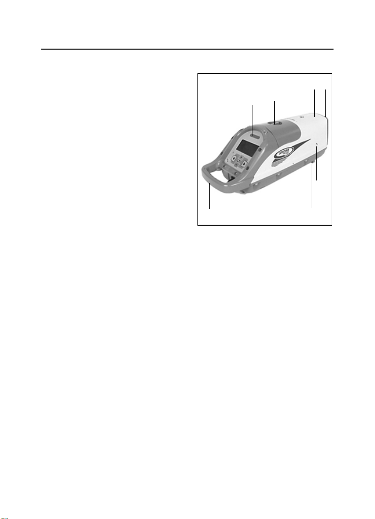
Laser 2.1
1 Beam-Exit Window – provides
a clear window for the laser beam
to exit the pipe laser.
2 Front and Rear Remote
Receiver Window – receives
signals from models RC501 and
RC502 Remote Control to perform
various keypad functions.
3 Line-Axis Pivot Marker and
LED – identifies the pivot point for
the pipe laser’s line system. The
LED lights for 15 minutes after
turning on the pipe laser or
pressing a control-panel button.
The LED also allows you to align a
transit over the top of the pipe
laser.
4 Alignment Markers –
correspond with the line system of
the pipe laser. Use them with the
Line Center feature to align the
laser with a distant control point.
1
2
4
3
20

2 Features and Functions
8 DG711 and DG511 Pipe Laser User Guide
5 Liquid Crystal Display (LCD)
– shows the power, grade, battery,
out-of-level, line position, and
status of the pipe laser.
6 Backlight/Lock Button –
activates the LCD’s backlight and
line-pivot LED. If you
simultaneously press this button
along with one of the line control
or grade buttons, it locks/unlocks
the control panel, so that the grade
and line system are not
unintentionally changed.
7 Power Button – turns the pipe
laser on/off. Press and hold the
button for about 2 seconds to turn
the unit off.
8 Left Line-Control Button –
moves the laser beam to the left
1
.
To center the line, this button has to
be pressed simultaneously with the
right line.
9 Right Line-Control Button –
moves the laser beam to the right
1
.
To center the line, this button has to
be pressed simultaneously with the
left line.
10 Negative Grade LED – lights
red to show that you have entered a
negative grade into the pipe laser.
11 Positive Grade LED – lights
green to show that you have
entered a positive grade into the
pipe laser.
12 Increase Button – increases the
grade.
1
To zero the grade and
change the grade in quick change
mode, press and hold this button
simultaneously with the decrease
button.
13 Decrease Button – decreases
the grade
1
. To zero the grade and
change the grade in quick change
mode, press and hold this button
simultaneously with the increase
button.
1.
Use this button in combination with others for further operations.
5
7
8 9
6
10
11
12 13
14
2
Features and Functions 2
DG711 and DG511 Pipe Laser User Guide 9
14 External Power Receptacle –
allows the pipe laser to be powered
by an optional external 6–16 VDC
power source.
15 5/8-11 Threaded Mount –
allows the pipe laser to be attached
to various setup accessories.
16 Grade-Axis Pivot Marker –
identifies the pivot point for the
pipe laser’s grade system.
17 Battery Pack – contains non-
replaceable Ni-MH batteries, or a
pack that can hold four replaceable
D-Cell alkaline batteries to power
the pipe laser (depending on
model).
18 Handle – allows you to carry
the pipe laser easily and provides a
safety-rope tie-off.
19 Armor Plated Housing – plated
with a special, hardened military
material for unsurpassed
ruggedness and reliability.
20 Protective Rubber Bumper –
protects the front end of the unit by
safeguarding the exit window.
16
18
17
15
19
2
20
2 Features and Functions
10 DG711 and DG511 Pipe Laser User Guide
Remote Controls 2.2
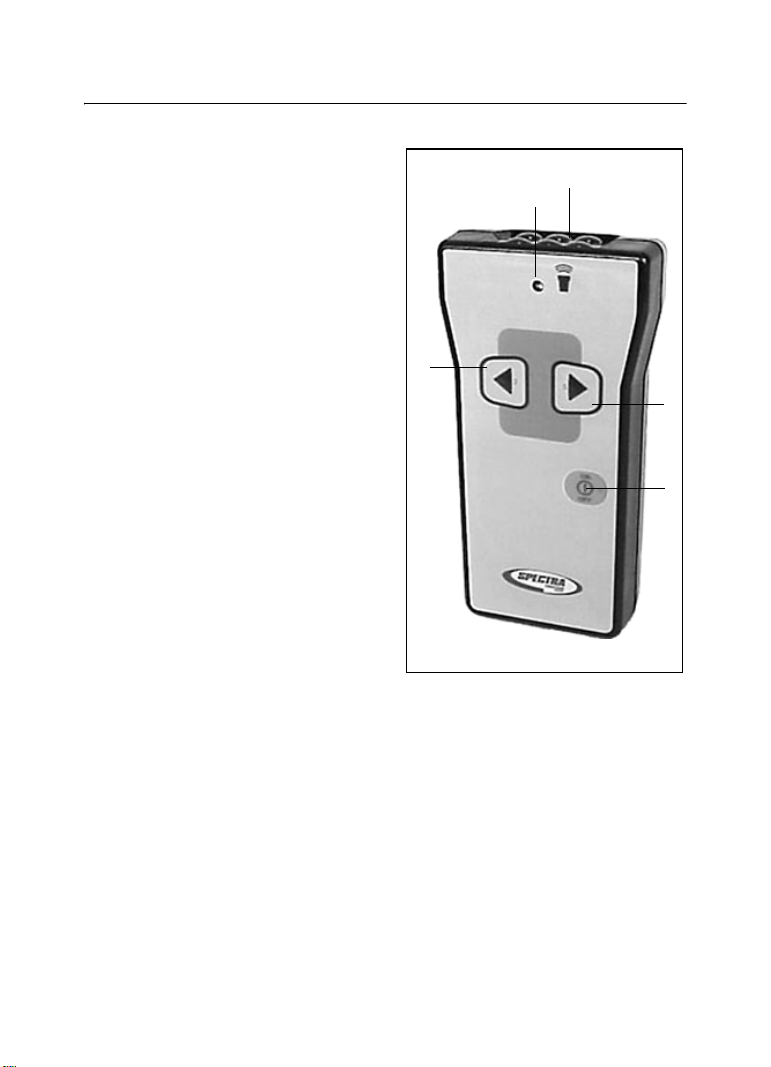
Model RC501, 3-Button
Remote Control 2.2.1
1 Power – turns the pipe laser
on/off. Press and hold the button
for about 2 seconds to turn the unit
off.
2 Left Line-Control Button –
allows you to move the laser beam
to the left.
3 Right Line-Control Button –
allows you to move the laser beam
to the right.
Note – Line Center – Press Left
Line-control and Right
Line-Control simultaneously to
center the line.
4 Status LED - flashes four times
per second when a line button is
pressed or once per second to
indicate that the internal battery is
low.
5 Emission Window – provides
an opening for the infrared signals
to exit from so that the remote
control and pipe laser can
communicate with each other.
2
3
4
1
5
Features and Functions 2
DG711 and DG511 Pipe Laser User Guide 11
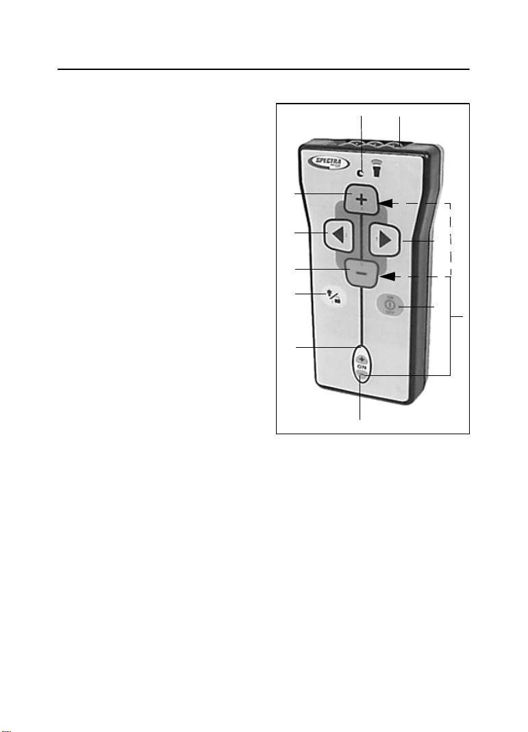
Model RC502, 7-Button
Remote Control
2.2.2
1 Power – turns the pipe laser
on/off. Press and hold the button
for about 2 seconds to turn the unit
off.
2 Grade-Enable LED – flashes
when the grade-enable function is
activated.
3 Grade-Enable Button –
activates/deactivates the increase
and decrease button. Deactivating
the grade-enable function prevents
the pipe laser grade value from
accidentally being changed.
4 Backlight/Lock Button –
activates the pipe-laser LCD’s
backlight. If this button is pressed
simultaneously with one of the line
control or grade buttons, it
locks/unlocks the control panel so
that the line and grade system do
not get accidentally changed.
5 Decrease Button – allows you
to decrease the grade.
6 Left Line-Control Button –
allows you to move the laser beam
to the left.
7 Increase Button – allows you to
increase the grade.
8 Status LED – flashes four times
per second when a control button is
pressed or once per second to
indicate that the internal battery is
low.
9 Right Line-Control Button –
allows you to move the laser beam
to the right.
10 Emission Window – provides
an opening for the infrared signals
to exit from so that the remote
1
4
5
6
9
8
7
3
2
10
11

2 Features and Functions
12 DG711 and DG511 Pipe Laser User Guide
control and pipe laser can
communicate with each other.
11 Grade Bump – If the Grade
Enable button and either Grade
button are pressed simultaneously,
the grade changes by one
increment. This function enables
small grade changes for matching
to existing grade.
DG711 and DG511 Pipe Laser User Guide 13
CHAPTER
3
Preparation
Before
Operation
3
Powering the
Laser 3.1
Ni-MH Batteries 3.1.1
Installing/Removing the
batteries
1 Turn the battery-pack knob
counterclockwise. Lift the battery
pack from the pipe laser.
2 Plug the battery-pack in place
and turn the battery knob
clockwise.
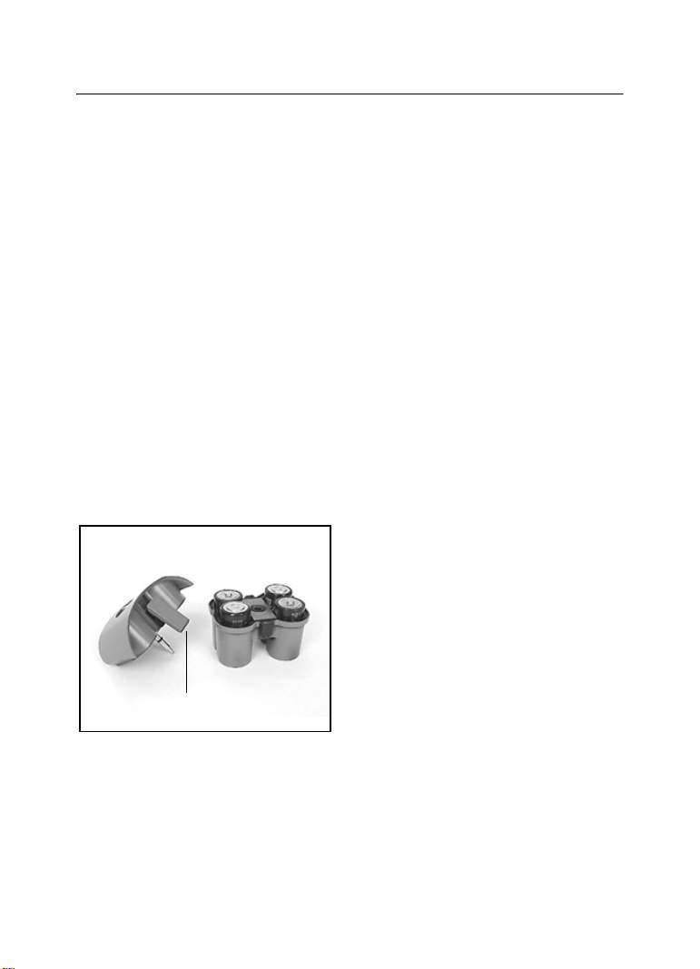
Optional Alkaline Battery
Pack
1 Turn the battery-pack knob
counterclockwise. Lift the battery
pack from the pipe laser.
2 Pull out on the top of the side
clips then push down on them to
release them from the side-clip
catches.
3 Preparation Before Operation
14 DG711 and DG511 Pipe Laser User Guide
3 Pull on the top housing to
separate it from the bottom
housing. Make sure to detach
latches from bottom housing.
4 Install/remove the batteries.
Note – When installing the
batteries, ensure that you take note
of the positive (+) and negative (-)
diagram inside of the housing.
Note – The pipe laser has reverse
polarity protection. If the batteries
are put in wrong, no damage
occurs to the pipe laser but it does
not work. Allow it one minute to
recover after the batteries have
been installed correctly.
5 Put the top housing back on the
bottom housing.
6 Position the side clips so that
they hold the top and bottom
housings together securely.
7 Put the battery pack in place
and turn the battery-pack knob
clockwise.
6

Preparation Before Operation 3
DG711 and DG511 Pipe Laser User Guide 15
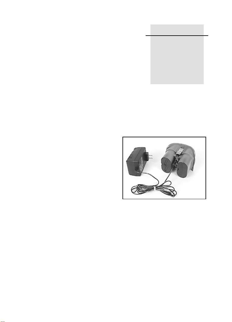
Smart Charger
The charger, to be used ONLY with the Ni-MH battery pack, starts
charging automatically as soon as a battery pack is installed and the charger
is plugged in. The LEDs on the charger indicate the condition shown in
Table 3.1.
Discharge Button: Pressing the
button for approximately 2 seconds
the charger automatically
discharges the battery and switches
over to charging. The process of
discharging the battery before
charging should be performed
every three months to help prevent
loss of battery capacity due to
frequent partly discharging.
Table 3.1 LED condition
LED condition Description
Red LED On Batteries are charging
Green LED on Batteries are fully charged, and the charger has
switched to trickle charge
Flashing red LED Battery-contact detection (test phase)
Battery-pack reversed
Battery pack broken, open or unsuitable cells
The batteries are discharging after pressing the
discharge button
Green LED
Red LED
Discharge
Button

3 Preparation Before Operation
16 DG711 and DG511 Pipe Laser User Guide
Charging Time:
Table 3.2 shows the approximate charging time for 4 to10 batteries with a
7500 mAh capacity.
Recharging the batteries
Note – A sealed Ni-MH battery
pack is offered in most standard
models (P23/P23B).
1 Turn the battery-pack knob
counterclockwise. Lift the battery
pack from the pipe laser.
2 Plug the battery recharger's
single-socket plug into the battery
pack's recharging receptacle.
3 Plug the battery recharger into
an appropriate outlet.
Note – The charger takes 10 hours
to charge the batteries to full
capacity.
Note – To extend battery life, the
charger discharge function should
be performed after every three
months of charging.
C
Warning – Do not charge
the batteries above 45°C
(113°F).
External Power Cable
P21 3.1.2
In case the internal batteries
become discharged and you do not
have spare batteries available, you
can also power the pipe laser using
an optional external power cable.
This can be achieved by using a
DC regulated automotive or
motorcycle battery with the
supplied optional external power
cable on some models. The internal
batteries will not recharge while
you’re using the external power
cable.
Table 3.2 Charging time
# of Cells Cell Capacity Approximate Charging Time
4 7500 mAh 10 Hours with smart charger
4 7500 mAh 14 Hours with 12V Cigarette Lighter
Charger Model P22

Preparation Before Operation 3
DG711 and DG511 Pipe Laser User Guide 17
While using the optional external
power cable and 12-V DC battery
to power the pipe laser, you can
remove the internal batteries and
the pipe laser will continue to
operate. The battery pack however
has to be in place in order to cover
the contacts.
Connecting/Disconnecting
the external power cable
C
Warning – To a v o i d
damaging the pipe laser
and to prevent the
possibility of creating a
spark at the battery, make
sure the pipe laser is off
before connecting/
disconnecting the external
power cable to/from the
pipe laser.
C
Warning – Do not
connect the pipe laser to a
power generator where
over-voltage can occur. Do
not start the vehicle while
the pipe laser is
connected to the external
battery.
C
Warning – An electrical
shock risk may occur if
you connecting/
disconnecting the power
plug or power cable from
the pipe laser with wet
hands. Make sure your
hands are dry when
performing this task.
1 Turn the external-power-
receptacle cap counterclockwise
enough to remove it from the
external power receptacle.
Removing the cap exposes the
receptacle.
2 Connect the alligator clips to a
12-V dc automotive or motorcycle
battery noting the correct polarity
(red = positive, black = negative).
3 Insert the plug into the
receptacle on the laser.
4 To disconnect the external
power cable from the pipe laser,
remove the plug from the pipe laser
first and then remove the alligator
clips from the battery.

3 Preparation Before Operation
18 DG711 and DG511 Pipe Laser User Guide
Optional Features 3.2
The DG511/711 has various
optional features that your
salesman or service personnel may
configure according to your
individual needs.
For more information, contact your
Trimble dealer.

DG711 and DG511 Pipe Laser User Guide 19
CHAPTER
4
Getting Started 4
Press the On/Off button to turn on the Laser. Press and hold the button for
about 2 seconds to turn the unit off.
If your laser displays a language other than what you need, consult your
salesman or service center for re-configuration.
The following languages are available:
• English
• Dutch / Netherlands
• French / Francais
• German / Deutsch
• Italian / Italiano
• Japanese
• Portuguese
• Spanish / Espanol
• Swedish /Svensk
• Finnish / Suomi

4 Getting Started
20 DG711 and DG511 Pipe Laser User Guide
Table 4.1 contains a list of the DG511/711 feature options.
Table 4.1 DG511/711 feature options
DG711 DG511 Main
Features
Options
Description
99
Service
Check
Selects user calibration interval reminder
99
Grade
Display
Floating Displays three (3) significant
digits on grades less than
10%, 2 digits on grades
greater than 10%
Example: 1.234% 12.34%.
Fixed Displays two (2) digit grade.
1.23% or 12.34%
Per Mille Displays grade in millimeters
per meter.
12.34‰
Rise/Run
Slope
Displays grade as Rise / Run =
1.234 rise over 100 ft run
99
Grade
Entry
Step and
Go
“Step” through grade with
single grade button actuation
or “Go” through grade changes
at an increasing rate.
Digit
Select –
Enables an individual grade
“Digit” to be “Selected” and
changed until the required
grade is entered.

Getting Started 4
DG711 and DG511 Pipe Laser User Guide 21
99
Quick
Grade
Mode
(Grade
Zero)
Enables instant resetting of the grade to
“Zero” by holding both grade buttons
simultaneously. Continuous holding of
both grade buttons puts the unit in Quick
Grade mode.
99
Grade
Lock
Prevents any changes to the grade
system.
9
Line
Set/Check
Moves the laser vertically to its maximum
limit, which aids in setting line.
99
Language Sets user’s local language. For more
information, see page 19.
9
Line Alert Flashes the laser beam two times per
second if the unit is disturbed after a 5
minute set up period.
99
Line
Center
Automatically centers Line system when
line is moved to a reference point.
9
Line Limit Enables complete movement of the laser
to the left or right line limit.
99
Line Lock Locks out line system controls once the
required line setting is reached.
99
Low Batt
Warning
Flashes laser two times a second
indicating the low battery condition.
Table 4.1 DG511/711 feature options (Continued)
DG711 DG511 Main
Features
Options
Description

4 Getting Started
22 DG711 and DG511 Pipe Laser User Guide
99
Steep
Grade
Disables the self-leveling system but
keeps the laser beam turned on for
applications where you need to manually
point the laser beam at steeper grades
than allowed by the self-leveling system.
99
Name Displays owner’s name as entered by local
dealer.
9
Power
Saver
(Standby)
Turns the laser beam off when not being
used to conserve battery life, but keeps all
other systems operational.
99
Roll Vial
Warn
Flashes the laser beam once per second
and the LCD displays that the unit is
beyond its roll leveling range.
9
Security When active, the Laser prompts you for a
four-digit password before it will operate.
An incorrect password turns the unit off.
99
Status When activated, the LCD indicates which
functions have been activated and
displays the status of those activated
functions.
99
Auto Shut
Down
The unit automatically turns off after 15
minutes of an out-of-level condition.
99
Calibration
Option
Changes factory default calibration
settings.
Table 4.1 DG511/711 feature options (Continued)
DG711 DG511 Main
Features
Options
Description
Loading...