

Page 1
XS-3000 Quick Reference Guide
8
5
6
1
13
14
15
16
AUTO
O
zZz
I
OK
3
I
I
I
SPD/
MOD
CLR
2
3
4
12
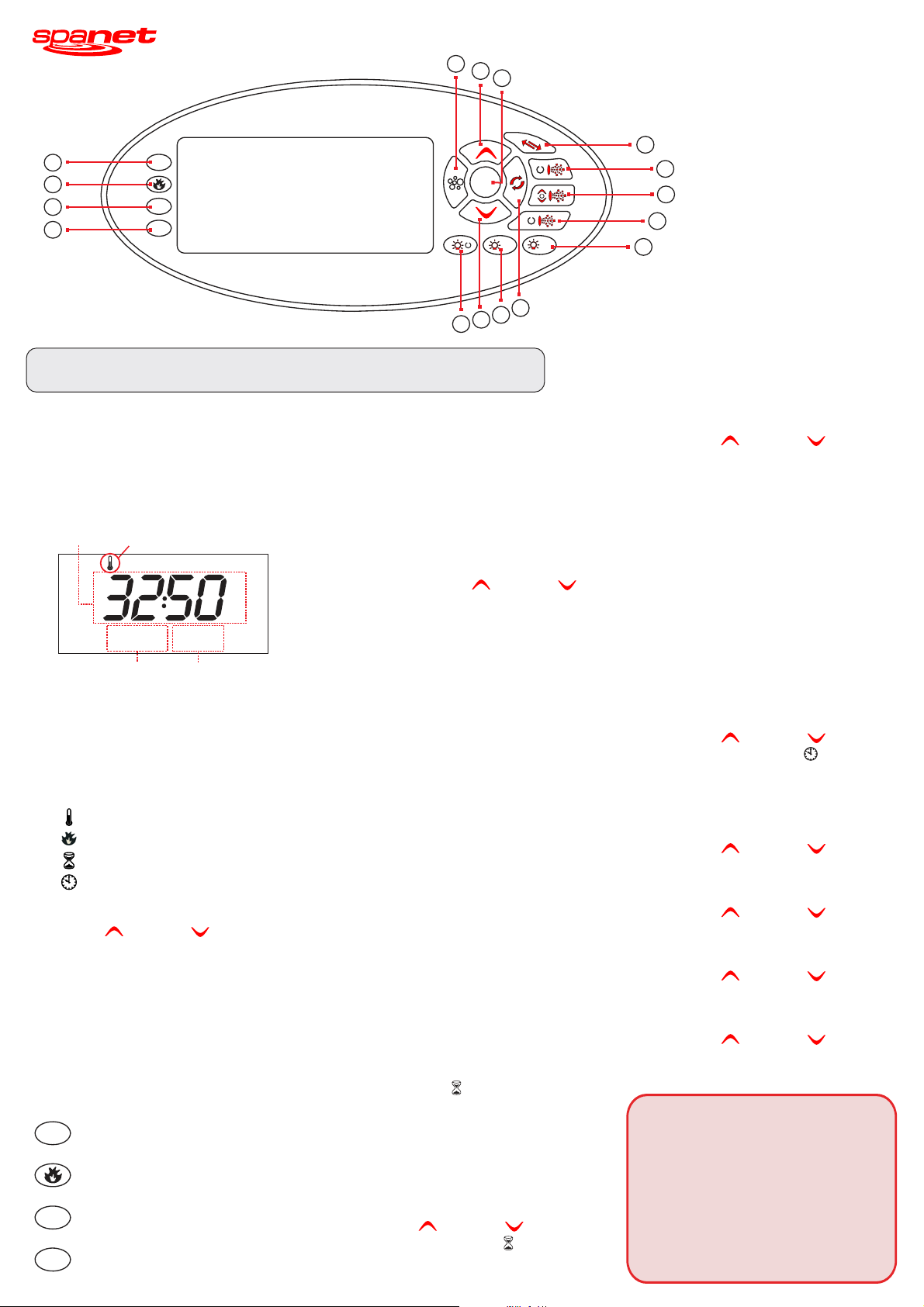
Buttons:
1.
Invert Display 180
2.
Pump A
3.
Pump B
4.
Pump C
5.
UP
6.
OK
7.
DOWN
8.
Air Blower
9.
One-Touch Sanitise
10.
Light (On /Off)
11.
Light Mode
12.
Light (Speed / Colour)
o
7
10
NOTE: www.spanet.com.au/XS_support.htmlFor complete user manual please log on to and
download PDF version from the User Manual link.
DISPLAY MODES
The XS-3000 topside panel features a large LCD
screen which displays three items: (1) Actual Water
Temperature (2) Set Temperature Point (3) Time &
Day. By default the actual water temperature is
displayed in the large digits (refer below).
Actual
Water Temp
W.TMP Display Mode Icon
ADJUST SET TEMPERATURE POINT
The SpaNET intelligent software constantly monitors
the spa water, automatically controlling the heater
and circulation pump to ensure the desired set water
temperature is maintained. The user can adjust the
set temperature point from5C-41C insteps of
oo
0.2 C increments(Default: 38 C).
oo
To adjust the set temperature point:
BRT
SPD
MODE
°F
OFF
°C
ON
PM
AM
SA SU TU WE TH FRMO
AM
PM
10:30
Time & Day Set Temp Point
38.0
SET TEMP
There are four possible items that can be displayed
in the large digits: (1) Actual Water Temperature
[W.TMP]*; (2) Set Temperature [S.TMP];
(3) Countdown Timer [TIMR]; (4) Time Clock [TIME].
Each display mode has a unique icon shown at the
top of the screen to indicate the current item being
viewed (refer below).
W.TMP Water Temperature*
S.TMP Set Temperature
TIMR Countdown Timer
TIME Clock
* Default Display
Press the ( ) or ( ) button to scroll
UP DOWN
through these different display modes. As you scroll
°C
°F
MODE
SPD
BRT
SET TEMP
°C
°F
1) the
Press and hold
button. The set temperature point will begin
adjusting up or down in 0.2 C increments.
()or ()UP DOWN
o
2) Once the desired set temperature is displayed
press the ( ) button to confirm selection.
Notes: 1) If the optional in-pool temperature sensor is fitted
the heater works off a 0.5 C hysteresis (thermostat). The
OK
OK
o
heater will raise the water to the set temperature point but
thereafter will not be re-activated until the water
temperature falls by at least 0.5 C. Therefore if the spa
o
user selects a set temperature point of 38 C the actual
water temperature will be anywhere between 37.5C-38C
depending on when the user checks the temperature.
2) If the standard in-heater temperature sensor is used (i.e.
no optional in-pool temperature sensor fitted) the heater
works offa2Chysteresis (thermostat). The heater will
o
raise the water to the set temperature point but thereafter
will not be re-activated until the water temperature falls by
o
at least 2 C.Therefore if the spa user selects a set
temperature point of 38 C the actual water temperature will
be anywhere between 36C-38Cdepending on when the
o
oo
user checks the temperature.
through each item a brief title screen will be shown
followed by the actual display mode (note change in
COUNTDOWN TIMER
icon).
Note: There is a ten (10) second timeout on viewing non
default display modes. If no button press is sensed after 10
seconds the screen will return to the default display.
The XS-3000 features an integrated countdown
timer that enables the user to set an audible alarm to
sound after a user determined period (5-60 minutes).
The timer will count down the selected period and
show minutes and seconds remaining on the LCD as
LED INDICATOR LIGHTS
The AUTO LED indicator turns ON when
AUTO
the filtration pump is in automatic mode.
The Heater LED indicator turns ON when
the heater element is active.
The Ozone LED indicator turns ON when
3
O
the ozonator / UV sanitiser is active.
The Sleep Cycle LED indicator turns ON when
zZz
in a designated sleep cycle (if programmed).
it does. The timer icon ( ) will be displayed in the
top right of the LCD screen whilst the timer is
running. Once the countdown time has elapsed the
topside panel will beep for one minute or until a
button is pressed.
time-out periods are NOT adjusted by the minute timer.
NOTE: The pump(s), blower and light
To start the countdown timer:
1) Press the ( ) or ( ) button to
toggle the screen to the ( ) display mode.
2) Press ( ) to select desired time period.
UP DOWN
OK
OK
TIMR
9
11
3) Press the ( ) or ( ) button to
Indicator Lights
13.
Auto Mode LED
14.
Element On LED
15.
Ozone/UV On LED
16.
Sleep Cycle LED
UP DOWN
adjust the timer in minute increments until the
desired time period is selected.
4) Press ( ) to confirm and begin countdown
OK .
OK
CLOCK
For convenient user reference and to assist in
filtration & sleep time functions, your spa controller
includes a built-in real time clock. The user can
choose to display the time in either 12 or 24 hour
format. For ease of reference the current time and
day is displayed at the bottom left of the LCD
screen.
To set the clock:
o
oo
1) Press the ( ) or ( ) button to
toggle the screen to the ( ) display
mode.
2) Press the ( ) button to enter set time
UP DOWN
TIME
OK
OK
adjustment.
3) Press the ( ) or ( ) button to
UP DOWN
select the time format (12 or 24 HR). Press
the ( ) button to confirm selection.
OK
OK
4) Press the ( ) or ( ) button to
UP DOWN
modify the weekday (Mon - Sun). Press the
( ) button to confirm selection.
OK
OK
5) Press the ( ) or ( ) button to
modify the hour. Press the ( ) button to
UP DOWN
OK
OK
confirm selection.
6) Press the ( ) or ( ) button to
modify the minutes. Press the ( ) button
UP DOWN
OK
OK
to confirm selection.
Safety Notes:
The appliance must be connected to a suitably rated and
weather protected power supply. The supply line should be a
dedicated power circuit and means for disconnection must
be incorporated in the fixed wiring in accordance with your
local wiring regulations. Means for disconnection from the
supply mains should have a contact separation in all poles
that provide full disconnection under overvoltage category III
conditions.
The appliance must be supplied through a
residual current device (RCD) having a rated residual
operating current not exceeding 30mA.
not intended for use by young children or infirm persons
without supervision.
This appliance is
Page 2
PUMP BUTTONS
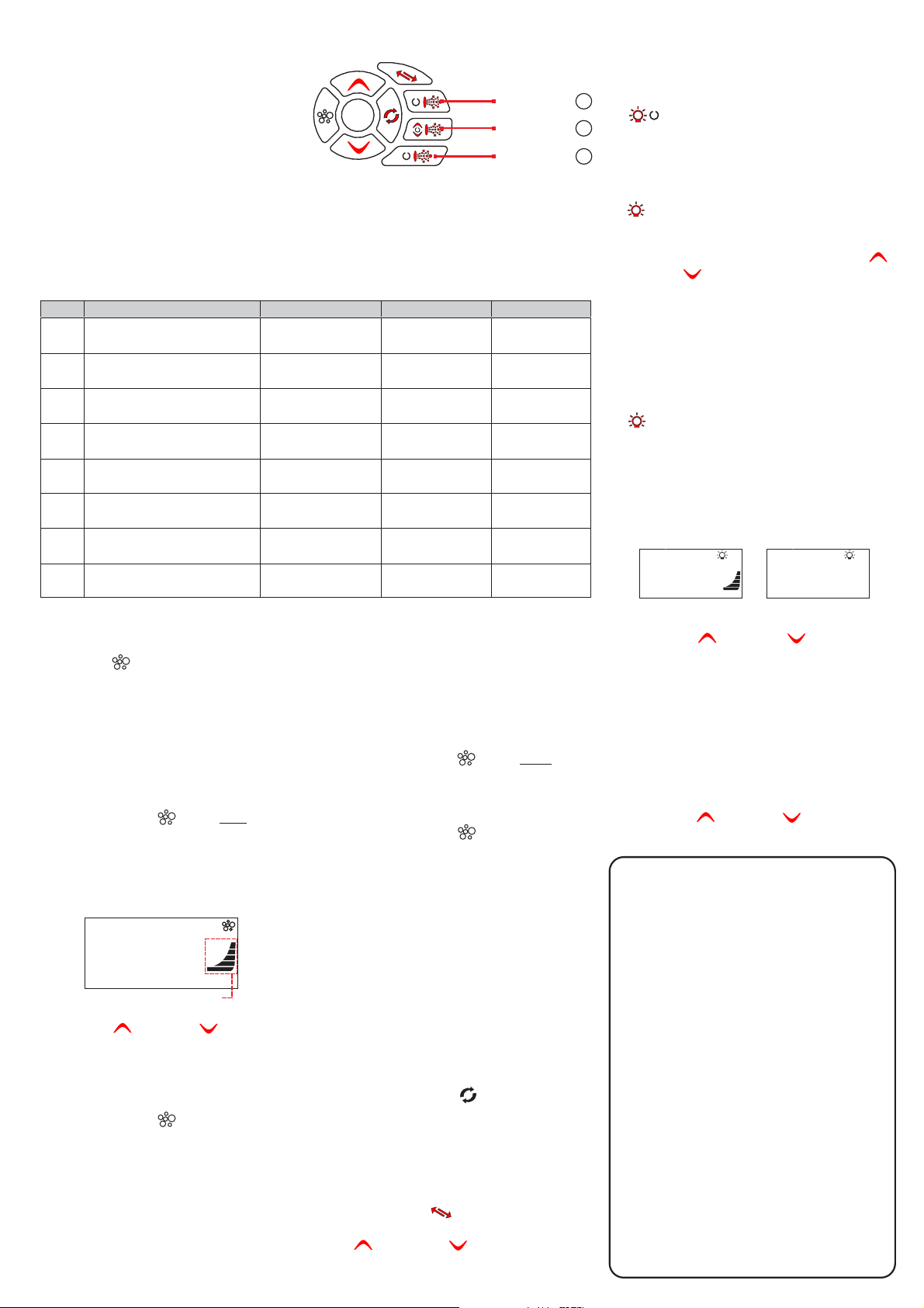
There are three pump buttons on the right hand side
of the touch pad: Pump A, Pump B and Pump C. The
functions of the three buttons change depending on
pump / controller configuration. The intention is to
make best possible use of these buttons for all
possible configurations. For every press of a pump
button, the display will temporarily show the selected
pump state: then
ON / OFF / LOW / HIGH / AUTO
OK
I
I
I
Pump Button
Pump Button
Pump Button
A
B
C
revert to the default display mode. Possible pump configurations & button sequences are referenced in the table
below (Please tick your spa configuration for ease of future reference).
LIGHT BUTTONS
Three light buttons are used to control the many
features of the multi colour LED spa light.
I
( ) LIGHT ON / OFF BUTTON
Press to toggle light and . The button is
ON OFF
backlit green to indicate when the light has been
turned ON.
MOD
( ) LIGHT MODE
Notes: 1) If left ON pumps will automatically time-out and turn off 30 minutes after the last sensed button press.
2) In some configurations if heater is ON activating multiple pumps OR turning the blower ON may cause the spa control to
load shed and turn the heater OFF. This is to keep the system within its maximum power load.
Spa Configuration Button A Button B Button C
No small circ pump
P1 & P2 = 1 speed
No small circ pump
P1, P2 & P3 = 1 speed
No small circ pump
P1 = 2 speed
No small circ pump
P1 = 2 speed, P2 = 1 speed
Small circ pump fitted
P1 & P2 = 1 speed
Small circ pump fitted
P1, P2 & P3 = 1 speed
Small circ pump fitted
P1 = 2 speed
Small circ pump fitted
P1 = 2 speed, P2 = 1 speed
AIR BLOWER BUTTON
The BLOWER ( ) button is used to control the air
blower and allow adjustment of the blower speed.
The last used speed is saved and will be restored the
Jet pump 1 :
On/Off/Auto
Jet pump 1 :
On/Off/Auto
Jet pump 1 :
Low / Off / Auto
Jet pump 1 :
Low / Off / Auto
Small circ pump :
On/Off/Auto
Jet pump 1 :
On / Off
Small circ pump :
On/Off/Auto
Small circ pump :
On/Off/Auto
RAMPING BLOWER MODE
The spa controller features a ramping blower mode,
were the blower speed gradually fluctuates between
high and low in a ramping manner.
Jet pump 2:
On / Off
Jet pump 2:
On / Off
Jet pump 1:
High / Low
Jet pump 1:
High / Low
Jet pump 1:
On / Off
Jet pump 2:
On / Off
Jet pump 1:
Low / Off
Jet pump 1:
Low / High / Off
No Function
Jet pump 3:
On / Off
No Function
Jet pump 2:
On / Off
Jet pump 2:
On / Off
Jet pump 3:
On / Off
Jet pump 1:
High / Low
Jet pump 2:
On / Off
next time the blower is turned on, for future ON/OFF
Note: that when the blower is first turned on it will run
use.
To turn the blower on in ramping mode:
at maximum speed for approx three seconds before
changing to your preset speed; this is normal.
To turn the blower on/off:
1) Press the ( ) button to start
the blower in ramping mode.
ON and the screen will display [RAMP] to indicate
BLOWER
twice
The blower will turn
ramping mode.
1) Press the ( ) button to turn
the blower ON in variable speed mode.
BLOWER
once
2) Press the ( ) button again to turn
BLOWER
the blower OFF.
2) The blower will turn ON (at the last used speed)
and the screen will display the blower speed
[B.SPD] adjustment screen (refer below).
ONE-TOUCH SANITISE BUTTON
A sanitise cycle runs the filtration pump and ozone /
BRT
SPD
MODE
°F
OFF
°C
ON
6.S PD
SPD
uv (if fitted) to filter the spa water to restore and
refresh water quality after use. In addition, at the
start and end of the cycle, the controller will
sequentially run any additional pumps and the
Bargraph indicates blower speed
3) Use the ( ) or ( ) buttons to
UP DOWN
adjust the blower speed.
Note: the bar graph will
change indicating current blower speed.
4) Press the ( ) button to confirm selection.
5) Press the ( ) button again to turn
OK
OK
BLOWER
the blower OFF.
Note: The B.SPD adjustment screen is displayed for 10
seconds when the blower is first turned ON. If no
adjustment is made the blower will run at the last used
speed setting, and the screen will time-out and revert to the
default display mode. If you wish to adjust the blower speed
once the blower has been running for a period of time, the
blower must be turned OFF and back ON again to restore
the B.SPD adjustment screen.
blower (if fitted) for one minute each to purge the
plumbing and clear any unfiltered water trapped in
those lines.
To activate a 20 minute water clean-up cycle:
1) Press the ( ) button once after spa
SANITISE
use to activate the water clean [W.CLN] cycle.
Note:
If cycle running, cycle can be cancelled by
pressing the button again.
SANITISE
INVERT BUTTON
Press the ( ) button to flip the screen
180 for ease of viewing when spa in use. The
UP DOWN
INVERT
o
( ) and ( ) button functions also
change (invert) to match the new display.
Press to activate the light mode menu. The current
light mode in use will be displayed. Use the ( )
DOWN
or ( ) button to step through the five
UP
colour modes:
(1) White [WHTE]
(2) User Colour [U.CLR]
(3) Fade Effect [FADE]
(4) Step Effect [STEP]
(5) Party Effect [PRTY]
SPD/
( ) LIGHT SPEED / COLOUR
CLR
Press to activate the light speed [L.SPD] or user
colour [CL:xx] adjustment screens. If FADE / STEP or
PARTY effect modes are selected the current light
speed [L.SPD] will be displayed. If the user colour
[U.CLR] light mode is selected the current colour
number will be displayed (refer below).
°C
OFF
ON
L.SPD
SATSUN MON TUE WED THU FRI
Light speed screen User colour screen
Press the ( ) or ( ) button to adjust
UP DOWN
AM
OFF
PM
°F
ON
MODE
SPD
BRT
CL:01
SATSUN MON TUE WED THU FRI
°C
AM
PM
°F
MODE
SPD
BRT
the light effect transition speed OR select from 30
colour choices. Press ( ) to confirm selection
OK
OK
or wait for the 10 second idle menu timeout where the
screen steps to the light brightness [L.BRT] screen.
Note: If White [WHTE] colour mode is selected the Light
Speed/Colour button has NO function.
[L.BRT] LIGHT BRIGHTNESS
When the [L.BRT] adjustment screen is displayed
press the ( ) or ( ) button to adjust
UP DOWN
the light brightness.
ERROR CODES / DIAGNOSTICS
Note: most error conditions require mains power to be turned
ON
and back before the error is cleared.
ER2 - HEATER PLUG:
"Heater" sensor lead is plugged firmly into the spa control.
ER3 - WATER PRIME:
Pump A button to retry water prime. Check spa water level, clean
and soak filters, bleed potential air locks from pipework.
ER4 - THERMAL TRIP:
heating has activated thermal cut-out device on heater. Turn mains
power OFF and wait 20~30 minutes for heater to cool and thermal
cut-out to reset.
all shut-off valves are open, bleed potential air locks from pipework.
ER5 - POOL TOO HOT:
temperature reading in excess of 45 C.
spa to cool. Check daily filtration time & reduce setting if required.
ER6 - HEATER SENSOR:
and heater has been lost.
reconnect "Heater" sensor lead from spa control.
ER7 - IN POOL SENSOR:
faulted.
Contact your local dealer. Disconnect "In Pool Sensor" lead
from spa control to continue spa operation.
ER8 - CTRL FAULT:
Reset mains power. Contact your local dealer if problem persists.
Heater sensor cable fault.
Heater tube failed to fill with water.
Low or NO water flow over element whilst
Check spa water level, clean & soak filters, check
Temperature sensor has reported a
o
Remove spa cover & allow
Communication between spa control
Turn mains power OFF and unplug and
In Pool Temperature Sensor has
An internal controller fault has been detected.
OFF
Check the
Press
 Loading...