


We have provided important safety messages in this manual about your heat pump.
Always read and follow all safety messages.
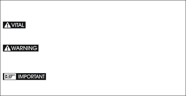
This is the safety alert symbol.
This symbol alerts you to hazards that can cause injury or harm to you and others.
This is a very important label.
This symbol alerts you of things that MUST be strictly adhered to in order to ensure that your warranty will not be voided.
These are things that must be respected in order to protect the health of spa users and to ensure that your warranty will not be voided.
1

Safety Warnings
 Electrical power must be switched off before starting any work on heat pump. DONOT attempttomodifytheinternalconfigurationoftheheatpump.Read entire installation manual before use.
The installation, commissioning and maintenance of these heat pumps should be performed by qualified personnel having a good knowledge of standards and local regulations, as well as experience with this type of equipment.
The appliance is intended to connect to fixed wiring.
The SV heat pump is preinstalled with an AMP power cable for direct power connection to the SV spa control. If the installer decides to connect power to the heat pump from a source other than the SV spa control, all electrical connections must be performed by a licensed electrician and must confirm to all national, state and local electrical codes in effect at the time of installation.
It is the responsibility of the installer to ensure circuit breaker protection, considering the spa control and heat pump capacity. The SV spa control and SV heat pump should also be supplied through a residual current device (RCD) having a rated residual operating current not exceeding 30mA.
The SV spa control must be connected to a suitable rated and weather protected power supply. The supply line should be a dedicated power circuit and means for disconnection must be incorporated in the fixed wiring in accordance with your local wiring regulations. Means for disconnection from the supply mains should have a contact separation in all poles that provide full disconnection under over voltage Category III conditions. If the SV heat pump does not source power directly from the SV spa control these precautions should also be followed for the heat pump power supply.
The SV heat pump must be earthed to avoid any risks caused by insulation defects. The heat pump will be earthed via the pre installed AMP power cable which connects to the SV spa control. If a different power source is used, ensure the heat pump is connected to earth.
Earthed appliances must be permanently connected to fixed wiring (European models).
The data cable should be installed and run through UV resistant, corrugated conduit suitable for use in outdoor locations.
The appliance contains no serviceable parts. Do not attempt service of this appliance. Contact your dealer or authorized service agent for assistance.
Turn the mains power OFF before touching or modifying any cable connection.
Low voltage or improper wiring may cause damage to this appliance. Read and follow all wiring instructions when connecting to power supply.
If the supply cord is damaged, it must be replaced by the manufacturer, its service agent or similarly qualified persons in order to avoid a hazard.
It is the installer's responsibility to ensure the floor or mounting base can support the expected load of the heat pump and an adequate drainage system must be provided in case of overflowing or leaking water.
2
This appliance must not be installed in proximity to highly flammable materials.
Water temperature in excess of 38oC may cause hyperthermia (heat stress).
This appliance is not intended for use by persons (including children) with reduced physical, sensory or mental capabilities, or lack of experience and knowledge, unless they have been given supervision or instruction concerning use of the appliance by a person responsible for their safety (IEC 60335 1)
Children should be supervised to ensure that they do not play with the appliance.
This appliance can be used by children aged from 8 years and above and persons with reduced physical, sensory or mental capabilities or lack of experience and knowledge if they have been given supervision or instruction concerning use of the appliance in a safe way and understand the hazards involved.
Children shall not play with the appliance. Cleaning and user maintenance shall not be made by children without supervision (EN 60335 1)
Do not spray or paint insecticidal material on the surface of the heat pump
Do not block the evaporator by paper or any other foreign bodies to keep the unit well ventilated.
You can clean the evaporator by washing with detergent and water at low pressure and then rinsing with clean water.
Do not touch the air outlet grill when fan motor is running.
The heat pump should be plumbed after the spa filters and NOT before, to prevent foreign objects or debris from entering heat pump.
Spanet SV series heat pumps can only be used with Spanet SV series controllers.
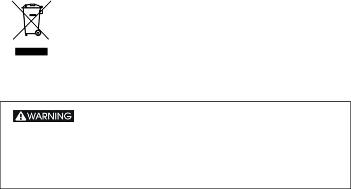
Correct Disposal of this Product
This symbol indicates the product should not be mixed or disposed with general household wastes throughout the EU. Disposing of this product correctly will help save valuable resources and prevent any potential negative effects on human health and the environment, which could otherwise arise from inappropriate waste handling. For proper treatment, recovery and recycling, please take this product to designated collection points where it will be accepted free of charge. Alternatively, you may be able to return your products to your
local retailer upon purchase of an equivalent new product. Please contact your local authority for further details of your nearest designated collection point. Penalties may be applicable for incorrect disposal.
When ambient temperatures are close to or under freezing point, water circulation to the heat pump should never be stopped for more than 4 hours without completely draining the heat exchange. In areas where freezing conditions are prevalent and sustained, in advance of any freeze event, all
water MUST be removed from the entire heat pump water circuit. Please refer to the “Winterising” section of this manual. FREEZE DAMAGE NOT COVERED UNDER PRODUCT WARRANTY
3
Table of Contents
Safety Warnings........................................................................................................................... |
2 |
|
Introduction................................................................................................................................. |
5 |
|
Specifications............................................................................................................................... |
6 |
|
1. |
Outlines & Dimensions...................................................................................................... |
7 |
2. |
External Appearance.......................................................................................................... |
8 |
3. |
Internal appearance .......................................................................................................... |
9 |
4. |
Installation Instructions................................................................................................... |
10 |
5. |
SV Controller Setup.......................................................................................................... |
17 |
6. |
Safety / Protection Systems............................................................................................. |
19 |
7. |
Winterizing heat pump.................................................................................................... |
20 |
8. |
Temperature Sensor Calibration..................................................................................... |
23 |
9. |
Maintenance.................................................................................................................... |
25 |
10. |
Troubleshooting............................................................................................................... |
26 |
11. |
Heat Pump Error Codes................................................................................................... |
27 |
12. |
Wiring Diagram.............................................................................................................. |
30 |
Contact Us.................................................................................................................................. |
31 |
|
4

Introduction
Thank you for choosing the SpaNET SV Series heat pump. Air sourced heat pumps are currently the most efficient and cost effective method of heating and maintaining the heat of your spa pool water. The SpaNET SV Series heat pump technology heats your spa water using around 75% less energy than a conventional electric heater and 50% less energy than natural gas resulting in an eco friendly and highly cost efficient appliance. It also allows for maximum heating input and reduced heating times on low amperage power supplies. The SV Series heat pumps have been engineered for maximum heating efficiency however as a by product of refrigeration technology they can offer cooling of the spa water as well.
SpaNET SV Series heat pumps have been specifically designed to integrate to SpaNET SV Series spa controllers. SpaNET heat pumps will NOT operate on any other spa control system. They do not have a separate keypad for adjusting settings; rather they feature a dedicated interface to the SV Series spa controller allowing all temperature settings and mode adjustments to be conveniently controlled via the spa side keypad.
They offer a truly integrated heat pump solution for a spa pool that can not only provide automatic heating of the spa water, but automatic cooling of the spa water as well. Simply set your desired water temperature on the spa side keypad and the SV heat pump will automatically heat or cool the water (when required) to maintain your desired water temperature level (from 10°C to 41°C). They offer outstanding efficiency, low noise and high build quality. They are easy to use and maintain and when installed correctly will provide years of trouble free service.
Please read this instruction manual carefully before use and follow all installation guidelines in order to prevent damage to the device and ensure long term reliability. Specifications are subject to change without notice for further improvement.
1)In extreme cold weather (ongoing temperatures below 0°C), when the heat pump is no longer needed, it is important to isolate water flow to the heat pump and drain all water from the inside of the heat pump. Please refer to the “Winterising” section of this manual.
2)The heat pump should NOT be installed in an airtight location or confined space, such as a basement or garage. The heat pump requires good air ventilation. It will discharge cold air when heating and hot air when cooling, and efficiency depends on the ability to draw normal ambient temperature air and discharge the cold or hot air well away from the unit. It is recommended to install the heat pump away from any other home appliances, to avoid the chance of electromagnetic interference. Please refer to the “Air Space Requirements” section of this manual.
3)In very hot weather (ongoing temperatures exceeding 36°C) and where the spa water temperature exceeds 32°C and the heat pump is set to AUTO mode and engages to cool the water, it is possible that the critical temperature of the R410a refrigerant is exceeded once the heat pump has been operating for a period of time and an error condition may occur to protect the compressor. If this occurs wait until the ambient temperature falls before attempting to cool again or cool the spa water in advance of any forecast hot weather event. Heat pumps installed in highly sun exposed areas or locations with restricted air ventilation will be more prone to this situation.
5

Specifications
|
Description |
|
SN HP 55P |
|
SN HP 90P |
|
|
SN HP 120P |
||
|
Power supply |
|
220 240V~/1PH/50Hz |
220 240V~/1PH/50Hz |
|
220 240V~/1PH/50Hz |
||||
|
|
|
|
|
|
|
|
|
|
|
|
HEATING TEST CONDITION: |
|
Air Temp = 25’C |
Air Temp = 25’C |
|
Air Temp = 25’C |
||||
|
|
Water Temp = 27’C |
|
Water Temp = 27’C |
|
|
Water Temp = 27’C |
|||
|
|
|
|
|
|
|||||
|
Heating capacity |
|
5.6 kW |
|
8.6 kW |
|
|
12.0 kW |
||
|
Heating input |
|
1.1 kW |
|
|
1.65 kW |
|
|
2.2 kW |
|
|
COP |
5.1 |
|
5.21 |
5.45 |
|
||||
|
Rated heating current |
|
5.3A |
|
|
7.8A |
|
|
10.8A |
|
|
Cooling capacity |
|
3.8 kW |
5.3 kW |
|
|
8.4 kW |
|||
|
|
|
|
|
|
|
|
|
||
|
Cooling input |
|
1.3 kW |
|
|
2.0 kW |
|
|
2.4 kW |
|
|
Rated cooling current |
|
5.8A |
|
8.5A |
|
|
11.5A |
||
|
EER |
|
2.92 |
|
|
2.65 |
|
|
3.5 |
|
|
Refrigerant |
|
R410A, 600g |
|
R410A, 950g |
|
|
R410a, 1400g |
||
|
Air Flow (m3/H) |
|
1600 |
|
|
1700 |
|
|
2600 |
|
|
Sound pressure level |
|
<49 dB(A) |
|
<49 dB(A) |
|
|
<51 dB(A) |
||
|
|
|
|
|
|
|
||||
|
Protection class |
|
1 |
|
|
1 |
|
|
1 |
|
|
Waterproof class |
|
IPx5 |
|
IPx5 |
|
|
IPx5 |
||
|
Net weight |
|
45Kg |
|
|
53Kg |
|
|
62Kg |
|
|
Fan speed |
|
850 RPM |
|
850RPM |
|
|
1000RPM |
||
|
Water temperature range |
|
10 to 41’C |
|
|
10 to 41’C |
|
|
10 to 41’C |
|
|
Operating temperature range |
|
0’C to 40’C |
|
0’C to 40’C |
|
|
0’C to 40’C |
||
|
|
|
|
|
|
|
|
|
||
|
Minimum water flow rate |
|
50 L/min |
|
|
70 L/min |
|
|
80 L/min |
|
|
Water Pressure Drop (max) |
|
12 kPa |
|
15 kPa |
|
|
15 kPa |
||
|
Operating Pressure (max) |
|
800 kPA |
|
|
800 kPA |
|
|
800 kPA |
|
|
Cabinet dimensions L x W x H |
|
96 x 32 x 54 cm |
|
96 x 32 x 54 cm |
|
|
98.5 x 33 x 62 cm |
||
|
Heat exchanger |
|
Titanium + PVC |
|
|
Titanium + PVC |
|
|
Titanium + PVC |
|
|
Expansion valve |
|
Mechanical |
|
Mechanical |
|
Mechanical |
|||
|
|
|
|
|
|
|
|
|
||
|
Outlet size |
|
40mm |
|
|
40mm |
|
|
40mm |
|
|
Defrost element |
|
40W |
|
40W |
|
|
40W |
||
|
B Fuse |
|
IEC 20A time delay, |
|
IEC 20A time delay, |
|
|
IEC 20A time delay, |
||
|
|
250V |
|
250V |
|
|
250V |
|||
|
|
|
|
|
|
|||||
6

1. Outlines & Dimensions
SN HP 55P and SN HP 90P
Model |
A |
B |
C |
D |
E |
SN HP 55P |
960mm |
705mm |
615mm |
320mm |
280mm |
SN HP 90P |
960mm |
705mm |
615mm |
320mm |
290mm |
SN HP 120P |
980mm |
615mm |
615mm |
312mm |
300mm |
SN HP 120P
7
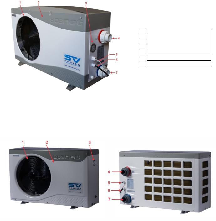
2. External Appearance
SN HP 55P and SN HP 90P
1 Fan protection grill ( exhaust side )
2 ABS/ASA plastic cabinet
3 Refrigerant pressure manometer
4 Water outlet
5 Data cable
6 Power cable
7 Water inlet
SN HP 120P
8
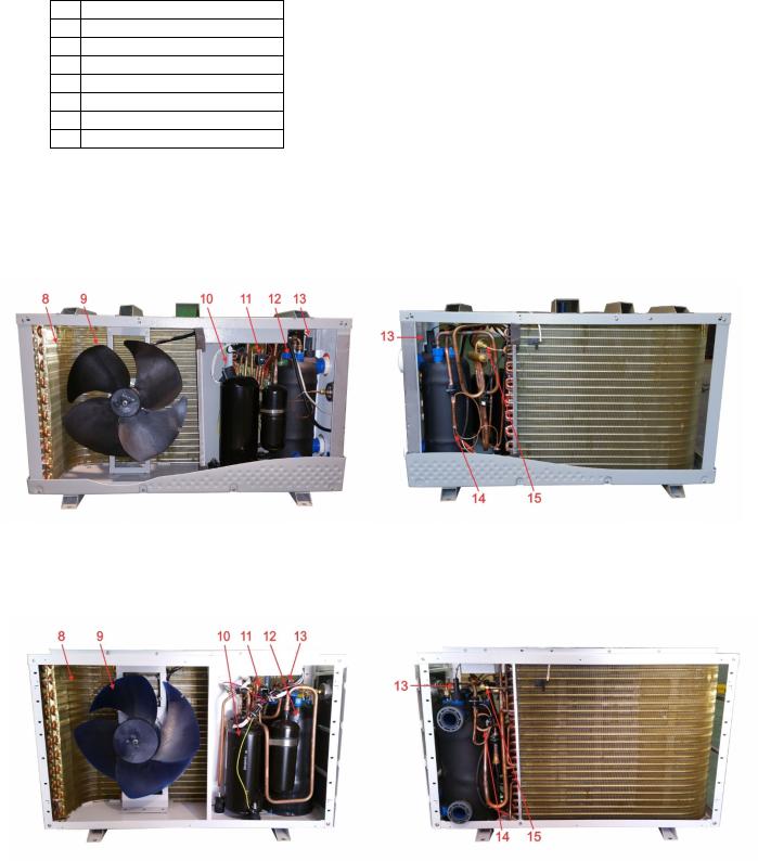
3. Internal appearance
(Front sheet cover and panel removed)
8 |
Evaporator |
9 |
Fan |
10 |
Compressor |
11 |
4 way valve |
12 |
Titanium in PVC heat exchanger |
13 |
Water flow switch |
14 |
Capillary |
15 |
Refrigerant charge valve |
SN HP 55 and SN HP 90
SN HP 120
9
 Loading...