

Page 1

Ultraview SL
™
Operations Manual
070-1150-01 Rev. AB
Page 2

©2011 Spacelabs Healthcare
Rx Only
!
All rights reserved. Contents of this publication may not be reproduced in any form without the written permission of
Spacelabs Healthcare. Products of Spacelabs Healthcare are covered by U.S. and foreign patents and/or pending
patents. Printed in U.S.A. Specifications and price change privileges are reserved.
Spacelabs Healthcare considers itself responsible for the effects on safety, reliability and performance of the
equipment only if:
• assembly operations, re-adjustments, modifications or repairs are carried out by persons authorized by
Spacelabs Healthcare, and
• the electrical installation of the relevant room complies with the requirements of the standard in force, and
• the equipment is used in accordance with the operations manual.
Spacelabs Healthcare will make available, on request, such circuit diagrams, component part lists, descriptions,
calibration instructions or other information which will assist appropriately qualified technical personnel to repair those
parts of the equipment which are classified by Spacelabs Healthcare as field repairable.
Spacelabs Healthcare is committed to providing comprehensive customer support beginning with your initial inquiry
through purchase, training, and service for the life of your Spacelabs Healthcare equipment.
CORPORATE OFFICES
U.S.A.
Spacelabs Healthcare, LLC
5150 220th Ave SE
Issaquah, WA 98029
Telephone: 425-657-7200
Telephone: 800-522-7025
Fax: 425-657-7212
Authorized EC Representative UNITED KINGDOM
Spacelabs Healthcare, Ltd.
1 Harforde Court
John Tate Road
Hertford, SG13 7NW
Hertfordshire, UK
Telephone: 44 (0) 1992 507730
Fax: 44 (0) 1992 501213
BirthNet, Clinical Browser, Data Shuttle, Flexport, Intesys, Mermaid, MOM, Multiview, PCIS, PCMS, PrintMaster,
Quicknet, Sensorwatch, TRU-CAP, TRU-CUFF, TruLink, Ultralite, Ultraview, Ultraview Care Network, Ultraview Clinical
Messenger, Ultraview Digital Telemetry, Ultraview SL, Uni-Pouch, UCW, Varitrend, Dynamic Network Access, DNA,
WinDNA, and XPREZZON are trademarks of Spacelabs Healthcare.
Other brands and product names are trademarks of their respective owners.
Caution:
US Federal law restricts the devices documented herein to sale by, or on the order of, a
physician.
Before use, carefully read the instructions, including all warnings and cautions.
Page 3

Table of Contents
Contents Page
Introduction
Overview. . . . . . . . . . . . . . . . . . . . . . . . . . . . . . . . . . . . . . . . . . . . . . . . . . . . . . . . . . . . . . . . . . . . . . . . . . . . . . . . . 1-1
Indications for Use . . . . . . . . . . . . . . . . . . . . . . . . . . . . . . . . . . . . . . . . . . . . . . . . . . . . . . . . . . . . . . . . . . . . . . . . . 1-1
Quickstarts . . . . . . . . . . . . . . . . . . . . . . . . . . . . . . . . . . . . . . . . . . . . . . . . . . . . . . . . . . . . . . . . . . . . . . . . . . . . . . . 1-3
System Components . . . . . . . . . . . . . . . . . . . . . . . . . . . . . . . . . . . . . . . . . . . . . . . . . . . . . . . . . . . . . . . . . . . . . . . 1-4
System Basics . . . . . . . . . . . . . . . . . . . . . . . . . . . . . . . . . . . . . . . . . . . . . . . . . . . . . . . . . . . . . . . . . . . . . . . . . . . . 1-9
Network Basics. . . . . . . . . . . . . . . . . . . . . . . . . . . . . . . . . . . . . . . . . . . . . . . . . . . . . . . . . . . . . . . . . . . . . . . . . . . 1-12
Alarm Watch . . . . . . . . . . . . . . . . . . . . . . . . . . . . . . . . . . . . . . . . . . . . . . . . . . . . . . . . . . . . . . . . . . . . . . . . . . . . . 1-14
Viewing Remote Parameters . . . . . . . . . . . . . . . . . . . . . . . . . . . . . . . . . . . . . . . . . . . . . . . . . . . . . . . . . . . . . . . . 1-14
Reviewing Remote Trends . . . . . . . . . . . . . . . . . . . . . . . . . . . . . . . . . . . . . . . . . . . . . . . . . . . . . . . . . . . . . . . . . . 1-16
Full Bed Review . . . . . . . . . . . . . . . . . . . . . . . . . . . . . . . . . . . . . . . . . . . . . . . . . . . . . . . . . . . . . . . . . . . . . . . . . . 1-17
Glossary of Terms
Bedside Monitors
Directory of Keys . . . . . . . . . . . . . . . . . . . . . . . . . . . . . . . . . . . . . . . . . . . . . . . . . . . . . . . . . . . . . . . . . . . . . . . . . . 3-1
Overview. . . . . . . . . . . . . . . . . . . . . . . . . . . . . . . . . . . . . . . . . . . . . . . . . . . . . . . . . . . . . . . . . . . . . . . . . . . . . . . . . 3-5
Display Detail . . . . . . . . . . . . . . . . . . . . . . . . . . . . . . . . . . . . . . . . . . . . . . . . . . . . . . . . . . . . . . . . . . . . . . . . . . . . 3-7
Identifying Special Applications . . . . . . . . . . . . . . . . . . . . . . . . . . . . . . . . . . . . . . . . . . . . . . . . . . . . . . . . . . . . . . . 3-7
Monitor Configuration Features . . . . . . . . . . . . . . . . . . . . . . . . . . . . . . . . . . . . . . . . . . . . . . . . . . . . . . . . . . . . . . . 3-8
Wireless Networking (SL2400/SL2600 Only) . . . . . . . . . . . . . . . . . . . . . . . . . . . . . . . . . . . . . . . . . . . . . . . . . . . . 3-14
Privileged Access Menus . . . . . . . . . . . . . . . . . . . . . . . . . . . . . . . . . . . . . . . . . . . . . . . . . . . . . . . . . . . . . . . . . . . 3-15
Data Shuttle Option . . . . . . . . . . . . . . . . . . . . . . . . . . . . . . . . . . . . . . . . . . . . . . . . . . . . . . . . . . . . . . . . . . . . . . . 3-16
Power and Battery Status (SL2400/SL2600 Only) . . . . . . . . . . . . . . . . . . . . . . . . . . . . . . . . . . . . . . . . . . . . . . . . 3-19
SL2400/SL2600 Monitor Connections . . . . . . . . . . . . . . . . . . . . . . . . . . . . . . . . . . . . . . . . . . . . . . . . . . . . . . . . . 3-21
Bedside Monitor Troubleshooting Guide . . . . . . . . . . . . . . . . . . . . . . . . . . . . . . . . . . . . . . . . . . . . . . . . . . . . . . . 3-24
Central Monitors
Directory of Keys . . . . . . . . . . . . . . . . . . . . . . . . . . . . . . . . . . . . . . . . . . . . . . . . . . . . . . . . . . . . . . . . . . . . . . . . . . 4-1
Overview. . . . . . . . . . . . . . . . . . . . . . . . . . . . . . . . . . . . . . . . . . . . . . . . . . . . . . . . . . . . . . . . . . . . . . . . . . . . . . . . . 4-5
Display Detail . . . . . . . . . . . . . . . . . . . . . . . . . . . . . . . . . . . . . . . . . . . . . . . . . . . . . . . . . . . . . . . . . . . . . . . . . . . . . 4-6
Central Monitor Setup. . . . . . . . . . . . . . . . . . . . . . . . . . . . . . . . . . . . . . . . . . . . . . . . . . . . . . . . . . . . . . . . . . . . . . . 4-6
Central Monitor Troubleshooting Guide . . . . . . . . . . . . . . . . . . . . . . . . . . . . . . . . . . . . . . . . . . . . . . . . . . . . . . . . 4-10
Dynamic Network Access (DNA)
Directory of Keys . . . . . . . . . . . . . . . . . . . . . . . . . . . . . . . . . . . . . . . . . . . . . . . . . . . . . . . . . . . . . . . . . . . . . . . . . . 5-1
Overview. . . . . . . . . . . . . . . . . . . . . . . . . . . . . . . . . . . . . . . . . . . . . . . . . . . . . . . . . . . . . . . . . . . . . . . . . . . . . . . . . 5-3
Connection View. . . . . . . . . . . . . . . . . . . . . . . . . . . . . . . . . . . . . . . . . . . . . . . . . . . . . . . . . . . . . . . . . . . . . . . . . . . 5-5
Program Neighborhood View . . . . . . . . . . . . . . . . . . . . . . . . . . . . . . . . . . . . . . . . . . . . . . . . . . . . . . . . . . . . . . . . . 5-6
Perioperative
Directory of Keys . . . . . . . . . . . . . . . . . . . . . . . . . . . . . . . . . . . . . . . . . . . . . . . . . . . . . . . . . . . . . . . . . . . . . . . . . . 6-1
Overview. . . . . . . . . . . . . . . . . . . . . . . . . . . . . . . . . . . . . . . . . . . . . . . . . . . . . . . . . . . . . . . . . . . . . . . . . . . . . . . . . 6-3
Identifying Perioperative Functions. . . . . . . . . . . . . . . . . . . . . . . . . . . . . . . . . . . . . . . . . . . . . . . . . . . . . . . . . . . . . 6-3
Start Case/End Case . . . . . . . . . . . . . . . . . . . . . . . . . . . . . . . . . . . . . . . . . . . . . . . . . . . . . . . . . . . . . . . . . . . . . . . 6-4
Secondary Display . . . . . . . . . . . . . . . . . . . . . . . . . . . . . . . . . . . . . . . . . . . . . . . . . . . . . . . . . . . . . . . . . . . . . . . . . 6-6
User Preference Configurations . . . . . . . . . . . . . . . . . . . . . . . . . . . . . . . . . . . . . . . . . . . . . . . . . . . . . . . . . . . . . . . 6-8
Perioperative Troubleshooting Guide . . . . . . . . . . . . . . . . . . . . . . . . . . . . . . . . . . . . . . . . . . . . . . . . . . . . . . . . . . 6-13
Ultraview SL Operations Manual i
Page 4

Table of Contents
Alarms
Directory of Keys . . . . . . . . . . . . . . . . . . . . . . . . . . . . . . . . . . . . . . . . . . . . . . . . . . . . . . . . . . . . . . . . . . . . . . . . . . 7-1
Overview. . . . . . . . . . . . . . . . . . . . . . . . . . . . . . . . . . . . . . . . . . . . . . . . . . . . . . . . . . . . . . . . . . . . . . . . . . . . . . . . . 7-5
Default Alarm Limits . . . . . . . . . . . . . . . . . . . . . . . . . . . . . . . . . . . . . . . . . . . . . . . . . . . . . . . . . . . . . . . . . . . . . . . . 7-7
Setting Alarm Limits . . . . . . . . . . . . . . . . . . . . . . . . . . . . . . . . . . . . . . . . . . . . . . . . . . . . . . . . . . . . . . . . . . . . . . . . 7-7
Identifying Alarm Levels . . . . . . . . . . . . . . . . . . . . . . . . . . . . . . . . . . . . . . . . . . . . . . . . . . . . . . . . . . . . . . . . . . . . . 7-8
Adjusting Alarm Tones and Key Tones . . . . . . . . . . . . . . . . . . . . . . . . . . . . . . . . . . . . . . . . . . . . . . . . . . . . . . . . 7-10
Silencing Alarm Tones and Alarm Suspend . . . . . . . . . . . . . . . . . . . . . . . . . . . . . . . . . . . . . . . . . . . . . . . . . . . . . 7-11
Controlling the Embedded Alarm Light (SL2400/SL2600 only) . . . . . . . . . . . . . . . . . . . . . . . . . . . . . . . . . . . . . . 7-12
Alarm Watch . . . . . . . . . . . . . . . . . . . . . . . . . . . . . . . . . . . . . . . . . . . . . . . . . . . . . . . . . . . . . . . . . . . . . . . . . . . . . 7-12
Automatic Recording of an Alarm . . . . . . . . . . . . . . . . . . . . . . . . . . . . . . . . . . . . . . . . . . . . . . . . . . . . . . . . . . . . . 7-15
Alarm Limit Review. . . . . . . . . . . . . . . . . . . . . . . . . . . . . . . . . . . . . . . . . . . . . . . . . . . . . . . . . . . . . . . . . . . . . . . . 7-16
Alarms Troubleshooting Guide . . . . . . . . . . . . . . . . . . . . . . . . . . . . . . . . . . . . . . . . . . . . . . . . . . . . . . . . . . . . . . . 7-17
Admit/Discharge
Directory of Keys . . . . . . . . . . . . . . . . . . . . . . . . . . . . . . . . . . . . . . . . . . . . . . . . . . . . . . . . . . . . . . . . . . . . . . . . . . 8-1
Overview. . . . . . . . . . . . . . . . . . . . . . . . . . . . . . . . . . . . . . . . . . . . . . . . . . . . . . . . . . . . . . . . . . . . . . . . . . . . . . . . . 8-3
Changing or Entering New Patient Data. . . . . . . . . . . . . . . . . . . . . . . . . . . . . . . . . . . . . . . . . . . . . . . . . . . . . . . . . 8-3
Discharging a Patient . . . . . . . . . . . . . . . . . . . . . . . . . . . . . . . . . . . . . . . . . . . . . . . . . . . . . . . . . . . . . . . . . . . . . . . 8-7
Scanning Barcoded Demographic Data . . . . . . . . . . . . . . . . . . . . . . . . . . . . . . . . . . . . . . . . . . . . . . . . . . . . . . . . . 8-7
Admit/Discharge Troubleshooting Guide . . . . . . . . . . . . . . . . . . . . . . . . . . . . . . . . . . . . . . . . . . . . . . . . . . . . . . . 8-11
Printing
Directory of Keys . . . . . . . . . . . . . . . . . . . . . . . . . . . . . . . . . . . . . . . . . . . . . . . . . . . . . . . . . . . . . . . . . . . . . . . . . . 9-1
Overview. . . . . . . . . . . . . . . . . . . . . . . . . . . . . . . . . . . . . . . . . . . . . . . . . . . . . . . . . . . . . . . . . . . . . . . . . . . . . . . . . 9-5
Printing Configurations . . . . . . . . . . . . . . . . . . . . . . . . . . . . . . . . . . . . . . . . . . . . . . . . . . . . . . . . . . . . . . . . . . . . . . 9-6
Printing Priorities . . . . . . . . . . . . . . . . . . . . . . . . . . . . . . . . . . . . . . . . . . . . . . . . . . . . . . . . . . . . . . . . . . . . . . . . . . 9-7
90449 Printer Module . . . . . . . . . . . . . . . . . . . . . . . . . . . . . . . . . . . . . . . . . . . . . . . . . . . . . . . . . . . . . . . . . . . . . . . 9-8
90469 System Printer Module . . . . . . . . . . . . . . . . . . . . . . . . . . . . . . . . . . . . . . . . . . . . . . . . . . . . . . . . . . . . . . . 9-11
SL2400/SL2600 Printer (optional) . . . . . . . . . . . . . . . . . . . . . . . . . . . . . . . . . . . . . . . . . . . . . . . . . . . . . . . . . . . . 9-13
PrintMaster . . . . . . . . . . . . . . . . . . . . . . . . . . . . . . . . . . . . . . . . . . . . . . . . . . . . . . . . . . . . . . . . . . . . . . . . . . . . . . 9-14
Printer Key Functions . . . . . . . . . . . . . . . . . . . . . . . . . . . . . . . . . . . . . . . . . . . . . . . . . . . . . . . . . . . . . . . . . . . . . . 9-17
Selecting Print Duration . . . . . . . . . . . . . . . . . . . . . . . . . . . . . . . . . . . . . . . . . . . . . . . . . . . . . . . . . . . . . . . . . . . . 9-18
Selecting Recording Destination. . . . . . . . . . . . . . . . . . . . . . . . . . . . . . . . . . . . . . . . . . . . . . . . . . . . . . . . . . . . . . 9-18
Recording Alarms . . . . . . . . . . . . . . . . . . . . . . . . . . . . . . . . . . . . . . . . . . . . . . . . . . . . . . . . . . . . . . . . . . . . . . . . . 9-19
Printing via Monitors . . . . . . . . . . . . . . . . . . . . . . . . . . . . . . . . . . . . . . . . . . . . . . . . . . . . . . . . . . . . . . . . . . . . . . . 9-19
Defining Preselected Recording Keys . . . . . . . . . . . . . . . . . . . . . . . . . . . . . . . . . . . . . . . . . . . . . . . . . . . . . . . . . 9-21
Paper Out Conditions . . . . . . . . . . . . . . . . . . . . . . . . . . . . . . . . . . . . . . . . . . . . . . . . . . . . . . . . . . . . . . . . . . . . . . 9-22
Vitals Report (SL2400/SL2600 monitors only) . . . . . . . . . . . . . . . . . . . . . . . . . . . . . . . . . . . . . . . . . . . . . . . . . . . 9-22
Printing Troubleshooting Guide . . . . . . . . . . . . . . . . . . . . . . . . . . . . . . . . . . . . . . . . . . . . . . . . . . . . . . . . . . . . . . 9-24
ECG
Directory of Keys . . . . . . . . . . . . . . . . . . . . . . . . . . . . . . . . . . . . . . . . . . . . . . . . . . . . . . . . . . . . . . . . . . . . . . . . . 10-1
Overview. . . . . . . . . . . . . . . . . . . . . . . . . . . . . . . . . . . . . . . . . . . . . . . . . . . . . . . . . . . . . . . . . . . . . . . . . . . . . . . . 10-5
Warnings and Cautions . . . . . . . . . . . . . . . . . . . . . . . . . . . . . . . . . . . . . . . . . . . . . . . . . . . . . . . . . . . . . . . . . . . . 10-6
ECG Setup . . . . . . . . . . . . . . . . . . . . . . . . . . . . . . . . . . . . . . . . . . . . . . . . . . . . . . . . . . . . . . . . . . . . . . . . . . . . . . 10-6
Display Detail . . . . . . . . . . . . . . . . . . . . . . . . . . . . . . . . . . . . . . . . . . . . . . . . . . . . . . . . . . . . . . . . . . . . . . . . . . . 10-11
Selecting ADULT or INFANT Mode . . . . . . . . . . . . . . . . . . . . . . . . . . . . . . . . . . . . . . . . . . . . . . . . . . . . . . . . . . 10-15
Monitoring Patients with Pacemakers. . . . . . . . . . . . . . . . . . . . . . . . . . . . . . . . . . . . . . . . . . . . . . . . . . . . . . . . . 10-15
Enabling and Adjusting Alarms. . . . . . . . . . . . . . . . . . . . . . . . . . . . . . . . . . . . . . . . . . . . . . . . . . . . . . . . . . . . . . 10-17
Selecting ECG Leads . . . . . . . . . . . . . . . . . . . . . . . . . . . . . . . . . . . . . . . . . . . . . . . . . . . . . . . . . . . . . . . . . . . . . 10-19
Adjusting Waveform Size . . . . . . . . . . . . . . . . . . . . . . . . . . . . . . . . . . . . . . . . . . . . . . . . . . . . . . . . . . . . . . . . . . 10-20
Adjusting Sweep Speed . . . . . . . . . . . . . . . . . . . . . . . . . . . . . . . . . . . . . . . . . . . . . . . . . . . . . . . . . . . . . . . . . . . 10-21
Adjusting Tones . . . . . . . . . . . . . . . . . . . . . . . . . . . . . . . . . . . . . . . . . . . . . . . . . . . . . . . . . . . . . . . . . . . . . . . . . 10-21
Changing the Display Resolution . . . . . . . . . . . . . . . . . . . . . . . . . . . . . . . . . . . . . . . . . . . . . . . . . . . . . . . . . . . . 10-22
Selecting Primary and Alternate Heart Rate Sources. . . . . . . . . . . . . . . . . . . . . . . . . . . . . . . . . . . . . . . . . . . . . 10-22
Suspending/Resuming ECG Processing . . . . . . . . . . . . . . . . . . . . . . . . . . . . . . . . . . . . . . . . . . . . . . . . . . . . . . 10-23
Ultraview SL Operations Manual ii
Page 5

Table of Contents
Printing ECG Data . . . . . . . . . . . . . . . . . . . . . . . . . . . . . . . . . . . . . . . . . . . . . . . . . . . . . . . . . . . . . . . . . . . . . . . 10-24
Restoring Default Settings . . . . . . . . . . . . . . . . . . . . . . . . . . . . . . . . . . . . . . . . . . . . . . . . . . . . . . . . . . . . . . . . . 10-24
ECG Problem Solving. . . . . . . . . . . . . . . . . . . . . . . . . . . . . . . . . . . . . . . . . . . . . . . . . . . . . . . . . . . . . . . . . . . . . 10-25
ECG Alarm Delays . . . . . . . . . . . . . . . . . . . . . . . . . . . . . . . . . . . . . . . . . . . . . . . . . . . . . . . . . . . . . . . . . . . . . . . 10-26
ECG Troubleshooting Guide . . . . . . . . . . . . . . . . . . . . . . . . . . . . . . . . . . . . . . . . . . . . . . . . . . . . . . . . . . . . . . . 10-27
Arrhythmia
Directory of Keys . . . . . . . . . . . . . . . . . . . . . . . . . . . . . . . . . . . . . . . . . . . . . . . . . . . . . . . . . . . . . . . . . . . . . . . . . 11-1
Overview. . . . . . . . . . . . . . . . . . . . . . . . . . . . . . . . . . . . . . . . . . . . . . . . . . . . . . . . . . . . . . . . . . . . . . . . . . . . . . . . 11-3
Setting Up Arrhythmia Monitoring. . . . . . . . . . . . . . . . . . . . . . . . . . . . . . . . . . . . . . . . . . . . . . . . . . . . . . . . . . . . . 11-4
Classifying Events . . . . . . . . . . . . . . . . . . . . . . . . . . . . . . . . . . . . . . . . . . . . . . . . . . . . . . . . . . . . . . . . . . . . . . . . 11-5
Learning and Relearning . . . . . . . . . . . . . . . . . . . . . . . . . . . . . . . . . . . . . . . . . . . . . . . . . . . . . . . . . . . . . . . . . . . 11-6
Automatic Dominant Class Update. . . . . . . . . . . . . . . . . . . . . . . . . . . . . . . . . . . . . . . . . . . . . . . . . . . . . . . . . . . . 11-7
Display Detail . . . . . . . . . . . . . . . . . . . . . . . . . . . . . . . . . . . . . . . . . . . . . . . . . . . . . . . . . . . . . . . . . . . . . . . . . . . . 11-8
Enabling and Adjusting Alarms. . . . . . . . . . . . . . . . . . . . . . . . . . . . . . . . . . . . . . . . . . . . . . . . . . . . . . . . . . . . . . . 11-8
Reviewing Arrhythmias. . . . . . . . . . . . . . . . . . . . . . . . . . . . . . . . . . . . . . . . . . . . . . . . . . . . . . . . . . . . . . . . . . . . . 11-9
Clearing a Class or Event. . . . . . . . . . . . . . . . . . . . . . . . . . . . . . . . . . . . . . . . . . . . . . . . . . . . . . . . . . . . . . . . . . 11-10
Merging Classes or Trends. . . . . . . . . . . . . . . . . . . . . . . . . . . . . . . . . . . . . . . . . . . . . . . . . . . . . . . . . . . . . . . . . 11-11
Arrhythmia Trend Graphs. . . . . . . . . . . . . . . . . . . . . . . . . . . . . . . . . . . . . . . . . . . . . . . . . . . . . . . . . . . . . . . . . . 11-12
Printing Arrhythmia Data. . . . . . . . . . . . . . . . . . . . . . . . . . . . . . . . . . . . . . . . . . . . . . . . . . . . . . . . . . . . . . . . . . . 11-15
Arrhythmia Problem Solving . . . . . . . . . . . . . . . . . . . . . . . . . . . . . . . . . . . . . . . . . . . . . . . . . . . . . . . . . . . . . . . . 11-16
Arrhythmia Troubleshooting Guide. . . . . . . . . . . . . . . . . . . . . . . . . . . . . . . . . . . . . . . . . . . . . . . . . . . . . . . . . . . 11-18
ST Analysis
Directory of Keys . . . . . . . . . . . . . . . . . . . . . . . . . . . . . . . . . . . . . . . . . . . . . . . . . . . . . . . . . . . . . . . . . . . . . . . . . 12-1
Overview. . . . . . . . . . . . . . . . . . . . . . . . . . . . . . . . . . . . . . . . . . . . . . . . . . . . . . . . . . . . . . . . . . . . . . . . . . . . . . . . 12-3
Display Detail . . . . . . . . . . . . . . . . . . . . . . . . . . . . . . . . . . . . . . . . . . . . . . . . . . . . . . . . . . . . . . . . . . . . . . . . . . . . 12-4
Setting Up ST Monitoring . . . . . . . . . . . . . . . . . . . . . . . . . . . . . . . . . . . . . . . . . . . . . . . . . . . . . . . . . . . . . . . . . . . 12-6
Enabling and Adjusting Alarms. . . . . . . . . . . . . . . . . . . . . . . . . . . . . . . . . . . . . . . . . . . . . . . . . . . . . . . . . . . . . . . 12-7
Selecting Leads for ST Alarms . . . . . . . . . . . . . . . . . . . . . . . . . . . . . . . . . . . . . . . . . . . . . . . . . . . . . . . . . . . . . . . 12-8
Reviewing ST Data. . . . . . . . . . . . . . . . . . . . . . . . . . . . . . . . . . . . . . . . . . . . . . . . . . . . . . . . . . . . . . . . . . . . . . . . 12-9
Clearing ST Data . . . . . . . . . . . . . . . . . . . . . . . . . . . . . . . . . . . . . . . . . . . . . . . . . . . . . . . . . . . . . . . . . . . . . . . . 12-10
Viewing ST Trends . . . . . . . . . . . . . . . . . . . . . . . . . . . . . . . . . . . . . . . . . . . . . . . . . . . . . . . . . . . . . . . . . . . . . . . 12-10
Printing ST Data . . . . . . . . . . . . . . . . . . . . . . . . . . . . . . . . . . . . . . . . . . . . . . . . . . . . . . . . . . . . . . . . . . . . . . . . . 12-12
Displaying Real-Time ST Trends . . . . . . . . . . . . . . . . . . . . . . . . . . . . . . . . . . . . . . . . . . . . . . . . . . . . . . . . . . . . 12-13
ST Analysis Troubleshooting Guide . . . . . . . . . . . . . . . . . . . . . . . . . . . . . . . . . . . . . . . . . . . . . . . . . . . . . . . . . . 12-14
12-Lead Diagnostics
Directory of Keys . . . . . . . . . . . . . . . . . . . . . . . . . . . . . . . . . . . . . . . . . . . . . . . . . . . . . . . . . . . . . . . . . . . . . . . . . 13-1
Overview. . . . . . . . . . . . . . . . . . . . . . . . . . . . . . . . . . . . . . . . . . . . . . . . . . . . . . . . . . . . . . . . . . . . . . . . . . . . . . . . 13-3
Display Detail . . . . . . . . . . . . . . . . . . . . . . . . . . . . . . . . . . . . . . . . . . . . . . . . . . . . . . . . . . . . . . . . . . . . . . . . . . . . 13-4
Acquiring and Printing 12-Lead Reports. . . . . . . . . . . . . . . . . . . . . . . . . . . . . . . . . . . . . . . . . . . . . . . . . . . . . . . . 13-4
Saving and Clearing 12-Lead Reports . . . . . . . . . . . . . . . . . . . . . . . . . . . . . . . . . . . . . . . . . . . . . . . . . . . . . . . . . 13-5
Sending 12-Lead ECG Reports . . . . . . . . . . . . . . . . . . . . . . . . . . . . . . . . . . . . . . . . . . . . . . . . . . . . . . . . . . . . . . 13-6
Viewing the Report Directory . . . . . . . . . . . . . . . . . . . . . . . . . . . . . . . . . . . . . . . . . . . . . . . . . . . . . . . . . . . . . . . . 13-7
Entering Patient Demographics . . . . . . . . . . . . . . . . . . . . . . . . . . . . . . . . . . . . . . . . . . . . . . . . . . . . . . . . . . . . . . 13-8
Respiration
Directory of Keys . . . . . . . . . . . . . . . . . . . . . . . . . . . . . . . . . . . . . . . . . . . . . . . . . . . . . . . . . . . . . . . . . . . . . . . . . 14-1
Overview. . . . . . . . . . . . . . . . . . . . . . . . . . . . . . . . . . . . . . . . . . . . . . . . . . . . . . . . . . . . . . . . . . . . . . . . . . . . . . . . 14-3
Warnings and Cautions . . . . . . . . . . . . . . . . . . . . . . . . . . . . . . . . . . . . . . . . . . . . . . . . . . . . . . . . . . . . . . . . . . . . 14-4
Setting Up Respiration Monitoring . . . . . . . . . . . . . . . . . . . . . . . . . . . . . . . . . . . . . . . . . . . . . . . . . . . . . . . . . . . . 14-4
Display Detail . . . . . . . . . . . . . . . . . . . . . . . . . . . . . . . . . . . . . . . . . . . . . . . . . . . . . . . . . . . . . . . . . . . . . . . . . . . . 14-5
Selecting ADULT or INFANT Mode . . . . . . . . . . . . . . . . . . . . . . . . . . . . . . . . . . . . . . . . . . . . . . . . . . . . . . . . . . . 14-6
Adjusting Respiration Sensitivity. . . . . . . . . . . . . . . . . . . . . . . . . . . . . . . . . . . . . . . . . . . . . . . . . . . . . . . . . . . . . . 14-6
Using the Cardiovascular Artifact Filter . . . . . . . . . . . . . . . . . . . . . . . . . . . . . . . . . . . . . . . . . . . . . . . . . . . . . . . . 14-6
Selecting Respiration Leads. . . . . . . . . . . . . . . . . . . . . . . . . . . . . . . . . . . . . . . . . . . . . . . . . . . . . . . . . . . . . . . . . 14-7
Ultraview SL Operations Manual iii
Page 6

Table of Contents
Enabling and Adjusting Alarms. . . . . . . . . . . . . . . . . . . . . . . . . . . . . . . . . . . . . . . . . . . . . . . . . . . . . . . . . . . . . . . 14-9
Selecting Other Settings. . . . . . . . . . . . . . . . . . . . . . . . . . . . . . . . . . . . . . . . . . . . . . . . . . . . . . . . . . . . . . . . . . . . 14-9
Printing Respiration Waveforms . . . . . . . . . . . . . . . . . . . . . . . . . . . . . . . . . . . . . . . . . . . . . . . . . . . . . . . . . . . . . 14-10
Respiration Alarm Delays . . . . . . . . . . . . . . . . . . . . . . . . . . . . . . . . . . . . . . . . . . . . . . . . . . . . . . . . . . . . . . . . . . 14-11
Respiration Troubleshooting Guide . . . . . . . . . . . . . . . . . . . . . . . . . . . . . . . . . . . . . . . . . . . . . . . . . . . . . . . . . . 14-12
Varitrend
Directory of Keys . . . . . . . . . . . . . . . . . . . . . . . . . . . . . . . . . . . . . . . . . . . . . . . . . . . . . . . . . . . . . . . . . . . . . . . . . 15-1
Introduction. . . . . . . . . . . . . . . . . . . . . . . . . . . . . . . . . . . . . . . . . . . . . . . . . . . . . . . . . . . . . . . . . . . . . . . . . . . . . . 15-3
Configuring Varitrend Graphs. . . . . . . . . . . . . . . . . . . . . . . . . . . . . . . . . . . . . . . . . . . . . . . . . . . . . . . . . . . . . . . . 15-3
Printing Varitrend Graphs . . . . . . . . . . . . . . . . . . . . . . . . . . . . . . . . . . . . . . . . . . . . . . . . . . . . . . . . . . . . . . . . . . . 15-9
Varitrend Troubleshooting Guide. . . . . . . . . . . . . . . . . . . . . . . . . . . . . . . . . . . . . . . . . . . . . . . . . . . . . . . . . . . . 15-10
NIBP
Directory of Keys . . . . . . . . . . . . . . . . . . . . . . . . . . . . . . . . . . . . . . . . . . . . . . . . . . . . . . . . . . . . . . . . . . . . . . . . . 16-1
Overview. . . . . . . . . . . . . . . . . . . . . . . . . . . . . . . . . . . . . . . . . . . . . . . . . . . . . . . . . . . . . . . . . . . . . . . . . . . . . . . . 16-3
Warnings and Cautions . . . . . . . . . . . . . . . . . . . . . . . . . . . . . . . . . . . . . . . . . . . . . . . . . . . . . . . . . . . . . . . . . . . . 16-4
Selecting ADULT or NEONATAL Mode . . . . . . . . . . . . . . . . . . . . . . . . . . . . . . . . . . . . . . . . . . . . . . . . . . . . . . . . 16-4
Setting Up NIBP Monitoring . . . . . . . . . . . . . . . . . . . . . . . . . . . . . . . . . . . . . . . . . . . . . . . . . . . . . . . . . . . . . . . . . 16-5
Display Detail . . . . . . . . . . . . . . . . . . . . . . . . . . . . . . . . . . . . . . . . . . . . . . . . . . . . . . . . . . . . . . . . . . . . . . . . . . . . 16-6
Reviewing NIBP Readings . . . . . . . . . . . . . . . . . . . . . . . . . . . . . . . . . . . . . . . . . . . . . . . . . . . . . . . . . . . . . . . . . . 16-7
Printing NIBP Readings . . . . . . . . . . . . . . . . . . . . . . . . . . . . . . . . . . . . . . . . . . . . . . . . . . . . . . . . . . . . . . . . . . . . 16-8
Taking NIBP Readings and Venous Stasis . . . . . . . . . . . . . . . . . . . . . . . . . . . . . . . . . . . . . . . . . . . . . . . . . . . . . 16-8
Enabling and Adjusting Alarms. . . . . . . . . . . . . . . . . . . . . . . . . . . . . . . . . . . . . . . . . . . . . . . . . . . . . . . . . . . . . . 16-13
NIBP Alarm Delays. . . . . . . . . . . . . . . . . . . . . . . . . . . . . . . . . . . . . . . . . . . . . . . . . . . . . . . . . . . . . . . . . . . . . . . 16-14
NIBP Troubleshooting Guide . . . . . . . . . . . . . . . . . . . . . . . . . . . . . . . . . . . . . . . . . . . . . . . . . . . . . . . . . . . . . . . 16-15
SpO
2
Directory of Keys — Spacelabs Healthcare SpO2 Technology . . . . . . . . . . . . . . . . . . . . . . . . . . . . . . . . . . . . . . 17-1
Directory of Keys — Nellcor OxiMax SpO
Directory of Keys — Masimo SET SpO2 Technology. . . . . . . . . . . . . . . . . . . . . . . . . . . . . . . . . . . . . . . . . . . . . . 17-3
Overview. . . . . . . . . . . . . . . . . . . . . . . . . . . . . . . . . . . . . . . . . . . . . . . . . . . . . . . . . . . . . . . . . . . . . . . . . . . . . . . . 17-5
Warnings and Cautions . . . . . . . . . . . . . . . . . . . . . . . . . . . . . . . . . . . . . . . . . . . . . . . . . . . . . . . . . . . . . . . . . . . . 17-7
Setting Up SpO
Monitoring . . . . . . . . . . . . . . . . . . . . . . . . . . . . . . . . . . . . . . . . . . . . . . . . . . . . . . . . . . . . . . . . . 17-8
2
Ensuring Accurate SpO2 Monitoring. . . . . . . . . . . . . . . . . . . . . . . . . . . . . . . . . . . . . . . . . . . . . . . . . . . . . . . . . . .17-9
Display Detail . . . . . . . . . . . . . . . . . . . . . . . . . . . . . . . . . . . . . . . . . . . . . . . . . . . . . . . . . . . . . . . . . . . . . . . . . . . 17-11
Using the Sensorwatch Feature . . . . . . . . . . . . . . . . . . . . . . . . . . . . . . . . . . . . . . . . . . . . . . . . . . . . . . . . . . . . . 17-12
NO PULSE Alarm Indicator (Nellcor OxiMax Technology) . . . . . . . . . . . . . . . . . . . . . . . . . . . . . . . . . . . . . . . . . 17-13
Enabling and Adjusting Alarms. . . . . . . . . . . . . . . . . . . . . . . . . . . . . . . . . . . . . . . . . . . . . . . . . . . . . . . . . . . . . . 17-13
Data Averaging. . . . . . . . . . . . . . . . . . . . . . . . . . . . . . . . . . . . . . . . . . . . . . . . . . . . . . . . . . . . . . . . . . . . . . . . . . 17-16
Sensitivity and FAST SAT (Masimo SET Technology). . . . . . . . . . . . . . . . . . . . . . . . . . . . . . . . . . . . . . . . . . . . 17-17
Using SpO
with Intra-Aortic Balloon Pumps . . . . . . . . . . . . . . . . . . . . . . . . . . . . . . . . . . . . . . . . . . . . . . . . . . . 17-18
2
Adjusting Tone Volume . . . . . . . . . . . . . . . . . . . . . . . . . . . . . . . . . . . . . . . . . . . . . . . . . . . . . . . . . . . . . . . . . . . 17-19
Adjusting Waveform Size . . . . . . . . . . . . . . . . . . . . . . . . . . . . . . . . . . . . . . . . . . . . . . . . . . . . . . . . . . . . . . . . . . 17-19
Viewing Pulse Rate . . . . . . . . . . . . . . . . . . . . . . . . . . . . . . . . . . . . . . . . . . . . . . . . . . . . . . . . . . . . . . . . . . . . . . 17-20
Suspending/Resuming SpO
Processing. . . . . . . . . . . . . . . . . . . . . . . . . . . . . . . . . . . . . . . . . . . . . . . . . . . . . . 17-20
2
Suspend on NIBP . . . . . . . . . . . . . . . . . . . . . . . . . . . . . . . . . . . . . . . . . . . . . . . . . . . . . . . . . . . . . . . . . . . . . . . . 17-21
Printing SpO
Waveforms. . . . . . . . . . . . . . . . . . . . . . . . . . . . . . . . . . . . . . . . . . . . . . . . . . . . . . . . . . . . . . . . . . 17-21
2
Status Messages . . . . . . . . . . . . . . . . . . . . . . . . . . . . . . . . . . . . . . . . . . . . . . . . . . . . . . . . . . . . . . . . . . . . . . . . 17-22
Status Messages — Nellcor OxiMax Technology. . . . . . . . . . . . . . . . . . . . . . . . . . . . . . . . . . . . . . . . . . . . . . . . 17-24
Status Messages — Masimo SET Technology . . . . . . . . . . . . . . . . . . . . . . . . . . . . . . . . . . . . . . . . . . . . . . . . . 17-26
Sensors . . . . . . . . . . . . . . . . . . . . . . . . . . . . . . . . . . . . . . . . . . . . . . . . . . . . . . . . . . . . . . . . . . . . . . . . . . . . . . . 17-27
Alarm Delays. . . . . . . . . . . . . . . . . . . . . . . . . . . . . . . . . . . . . . . . . . . . . . . . . . . . . . . . . . . . . . . . . . . . . . . 17-28
SpO
2
SpO2 Troubleshooting Guide . . . . . . . . . . . . . . . . . . . . . . . . . . . . . . . . . . . . . . . . . . . . . . . . . . . . . . . . . . . . . . . 17-29
Technology. . . . . . . . . . . . . . . . . . . . . . . . . . . . . . . . . . . . . . . . . . . . 17-2
2
Ultraview SL Operations Manual iv
Page 7

Table of Contents
Digital Telemetry
Directory of Keys . . . . . . . . . . . . . . . . . . . . . . . . . . . . . . . . . . . . . . . . . . . . . . . . . . . . . . . . . . . . . . . . . . . . . . . . . 18-1
Overview. . . . . . . . . . . . . . . . . . . . . . . . . . . . . . . . . . . . . . . . . . . . . . . . . . . . . . . . . . . . . . . . . . . . . . . . . . . . . . . . 18-3
Warnings and Cautions . . . . . . . . . . . . . . . . . . . . . . . . . . . . . . . . . . . . . . . . . . . . . . . . . . . . . . . . . . . . . . . . . . . . 18-4
Intended Use . . . . . . . . . . . . . . . . . . . . . . . . . . . . . . . . . . . . . . . . . . . . . . . . . . . . . . . . . . . . . . . . . . . . . . . . . . . . 18-6
Digital Telemetry System Components . . . . . . . . . . . . . . . . . . . . . . . . . . . . . . . . . . . . . . . . . . . . . . . . . . . . . . . . 18-7
Display Detail . . . . . . . . . . . . . . . . . . . . . . . . . . . . . . . . . . . . . . . . . . . . . . . . . . . . . . . . . . . . . . . . . . . . . . . . . . . 18-12
Setting up Telemetry Monitoring. . . . . . . . . . . . . . . . . . . . . . . . . . . . . . . . . . . . . . . . . . . . . . . . . . . . . . . . . . . . . 18-15
Enabling and Adjusting Alarms. . . . . . . . . . . . . . . . . . . . . . . . . . . . . . . . . . . . . . . . . . . . . . . . . . . . . . . . . . . . . . 18-16
Discharging a Patient and Acknowledging Signal Loss . . . . . . . . . . . . . . . . . . . . . . . . . . . . . . . . . . . . . . . . . . . 18-16
Controlling Patient-Initiated Recordings . . . . . . . . . . . . . . . . . . . . . . . . . . . . . . . . . . . . . . . . . . . . . . . . . . . . . . . 18-17
Multiparameter Telemetry (NIBP). . . . . . . . . . . . . . . . . . . . . . . . . . . . . . . . . . . . . . . . . . . . . . . . . . . . . . . . . . . . 18-18
Status Messages . . . . . . . . . . . . . . . . . . . . . . . . . . . . . . . . . . . . . . . . . . . . . . . . . . . . . . . . . . . . . . . . . . . . . . . . 18-22
NIBP Troubleshooting Guide . . . . . . . . . . . . . . . . . . . . . . . . . . . . . . . . . . . . . . . . . . . . . . . . . . . . . . . . . . . . . . . 18-24
Temperature
Directory of Keys . . . . . . . . . . . . . . . . . . . . . . . . . . . . . . . . . . . . . . . . . . . . . . . . . . . . . . . . . . . . . . . . . . . . . . . . . 19-1
Overview. . . . . . . . . . . . . . . . . . . . . . . . . . . . . . . . . . . . . . . . . . . . . . . . . . . . . . . . . . . . . . . . . . . . . . . . . . . . . . . . 19-3
Setting Up Temperature Monitoring . . . . . . . . . . . . . . . . . . . . . . . . . . . . . . . . . . . . . . . . . . . . . . . . . . . . . . . . . . . 19-3
Display Detail . . . . . . . . . . . . . . . . . . . . . . . . . . . . . . . . . . . . . . . . . . . . . . . . . . . . . . . . . . . . . . . . . . . . . . . . . . . . 19-4
Enabling and Adjusting Alarms. . . . . . . . . . . . . . . . . . . . . . . . . . . . . . . . . . . . . . . . . . . . . . . . . . . . . . . . . . . . . . . 19-4
Setting Temperature Sensor Site Labels . . . . . . . . . . . . . . . . . . . . . . . . . . . . . . . . . . . . . . . . . . . . . . . . . . . . . . . 19-5
Printing Temperature Readings . . . . . . . . . . . . . . . . . . . . . . . . . . . . . . . . . . . . . . . . . . . . . . . . . . . . . . . . . . . . . . 19-5
Temperature Alarm Delays. . . . . . . . . . . . . . . . . . . . . . . . . . . . . . . . . . . . . . . . . . . . . . . . . . . . . . . . . . . . . . . . . . 19-5
Temperature Troubleshooting Guide . . . . . . . . . . . . . . . . . . . . . . . . . . . . . . . . . . . . . . . . . . . . . . . . . . . . . . . . . . 19-6
Pressure
Directory of Keys . . . . . . . . . . . . . . . . . . . . . . . . . . . . . . . . . . . . . . . . . . . . . . . . . . . . . . . . . . . . . . . . . . . . . . . . . 20-1
Overview. . . . . . . . . . . . . . . . . . . . . . . . . . . . . . . . . . . . . . . . . . . . . . . . . . . . . . . . . . . . . . . . . . . . . . . . . . . . . . . . 20-3
Setting Up Pressure Monitoring and Zeroing the Transducer . . . . . . . . . . . . . . . . . . . . . . . . . . . . . . . . . . . . . . . 20-4
Display Detail . . . . . . . . . . . . . . . . . . . . . . . . . . . . . . . . . . . . . . . . . . . . . . . . . . . . . . . . . . . . . . . . . . . . . . . . . . . . 20-6
Enabling and Adjusting Alarms. . . . . . . . . . . . . . . . . . . . . . . . . . . . . . . . . . . . . . . . . . . . . . . . . . . . . . . . . . . . . . . 20-7
Adjusting Waveform Size and Sweep Speed . . . . . . . . . . . . . . . . . . . . . . . . . . . . . . . . . . . . . . . . . . . . . . . . . . . . 20-8
Displaying Waveforms with Scales. . . . . . . . . . . . . . . . . . . . . . . . . . . . . . . . . . . . . . . . . . . . . . . . . . . . . . . . . . . . 20-8
Selecting the Waveform Measurement Value . . . . . . . . . . . . . . . . . . . . . . . . . . . . . . . . . . . . . . . . . . . . . . . . . . 20-10
Printing Pressure Waveforms. . . . . . . . . . . . . . . . . . . . . . . . . . . . . . . . . . . . . . . . . . . . . . . . . . . . . . . . . . . . . . . 20-11
Setting Artifact Rejection . . . . . . . . . . . . . . . . . . . . . . . . . . . . . . . . . . . . . . . . . . . . . . . . . . . . . . . . . . . . . . . . . . 20-11
Selecting a Filter Frequency. . . . . . . . . . . . . . . . . . . . . . . . . . . . . . . . . . . . . . . . . . . . . . . . . . . . . . . . . . . . . . . . 20-12
Pulse Pressure Variation . . . . . . . . . . . . . . . . . . . . . . . . . . . . . . . . . . . . . . . . . . . . . . . . . . . . . . . . . . . . . . . . . . 20-12
Factory-Default Pressure Alarm Settings . . . . . . . . . . . . . . . . . . . . . . . . . . . . . . . . . . . . . . . . . . . . . . . . . . . . . . 20-15
IBP Alarm Delays . . . . . . . . . . . . . . . . . . . . . . . . . . . . . . . . . . . . . . . . . . . . . . . . . . . . . . . . . . . . . . . . . . . . . . . . 20-18
Invasive Pressure Troubleshooting Guide . . . . . . . . . . . . . . . . . . . . . . . . . . . . . . . . . . . . . . . . . . . . . . . . . . . . . 20-19
Cardiac Output
Directory of Keys . . . . . . . . . . . . . . . . . . . . . . . . . . . . . . . . . . . . . . . . . . . . . . . . . . . . . . . . . . . . . . . . . . . . . . . . . 21-1
Overview. . . . . . . . . . . . . . . . . . . . . . . . . . . . . . . . . . . . . . . . . . . . . . . . . . . . . . . . . . . . . . . . . . . . . . . . . . . . . . . . 21-3
Setting Up Cardiac Output Monitoring . . . . . . . . . . . . . . . . . . . . . . . . . . . . . . . . . . . . . . . . . . . . . . . . . . . . . . . . . 21-4
Display Detail . . . . . . . . . . . . . . . . . . . . . . . . . . . . . . . . . . . . . . . . . . . . . . . . . . . . . . . . . . . . . . . . . . . . . . . . . . . . 21-5
Entering the Computational Constant. . . . . . . . . . . . . . . . . . . . . . . . . . . . . . . . . . . . . . . . . . . . . . . . . . . . . . . . . . 21-6
Entering Patient Height/Weight . . . . . . . . . . . . . . . . . . . . . . . . . . . . . . . . . . . . . . . . . . . . . . . . . . . . . . . . . . . . . . 21-7
Measuring Cardiac Output . . . . . . . . . . . . . . . . . . . . . . . . . . . . . . . . . . . . . . . . . . . . . . . . . . . . . . . . . . . . . . . . . . 21-7
Averaging Cardiac Output . . . . . . . . . . . . . . . . . . . . . . . . . . . . . . . . . . . . . . . . . . . . . . . . . . . . . . . . . . . . . . . . . . 21-8
Clearing and Storing Cardiac Output Curves . . . . . . . . . . . . . . . . . . . . . . . . . . . . . . . . . . . . . . . . . . . . . . . . . . . . 21-9
Calculations Table . . . . . . . . . . . . . . . . . . . . . . . . . . . . . . . . . . . . . . . . . . . . . . . . . . . . . . . . . . . . . . . . . . . . . . . 21-10
Printing Cardiac Output Curves . . . . . . . . . . . . . . . . . . . . . . . . . . . . . . . . . . . . . . . . . . . . . . . . . . . . . . . . . . . . . 21-13
Cables and Probes . . . . . . . . . . . . . . . . . . . . . . . . . . . . . . . . . . . . . . . . . . . . . . . . . . . . . . . . . . . . . . . . . . . . . . . 21-14
Cardiac Output Troubleshooting Guide . . . . . . . . . . . . . . . . . . . . . . . . . . . . . . . . . . . . . . . . . . . . . . . . . . . . . . . 21-15
Ultraview SL Operations Manual v
Page 8

Table of Contents
SvO2/ScvO
2
Directory of Keys . . . . . . . . . . . . . . . . . . . . . . . . . . . . . . . . . . . . . . . . . . . . . . . . . . . . . . . . . . . . . . . . . . . . . . . . . 22-1
Overview. . . . . . . . . . . . . . . . . . . . . . . . . . . . . . . . . . . . . . . . . . . . . . . . . . . . . . . . . . . . . . . . . . . . . . . . . . . . . . . . 22-3
Indications for Use . . . . . . . . . . . . . . . . . . . . . . . . . . . . . . . . . . . . . . . . . . . . . . . . . . . . . . . . . . . . . . . . . . . . . . . . 22-3
Introduction. . . . . . . . . . . . . . . . . . . . . . . . . . . . . . . . . . . . . . . . . . . . . . . . . . . . . . . . . . . . . . . . . . . . . . . . . . . . . . 22-4
Display Detail . . . . . . . . . . . . . . . . . . . . . . . . . . . . . . . . . . . . . . . . . . . . . . . . . . . . . . . . . . . . . . . . . . . . . . . . . . . . 22-5
Setting Up SvO
/ScvO2 Monitoring . . . . . . . . . . . . . . . . . . . . . . . . . . . . . . . . . . . . . . . . . . . . . . . . . . . . . . . . . . .22-6
2
Preparing the Catheter . . . . . . . . . . . . . . . . . . . . . . . . . . . . . . . . . . . . . . . . . . . . . . . . . . . . . . . . . . . . . . . . . . . . . 22-7
Performing a Pre-Insertion (In Vitro) Calibration. . . . . . . . . . . . . . . . . . . . . . . . . . . . . . . . . . . . . . . . . . . . . . . . . . 22-9
Beginning SvO
/ScvO2 Monitoring . . . . . . . . . . . . . . . . . . . . . . . . . . . . . . . . . . . . . . . . . . . . . . . . . . . . . . . . . . . .22-9
2
Performing a Light Intensity Calibration and Correcting Errors . . . . . . . . . . . . . . . . . . . . . . . . . . . . . . . . . . . . . 22-10
Performing an In Vivo Calibration. . . . . . . . . . . . . . . . . . . . . . . . . . . . . . . . . . . . . . . . . . . . . . . . . . . . . . . . . . . . 22-12
Correcting Calibration Errors . . . . . . . . . . . . . . . . . . . . . . . . . . . . . . . . . . . . . . . . . . . . . . . . . . . . . . . . . . . . . . . 22-12
Correcting an SvO
/ScvO2 Display Error . . . . . . . . . . . . . . . . . . . . . . . . . . . . . . . . . . . . . . . . . . . . . . . . . . . . . . 22-13
2
Enabling and Adjusting Alarms. . . . . . . . . . . . . . . . . . . . . . . . . . . . . . . . . . . . . . . . . . . . . . . . . . . . . . . . . . . . . . 22-13
Adjusting Timebase and Scale . . . . . . . . . . . . . . . . . . . . . . . . . . . . . . . . . . . . . . . . . . . . . . . . . . . . . . . . . . . . . . 22-14
Selecting the Operating Mode (SvO
or ScvO2). . . . . . . . . . . . . . . . . . . . . . . . . . . . . . . . . . . . . . . . . . . . . . . . . 22-14
2
Restoring Default Settings . . . . . . . . . . . . . . . . . . . . . . . . . . . . . . . . . . . . . . . . . . . . . . . . . . . . . . . . . . . . . . . . . 22-15
Obtaining Oximetry Calculations . . . . . . . . . . . . . . . . . . . . . . . . . . . . . . . . . . . . . . . . . . . . . . . . . . . . . . . . . . . . 22-15
Printing Oximetry Data . . . . . . . . . . . . . . . . . . . . . . . . . . . . . . . . . . . . . . . . . . . . . . . . . . . . . . . . . . . . . . . . . . . . 22-16
Storing or Reading Data . . . . . . . . . . . . . . . . . . . . . . . . . . . . . . . . . . . . . . . . . . . . . . . . . . . . . . . . . . . . . . . . . . . 22-16
Alarm Delays. . . . . . . . . . . . . . . . . . . . . . . . . . . . . . . . . . . . . . . . . . . . . . . . . . . . . . . . . . . . . . . . . . . . . . . 22-17
SvO
2
SvO2/ScvO2 Troubleshooting Guide . . . . . . . . . . . . . . . . . . . . . . . . . . . . . . . . . . . . . . . . . . . . . . . . . . . . . . . . . 22-18
Capnography
Directory of Keys . . . . . . . . . . . . . . . . . . . . . . . . . . . . . . . . . . . . . . . . . . . . . . . . . . . . . . . . . . . . . . . . . . . . . . . . . 23-1
Overview. . . . . . . . . . . . . . . . . . . . . . . . . . . . . . . . . . . . . . . . . . . . . . . . . . . . . . . . . . . . . . . . . . . . . . . . . . . . . . . . 23-5
CO2 Indications for Use . . . . . . . . . . . . . . . . . . . . . . . . . . . . . . . . . . . . . . . . . . . . . . . . . . . . . . . . . . . . . . . . . . . . 23-7
Patient Connection . . . . . . . . . . . . . . . . . . . . . . . . . . . . . . . . . . . . . . . . . . . . . . . . . . . . . . . . . . . . . . . . . . . . . . . . 23-8
Initialization. . . . . . . . . . . . . . . . . . . . . . . . . . . . . . . . . . . . . . . . . . . . . . . . . . . . . . . . . . . . . . . . . . . . . . . . . . . . . . 23-9
Patient Connection—Mainstream Operation . . . . . . . . . . . . . . . . . . . . . . . . . . . . . . . . . . . . . . . . . . . . . . . . . . . 23-10
Patient Connection—Sidestream Operation. . . . . . . . . . . . . . . . . . . . . . . . . . . . . . . . . . . . . . . . . . . . . . . . . . . . 23-14
Suspending and Resuming CO
Monitoring. . . . . . . . . . . . . . . . . . . . . . . . . . . . . . . . . . . . . . . . . . . . . . . . . . . . 23-16
2
Calibrating the Sensors . . . . . . . . . . . . . . . . . . . . . . . . . . . . . . . . . . . . . . . . . . . . . . . . . . . . . . . . . . . . . . . . . . . 23-16
Selecting Gas Compensation . . . . . . . . . . . . . . . . . . . . . . . . . . . . . . . . . . . . . . . . . . . . . . . . . . . . . . . . . . . . . . . 23-18
Display Formats . . . . . . . . . . . . . . . . . . . . . . . . . . . . . . . . . . . . . . . . . . . . . . . . . . . . . . . . . . . . . . . . . . . . . . . . . 23-18
Enabling and Adjusting Alarms. . . . . . . . . . . . . . . . . . . . . . . . . . . . . . . . . . . . . . . . . . . . . . . . . . . . . . . . . . . . . . 23-22
Waveform Settings . . . . . . . . . . . . . . . . . . . . . . . . . . . . . . . . . . . . . . . . . . . . . . . . . . . . . . . . . . . . . . . . . . . . . . . 23-24
Selecting a Unit of Measurement . . . . . . . . . . . . . . . . . . . . . . . . . . . . . . . . . . . . . . . . . . . . . . . . . . . . . . . . . . . . 23-25
Printing the Capnography Waveform . . . . . . . . . . . . . . . . . . . . . . . . . . . . . . . . . . . . . . . . . . . . . . . . . . . . . . . . . 23-25
Cleaning/Disinfecting . . . . . . . . . . . . . . . . . . . . . . . . . . . . . . . . . . . . . . . . . . . . . . . . . . . . . . . . . . . . . . . . . . . . . 23-26
Capnography Alarm Delays . . . . . . . . . . . . . . . . . . . . . . . . . . . . . . . . . . . . . . . . . . . . . . . . . . . . . . . . . . . . . . . . 23-27
Capnography Troubleshooting Guide. . . . . . . . . . . . . . . . . . . . . . . . . . . . . . . . . . . . . . . . . . . . . . . . . . . . . . . . . 23-28
Multigas (91518)
Directory of Keys . . . . . . . . . . . . . . . . . . . . . . . . . . . . . . . . . . . . . . . . . . . . . . . . . . . . . . . . . . . . . . . . . . . . . . . . . 24-1
Overview. . . . . . . . . . . . . . . . . . . . . . . . . . . . . . . . . . . . . . . . . . . . . . . . . . . . . . . . . . . . . . . . . . . . . . . . . . . . . . . . 24-7
Indications for Use . . . . . . . . . . . . . . . . . . . . . . . . . . . . . . . . . . . . . . . . . . . . . . . . . . . . . . . . . . . . . . . . . . . . . . . . 24-7
Warnings and Cautions . . . . . . . . . . . . . . . . . . . . . . . . . . . . . . . . . . . . . . . . . . . . . . . . . . . . . . . . . . . . . . . . . . . . 24-8
91518 Multigas Setup. . . . . . . . . . . . . . . . . . . . . . . . . . . . . . . . . . . . . . . . . . . . . . . . . . . . . . . . . . . . . . . . . . . . . . 24-9
Patient Connection . . . . . . . . . . . . . . . . . . . . . . . . . . . . . . . . . . . . . . . . . . . . . . . . . . . . . . . . . . . . . . . . . . . . . . . 24-11
Operation . . . . . . . . . . . . . . . . . . . . . . . . . . . . . . . . . . . . . . . . . . . . . . . . . . . . . . . . . . . . . . . . . . . . . . . . . . . . . . 24-12
Replacing/Emptying the Water Trap. . . . . . . . . . . . . . . . . . . . . . . . . . . . . . . . . . . . . . . . . . . . . . . . . . . . . . . . . . 24-15
Patient Monitoring. . . . . . . . . . . . . . . . . . . . . . . . . . . . . . . . . . . . . . . . . . . . . . . . . . . . . . . . . . . . . . . . . . . . . . . . 24-17
Display Detail . . . . . . . . . . . . . . . . . . . . . . . . . . . . . . . . . . . . . . . . . . . . . . . . . . . . . . . . . . . . . . . . . . . . . . . . . . . 24-17
Changing the Display Format . . . . . . . . . . . . . . . . . . . . . . . . . . . . . . . . . . . . . . . . . . . . . . . . . . . . . . . . . . . . . . . 24-22
Enabling and Adjusting Alarms. . . . . . . . . . . . . . . . . . . . . . . . . . . . . . . . . . . . . . . . . . . . . . . . . . . . . . . . . . . . . . 24-24
Ultraview SL Operations Manual vi
Page 9

Table of Contents
Waveform Settings . . . . . . . . . . . . . . . . . . . . . . . . . . . . . . . . . . . . . . . . . . . . . . . . . . . . . . . . . . . . . . . . . . . . . . . 24-25
MAC and AGEMAC Calculations . . . . . . . . . . . . . . . . . . . . . . . . . . . . . . . . . . . . . . . . . . . . . . . . . . . . . . . . . . . . 24-26
Printing the Gas Waveform Zone . . . . . . . . . . . . . . . . . . . . . . . . . . . . . . . . . . . . . . . . . . . . . . . . . . . . . . . . . . . . 24-28
Selecting a Unit of Measurement . . . . . . . . . . . . . . . . . . . . . . . . . . . . . . . . . . . . . . . . . . . . . . . . . . . . . . . . . . . . 24-29
Suspending and Resuming Sampling. . . . . . . . . . . . . . . . . . . . . . . . . . . . . . . . . . . . . . . . . . . . . . . . . . . . . . . . . 24-29
Calibrations. . . . . . . . . . . . . . . . . . . . . . . . . . . . . . . . . . . . . . . . . . . . . . . . . . . . . . . . . . . . . . . . . . . . . . . . . . . . . 24-30
Multigas Alarm Delays . . . . . . . . . . . . . . . . . . . . . . . . . . . . . . . . . . . . . . . . . . . . . . . . . . . . . . . . . . . . . . . . . . . . 24-31
91518 Multigas Troubleshooting Guide . . . . . . . . . . . . . . . . . . . . . . . . . . . . . . . . . . . . . . . . . . . . . . . . . . . . . . . 24-32
Multigas (92518)
Directory of Keys . . . . . . . . . . . . . . . . . . . . . . . . . . . . . . . . . . . . . . . . . . . . . . . . . . . . . . . . . . . . . . . . . . . . . . . . . 25-1
Overview. . . . . . . . . . . . . . . . . . . . . . . . . . . . . . . . . . . . . . . . . . . . . . . . . . . . . . . . . . . . . . . . . . . . . . . . . . . . . . . . 25-7
Indications for Use . . . . . . . . . . . . . . . . . . . . . . . . . . . . . . . . . . . . . . . . . . . . . . . . . . . . . . . . . . . . . . . . . . . . . . . . 25-7
Warnings and Cautions . . . . . . . . . . . . . . . . . . . . . . . . . . . . . . . . . . . . . . . . . . . . . . . . . . . . . . . . . . . . . . . . . . . . 25-8
92518 Multigas Setup. . . . . . . . . . . . . . . . . . . . . . . . . . . . . . . . . . . . . . . . . . . . . . . . . . . . . . . . . . . . . . . . . . . . . 25-10
Patient Connection . . . . . . . . . . . . . . . . . . . . . . . . . . . . . . . . . . . . . . . . . . . . . . . . . . . . . . . . . . . . . . . . . . . . . . . 25-12
Operation . . . . . . . . . . . . . . . . . . . . . . . . . . . . . . . . . . . . . . . . . . . . . . . . . . . . . . . . . . . . . . . . . . . . . . . . . . . . . . 25-15
Patient Monitoring. . . . . . . . . . . . . . . . . . . . . . . . . . . . . . . . . . . . . . . . . . . . . . . . . . . . . . . . . . . . . . . . . . . . . . . . 25-17
Display Detail . . . . . . . . . . . . . . . . . . . . . . . . . . . . . . . . . . . . . . . . . . . . . . . . . . . . . . . . . . . . . . . . . . . . . . . . . . . 25-18
Changing the Display Format . . . . . . . . . . . . . . . . . . . . . . . . . . . . . . . . . . . . . . . . . . . . . . . . . . . . . . . . . . . . . . . 25-23
Enabling and Adjusting Alarms. . . . . . . . . . . . . . . . . . . . . . . . . . . . . . . . . . . . . . . . . . . . . . . . . . . . . . . . . . . . . . 25-25
Waveform Settings . . . . . . . . . . . . . . . . . . . . . . . . . . . . . . . . . . . . . . . . . . . . . . . . . . . . . . . . . . . . . . . . . . . . . . . 25-29
MAC and AGEMAC Calculations . . . . . . . . . . . . . . . . . . . . . . . . . . . . . . . . . . . . . . . . . . . . . . . . . . . . . . . . . . . . 25-30
Printing the Gas Waveform Zone . . . . . . . . . . . . . . . . . . . . . . . . . . . . . . . . . . . . . . . . . . . . . . . . . . . . . . . . . . . . 25-33
Selecting a Unit of Measurement . . . . . . . . . . . . . . . . . . . . . . . . . . . . . . . . . . . . . . . . . . . . . . . . . . . . . . . . . . . . 25-33
Suspending and Resuming Sampling. . . . . . . . . . . . . . . . . . . . . . . . . . . . . . . . . . . . . . . . . . . . . . . . . . . . . . . . . 25-33
Calibrations. . . . . . . . . . . . . . . . . . . . . . . . . . . . . . . . . . . . . . . . . . . . . . . . . . . . . . . . . . . . . . . . . . . . . . . . . . . . . 25-34
92518 Multigas Troubleshooting Guide . . . . . . . . . . . . . . . . . . . . . . . . . . . . . . . . . . . . . . . . . . . . . . . . . . . . . . . 25-37
BISx
Directory of Keys . . . . . . . . . . . . . . . . . . . . . . . . . . . . . . . . . . . . . . . . . . . . . . . . . . . . . . . . . . . . . . . . . . . . . . . . . 26-1
Overview. . . . . . . . . . . . . . . . . . . . . . . . . . . . . . . . . . . . . . . . . . . . . . . . . . . . . . . . . . . . . . . . . . . . . . . . . . . . . . . . 26-3
Indications for Use . . . . . . . . . . . . . . . . . . . . . . . . . . . . . . . . . . . . . . . . . . . . . . . . . . . . . . . . . . . . . . . . . . . . . . . . 26-4
Warnings and Cautions . . . . . . . . . . . . . . . . . . . . . . . . . . . . . . . . . . . . . . . . . . . . . . . . . . . . . . . . . . . . . . . . . . . . 26-4
Setup . . . . . . . . . . . . . . . . . . . . . . . . . . . . . . . . . . . . . . . . . . . . . . . . . . . . . . . . . . . . . . . . . . . . . . . . . . . . . . . . . . 26-5
Patient Preparation. . . . . . . . . . . . . . . . . . . . . . . . . . . . . . . . . . . . . . . . . . . . . . . . . . . . . . . . . . . . . . . . . . . . . . . . 26-9
Starting BIS Monitoring. . . . . . . . . . . . . . . . . . . . . . . . . . . . . . . . . . . . . . . . . . . . . . . . . . . . . . . . . . . . . . . . . . . . . 26-9
Display Detail . . . . . . . . . . . . . . . . . . . . . . . . . . . . . . . . . . . . . . . . . . . . . . . . . . . . . . . . . . . . . . . . . . . . . . . . . . . 26-11
Enabling and Adjusting Alarms. . . . . . . . . . . . . . . . . . . . . . . . . . . . . . . . . . . . . . . . . . . . . . . . . . . . . . . . . . . . . . 26-14
Entering Setup Information. . . . . . . . . . . . . . . . . . . . . . . . . . . . . . . . . . . . . . . . . . . . . . . . . . . . . . . . . . . . . . . . . 26-15
Printing the Screen . . . . . . . . . . . . . . . . . . . . . . . . . . . . . . . . . . . . . . . . . . . . . . . . . . . . . . . . . . . . . . . . . . . . . . . 26-17
BISx Alarm Delays . . . . . . . . . . . . . . . . . . . . . . . . . . . . . . . . . . . . . . . . . . . . . . . . . . . . . . . . . . . . . . . . . . . . . . . 26-17
BISx Troubleshooting and Status Messages . . . . . . . . . . . . . . . . . . . . . . . . . . . . . . . . . . . . . . . . . . . . . . . . . . . 26-18
Calculations
Directory of Keys . . . . . . . . . . . . . . . . . . . . . . . . . . . . . . . . . . . . . . . . . . . . . . . . . . . . . . . . . . . . . . . . . . . . . . . . . 27-1
Overview. . . . . . . . . . . . . . . . . . . . . . . . . . . . . . . . . . . . . . . . . . . . . . . . . . . . . . . . . . . . . . . . . . . . . . . . . . . . . . . . 27-5
Accessing Calculation Data . . . . . . . . . . . . . . . . . . . . . . . . . . . . . . . . . . . . . . . . . . . . . . . . . . . . . . . . . . . . . . . . . 27-6
Display Detail — Physiologic Calculations . . . . . . . . . . . . . . . . . . . . . . . . . . . . . . . . . . . . . . . . . . . . . . . . . . . . . . 27-6
Scrolling and Paging. . . . . . . . . . . . . . . . . . . . . . . . . . . . . . . . . . . . . . . . . . . . . . . . . . . . . . . . . . . . . . . . . . . . . . . 27-7
Creating a New Entry . . . . . . . . . . . . . . . . . . . . . . . . . . . . . . . . . . . . . . . . . . . . . . . . . . . . . . . . . . . . . . . . . . . . . . 27-8
Editing Inputs . . . . . . . . . . . . . . . . . . . . . . . . . . . . . . . . . . . . . . . . . . . . . . . . . . . . . . . . . . . . . . . . . . . . . . . . . . . . 27-9
Editing Day and Time . . . . . . . . . . . . . . . . . . . . . . . . . . . . . . . . . . . . . . . . . . . . . . . . . . . . . . . . . . . . . . . . . . . . . 27-11
Storing and Deleting an Entry. . . . . . . . . . . . . . . . . . . . . . . . . . . . . . . . . . . . . . . . . . . . . . . . . . . . . . . . . . . . . . . 27-12
Hemodynamic Calculations . . . . . . . . . . . . . . . . . . . . . . . . . . . . . . . . . . . . . . . . . . . . . . . . . . . . . . . . . . . . . . . . 27-12
Respiration Calculations. . . . . . . . . . . . . . . . . . . . . . . . . . . . . . . . . . . . . . . . . . . . . . . . . . . . . . . . . . . . . . . . . . . 27-15
Oxygenation Calculations. . . . . . . . . . . . . . . . . . . . . . . . . . . . . . . . . . . . . . . . . . . . . . . . . . . . . . . . . . . . . . . . . . 27-16
Ultraview SL Operations Manual vii
Page 10

Table of Contents
Renal Calculations . . . . . . . . . . . . . . . . . . . . . . . . . . . . . . . . . . . . . . . . . . . . . . . . . . . . . . . . . . . . . . . . . . . . . . . 27-18
Setting Up Drug Dosage Calculations . . . . . . . . . . . . . . . . . . . . . . . . . . . . . . . . . . . . . . . . . . . . . . . . . . . . . . . . 27-19
Display Detail — Drug Dosage Calculations . . . . . . . . . . . . . . . . . . . . . . . . . . . . . . . . . . . . . . . . . . . . . . . . . . . 27-20
Editing Inputs and Changing Units of Measurement . . . . . . . . . . . . . . . . . . . . . . . . . . . . . . . . . . . . . . . . . . . . . 27-23
Storing a Record. . . . . . . . . . . . . . . . . . . . . . . . . . . . . . . . . . . . . . . . . . . . . . . . . . . . . . . . . . . . . . . . . . . . . . . . . 27-24
Displaying Titration Tables . . . . . . . . . . . . . . . . . . . . . . . . . . . . . . . . . . . . . . . . . . . . . . . . . . . . . . . . . . . . . . . . . 27-25
Printing Calculations Data . . . . . . . . . . . . . . . . . . . . . . . . . . . . . . . . . . . . . . . . . . . . . . . . . . . . . . . . . . . . . . . . . 27-26
Recalculations . . . . . . . . . . . . . . . . . . . . . . . . . . . . . . . . . . . . . . . . . . . . . . . . . . . . . . . . . . . . . . . . . . . . . . . . . . 27-27
Configurable Drug Names . . . . . . . . . . . . . . . . . . . . . . . . . . . . . . . . . . . . . . . . . . . . . . . . . . . . . . . . . . . . . . . . . 27-29
Trends
Directory of Keys . . . . . . . . . . . . . . . . . . . . . . . . . . . . . . . . . . . . . . . . . . . . . . . . . . . . . . . . . . . . . . . . . . . . . . . . . 28-1
Overview. . . . . . . . . . . . . . . . . . . . . . . . . . . . . . . . . . . . . . . . . . . . . . . . . . . . . . . . . . . . . . . . . . . . . . . . . . . . . . . . 28-3
Display Detail . . . . . . . . . . . . . . . . . . . . . . . . . . . . . . . . . . . . . . . . . . . . . . . . . . . . . . . . . . . . . . . . . . . . . . . . . . . . 28-4
Printing the Trend Display . . . . . . . . . . . . . . . . . . . . . . . . . . . . . . . . . . . . . . . . . . . . . . . . . . . . . . . . . . . . . . . . . . 28-6
Graphic and Tabular Trend Settings. . . . . . . . . . . . . . . . . . . . . . . . . . . . . . . . . . . . . . . . . . . . . . . . . . . . . . . . . . . 28-7
Trends Troubleshooting Guide . . . . . . . . . . . . . . . . . . . . . . . . . . . . . . . . . . . . . . . . . . . . . . . . . . . . . . . . . . . . . . . 28-9
Remote Keypad
Directory of Keys . . . . . . . . . . . . . . . . . . . . . . . . . . . . . . . . . . . . . . . . . . . . . . . . . . . . . . . . . . . . . . . . . . . . . . . . . 29-1
Overview. . . . . . . . . . . . . . . . . . . . . . . . . . . . . . . . . . . . . . . . . . . . . . . . . . . . . . . . . . . . . . . . . . . . . . . . . . . . . . . . 29-3
Setting Up the Receiver . . . . . . . . . . . . . . . . . . . . . . . . . . . . . . . . . . . . . . . . . . . . . . . . . . . . . . . . . . . . . . . . . . . . 29-5
Selecting and Printing a Parameter . . . . . . . . . . . . . . . . . . . . . . . . . . . . . . . . . . . . . . . . . . . . . . . . . . . . . . . . . . . 29-6
Operating Menu Keys. . . . . . . . . . . . . . . . . . . . . . . . . . . . . . . . . . . . . . . . . . . . . . . . . . . . . . . . . . . . . . . . . . . . . . 29-7
Remote Keypad Troubleshooting Guide. . . . . . . . . . . . . . . . . . . . . . . . . . . . . . . . . . . . . . . . . . . . . . . . . . . . . . . . 29-8
Patient Data Logger
Directory of Keys . . . . . . . . . . . . . . . . . . . . . . . . . . . . . . . . . . . . . . . . . . . . . . . . . . . . . . . . . . . . . . . . . . . . . . . . . 30-1
Overview. . . . . . . . . . . . . . . . . . . . . . . . . . . . . . . . . . . . . . . . . . . . . . . . . . . . . . . . . . . . . . . . . . . . . . . . . . . . . . . . 30-3
Display Detail . . . . . . . . . . . . . . . . . . . . . . . . . . . . . . . . . . . . . . . . . . . . . . . . . . . . . . . . . . . . . . . . . . . . . . . . . . . . 30-4
Patient Data Logger Troubleshooting Guide . . . . . . . . . . . . . . . . . . . . . . . . . . . . . . . . . . . . . . . . . . . . . . . . . . . . 30-6
Product Specifications
Intended Use . . . . . . . . . . . . . . . . . . . . . . . . . . . . . . . . . . . . . . . . . . . . . . . . . . . . . . . . . . . . . . . . . . . . . . . . . . . . 31-1
Indications for Use . . . . . . . . . . . . . . . . . . . . . . . . . . . . . . . . . . . . . . . . . . . . . . . . . . . . . . . . . . . . . . . . . . . . . . . . 31-1
System Safety Specifications . . . . . . . . . . . . . . . . . . . . . . . . . . . . . . . . . . . . . . . . . . . . . . . . . . . . . . . . . . . . . . . . 31-2
Equipment Classification . . . . . . . . . . . . . . . . . . . . . . . . . . . . . . . . . . . . . . . . . . . . . . . . . . . . . . . . . . . . . . . . . . . 31-4
Equipment Maintenance Requirements . . . . . . . . . . . . . . . . . . . . . . . . . . . . . . . . . . . . . . . . . . . . . . . . . . . . . . . . 31-5
Module Compatibility . . . . . . . . . . . . . . . . . . . . . . . . . . . . . . . . . . . . . . . . . . . . . . . . . . . . . . . . . . . . . . . . . . . . . . 31-6
Warnings and Cautions . . . . . . . . . . . . . . . . . . . . . . . . . . . . . . . . . . . . . . . . . . . . . . . . . . . . . . . . . . . . . . . . . . . . 31-6
Battery Use, Maintenance, and Disposal
Overview. . . . . . . . . . . . . . . . . . . . . . . . . . . . . . . . . . . . . . . . . . . . . . . . . . . . . . . . . . . . . . . . . . . . . . . . . . . . . . . . 32-1
Nickel Metal Hydride Batteries . . . . . . . . . . . . . . . . . . . . . . . . . . . . . . . . . . . . . . . . . . . . . . . . . . . . . . . . . . . . . . . 32-1
SL2700/SL2800/SL3800 Monitors . . . . . . . . . . . . . . . . . . . . . . . . . . . . . . . . . . . . . . . . . . . . . . . . . . . . . . . . . . . . 32-2
SL2400/SL2600 Monitors . . . . . . . . . . . . . . . . . . . . . . . . . . . . . . . . . . . . . . . . . . . . . . . . . . . . . . . . . . . . . . . . . . . 32-2
90518 Multigas Analyzer . . . . . . . . . . . . . . . . . . . . . . . . . . . . . . . . . . . . . . . . . . . . . . . . . . . . . . . . . . . . . . . . . . . 32-3
Digital Telemetry. . . . . . . . . . . . . . . . . . . . . . . . . . . . . . . . . . . . . . . . . . . . . . . . . . . . . . . . . . . . . . . . . . . . . . . . . . 32-3
Cleaning, Disinfecting, and Sterilization
Monitors, Modules, Cables, and Printers . . . . . . . . . . . . . . . . . . . . . . . . . . . . . . . . . . . . . . . . . . . . . . . . . . . . . . . 33-1
Cleaning Products Not Recommended for Use . . . . . . . . . . . . . . . . . . . . . . . . . . . . . . . . . . . . . . . . . . . . . . . . . . 33-2
Accessories . . . . . . . . . . . . . . . . . . . . . . . . . . . . . . . . . . . . . . . . . . . . . . . . . . . . . . . . . . . . . . . . . . . . . . . . . . . . . 33-3
TruLink Noninvasive Blood Pressure Cuffs . . . . . . . . . . . . . . . . . . . . . . . . . . . . . . . . . . . . . . . . . . . . . . . . . . . . . 33-3
Ultraview SL Operations Manual viii
Page 11

Diagnostic Messages
Appendix A — Symbols
Index
Table of Contents
Ultraview SL Operations Manual ix
Page 12

Page 13

Introduction
Contents
Overview. . . . . . . . . . . . . . . . . . . . . . . . . . . . . . . . . . . . . . . . . . . . . . . . . . . . . . . . . . . . . . . . . . . . . . . . . . . . . 1
Indications for Use . . . . . . . . . . . . . . . . . . . . . . . . . . . . . . . . . . . . . . . . . . . . . . . . . . . . . . . . . . . . . . . . . . . . . 1
Quickstarts . . . . . . . . . . . . . . . . . . . . . . . . . . . . . . . . . . . . . . . . . . . . . . . . . . . . . . . . . . . . . . . . . . . . . . . . . . . 3
System Components . . . . . . . . . . . . . . . . . . . . . . . . . . . . . . . . . . . . . . . . . . . . . . . . . . . . . . . . . . . . . . . . . . . 4
System Basics . . . . . . . . . . . . . . . . . . . . . . . . . . . . . . . . . . . . . . . . . . . . . . . . . . . . . . . . . . . . . . . . . . . . . . . . 9
Network Basics . . . . . . . . . . . . . . . . . . . . . . . . . . . . . . . . . . . . . . . . . . . . . . . . . . . . . . . . . . . . . . . . . . . . . . . 12
Alarm Watch . . . . . . . . . . . . . . . . . . . . . . . . . . . . . . . . . . . . . . . . . . . . . . . . . . . . . . . . . . . . . . . . . . . . . . . . . 14
Viewing Remote Parameters . . . . . . . . . . . . . . . . . . . . . . . . . . . . . . . . . . . . . . . . . . . . . . . . . . . . . . . . . . . . 14
Reviewing Remote Trends . . . . . . . . . . . . . . . . . . . . . . . . . . . . . . . . . . . . . . . . . . . . . . . . . . . . . . . . . . . . . . 16
Full Bed Review . . . . . . . . . . . . . . . . . . . . . . . . . . . . . . . . . . . . . . . . . . . . . . . . . . . . . . . . . . . . . . . . . . . . . . 17
Overview
Spacelabs Healthcare monitors provide clinical information, when and where you need it, using a complete
range of patient monitoring functions. They also are flexible enough to be set for any level of acuity, and they
can be precisely and easily adjusted, using touchscreen technology. Some products also provide charting at
the bedside and the ability to interact with alarms and information from other devices.
Spacelabs Healthcare networking features support seamless data acquisition and data exchange across the
medical enterprise, addressing the need for continuous information management. These powerful tools
enhance patient safety and help you care for patients more efficiently by providing access to, and remote
control over, patient data.
Indications for Use
Spacelabs Healthcare patient monitors, functioning as either bedside or central monitors; passively display
data generated by Spacelabs Healthcare parameter modules, Flexport interfaces, and other SDLC based
products in the form of waveform and numeric displays, trends and alarms. Key monitored parameters
available on the model 91367, 91369, 91370, and 91387, when employing the Spacelabs Command Module,
consist of ECG, respiration, invasive and noninvasive blood pressure, SpO
Additional parameters and interfaces to other systems are also available depending on the parameter modules
employed.
Spacelabs Healthcare patient monitors are intended to alert the user to alarm conditions that are reported by
Spacelabs Healthcare parameter modules and/or other physiologic monitors via Flexport interfaces. These
devices determine a) when an alarm condition is violated; b) the alarm priority (i.e. high, medium or low);
c) alarm limits; and d) when to initiate and terminate alarm notifications. The patient monitors are also capable
of displaying alarm conditions on other monitors that are on the network through the Alarm Watch feature.
, temperature and cardiac output.
2
Spacelabs Healthcare patient monitors may also function as a generic display or computer terminal. As a
generic display or terminal, the patient monitors allow network-based applications to open windows and
display information from other networked devices.
Ultraview SL Operations Manual 1-1
Page 14

Introduction
Spacelabs Healthcare patient monitors are also designed to communicate with a variety of external devices
such as displays, network devices, serial devices, user input devices, audio systems, and local/remote
recorders.
Spacelabs Healthcare patient monitors are intended for use under the direct supervision of a licensed
healthcare practitioner, or by personnel trained in proper use of the equipment in a hospital environment.
Following the Introduction chapter, this Operations Manual is organized as follows:
• Chapter 2, Glossary of Terms, provides concise descriptions of features and terms used in this manual.
• Chapters 3, 4, 5, and 6 describe the bedside and central monitor features.
• Chapters 7, 8, and 9 provide detailed information about admitting and discharging patients, setting up
alarm configurations, and printing.
• Chapters 10 through 29 are individual clinical parameter chapters. These chapters contain clinical
overviews, diagrams of the touchscreen keys and menus specific to that particular function or parameter,
descriptions of the monitor screens, operating instructions, status/error messages, troubleshooting
suggestions, and other relevant information.
• Chapters 30 through 34 contain information about product and equipment specifications, cleaning and
maintenance, batteries, diagnostic messages, and symbols related to Spacelabs Healthcare products.
Your system configuration, including the options ordered, may be different from the configurations described in
this manual. Refer to the notes in this manual describing the features affected by system configuration.
Warning:
• Visually inspect all patient cables or sensors each time the unit is used. Check for worn or
damaged plastic covering, frayed or broken wires, cracked connections, or any other signs of
damage. Do not use cables or sensors that exhibit obvious damage.
• If the equipment is dropped, abused, or damaged in any way (if the monitor or module becomes
wet, for example), a qualified field service engineer or biomedical engineer must verify that the
unit is working correctly and that all safety features are intact.
• Because of the potential for electromagnetic interference, electronic devices (for example,
portable communication transmitters, cellular telephones, personal computers, electronic toys,
and other medical devices) should not be operated within 3.5 feet (1.07 meters) of the patient,
patient leads, or associated monitoring equipment until the devices can be evaluated by the
biomedical engineering staff.
• Failure to properly configure this device prior to network connection may alter network time, or
corrupt patient data.
Ultraview SL Operations Manual 1-2
Page 15

Introduction
Quickstarts
This manual includes “Quickstarts,” which include steps for explaining how to access and use the various
features and parameters of the Spacelabs Healthcare monitors. If specific products require separate steps, the
steps are listed in two columns. For example, the following Quickstart refers to the bedside and the central
monitors. Refer to Figure 1-1.
This is a Quickstart:
Bedside Monitor Central Monitor
• If an action only applies to the bedside
monitors, it will appear on the left side
of the Quickstart.
• If an action applies to all monitors, it will
appear in the center of the Quickstart.
• This action only applies to bedside
monitors.
Figure 1-1: Quickstart
• If an action only applies to the central
monitor, it will appear on the right side
of the Quickstart.
• This action only applies to central
monitors.
Ultraview SL Operations Manual 1-3
Page 16
Introduction
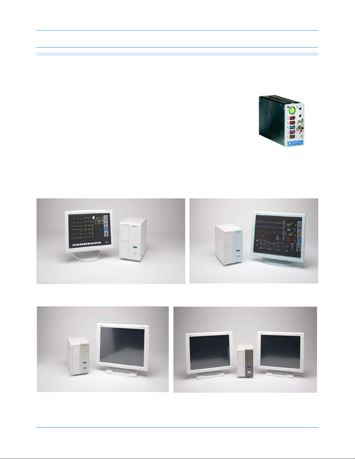
SL Command Module
SL2700 bedside monitor
(neonatal configuration)
SL2900 bedside monitor (and displays)
SL2800 bedside monitor (and display)
SL2700 bedside monitor (and display)
System Components
Spacelabs Healthcare monitoring products include:
• Bedside monitors
• Central monitors
• Parameter modules
• Module housings
• Printers
• Flexport
• Telemetry
®
system interfaces
Ultraview SL Operations Manual 1-4
Page 17
Introduction
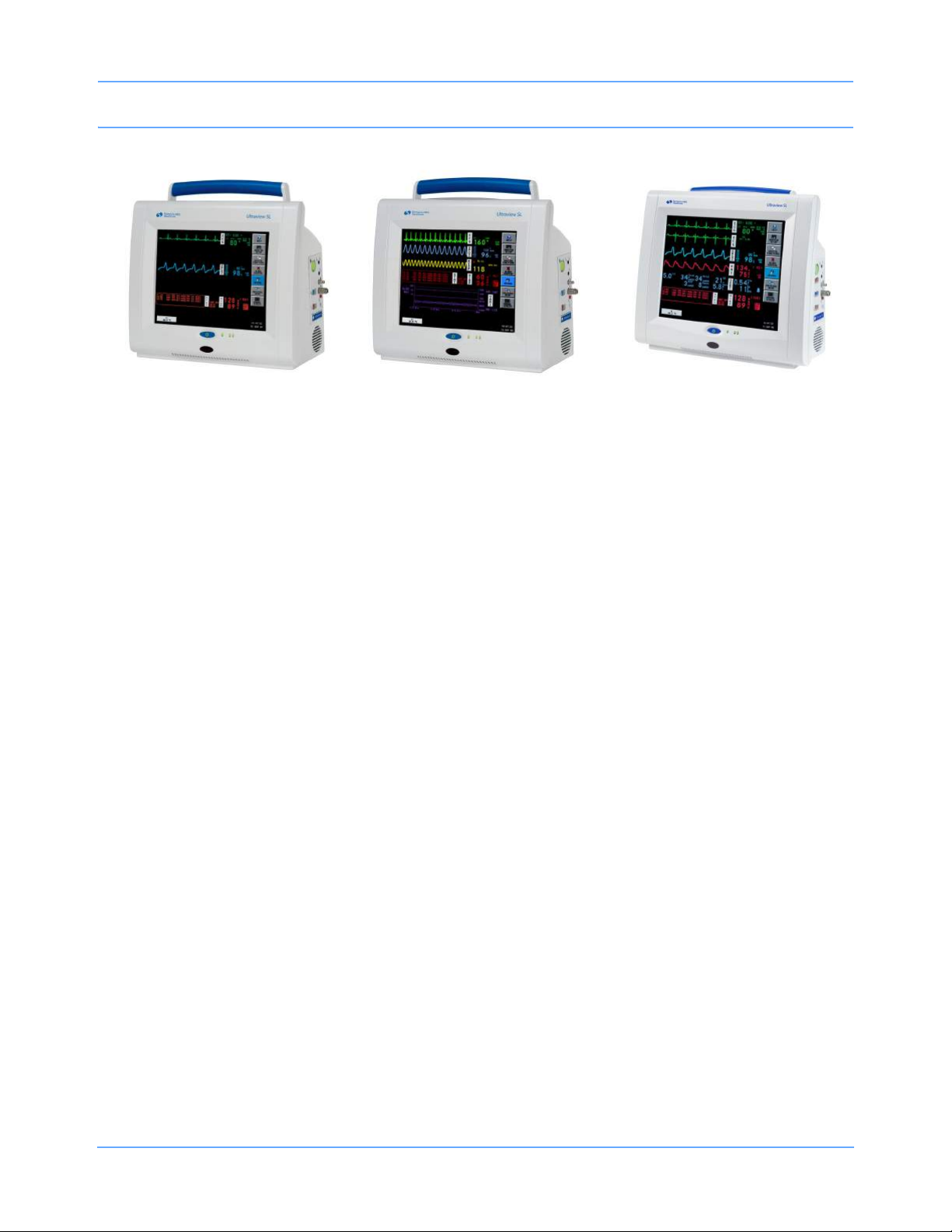
SL2400 bedside
monitor or portable monitor
SL2600 bedside monitor or
portable monitor
SL2200 bedside monitor or
portable monitor
Figure 1-2: Spacelabs Healthcare system components
SL2200 Monitor
The SL2200 is a lightweight, compact monitor with a 10.4-inch touchscreen display. It is designed for bedside
and portable use. The SL2200 includes an infrared receiver to support remote keypad operation. The monitor
supports one parameter module internally and supports networking. An optional printer and optional wireless
networking capabilities are available. Refer to the Ultraview SL2200 (91367) OperationsManual, P/N
070-1332-xx, for more information.
SL2400 Monitor
The SL2400 is a lightweight, compact monitor with a 10.4-inch touchscreen display. It is designed for bedside
and portable use. The SL2400 includes an alarm light and an infrared receiver to support remote keypad
operation. The monitor supports one parameter module internally and supports conventional networking. An
optional printer and optional wireless networking capabilities are available. The monitor is compatible with the
91493 Integrated Module Housing to support two additional parameter modules.
SL2600 Monitor
The SL2600 is a mid-range, compact monitor with a 12.1-inch touchscreen display. It is designed for bedside
and portable use. The SL2600 includes an alarm light and an infrared receiver to support remote keypad
operation. The monitor supports one parameter module internally and supports conventional networking. An
optional printer and optional wireless networking capabilities are available. The monitor is compatible with the
91493 Integrated Module Housing to support two additional parameter modules.
SL2700, SL2800, and SL2900 Monitors
The SL2700, SL2800, and SL2900 are bedside monitors that accommodate two single-high parameter
modules using external displays. Included with each monitor is a DC power supply that provides power for the
monitor and up to three Flexport interfaces. The SL2700 and SL2800 are single-display configurations; the
SL2900 is a dual-display configuration. Refer to Flexport System Interface on page 1-9 for information on
Flexport interfaces.
Ultraview SL Operations Manual 1-5
Page 18

Introduction
SL3800 and SL3900 Monitors
The SL3800 and SL3900 central monitors display patient-specific parameters, remote alarms, and alarm limits
based on the settings of the bedside monitor, as determined by the primary caregiver. The SL3800 is a
single-display configuration; the SL3900 is a dual-display configuration. Refer to Central Monitors on page 4-5
for detailed information on the capabilities of these monitors.
Parameter Modules
Parameter modules are used with a Spacelabs Healthcare monitor to monitor clinical parameters such as
electrocardiography (ECG), noninvasive blood pressure (NIBP), pulse oximetry (SpO
electroencephalography (EEG), Bispectral Index (BIS), and capnography. Each module is shipped with default
settings for alarms and various other operational settings, which can be adjusted to meet the needs of your
patients or comply with your hospital’s protocol.
),
2
Some parameter modules can also be used to transfer all of a patient’s data from one monitor to another
monitor. This is accomplished using the Data Shuttle
more information.
®
option. Refer to Data Shuttle Option on page 3-16 for
Installing Parameter Modules
Modules can be inserted directly into the monitor, as shown in Figure 1-3 on page 1-7, or into a module
housing. Refer to 90491 and 90499 Module Housings on page 1-7 and 91493 Integrated Module Housing on
page 1-8 for additional information.
To install a module:
• Ensure that the locking lever on the module is closed and that the module is oriented
correctly.
• Insert the module into any open slot in the monitor or module housing.
• Slide the module into the monitor or module housing until the front of the module is
flush with the front of the monitor. A light “click” indicates that the module is locked in
place.
If the front of the module is not flush with the front of the monitor or module
housing, DO NOT FORCE THE MODULE.
• Remove the module and clear the obstruction before trying to insert the module again.
• If there is no obstruction, check the orientation of the module, then repeat the
installation steps.
Ultraview SL Operations Manual 1-6
Page 19
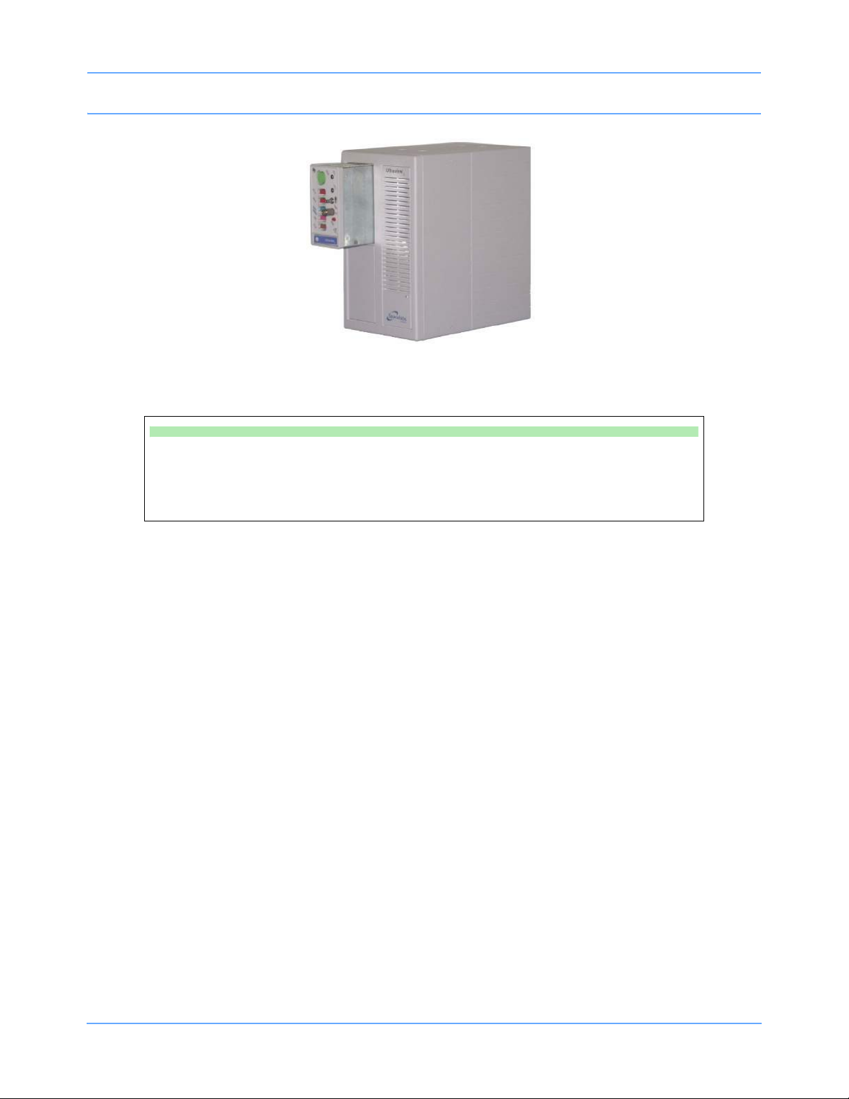
Introduction
Figure 1-3: Module insertion
To remove a module:
• Disconnect any cable(s) from the front of the module, if necessary.
• Push the left side of the locking lever.
• Hook your finger through the open locking lever, then pull the module out of the slot.
90491 and 90499 Module Housings
The 90491 and the 90499 module housings are lightweight, standalone units that expand the capabilities of a
Spacelabs Healthcare monitor, enabling the monitor to support additional parameter modules. Parameter
modules can be inserted into or removed from a module housing without disconnecting the power. Module
housing also provide flexible mounting and cabling options.
Both the 90491 and the 90499 module housings require a separate external power supply.
•The 90491 module housing accommodates four single-high modules or one double-high printer module
and two single-high modules.
•The 90499 module housing accommodates two single-high modules or one double-high printer module.
90491 and 90499 Module Housings — Power Failure
Warning:
• In case of a power failure, the module housing (90491 or 90499) provides +5 V of power to
maintain data integrity for up to three minutes.
• If the power is interrupted to the module housing but not to the monitor, the module remains
active and the following occurs:
- Waveforms go flat (as if the patient has no vital signs) or completely disappear.
- Parameter values default to the minimum limit or are displayed as question marks (???),
(except for noninvasive pressure, which displays the last value obtained before the power
failure).
Ultraview SL Operations Manual 1-7
Page 20
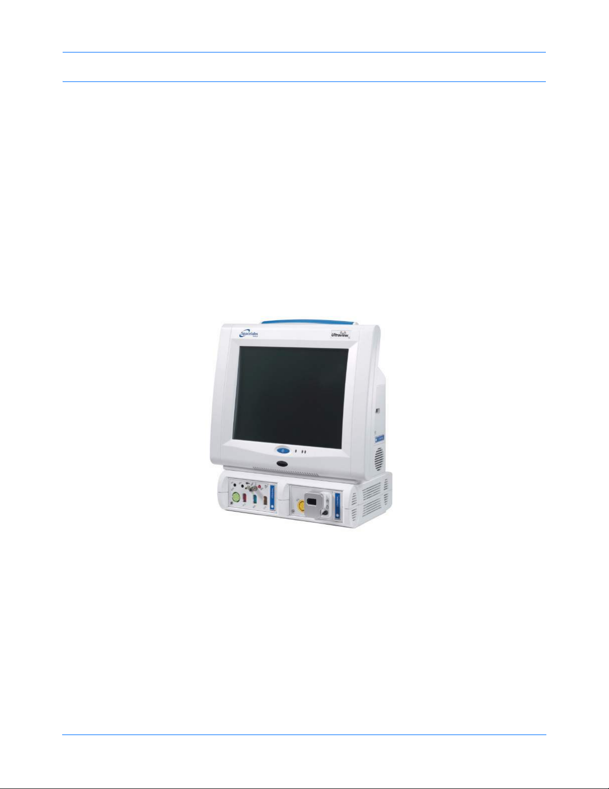
Introduction
- Alarms may sound for low limit violations or for conditions such as Asystole (ECG), Leads
Off (ECG), Loss of Signal (Respiration), or Adapter Disconnected (SpO
- Cardiac output displays Catheter Fault and Probe Fault.
• If any of the above conditions occur, check to determine whether or not AC power has been
interrupted to the module housing, and reestablish it, if necessary.
).
2
91493 Integrated Module Housing
The 91493 Integrated Module Housing expands the configurability of the SL2400/SL2600 compact monitors
from one to three modules by providing two additional module slots. The Integrated Module Housing directly
attaches to the base of the monitor.
Parameter modules can be inserted into or removed from a module housing without disconnecting the power.
The Integrated Module Housing is powered from the monitor, and does not use a separate power supply or
cables.
Figure 1-4: 91493 Integrated Module Housing shown with SL2600 monitor
Note:
• Modules inserted into the Integrated Module Housing must be aligned in the correct horizontal
orientation. Refer to Figure 1-4.
• The module label text should be readable when the module is inserted properly.
Ultraview SL Operations Manual 1-8
Page 21

Introduction
Printers
Patient information in the form of numerical data and waveforms can be printed using the 90449 printer
module, the 90469 system printer module, or an ICS printer. An integrated printer is also available in the
SL2400/SL2600 monitors.
The 90449 printer module is an external printer that prints one- or two-channel waveform recordings on 50-mm
heat-sensitive paper. It can store up to three waveforms and annotation values, and is only used as a bedside
printer.
The 90469 system printer module is an external printer that prints one-, two-, or four-channel waveform
recordings on 50-mm and 120-mm heat-sensitive paper. It can store up to 12 waveforms and annotation
values. Four-channel waveform recordings are only available when the four-channel paper tray is used. The
90469 system printer module may be used as a bedside printer or as a central printer.
The SL2400/SL2600 integrated printer is a two-channel printer that provides automatic and manual recordings
of parameter data on 50-mm roll paper. The printer prints recordings of parameters in alarm conditions,
requested waveforms, and non-waveform data.
Flexport System Interface
The Flexport system interfaces integrate data from compatible third-party peripheral devices (such as
ventilators, multigas analyzers, pulse oximeters, NIBP monitors, intravenous (IV) pumps, incubators, and
capnographs) into Spacelabs Healthcare monitors. Refer to External Flexport System Interface Connection on
page 3-23 for additional information.
Flexport interfaces provide current numeric data, alarm information, and selected waveforms. All the data
communicated to the Spacelabs Healthcare monitor is available at network locations, providing alarms and
centralized displays. Contact your Spacelabs Healthcare Sales Representative for additional information.
System Basics
Default Settings
Modules are shipped with factory defaults for alarms and other parameter settings (for example, NIBP reading
frequency), which can be adjusted to meet the needs of your patients. When events occur that might cause the
selected limits or values to return to the default settings, the monitor may display a CHECK SETUP key in the
ECG zone, combined with a low-priority alarm tone (refer to Setting Alarm Limits on page 7-7 for details on
alarm priorities). To cancel the message and the alarm, touch the CHECK SETUP key on the display. Refer to
Check Setup on page 3-6 for additional information.
Ultraview SL Operations Manual 1-9
Page 22
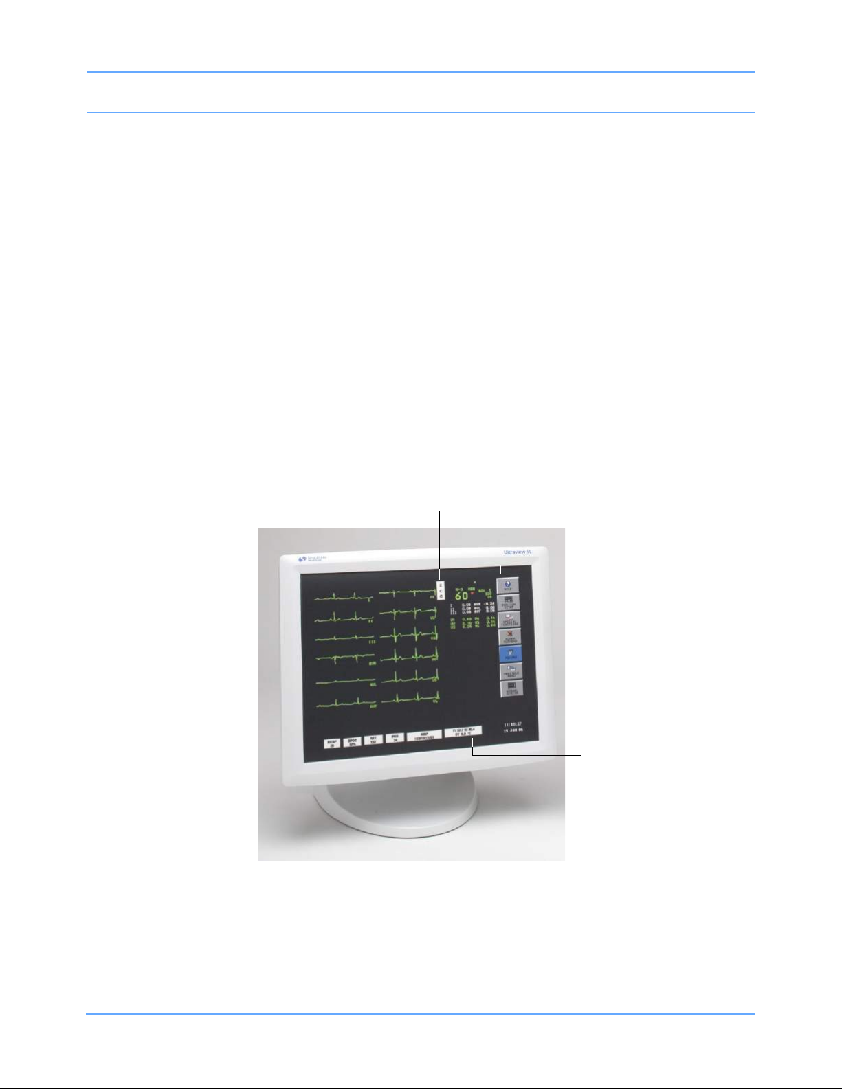
Introduction
Patient Preparation
To prepare a patient for monitoring, attach the lead wires and sensors to the patient and connect the sensors
cable to the module. Touch a parameter key, then touch menu keys as needed to set up monitoring for a
specific parameter. Refer to the parameter chapters for additional information on patient preparation.
Note:
Use only Spacelabs Healthcare parts and accessories with your Spacelabs Healthcare products. Other
parts and accessories may degrade performance or damage the components. Refer to the Spacelabs
Healthcare Supplies Products Catalog for the part numbers and descriptions of additional parts and
accessories.
Touchscreen Keys
Spacelabs Healthcare monitors use touchscreen keys to execute monitoring functions (refer to Figure 1-5).
These keys are:
Parameter keys
Monitor keys
Menu keys
Figure 1-5: Touchscreen keys
Ultraview SL Operations Manual 1-10
Page 23
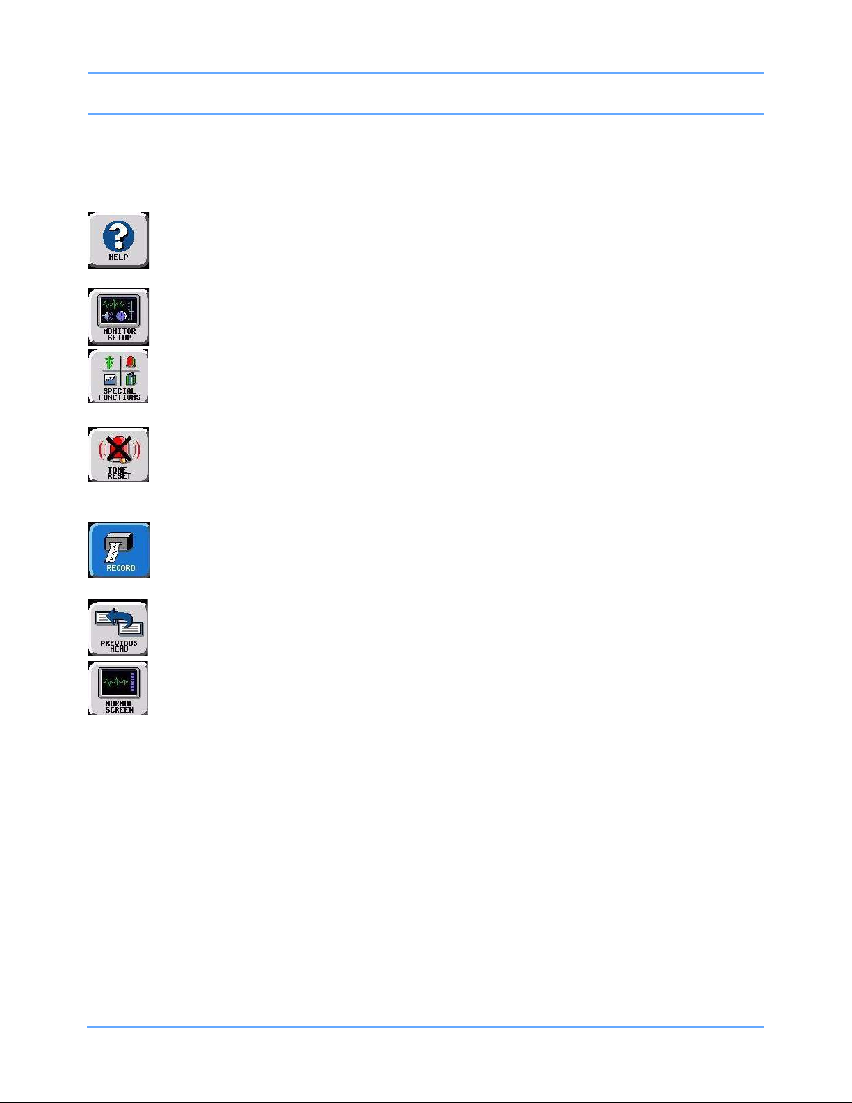
Introduction
Monitor Keys
Monitor keys are located in a vertical row along the right side of the monitor’s display. They are always visible
and perform specific functions regardless of the parameter being monitored.
HELP — Touch the HELP key and then the touchscreen key if you have questions about a key.
A description of that key’s function appears. Touching the HELP key twice displays system
information (model and software version) and configuration data.
MONITOR SETUP — Touch this key to remotely enter patient demographic data, modify the
display format, adjust brightness, adjust tones, and specify printing settings.
SPECIAL FUNCTIONS — Touch this key to remotely view other bedside monitors, to activate
automatic notification of remote alarms, to view trends, to view clinical and drug calculations, and to
use other optional network applications, such as WinDNA.
TONE RESET/ALARM SUSPEND — Touch this key once during an alarm condition to silence the
alarms for 45 seconds at that monitor (bedside or central). Touch the key again during the initial
45-second suspension to silence the alarms for three minutes at the bedside monitor only. Refer to
Alarms on page 7-5 for more details.
RECORD — Touch this key to print monitored data using a bedside printer, system printer, or
printer module. Touch this key and then touch a flashing parameter key to print parameter data.
Refer to Printing on page 9-5.
PREVIOUS MENU — Touch this key to move backward through prior menu levels one at a time.
From the Main Menu level, this key removes the menu or window from the display.
NORMAL SCREEN — Touch this key to close any active window and its menus and return the
monitor to its basic display.
Parameter Keys
Touching the parameter key to the right of the waveform zone displays menu keys at the bottom of the display
that are specific to that parameter.
Menu Keys
The menu keys appear along the bottom of the monitor’s display. They display controls for specific parameters
and the monitor keys.
Menu keys that are active appear in a contrasting color. Inactive keys appear dithered or in dim lettering. If you
touch an inactive menu key, an error tone sounds.
Ultraview SL Operations Manual 1-11
Page 24
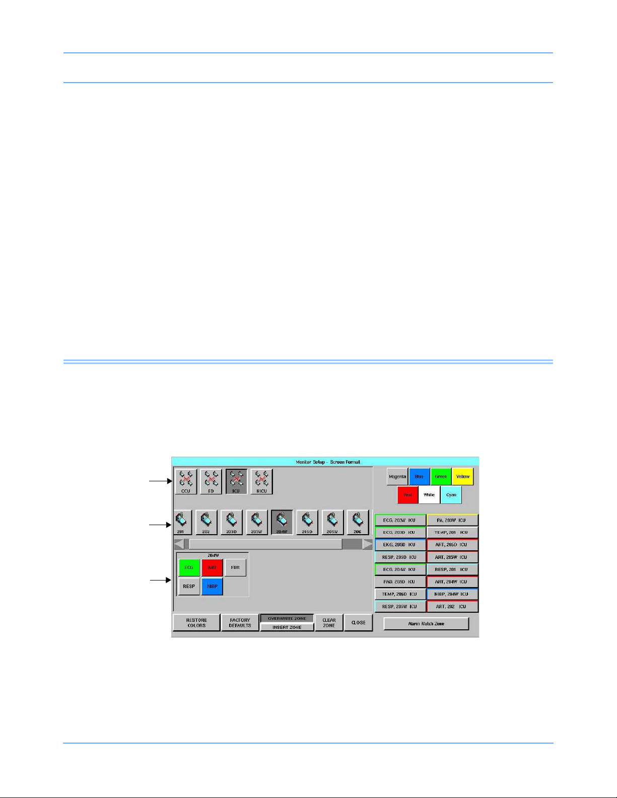
Introduction
Using a Keyboard and Mouse
Monitors support standard USB keyboards and mice as optional control devices.
An on-screen keyboard is provided for certain applications, such as Admit/Discharge, but you can also use an
external keyboard. Refer to Changing or Entering New Patient Data on page 8-3 for a description of the on-
screen keyboard.
If your system is equipped with a mouse, it can be used for selected functions in place of the keyboard or the
touchscreen. To use the mouse, position the cursor on a key and click the left mouse button to activate
that key.
Remote Control Keypad (90360)
The optional 90360 remote control keypad is a cordless, hand-held transmitter powered by an internal battery.
It transmits instructions needed to operate a monitor via infrared signals to the monitor’s receiver. Using the
remote control keypad, you can remotely suspend or adjust alarms, access trends, adjust waveform size, and
print. The zoom function enlarges menu keys on the monitor, making them easy to read from across the room.
The maximum operating range is 6 meters (20 feet) at an angle of up to 45 degrees on either side of the
receiver. A single 90360 can be used to control several monitors if each is equipped with an infrared receiver.
Refer to Remote Keypad on page 29-3 for additional information.
Network Basics
Networking enables you to communicate between beds in a single care unit or to review information from
another care unit by specifying the unit as well as the bed. Each care unit is designated as a subnet on your
networked system. This identification appears on the subnet keys in the bed selection menus.
Figure 1-6: Screen Format menu, split-display central monitor
Subnet keys
Bed keys
Parameter keys
Ultraview SL Operations Manual 1-12
Page 25
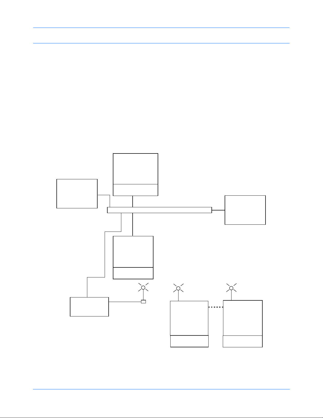
Introduction
91387
Bedside #n
8 display zones
color
91370
Bedside #n
4 or 6 display
zones
Clinical
Information
System
91369-X
Bedside #n
4 display zones
91387
Central #n
up to 16 display
zones
91369-X
Bedside #n
4 display zones
*Access Point
Module
Module
Module Module
Ethernet network
*Not supplied by Spacelabs.
When you view clinical parameter information for a particular bed from another bedside monitor, or from a
central monitor, you can control those parameters just as if you were at that remote bedside.
Some of the available features are:
• Standard networking, which allows the remote viewing of parameter data from bedside to bedside, and
from bedside to central monitor (refer to Viewing Remote Parameters on page 1-14).
• Advanced networking, which allows remote access and interaction with clinical and drug calculations and
tabular and graphic trends(refer to Reviewing Remote Trends on page 1-16).
• Full Bed Review, which allows remote viewing of the entire bedside monitor information (refer to Full Bed
Review on page 1-17).
The Spacelabs Healthcare network is configured according to your hospital’s specifications. Typically,
hospitals designate a system administrator for this task.
Figure 1-7 illustrates a possible Spacelabs Healthcare network configuration.
Ultraview SL Operations Manual 1-13
Figure 1-7: Example of a network configuration
Page 26

Introduction
Alarm Watch
With the network Alarm Watch feature, you can be notified at a local bedside or the central monitor of all
alarms from a remote bed (refer to Alarm Watch on page 7-12 for additional information).
Viewing Remote Parameters
The Remote View feature enables you to view data from any bedside monitor at any other bedside or the
central monitor. Remote views of waveforms and numerics are nearly identical in appearance and function to
those of the parameter at the originating monitor. Each patient’s data appears in a zone that is separated from
other zones by a dividing line. Menu keys, alarms, and recordings are also accessible. Arrhythmia and ST
segment data can be viewed from remote monitors if optional arrhythmia and ST segment analysis software is
part of your system. Parameters from bedside monitors can be remotely viewed by up to 16 other monitors.
To view remote parameters:
Bedside Monitor Central Monitor
• Touch SPECIAL FUNCTIONS.
• Touch REMOTE VIEW.
• Select a bed, or select a subnet and then
select a bed.
• Select a parameter key.
• Touch MONITOR SETUP.
• Touch SCREEN FORMAT.
• Select the destination waveform zone.
• Select a parameter and a color.
Ultraview SL Operations Manual 1-14
Page 27
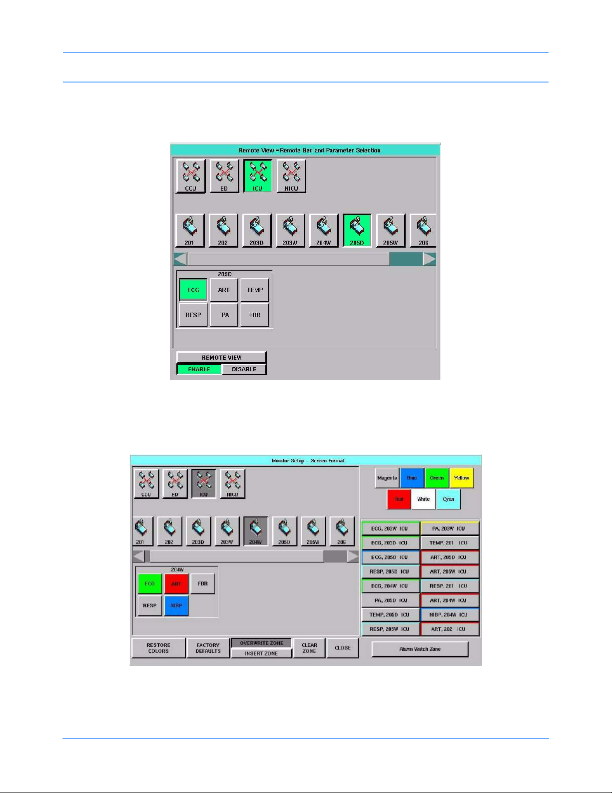
Introduction
Remotely viewed parameters occupy the lowest zone on the bedside monitor display. When a bedside monitor
is set up to remotely view a parameter from another bedside, a one-second advisory tone sounds at the onset
of an alarm condition (if the remote alarm tone is enabled).
Figure 1-8: Bedside monitor, Remote View bed and parameter selection
On the central monitor, a specific zone is assigned to each remote parameter. Central monitors sound alarm
tones in the same manner as bedside monitors.
Figure 1-9: Central monitor, Screen Format bed and parameter selection
Ultraview SL Operations Manual 1-15
Page 28

Introduction
The central monitor also features an optional communications interruption feature. Keys will appear in the
waveform zone of the interrupted channel to permit disabling of the alarm tone associated with the interruption,
and to remove the zone from the display. Refer to Data Communications Watch on page 4-8 for more
information.
Reviewing Remote Trends
Vital signs trending provides minute-by-minute logging of parameter data for review and documentation in the
patient record. Retrospective vital sign review through either graphic or tabular trends provides minute-byminute access to data from any monitor on the network. You can select the format and interval for trending.
Refer to Trends on page 28-3.
To display a trend from a remote monitor:
• Touch SPECIAL FUNCTIONS.
• Touch REMOTE TRENDS/CALCS.
• Select a bed, or select a subnet and then select a bed.
• Touch GRAPHIC TRENDS or TABULAR TRENDS.
Ultraview SL Operations Manual 1-16
Page 29
Introduction
Full Bed Review
The optional Full Bed Review (FBR) feature (available with the SL2600/SL2700/SL2800/SL2900/SL3800/
SL3900 monitors only) enables you to simultaneously view multiple parameters from a remote monitor at your
bedside or central monitor. If no menus appear when a bedside or central monitor is displaying another
monitor’s data, an FBR key appears in the lower left corner. Selecting this key activates the FBR feature.
The monitor where FBR is enabled displays, within its capabilities, all available parameters from the remote
monitor. If more parameters are available from the remote bedside than FBR can display, keys for these
additional parameters are displayed as numeric keys along the bottom of the display. Selecting any of these
numeric keys causes the selected parameter to replace the lowest parameter on the display.
To activate Full Bed Review (FBR) when a remote parameter is displayed:
Bedside Monitor Central Monitor
• Touch NORMAL SCREEN to
display all parameters.
•Touch FBR.
To activate Full Bed Review (FBR) when a remote parameter is not displayed:
Bedside Monitor Central Monitor
• Select a bed, or select a subnet and then
select a bed.
• Touch the FBR key displayed after the last
parameter key.
•-OR-
• To activate FBR as described above,
select a parameter key.
To deactivate Full Bed Review (FBR):
• Touch NORMAL SCREEN.
• Touch NORMAL SCREEN to display all
parameters.
•Touch FBR.
• Touch the flashing parameter key for the
remote bed.
• Select a waveform zone where you want
to assign the parameter.
Ultraview SL Operations Manual 1-17
Page 30
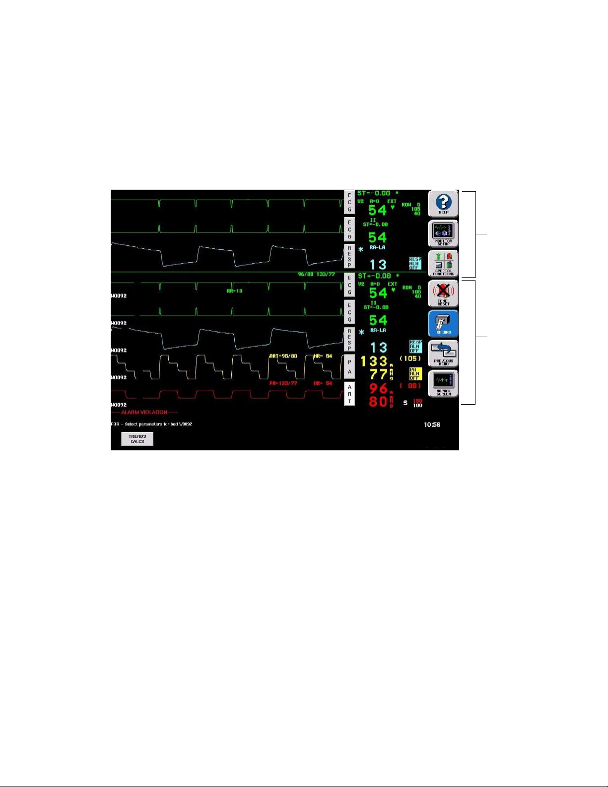
The parameter keys displayed by the FBR function are interactive. To access the controls for a parameter,
1 Jan 06
touch that parameter’s key. Remote review of trended or calculated data for the selected monitor is available
by touching the REMOTE TRENDS/CALCS key in the Special Functions menu.
Note:
Full Bed Review displays a single ECG lead if the remote bedside is configured to display ECG data using
the full-view format or split-view format.
Local bedside view
Remote bedside view
Figure 1-10: Full Bed Review
Page 31

Glossary of Terms
This summary provides definitions of terms related to the Ultraview SL™ products.
12-Lead diagnostics
(page 13-3)
90449 bedside printer module
(page 9-9)
90469 system printer module
(page 9-11)
90491 module housing
(page 1-7)
90499 module housing
(page 1-7)
90838 PrintMaster
(page 9-14)
91517 Capnography module
(page 23-5)
91493 Integrated
Module Housing
(page 1-8)
Conventional ECG signatures that accurately represent both the detailed
waveforms in each cardiac cycle and their beat-to-beat variability.
A two-channel printer that provides automatic and manual recordings of
parameter data on 50 mm Z-fold paper.
A two- or four-channel printer that provides automatic and manual
recordings of parameter data on 50 mm or 120 mm Z-fold paper.
Accommodates four single-high modules or one double-height printer
module and two single height modules.
Accommodates two single-high modules or one double-height printer
module.
A four-channel, network printer that provides automatic and manual
recordings of parameter data on 8.5-inch × 11-inch or A4-size paper.
A mainstream and sidestream gas analyzer designed to measure the
concentration of carbon dioxide in a gas mixture. Aids in determining the
patient’s ventilatory, circulatory, and metabolic status.
The 91493 Integrated Module Housing (IMH) expands the configurability of
the SL2400/SL2600 portable monitors from one to three modules by
providing two additional module slots. For bedside or transport use, the
IMH attaches directly to the base of the portable monitors and does not
require a separate power supply or cables.
Admit/discharge
(page 8-3)
Advanced networking
(page 1-16)
Alarm attributes
Alarm Limit Review
(page 7-16)
Alarm recording
(page 7-15)
ALARM SUSPEND key
(page 7-11)
Ultraview SL Operations Manual 2-1
Enter new patient data, change data for an existing patient, and delete
patient data if the patient is discharged.
Access and interact with clinical and drug calculations and tabular and
graphic trends on remote monitors.
Alarm attributes (such as tone type, alarm recording, and alarm watch)
can be independently configured for all parameters via the Module
Configuration Manager. For more information, refer to the Ultraview SL
Module Configuration Manager System Administration Guide
(P/N 070-1245-xx).
Provides a snapshot view of bedside alarm limits for all active parameters
(only available with specific Ultraview SL modules).
A strip recording initiated upon an alarm.
(Also refer to TONE RESET.) Bedside monitor feature that suspends all
alarms and alarm recordings for three minutes.
Page 32

Glossary of Terms
Alarm Tone Manager
(page 7-14)
Alarm Watch
(page 7-12)
Arrhythmia
(page 11-3)
Arrhythmia trends
(page 11-12)
Arrhythmia review
(page 11-9)
ART
(page 20-3)
A feature used by a system administrator to prevent alarm tones from
being permanently disabled.
Notifies you of alarms from a remote bed.
Referring to the monitor’s ECG detection and classification capabilities.
Detailed trend presentation of Multiview
™
II arrhythmia data.
The event and class review feature associated with the Multiview II
arrhythmia algorithm.
Arterial Pressure. The first factory-default invasive pressure channel label.
Battery backup A feature that preserves patient data during brief losses of mains power.
Bispectral Index (BIS)
(page 26-3)
Calculations
(page 27-5)
A mathematical value between 0 and 100 derived from the frequency,
power, and phase throughout the entire frequency range of the EEG.
Hemodynamic, respiration, oxygenation, and renal calculations that use
input values entered manually, or collected automatically by the system, to
produce a set of output values.
Capnography
(page 23-5)
Cardiac output
(page 21-3)
Central Alarm Watch Manager
(page 7-14)
A highly accurate method of measuring respiratory gas values.
Evaluates the patient's fluid status and the heart’s pumping ability.
A feature used by a system administrator to allow alarm notification from a
remote bed.
Clinical calculations Refer to Calculations.
Clock (system)
(page 3-12)
A clock can be continually displayed in the lower right corner of the display.
Multiparameter module consisting of eight different parameter
Command module
(page 1-5)
configurations of multi-lead ECG, noninvasive blood pressure (adult and
neonatal), invasive pressure, pulse oximetry, cardiac output, and
temperature combined into a single module.
CPP
(page 20-7)
Data Communications Watch
(page 4-8)
Cerebral perfusion pressure. An invasive pressure label.
The central monitor notifies you when its communication link with a
bedside monitor is interrupted.
Ultraview SL Operations Manual 2-2
Page 33

Glossary of Terms
Data Shuttle
(page 3-16)
Transfers up to 24 hours of trend and episodic data, plus patient
demographic data (e.g., age, gender, name, and BSA), from one monitor to
another.
Modules are shipped with factory-default settings for alarms and other
Default settings
parameter settings. User-defined settings can be configured using the
Module Configuration Manager.
Density Spectral Array (DSA) An EEG display format.
Diagnostic messages
(page 34-1)
Digital telemetry
(page 18-3)
Directory of keys
A chapter in this manual listing messages that may appear on the display.
Provides continuous monitoring of electrocardiographic signals in order to
detect abnormal cardiac rhythms, including asystole, ventricular fibrillation,
and ventricular tachycardia.
Diagrams of touchscreen keys and menus at the beginning of each
chapter.
DNA
(Dynamic Network Access)
Enables you to view and control a remote application.
(page 3-7)
Drug Dosage calculations
(page 27-19)
Enables you to determine infusion rates for drugs based on drug
concentration, desired dose, patient weight, and patient type (adult or
neonate).
Dynamic Network Access Refer to DNA.
Electrocardiograph (ECG)
(page 10-5)
Electroencephalograph (EEG)
Enhanced vital signs
Event
(page 15-6)
Event marks
A method of continuously monitoring electrocardiographic signals.
A method of acquiring, processing, and displaying two- or four-channel
EEG data and one channel of EMG (electromyogram) data.
Displays SpO
, respiration rate, and noninvasive pressure in the ECG
2
zone on central or remote bedside monitors.
A change in a patient’s condition based on multiple variables.
Indications at the top of any SvO
when an event occurs.
FBR Refer to frequency band ratio.
FBR Refer to Full Bed Review.
Flexport system interface
(page 1-9)
Integrates data from compatible peripheral devices (such as ventilators,
multigas analyzers, incubators, and capnographs) into Spacelabs
Healthcare monitors.
or EEG trend graph to note the point
2
Ultraview SL Operations Manual 2-3
Page 34

Glossary of Terms
Frequency band ratio (FBR) A measurement of the ratio of total power in two EEG frequency bands.
Full Bed Review (FBR)
(page 1-17)
Graphic trends
(page 28-4)
Enables you to simultaneously view multiple parameters from a remote
monitor.
Refer to Trends.
Touch the HELP monitor key and then a touchscreen key to display a
HELP key
(page 1-11)
description of that key’s function. Touching the HELP key twice displays a
window containing system information (model and software version) and
configuration data.
ICD
(page 31-6)
Implantable Cardiac Defibrillator.
ICS Intesys
Indication for Use
(page 31-1)
The devices documented herein are indicated for use by health care
professionals whenever there is a need for monitoring of the physiological
parameters of patients.
The devices documented herein are intended to be used for monitoring of
multiple physiological parameters for patients of any age ranging from
neonates through adults. In addition to monitoring physiological
parameters, these devices also support recording and alarming for those
Intended Use
parameters.
(page 31-1)
The devices documented herein are not therapeutic devices. The devices
documented herein are to be used by trained health care professionals in
health care facilities. ST segment monitoring is restricted to adult patients
only. The devices documented herein are not intended for home use.
Clinical Suite.
Invasive pressure
(page 20-3)
Labels
Local Calcs
(page 27-5)
Local Trends
(page 28-3)
Masimo SET
(page 17-7)
Mainstream and sidestream
capnography
Ultraview SL Operations Manual 2-4
Uses an intravascular strain-gauge transducer to measure systolic (S),
diastolic (D), and mean (M) arterial blood pressures.
The name that appears on a parameter key, such as a pressure key label
(ART, PA, PRS, CVP, etc.).
Refer to Calculations and Drug Dosage Calculations.
Refer to Trends.
A pulse oximetry technology developed by Masimo.
Highly accurate methods of measuring respiratory gas values.
Page 35

Glossary of Terms
Module Configuration
Manager (MCM)
Module housing
(page 1-6)
MONITOR SETUP key
(page 1-11)
Montage
Multigas analyzer
(page 24-1) and (page 25-1)
Multiparameter telemetry
Multiview I and II
(page 11-3)
Networking
(page 1-14)
Define and store user-configurable options within your module. For more
information, refer to the Ultraview SL Module Configuration Manager
System Administration Guide (P/N 070-1245-xx).
A lightweight, standalone unit that allows the monitor to support additional
parameter modules.
Displays a menu for entering patient demographic data, modifying the
display format, adjusting tones, and specifying printing settings.
Used in BIS monitoring to view or enter electrode lead placement, enable
EMG, and initiate continuous impedance testing.
Monitors gas concentrations and alerts clinical personnel when the
concentration of anesthetic agents, oxygen, carbon dioxide, or nitrous
oxide falls outside of defined limits.
Digital telemetry product with options to acquire SpO
and NIBP data, as
2
well as ECG data.
Enhanced (Multiview I) and expanded (Multiview II) arrhythmia detection
and alarms. Multiview II also offers storage and review capabilities.
View and interact with parameter data from bedside to bedside, and from
bedside to central monitor.
Noninvasive Blood Pressure
(NIBP)
(page 16-1)
NORMAL SCREEN key
(page 1-11)
NIBP uses oscillometric monitoring to measure systolic (S), diastolic (D),
and mean (M) arterial blood pressures.
Returns the monitor to its basic display.
Nurse Alert An optional external monitor configuration accessory.
OCR Refer to oxycardiorespirogram.
OxiMax
(page 17-14)
Oxycardiorespirogram
(page 14-3)
Pacemaker
(page 10-15)
Parameter priority and color
(page 3-8)
Patient Data Logger (PDL)
(page 30-3)
A pulse oximetry technology developed by Nellcor.
A graph displaying heart rate, SpO
, and respiratory rates.
2
A cardiac pacemaker.
Allows control of parameter position and color on the display.
An option that automatically sends patient vital signs from the monitor to an
external device, such as a printer or a terminal.
Ultraview SL Operations Manual 2-5
Page 36

Glossary of Terms
Patient identification string
A text string used to identify the patient associated with remotely viewed
data.
Physiologic calculations Refer to Calculations.
Plethysmograph
(page 17-11)
Power failure
(page 1-7)
Associated with SpO
.
2
Loss of mains power. Refer to Battery backup on page 2-2.
Pressure Refer to Invasive Pressure.
PREVIOUS MENU key
(page 1-11)
Printer module
(page 9-5)
Printing priorities
(page 9-7)
Privileged access
(page 3-15)
Move backwards through prior menu levels one at a time.
A module that prints recordings of parameters in alarm conditions,
requested waveforms, and non-waveform data.
Recording requests are printed in a priority order.
Additional features available to any user with an appropriate password.
Product specifications
(page 31-1)
Pulse oximetry (SpO
)
2
(page 17-5)
Pulse pressure variation
(page 20-12)
QRS tone
(page 3-15 and page 10-21)
Quicknet
™
Quickstarts
(page 1-3)
Real-time ST trends
(page 12-13)
A chapter in this manual that provides specifications for Spacelabs
Healthcare products.
Allows continuous noninvasive monitoring of a patient's hemoglobin
oxygen saturation.
Pulse pressure variation (PPV) can help clinicians to evaluate a patient's
fluid volume status through the characterization of changes in the invasive
pressure waveform in relation to respiration.
A tone that occurs each time a QRS complex is detected.
Hospitals may choose to install additional network connections in patient
rooms or hallways that are not permanently connected to a Spacelabs
Healthcare monitor. These additional connections give hospitals greater
flexibility in using their floating monitors during periods of high patient
census, etc.
Quickstarts explain how to access and use features of the Spacelabs
Healthcare monitors.
An ECG feature that displays 15 or 30 minutes of ST trend data at all
times.
Receivers
(page 18-11)
Ultraview SL Operations Manual 2-6
Used with a patient-worn telemetry transmitter to provide continuous
monitoring of electrocardiographic signals.
Page 37

Glossary of Terms
RECORD key
(page 1-11)
Recording destination
(page 9-18)
Remote calcs
(page 27-5)
Remote keypad
(page 29-3)
Touching this key prints monitored and parameter data using a bedside
printer, system printer, or printer module.
Enables you to direct alarm recordings to a bedside printer, a network
printer, or both. Other recordings can be directed to a bedside printer or to
a network printer, but not to both.
Display of calculated data from a remote monitor on the network.
A cordless, hand-held transmitter that sends instructions, via infrared
signals, to the monitor’s receiver. Provides all the functions needed to
operate the monitor remotely.
Remote monitor Any other monitor on the network.
Remote trends
(page 28-3)
Remote View
(page 1-14)
Reports
(page 13-3)
Display of vital sign trends from a remote monitor on the network.
View and control parameter data from a remote monitor on the network.
12-lead ECG reports.
Respiration
(page 14-3)
Sensorwatch
®
(page 17-12)
SL2400 monitor
(page 3-5)
SL2600 monitor
(page 3-5)
SL2700/SL2800 monitors
(page 3-5)
Changes in thoracic impedance during patient inspiration and expiration
provided through the ECG cable.
A graphical presentation of the amplitude of the signal received from the
sensor that can be used to determine the best sensor site and application.
The SL2400 is a lightweight, compact monitor with a 10.4-inch
touchscreen display. It is designed for bedside and portable use. The
SL2400 includes an alarm light and an infrared receiver to support remote
keypad operation. The monitor supports one parameter module internally
and supports conventional networking. An optional printer and optional
wireless networking capabilities are available. The monitor is compatible
with the 91493 Integrated Module Housing to support two additional
parameter modules.
The SL2600 is a mid-range, compact monitor with a 12.1-inch touchscreen
display. It is designed for bedside and portable use. The SL2600 includes
an alarm light and an infrared receiver to support remote keypad operation.
The monitor supports one parameter module internally and supports
conventional networking. An optional printer and optional wireless
networking capabilities are available. The monitor is compatible with the
91493 Integrated Module Housing to support two additional parameter
modules.
Bedside monitors that use external displays and accommodate two
single-high parameter modules.
Ultraview SL Operations Manual 2-7
Page 38

Glossary of Terms
SL3800 monitor
(page 4-5)
SPECIAL FUNCTIONS key
(page 1-11)
SpO
tone
2
(pages 3-15, 10-21, and 17-19)
ST analysis
(page 12-3)
A central monitor that displays patient-specific parameters, remote alarms,
and alarm limits based on the settings of the bedside monitor, as
determined by the primary caregiver.
Displays a menu for performing Remote View and Alarm Watch, viewing
trends and clinical and drug calculations, and using other optional network
applications, such as WinDNA
A tone that occurs each time an SpO
®
.
pulse is detected.
2
Monitors changes to the ST segment level.
ST segment review A review feature associated with the ST segment analysis feature.
Standard networking
(page 1-14)
View and interact with parameter data from bedside to bedside monitor,
and from bedside to central monitor.
Status messages Indicate a problem or condition that may affect accurate monitoring values.
Symbols
(page A-1)
Tabular trends
(page 28-5)
A chapter in this manual that provides graphical illustrations of the symbols
used on Spacelabs Healthcare products.
A table displaying up to 22 rows and 7 columns of continuous or episodic
parameter data.
Tel eme t r y Refer to Digital Telemetry.
Temperature
(page 19-3)
Titration tables
(page 27-25)
TONE RESET key
(page 7-11)
Transmitters
(page 18-3)
Trends
(page 28-3)
Troubleshooting information
Refer to Temperature.
The Drug Dosage calculation feature includes titration tables that appear
for each drug record to calculate flow rate and dose.
Silences the alarm tone for 45 seconds at that monitor.
Small, battery-powered devices that monitor ECG activity and, optionally,
SpO
/NIBP data, and transmit this information to the digital telemetry
2
receiver module.
Numeric data collected for a patient over a 24-hour period that is displayed
in either a graphical or tabular format.
A section located at the end of most chapters that suggests solutions to
common problems.
An optional feature in some 91496 modules. The Varitrend graph provides
Varitrend
(page 15-3)
®
4
a real-time, continuous display of heart rate, respiration rate or
compressed respiration waveform, SpO
EtCO
, as well as TcpCO2, and TcpO2.
2
(pre- and post-ductal sites),
2
Ultraview SL Operations Manual 2-8
Page 39

Glossary of Terms
VCRR
View, control, review, and record data displayed by Spacelabs Healthcare
monitors.
Venous oxygen
saturation (SvO
)
2
A status indicator of the oxygen transport system in critically ill patients.
(page 22-3)
Venous stasis
(page 16-12)
Vitals report
(page 9-22)
Uses the NIBP cuff as the tourniquet for venous cannulation.
A manual report on 50 mm roll paper of selected parameter data that prints
on the SL2400/SL2600 compact monitor printer.
Vital signs trending Refer to Trends.
WFI
(page 17-11)
SpO
waveform index.
2
Ultraview SL Operations Manual 2-9
Page 40

Page 41

Bedside Monitors
SL2400/SL2600
monitor
only
Directory of Keys
Refer to
Introduction
Refer to
Alarms
Refer to
Printing
Refer to Introduction
SPECIAL FUNCTIONS
REMOTE
VIEW
Refer to
Introduction
ALARM
WATCH
RV/AW
OFF
Refer to Alarms Refer to Trends and Calculations Refer to
ALARM LIMIT
REVIEW
LOCAL TRENDS/
CALCS
REMOTE
TRENDS/CALCS
MONITOR SETUP
TONES
Refer to
Alarms
ADMIT/
DISCHARGE
Refer to
Admit/Discharge
MONITOR
CONFIG.
RECORDER
CONFIG.
Refer to
Printing
PRIVILEGED
ACCESS
Refer to
page 3-2 and
page 3-3
MONITOR CONFIGURATION
ENERGY SAVING MODE SCREEN BRIGHTNESS
ON OFF OR NORMAL DIM ON OFF ON OFF
DC Power AC Power
MINOR
GRATICULE
PARAMETER
CONFIG
CLOCK ALARM LIGHT
DATA
LOGGER
page 3-7
SCREEN SAVER
DNA
Refer to
page 5-1
AC TIVATE
MINOR GRATICULE - 2 divisions
MINOR GRAT
ON OFF
Ultraview SL Operations Manual 3-1
Page 42

Privileged Access
SL2400/SL2600
monitor
only
Bedside Monitors
Refer to
Introduction
MONITOR SETUP
PRIVILEGED
ACCESS
Enter clinical
password
and touch
ENTER
CLINICAL LEVEL - Select Parameter
TIME/
DATE
PRESELECTED
RECORDINGS
Refer to
Printing
UNITS OF
MEASURE
USER ACCESS - Enable user access to functions
PATIENT TYPE PARAMETER CONFIG RECORDING DURATION SUBNET ACCESS
ON OFF ON OFF ON OFF ON OFF
Refer to
Alarms
Refer to
Printing
USER
ACCESS
Refer to Introduction
ALARM
SETUP
Refer to
page 3-3
ALARM WATCH
SETUP
Refer to
page 3-3
MORE
Refer to
page 3-3
DEFAULT ENG. SAV MODE
ON OFF
Restart monitor after selecting units of measurement
mmHg inches lb
kPa cm kg
MONITOR SETUP - Time/Date 10:06 AM/PM
TIME
DATE PM
Ultraview SL Operations Manual 3-2
24
HOURS
AM
HOURS MINUTES
ENTER
Page 43
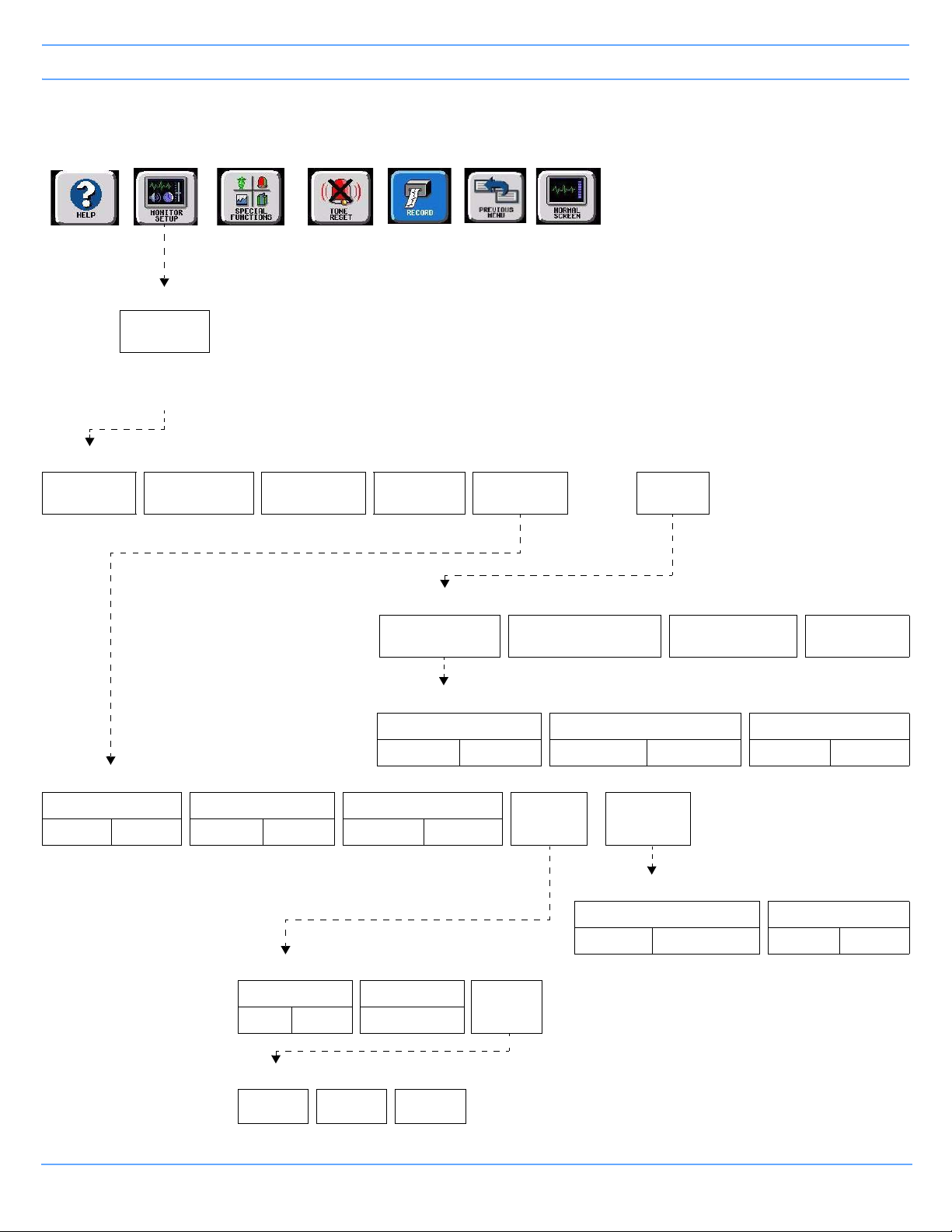
Privileged Access (continued)
Bedside Monitors
Refer to
Introduction
MONITOR SETUP
PRIVILEGED
ACCESS
Enter clinical
password
and touch
ENTER
CLINICAL LEVEL - Select Parameter
TIME/
DATE
Refer to
page 3-2
PRESELECTED
RECORDINGS
Refer to Printing Refer to
UNITS OF
MEASURE
page 3-2
Refer to
Alarms
Refer to
Printing
USER
ACCESS
Refer to
page 3-2
Refer to Introduction
ALARM
SETUP
CLINICAL LEVEL - Select Parameter
ALARM WATCH
SETUP
REMOTE KEYPAD
STATION ADDRESS
MORE
CHANGE CLINICAL
PAS SWOR D
RESET
MONITOR
ALARM WATCH SETUP - Select parameter to change
ROTATE ALARM WATCH ALARM WATCH ROTATION ROTATION TIME
ON OFF PRIORITY SIMPLE 15 S 30 S
ALARM SETUP - Select parameter
REMOTE ACCESS ALARM SUSPEND TREND SUSPEND
ON OFF ON OFF ON OFF
ALARM RELAY SETUP - Select parameter
RELAY TIMEOUT FLASHING
0 SEC 10 SEC STEADY ON
ALARM LEVEL - Select minimum alarm priority level to trigger relay activation
HIGH MEDIUM LOW
ALARM
LEVEL
ALARM
RELAY
MORE
ALARM SETUP - Select parameter
QRS/SPO2 TONE ENABLE ALARM WATCH TONE
ALWAYS DURING ALARM SINGLE TRIPLE
Ultraview SL Operations Manual 3-3
Page 44

Page 45

Bedside Monitors
Contents
Overview. . . . . . . . . . . . . . . . . . . . . . . . . . . . . . . . . . . . . . . . . . . . . . . . . . . . . . . . . . . . . . . . . . . . . . . . . . . . . 5
Display Detail . . . . . . . . . . . . . . . . . . . . . . . . . . . . . . . . . . . . . . . . . . . . . . . . . . . . . . . . . . . . . . . . . . . . . . . . . 7
Identifying Special Applications . . . . . . . . . . . . . . . . . . . . . . . . . . . . . . . . . . . . . . . . . . . . . . . . . . . . . . . . . . . 7
Monitor Configuration Features . . . . . . . . . . . . . . . . . . . . . . . . . . . . . . . . . . . . . . . . . . . . . . . . . . . . . . . . . . . 8
Wireless Networking (SL2400/SL2600 Only) . . . . . . . . . . . . . . . . . . . . . . . . . . . . . . . . . . . . . . . . . . . . . . . . 14
Privileged Access Menus . . . . . . . . . . . . . . . . . . . . . . . . . . . . . . . . . . . . . . . . . . . . . . . . . . . . . . . . . . . . . . . 15
Data Shuttle Option . . . . . . . . . . . . . . . . . . . . . . . . . . . . . . . . . . . . . . . . . . . . . . . . . . . . . . . . . . . . . . . . . . . 16
Power and Battery Status (SL2400/SL2600 Only) . . . . . . . . . . . . . . . . . . . . . . . . . . . . . . . . . . . . . . . . . . . . 19
SL2400/SL2600 Monitor Connections . . . . . . . . . . . . . . . . . . . . . . . . . . . . . . . . . . . . . . . . . . . . . . . . . . . . . 21
Bedside Monitor Troubleshooting Guide . . . . . . . . . . . . . . . . . . . . . . . . . . . . . . . . . . . . . . . . . . . . . . . . . . . 24
Overview
Parameter modules that are inserted into the monitor itself or into a module housing acquire patient data to
display as waveforms and numerics.
The bedside monitor can (optionally) display up to eight parameter zones. If more than eight zones are used,
numeric keys appear at the bottom of the display for the additional parameters. When you activate a numeric
key, that parameter is displayed in the lowest-priority display zone.
Warning:
• Do not use cables or sensors that exhibit obvious damage. Visually inspect all patient cables or
sensors each time the unit is used. Check for worn or damaged plastic covering, frayed or
broken wires, cracked connections, or any other signs of damage.
• If the equipment is dropped, abused, or damaged in any way (if the monitor or module becomes
wet, for example), a qualified field service engineer or biomedical engineer must verify that the
unit is working correctly and that all safety features are intact.
• Do not operate electronic devices (for example, portable communication transmitters, cellular
telephones, personal computers, electronic toys, and other medical devices) within 1.07 meters
(3.5 feet) of the patient, patient leads, or associated monitoring equipment until evaluated by the
biomedical engineering staff. Electromagnetic interference may occur when using these
devices.
Spacelabs Healthcare monitors and modules have built-in error detection and recovery circuitry that allows
the monitor to re-initialize and continue to function if an error occurs. Spacelabs Healthcare monitors also
provide battery backup to ensure that patient trends and demographic information is not lost in the event of
a short-term power interruption, such as backup generator testing.
When the system detects an error that cannot be corrected through other means, the monitor re-initializes
or resets (blanks). Normally, a reset involves very little loss of patient monitoring time (approximately five
seconds) and, with few exceptions, all configured user settings (alarm limits, pressure labels, transducer
offsets, etc.) are retained. The entire process of restoring the monitor following a reset takes approximately
20 seconds, depending upon the number of parameters being monitored.
Ultraview SL Operations Manual 3-5
Page 46

Bedside Monitors
In some cases, stored trend data is lost when the monitor resets. Typically, this is indicative of a hardware
condition requiring corrective action. In this case, the system initiates the start-up diagnostics to check the
monitor's operation, so that full recovery takes approximately 10 seconds longer.
Caution:
• Use of the monitor is restricted to one patient at a time.
• Using multiple instances of parameters such as ECG is not supported.
Note:
• When measured parameter values are above the monitor’s designated range, then these symbols
appear in place of numerics:
• When measured parameter values are below the monitor’s designated range, then these symbols
appear in place of numerics:
+++.
---.
Check Setup
If a bedside monitor resets, a CHECK SETUP key may appear in the ECG zone, and a low priority alarm tone
sounds to alert you to check all limits and values and ensure that the monitor has restored all preset values.
To cancel the message and the alarm, touch the CHECK SETUP key.
The following events cause the CHECK SETUP key to appear:
• The monitor is powered ON — All parameters reset to their default values or to the values set the last time
the monitor was in use.
• An ECG module is inserted — The module values display default settings.
• An error is detected that cannot be corrected through other means — The monitor resets.
Check Setup is an optional feature on the ECG parameter that your system administrator can enable and
disable.
Ultraview SL Operations Manual 3-6
Page 47

Display Detail
SL2400 bedside monitor or
portable monitor
SL2600 bedside monitor or
portable monitor
SL2700/SL2800 bedside monitor
with touchscreen display
Bedside Monitors
Figure 3-1: Bedside monitors
Identifying Special Applications
If your monitor has access to special applications, additional keys identifying those functions appear in the
Special Functions menu. Touch the SPECIAL FUNCTIONS key to access these applications.
Special applications include:
• Patient Data Logger — Enables you to automatically send patient vital signs from the monitor to an
external device, such as a printer or a terminal (refer to Patient Data Logger on page 30-3).
• Dynamic Network Access (DNA) — a Spacelabs Healthcare proprietary version of the Citrix ICA Client
that provides the ability to connect and interact with remote applications hosted on Citrix servers. Your
hospital administrator (or other designated personnel) must first set up communication between the
Ultraview SL monitor and server locations and/or applications before DNA can be used. Refer to the
91370A Service Manual (P/N 070-1315-xx) or the 91387 Service Manual (P/N 070-1159-xx), located on
CD-ROM 084-0700-xx, for information on DNA configuration.
To access DNA:
• Touch SPECIAL FUNCTIONS.
•Touch DNA.
Ultraview SL Operations Manual 3-7
Page 48

Bedside Monitors
Note:
• Ensure that any computer or communications equipment connected to the network complies with
applicable medical standards.
• DNA is not available on 91369-24 and 91387-27 models.
Monitor Configuration Features
The Monitor Configuration menu allows you to:
• Adjust display brightness (refer to Adjusting Display Brightness and Contrast on page 3-8)
• Set parameter priorities and colors (refer to Setting Priorities and Colors on page 3-8)
• Adjust minor graticule lines (refer to Using Scaled Displays on page 3-12)
• Access the clock menu (refer to Using the System Clock on page 3-12)
• Activate the screen saver (refer to Activating the Screen Saver on page 3-13)
Adjusting Display Brightness and Contrast
You can increase or decrease the display brightness on the SL2400/SL2600 monitors using the
Monitor Setup menu. The brightness and contrast of the SL2700/SL2800/SL3800 monitors are adjusted
through the display’s on-screen menus. Refer to the individual monitor display user manual for additional
information.
To adjust display intensity (SL2400/SL2600 only):
• Touch MONITOR SETUP.
• Touch MONITOR CONFIG.
• Touch SCREEN BRIGHTNESS NORMAL/DIM.
SL2400/SL2600 monitors operating on AC power contain a SCREEN BRIGHTNESS key, enabling you to set
the display to NORMAL or DIM. Setting the display to DIM also enables the power saving features, such as
shutting off the LEDs and disabling the mouse and keyboard. The display will also dim approximately
30 seconds after the last time a key is touched, or after the final alarm ends.
SL2400/SL2600 monitors operating on DC (battery) power contain an ENERGY SAVING MODE ON/OFF key
that enables and disables the power saving features.
Setting Priorities and Colors
Each parameter displays in the order of its assigned priority. The highest priority appears at the top of the
display with the number 1.
The Parameter Config. dialog box enables you to change the priority and color of parameters. Table 1 on
page 3-11 lists default priorities and colors for each parameter.
Ultraview SL Operations Manual 3-8
Page 49

Bedside Monitors
DISPLAY PRIORITIES
The DISPLAY PRIORITIES key lists all the current bed’s supported parameters (ALL), or a selected subset of
parameters (CUSTOM). Touching ALL will display all the monitor’s supported parameters.
Touching CUSTOM displays only the subset of parameters the user has selected, such as the parameters
used most frequently.
Use the arrows keys to move the parameters between the CUSTOM LIST and the full parameters list. Or, if
parameters are already listed under CUSTOM LIST, touch a parameter from the full list, and then touch the
desired position under CUSTOM LIST. The new parameter replaces the position of the previous parameter
under CUSTOM LIST.
Using the arrows keys to move the parameters from the full list to CUSTOM LIST places the parameter in the
lowest position. To change the order of a parameter, touch that parameter, then touch the position you wish to
place the parameter.
Note:
• You can configure parameter priorities and positions without the parameter module present.
• Your monitor may not allow changes to parameter priorities or colors. Contact your system
administrator for details.
Figure 3-2: Parameter Config. dialog box (ALL selected)
Ultraview SL Operations Manual 3-9
Page 50

Bedside Monitors
To change a parameter priority or color:
• Touch MONITOR SETUP.
• Touch MONITOR CONFIG.
• Touch PARAMETER CONFIG.
• Select a parameter.
• Touch the left arrow to move the first parameter into the CUSTOM LIST.
-OR-
• Select the destination priority by touching the position in the CUSTOM LIST column
(all subsequent parameters).
• Select a color.
• Select the parameter key to be colored (the key and waveform will appear in the
chosen color).
• Touch SAVE to store local color and priority settings.
INSERT BLANK
The INSERT BLANK keys enable you to insert a space above or below a parameter. Blanks can be inserted by
touching the blank key and then inserting the blank key space into the desired location. After selecting a blank,
touch APPLY or SAVE. A blank zone then occupies the corresponding position on the display. All other active
parameters move down.
To remove a blank key, touch the blank key then touch the right arrow to move it out of the CUSTOM LIST.
SAVE
The SAVE key saves and applies all current settings, including all changes made.
APPLY
The APPLY key applies any changes made to the priority and color settings of the current display, but does not
save those changes when the monitor is powered OFF. Changes made to a configuration take effect after
touching APPLY.
To retain configuration changes after the monitor is powered OFF, you must select SAVE.
RESTORE
The RESTORE key discards any changes made to the settings that have not been saved. Touching
RESTORE then touching APPLY reverts to the last-saved settings.
Ultraview SL Operations Manual 3-10
Page 51

Bedside Monitors
FACTORY DEFAULTS
The FACTORY DEFAULTS key resets the factory-default priority and color settings, but does not save them.
Table 1: Parameter Priorities and Colors
Parameter Type Description
Default
Priority
ECG1 Electrocardiogram (first lead) 1 Green
ECG2 Electrocardiogram (second lead) 2 Green
RESP Respiration 3 Cyan
VARI Varitren d 4 White
ART Arterial Pressure 5 Red
UA Umbilical Artery Pressure 6 Red
PA Pulmonary Arterial Pressure 7 Yellow
UV Umbilical Vein Pressure 8 Blue
CVP Central Venous Pressure 9 Blue
RAP Right Atrial Pressure 10 Blue
ICP Intracranial Pressure 11 Magenta
LAP Left Atrial Pressure 12 Red
Default
Color
PRS Other Pressure (general) 13 Magenta
UNLP Unlabeled Pressure 14 Blue
EtCO
SpO
2
2
End Tidal CO2 (Capnography) 15 White
Pulse Oximetry (O2 saturation) 16 Green
NIBP Noninvasive Blood Pressure 17 Red
SvO
2
TCP Partial Pressure of Transcutaneous O
®
BIS
Venous O2 Saturation 18 Magenta
2
19 White
Bispectral Index 20 Blue
GAS Gas Analyzer 21 White
CO Cardiac Output 22 Magenta
TEMP Temperature 23 White
INCUB WARMR Incubator/Warmer 24 White
Ultraview SL Operations Manual 3-11
Page 52

Bedside Monitors
15 Jul 11
15 Jul 11
15 Jul 11
Elapsed
Remaining
TimerStopwatchDigital
Table 1: Parameter Priorities and Colors (continued)
Parameter Type Description
PO + ET SpO
IV Infusion Flexport System Interface 26 White
VENT Ventilator Flexport System Interface 27 White
OTHER 28 White
Note:
When using an older EEG module, the parameter will display as BIS.
and EtCO2 Flexport System Interface 25 White
2
Default
Priority
Default
Color
Using Scaled Displays
Bedside monitors display up to four scaled pressures simultaneously (refer to Pressure on page 20-3).
Monitors optionally display minor graticule lines that can be adjusted. Minor graticules are small, dashed line
segments that appear between the full-scale graticule lines.
To adjust the scaled display:
• Touch MONITOR SETUP.
• Touch MONITOR CONFIG.
• Touch MINOR GRATICULE.
• Select MINOR GRAT / ON.
• Use the arrow keys to adjust.
Using the System Clock
A system clock can be continually displayed in the lower-right corner of the display. The digital clock is
available on all monitors. The SL2700/SL2800/SL3800 monitors also display a stopwatch or timer.
Note:
The SL2700/SL2800/SL3800 monitor timer function will not produce an audio chirp when the countdown
completes if an audio alarm is occurring.
Ultraview SL Operations Manual 3-12
Figure 3-3: Clock display formats
Page 53

Bedside Monitors
To access the clock menu (SL2700/SL2800/SL3800 only):
• Touch MONITOR SETUP.
• Touch MONITOR CONFIG.
• Touch CLOCK ON.
• Touch the clock that appears in the lower right of the display.
• Select DIGITAL, STOPWATCH, or TIMER.
Activating the Screen Saver
Activating the screen saver displays a blank screen (displaying only the Spacelabs Healthcare logo). The
screen is automatically restored by an incoming alarm condition. To disable the screen saver, touch the
display, move the mouse, or press any key on the keyboard.
To activate the screen saver:
• Touch MONITOR SETUP.
• Touch MONITOR CONFIG.
• Touch ACTIVATE SCREEN SAVER.
Ultraview SL Operations Manual 3-13
Page 54

Bedside Monitors
15 Jul 11
15 Jul 11
Wireless Networking (SL2400/SL2600 Only)
SL2400/SL2600 monitors have optional features and configurations that support wireless network
communication.
Signal Strength Indicator
Figure 3-4: Wireless signal strength indicator
Monitors that support wireless network communication display a wireless signal strength indicator when
communicating over the wireless network. To use wireless communication, the wired network connector must
be physically disconnected.
The wireless signal strength indicator is directly below the NORMAL SCREEN key and above the clock. This
indicator is left-justified to leave room for monitors to display channel information related to the wireless remote
control.
On portable monitors (SL2400/SL2600), the signal strength indicator displays directly above the battery
gauge (refer to Battery Gauge on page 3-20). For adequate signal strengths, the indicator displays as white
on a black background. The signal strength indicator changes to yellow when the signal strength is low. In
Figure 3-4, adequate signal strength is shown on the left, and low signal strength is shown on the right.
Caution:
Environmental factors can contribute to waveform gaps over the wireless network. Should this be
a persistent issue, consult with a biomed technician or a Spacelab Healthcare field service
representative.
Ultraview SL Operations Manual 3-14
Page 55

Bedside Monitors
Privileged Access Menus
Several additional features are available to any user with a Clinical level of Privileged Access.
Setting the Time and Date
The TIME/DATE key accesses both the time and date menus. The current time or date appears above the
menu. Time appears in either a 12- or 24-hour format. Networked monitors display the network time and
stand-alone monitors display the internal system time. Time or date changes are not permanent until you
touch ENTER on the display.
Setting the time on any networked monitor sets the time for all monitors on that network.
To change the network or internal system time and date:
• Touch MONITOR SETUP.
• Touch PRIVILEGED ACCESS.
• Enter Clinical password.
• Touch TIME/DATE.
•Select TIME.
• Select 24 HOURS or AM/PM
(12 hours).
• Select HOURS or MINUTES and
use the arrow keys to set time.
•Touch ENTER.
-OR-
•Select DATE.
• Touch MONTH, DAY, or YEAR and
use the arrow keys to set the date.
Setting QRS Tones
Your monitor can be configured to sound a tone whenever an R-wave (QRS tone) or SpO2 pulse (SpO2 tone)
is detected (this is the default setting) or only when an alarm is occurring. The pitch of the QRS tone can be
modulated with the current SpO
Your monitor has two options for how the QRS or SpO
parameter’s TONE ON/OFF key. Refer to Adjusting Tones on page 10-21 and Adjusting Tone Volume on
page 17-19 for more information.
To set QRS tones:
• Touch MONITOR SETUP.
• Touch PRIVILEGED ACCESS.
• Enter the Clinical password.
• Touch ALARM SETUP.
• Touch MORE.
• Select QRS/SPO2 TONE ENABLE / ALWAYS or DURING ALARM.
value.
2
tone sounds, if it has been enabled via either
2
Ultraview SL Operations Manual 3-15
Page 56

Bedside Monitors
CST
Data Shuttle Option
The Data Shuttle option enables you to transfer patient demographic data (e.g., age, gender, name, and BSA)
and up to 24 hours of trend and episodic data from one monitor to another. This feature transfers data acquired
using any Spacelabs Healthcare module or Flexport system interface.
Before you shuttle data from one monitor to another, you must first transfer the data from the source monitor
into a Command module. When you remove the module from the source monitor and insert it into the receiving
monitor, data can be transferred to the receiving monitor.
Note:
• Before inserting the Command module into the receiving monitor, discharge or purge the data at the
receiving monitor.
• If the module has been out of the monitor for 10 or more minutes, all data will be lost.
• The time and date set on both the sending and receiving monitors must be identical for the data transfer
to be successful.
Transferring Data to the Module
If your monitor and module support the Data Shuttle option, a TRANSFER DATA key displays in the ECG
Setup menu. When you wish to transfer data (for example when transporting a monitored patient from one unit
to another), touch the TRANSFER DATA key to transfer data into the module. The message TRANSFERRING
PATIENT DATA INTO MODULE appears.
Once the data is completely transferred, the monitor sounds a tone and the message DATA TRANSFER
COMPLETED appears below the UPDATE TRANSFER and CANCEL TRANSFER keys. The module is now
ready to be removed from that monitor. To provide seamless trend information, remove the module and insert
it into the receiving monitor within 30 to 45 seconds after you transfer the data. If there is a delay in completing
the data shuttle, update the transfer data just before you remove the module.
UPDATE TRANSFER CANCEL TRANSFER
E
C
G
DATA TRANSFER COMPLETED
Figure 3-5: Data Transfer Completed message
If you do not transfer the module to the receiving monitor immediately, the source monitor will be storing new
data, but the module's transfer data is not automatically updated. Parameter information acquired between the
time you transfer data and the time you remove the module is lost. The monitor indicates this lost information
as a gap in the trends of the parameters involved when you retrieve the data.
Ultraview SL Operations Manual 3-16
Page 57

Bedside Monitors
After two minutes, a tone will sound once each minute to remind you to update the module with the newly
acquired data and the message DATA TRANSFER COMPLETED, DATA IS XX MINUTES OLD appears on
the monitor. This is the amount of time that has elapsed since you last transferred the data. The monitor
updates this message each minute.
If time elapses between data transfer into the module and module removal, you may wish to update the
transferred data before you remove the module. To update this data, touch UPDATE TRANSFER. While
the data is being updated, the monitor re-displays the message TRANSFERRING PATIENT DATA INTO
MODULE.
Touch the CANCEL TRANSFER key to clear all data transfer messages and keys from the ECG display zone
and purge previously transferred data from the module. The monitor will then reactivate the TRANSFER DATA
key in the ECG Setup menu.
To transfer data:
• Touch ECG.
• Touch SETUP.
• Select TRANSFER DATA.
• Remove the module after DATA TRANSFER COMPLETED displays.
To update transfer data, touch UPDATE TRANSFER.
To cancel data transfer, touch CANCEL TRANSFER.
Retrieving Transferred Data
When you insert the module into the receiving monitor, the monitor displays the RETRIEVE DATA and
CANCEL TRANSFER keys and sounds a low priority alarm tone until you either cancel the data transfer or
retrieve the data. The monitor also displays the patient name associated with the data to be transferred and, if
applicable, the patient name associated with the data that currently resides in the monitor.
The Admit/Discharge feature does not allow you to purge a prior patient’s data if you insert a module loaded
with transfer data. If you attempt to purge patient data in this manner, the following message appears:
Purge is not allowed during transport.
Ultraview SL Operations Manual 3-17
Page 58
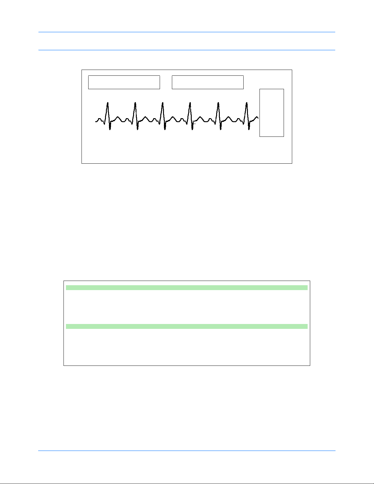
Bedside Monitors
CST
RETRIEVE DATA CANCEL TRANSFER
E
C
G
Module: Jones, B
Monitor: Adams, S
Figure 3-6: Retrieving Transfer Data display
When you touch the RETRIEVE DATA key, the monitor displays YES and NO keys along with the
following message:
YES purges the monitor's data and retrieves data from the module.
NO cancels this action.
Touch NO to return to the previous screen. Touch YES to transfer the data from the module into the receiving
monitor and purge any data previously stored in that monitor.
Once you initiate data retrieval, the monitor removes all data-transfer-related keys from the ECG display zone
and displays the message TRANSFERRING PATIENT DATA INTO MONITOR. When the data retrieval into
the monitor is complete, the message DATA TRANSFER COMPLETED appears for one minute.
To receive transferred data:
• Touch RETRIEVE DATA.
• Touch YES.
To cancel data transfer:
• Insert the module into the receiving monitor.
• Touch CANCEL TRANSFER.
• Touch YES.
Ultraview SL Operations Manual 3-18
Page 59
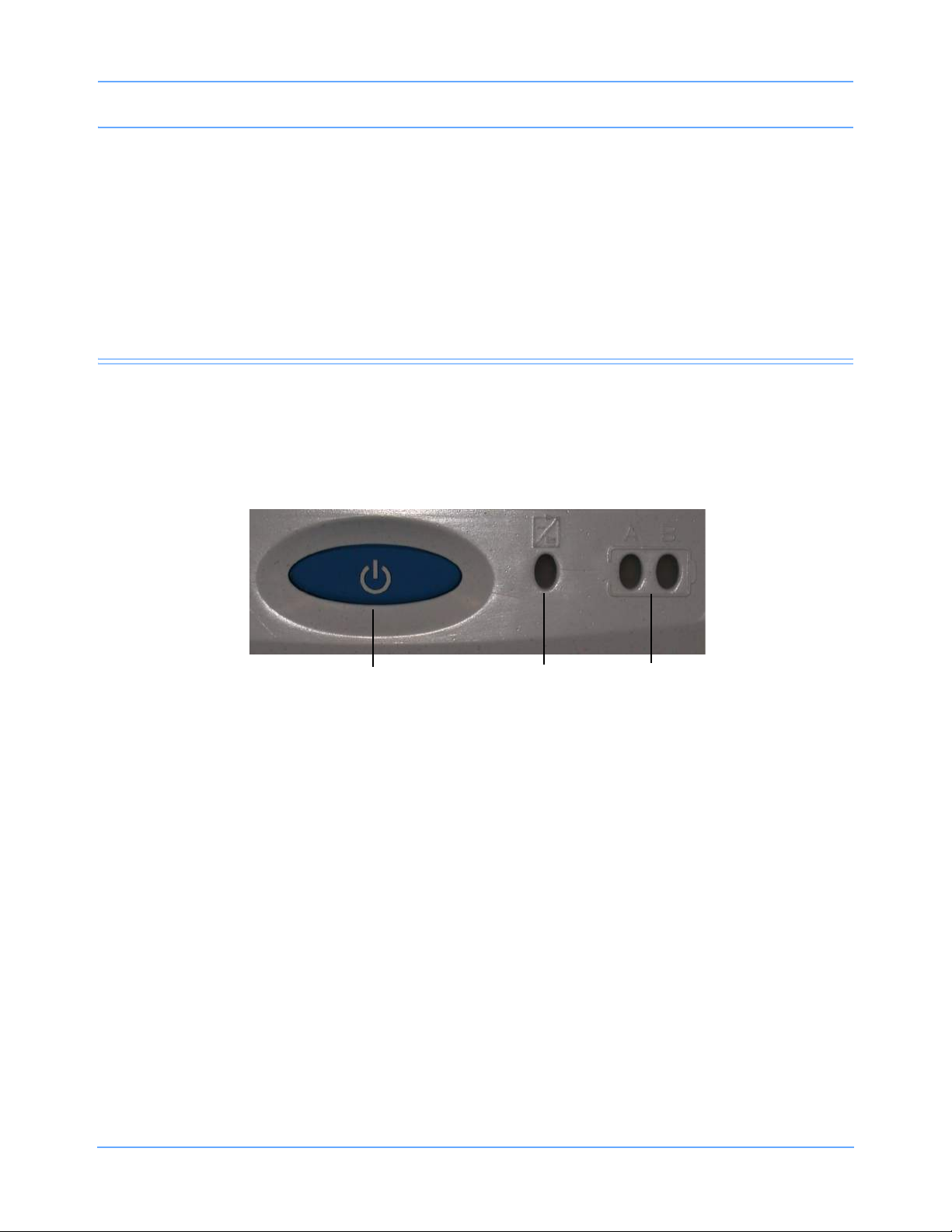
Bedside Monitors
INSERT GRAPHIC HERE
Power LED Battery status
LEDs
ON/OFF button
Canceling the Data Transfer After Module Insertion
To cancel a data transfer, touch the CANCEL TRANSFER key.
The monitor displays YES and NO keys along with the following message:
YES purges the data previously transferred into the module.
NO cancels this action.
Touch YES to confirm the cancellation of the data transfer and reactivate the TRANSFER DATA key in the
ECG Setup menu. Touch NO to return to the previous screen.
Power and Battery Status (SL2400/SL2600 Only)
The three LEDs on the SL2400/SL2600 monitor indicate whether the monitor is connected to the AC mains
power and the status of any installed batteries. Battery status conditions are indicated as described in the
following sections.
Figure 3-7: Battery status information
Power LED
The power LED is located immediately to the right of the ON/OFF button. This LED is lit whenever the monitor
is connected to AC mains power via its power supply, and is not lit if the monitor is not connected to the AC
mains power.
Battery LEDs
Solid Green LED
A solid green battery LED indicates that the battery is fully charged. Only a charging cycle or a faulty battery
will cause the green LED to flash, and these conditions only occur when a battery is installed in the monitor.
Ultraview SL Operations Manual 3-19
Page 60

Bedside Monitors
Flashing Green LED — Battery Charging
A flashing green battery LED indicates an installed battery is being charged and the monitor is not ready for
portable use. This LED flashes in a constant pattern with no delays with the monitor powered ON or OFF. The
flashing is different than the battery fault detection flash.
Note:
The green LED stops flashing and glows solid when the charging cycle is complete.
Intermittent Flashing Green LED — Battery Fault Detected
An intermittent flashing green LED indicates that the installed battery will not hold a charge or that it is taking
too long to charge. The intermittent signal is a repeating pattern of a solid green LED for one second and a
flashing LED for one second. An error message is also added to the error log for review by your system
administrator.
To determine whether a battery is faulty, power the monitor ON using the front-panel switch and observe the
message that appears along the bottom of the monitor display. Replace a faulty battery with the same battery
type.
Unlit LED
A battery LED that is neither solid ON nor flashing indicates that a battery is not present.
Battery Gauge
The battery gauge is always present in the lower right corner of the display when the monitor is operating on
batteries (powered ON and not plugged into AC power). This gauge indicates the approximate battery
capacity.
For example, the gauge will display:
• A fully charged battery
• ¾ battery charge remaining
• ½ battery charge remaining
• ¼ battery charge remaining
• Minimum battery charge remaining
Note:
• Printing drains large amounts of power and can cause the monitor to power OFF without warning.
Therefore, printing is automatically inhibited when the battery power reaches the ½ charge remaining.
• When the battery power becomes critically low (approximately ¼ charge remaining), the entire battery
gauge flashes to emphasize this warning. The monitor may power OFF at any time, depending upon
how much power the monitor is using.
• Upon power OFF, the monitor will cease to function.
Ultraview SL Operations Manual 3-20
Page 61

Bedside Monitors
SL2400/SL2600 Monitor Connections
External Power Supply and Network Connections
The connection for the external power supply is shown in Figure 3-8. The green LED to the right of the
ON/OFF button on the front panel is ON whenever the unit is powered by an external power supply.
To connect to an external power supply:
• Attach the DC outlet cable to J1.
• Connect the power cord of the external power supply to an AC outlet.
To connect to the 10/100BaseT port for network communication:
• Plug either end of an Ethernet cable into the modular jack connection on the side of the
monitor (refer to Figure 3-9 on page 3-22).
Network communication is done through the 10BaseT cable assembly only.
• Plug the other end of the cable into the wall in a wall plate with an 8-pin modular jack
connector.
Figure 3-8: SL2400/SL2600 power connection
J1 - external power supply connection
Ultraview SL Operations Manual 3-21
Page 62
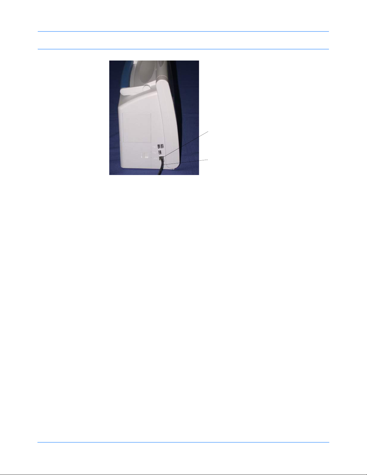
Figure 3-9: SL2400/SL2600 10/100BaseT network connection
Modular jack connection
10/100BaseT Ethernet cable
Bedside Monitors
Ultraview SL Operations Manual 3-22
Page 63
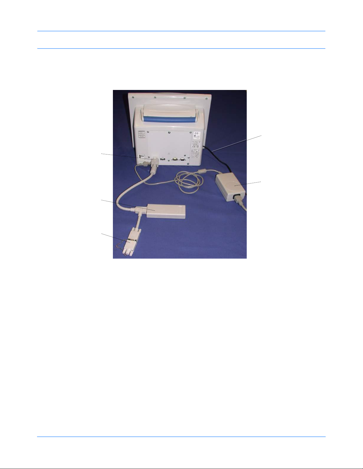
Bedside Monitors
External Flexport System Interface Connection
The SL2400/SL2600 monitors also provide an external Flexport system interface connection
(refer to Figure 3-10).
Figure 3-10: SL2400/SL2600 monitor power and Flexport connections
SDLC terminator
Flexport system interface
SDLC connection
10/100BaseT Ethernet cable
External power supply
Ultraview SL Operations Manual 3-23
Page 64

Bedside Monitors
Bedside Monitor Troubleshooting Guide
Clinical Situation Possible Cause Solution
Cannot change parameter
priority or colors
Changed parameter
priority or colors are lost
SL2400/SL2600 monitor
has no DC power
n Monitor may not be set up to
allow the user to change priority
or colors.
n The STORE key was not touched
after the selection was made.
n The monitor was not plugged into
an AC outlet while not in use.
n No batteries installed. n Install one or two batteries.
n Contact your system
administrator.
n Touch the STORE key to make
changes permanent.
n Plug the monitor into an AC
outlet to recharge batteries.
Ultraview SL Operations Manual 3-24
Page 65
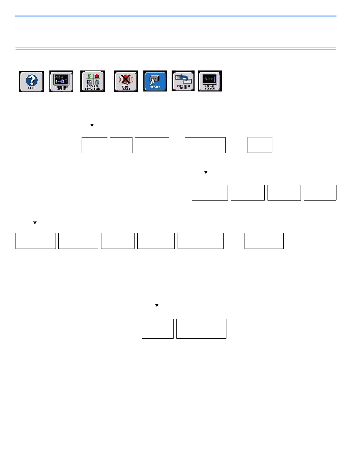
Central Monitors
Directory of Keys
Refer to
Introduction
MONITOR SETUP
SCREEN
FORMAT
Select the
waveform zone
Refer to
Alarms
SPECIAL FUNCTIONS
ALARM
WATCH
TONES
Refer to Alarms Refer to
AW
OFF
Refer to Alarms Select a bed Refer to
ADMIT/
DISCHARGE
Admit/Discharge
Refer to
Printing
ALARM LIMIT
REVIEW
MONITOR
CONFIG.
Refer to Introduction
REMOTE
TRENDS/CALCS
page 5-1
TRENDS/CALCS for BED XXX
GRAPHIC
TRENDS
RECORDER
CONFIG.
Refer to Printing Refer to
TABULAR
TRENDS
Refer to Trends and Calculations
PRIVILEGED
page 4-2 and
DNA
ACCESS
page 4-3
CALCS
DRUG
CALCS
Select the bed
(or subnet and
then the bed)
Select the
parameter
MONITOR CONFIGURATION
CLOCK
ON OFF
Ultraview SL Operations Manual 4-1
ACTIVATE SCREEN
SAVER
Page 66

Privileged Access
Central Monitors
Refer to
Introduction
MONITOR SETUP
PRIVILEGED
ACCESS
Enter clinical
password
and touch
ENTER
CLINICAL LEVEL - Select Parameter
TIME/
DATE
PRESELECTED
RECORDINGS
Refer to
Printing
UNITS OF
MEASURE
USER ACCESS - Enable user access to functions
Refer to
Alarms
PATIENT TYPE PARAMETER CONFIG RECORDING DURATION SUBNET ACCESS
ON OFF ON OFF ON OFF ON OFF
Refer to
Printing
USER
ACCESS
Refer to Introduction
ALARM
SETUP
Refer to
page 4-3
ALARM WATCH
SETUP
Refer to
page 4-3
MORE
Refer to
page 4-3
Restart monitor after selecting units of measurement
mmHg inches lb
kPa cm kg
MONITOR SETUP - Time/Date 10:06 AM
TIME
DATE PM
Ultraview SL Operations Manual 4-2
24
HOURS
AM
HOURS MINUTES
ENTER
Page 67

Privileged Access (continued)
Central Monitors
Refer to
Introduction
MONITOR SETUP
PRIVILEGED
ACCESS
Enter clinical
password
and touch
ENTER
CLINICAL LEVEL - Select Parameter
TIME/
DATE
Refer to
page 4-2
PRESELECTED
RECORDINGS
Refer to Printing Refer to
Refer to
Alarms
UNITS OF
MEASURE
page 4-2
Refer to
Printing
USER
ACCESS
Refer to
page 4-2
Refer to Introduction
ALARM
SETUP
ALARM WATCH
SETUP
CLINICAL LEVEL - Select Parameter
REMOTE KEYPAD
STATION ADDRESS
CHANGE CLINICAL
PAS SWOR D
MORE
RESET
MONITOR
Refer to Remote Keypad
ALARM WATCH SETUP - Select parameter to change
ROTATE ALARM WATCH ALARM WATCH ROTATION ROTATION TIME
ON OFF PRIORITY SIMPLE 15 S 30 S
ALARM SETUP - Select parameter
REMOTE ACCESS
ON OFF ALWAYS DURING ALARM SINGLE TRIPLE
ALARM
RELAY
QRS/SPO2 TONE ENABLE ALARM WATCH TONE
Ultraview SL Operations Manual 4-3
Page 68

Page 69

Central Monitors
Contents
Overview. . . . . . . . . . . . . . . . . . . . . . . . . . . . . . . . . . . . . . . . . . . . . . . . . . . . . . . . . . . . . . . . . . . . . . . . . . . . . 5
Display Detail . . . . . . . . . . . . . . . . . . . . . . . . . . . . . . . . . . . . . . . . . . . . . . . . . . . . . . . . . . . . . . . . . . . . . . . . . 6
Central Monitor Setup. . . . . . . . . . . . . . . . . . . . . . . . . . . . . . . . . . . . . . . . . . . . . . . . . . . . . . . . . . . . . . . . . . . 6
Central Monitor Troubleshooting Guide . . . . . . . . . . . . . . . . . . . . . . . . . . . . . . . . . . . . . . . . . . . . . . . . . . . . 10
Overview
The SL3800 central monitor provides full monitoring control of remote parameters, including displays and
alarms with both visual and audible annunciation. All waveform and current numeric data, arrhythmia, ST
segment, and trends are available with central monitoring.
Spacelabs Healthcare monitors and modules have built-in error detection and recovery circuitry that, together
with special software, allow the monitor to re-initialize and continue to function if an error occurs. Spacelabs
Healthcare monitors also provide battery backup to ensure that patient information is not lost in the event of a
short-term power interruption, such as backup generator testing.
When the system detects an error that cannot be corrected through other means, the central monitor reinitializes or resets (blanks). Normally, a reset involves very little loss of patient monitoring time (approximately
five seconds) and, with few exceptions, all user settings (alarm limits, pressure labels, transducer offsets, etc.)
are retained. The entire process of restoring the central monitor following a reset takes approximately
20 seconds, depending upon the number of parameters being monitored.
In some cases, stored trend data is lost when the monitor resets. Typically, this is indicative of a hardware
condition requiring corrective action. In this case, the system initiates the start-up diagnostics to check the
monitor's operation so that full recovery takes approximately 10 seconds longer.
If a bedside monitor resets, the central and bedside monitors may display the CHECK SETUP key (refer to
Check Setup on page 3-6) in the ECG zone to alert you to check all limits and values and ensure that the
monitors have restored all preset values. This also occurs when the monitors are powered ON, or when an
ECG module has been inserted.
Warning:
• If the equipment is dropped, abused, or damaged in any way (if the monitor or module becomes
wet, for example), a qualified field service engineer or biomedical engineer must verify that the
unit is working correctly and that all safety features are intact.
• Because of the potential for electromagnetic interference, electronic devices (for example,
portable communication transmitters, cellular telephones, personal computers, electronic toys,
and other medical devices) should not be operated within 3.5 feet (1.07 meters) of the patient,
patient leads, or associated monitoring equipment until evaluated by the biomedical
engineering staff.
Ultraview SL Operations Manual 4-5
Page 70

Central Monitors
24 Feb 04
21 Jan 06
Display Detail
The central monitor can accommodate up to 8 full-width display zones, or up to a maximum of 12 or
16 half-width zones on a split-view display. The SIX-TRACE-mode automatically reformats the display to
increase the font and zone sizes for alphanumeric text. The larger font and zone sizes always appear on
central monitors configured for 4-, 5-, 6-, and 12-zone operation, because no more than 6 full zones can have
parameters assigned to them.
Note:
• When measured parameter values are above the monitor’s designated range, then these symbols
appear in place of numerics:
• When measured parameter values are below the monitor’s designated range, then these symbols
appear in place of numerics:
+++.
---.
Figure 4-1: Split-view display option showing 16 zones
Central Monitor Setup
Many central monitor setup features are identical to those of the bedside monitor.
Refer to the following referenced sections for descriptions of these features:
• Clock menu (refer to Setting the Time and Date on page 3-15)
• Screen saver (refer to Activating the Screen Saver on page 3-13)
• Date/Time (refer to Setting the Time and Date on page 3-15)
• QRS tones (refer to Setting QRS Tones on page 3-15)
Ultraview SL Operations Manual 4-6
Page 71
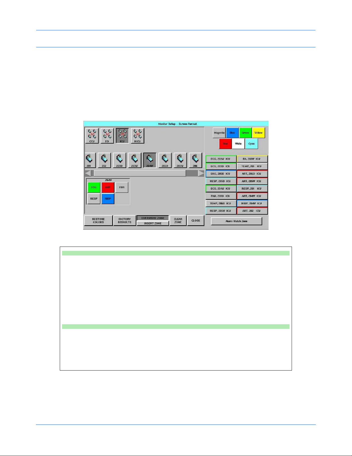
Central Monitors
Selecting Parameters for Display
The SCREEN FORMAT key in the Monitor Setup menu enables you to assign remote parameters to specific
display zones and to choose the color of those zones. The names displayed in the subnet and bed keys are
assigned by your system administrator.
One to eight display zones can be viewed across the entire display. Split-view central monitors can
accommodate up to 16 display zones, with zones 1 through 8 displayed on the left and zones 9 through
16 displayed on the right.
Figure 4-2: Screen Format dialog box, split-view central monitor
To select remote parameters for display:
• Touch MONITOR SETUP.
• Touch SCREEN FORMAT.
• Select a bed.
-OR-
• Select a subnet and then a bed.
• Select the parameter(s) to be displayed.
• Select a zone.
To assign color to a zone:
• Touch MONITOR SETUP.
• Touch SCREEN FORMAT.
• Touch the desired color.
• Touch the zone to be colored.
Ultraview SL Operations Manual 4-7
Page 72

Central Monitors
The other Screen Format (Figure 4-2) keys function as follows:
• RESTORE COLORS — Restores the last stored color settings from memory.
• FACTORY DEFAULTS — Restores the factory-default color settings.
• OVERWRITE ZONE — Overwrites a zone that was previously assigned. Select the new parameter and
then touch OVERWRITE ZONE to remove the previously assigned parameter channel from the display
zone and replace it with the new parameter.
• INSERT ZONE — Inserts a new zone into a block of assigned zones. Touch INSERT ZONE, then touch
the location where you wish to add a new zone. If a zone is inserted on top of an assigned zone, then the
assigned zone and all other zones immediately adjacent to the assigned zone are pushed down by one
zone, and the new zone is inserted above them. If this causes an assigned zone to disappear from the
display, a warning message appears prompting you to complete or cancel the insert.
• CLEAR ZONE — Clears the zone assignment and returns that zone to an unassigned state. Touch
CLEAR ZONE, then touch the zone from which you wish to remove an assignment. The zone key label is
cleared.
Data Communications Watch
Note:
A system administrator with biomed level privileges controls the Data Communications Watch feature.
The central monitor’s Data Communications Watch (DCW) feature displays a Data Communications
Interrupted (DCI) notice when its communication link with a bedside monitor is interrupted. This DCI notice
replaces each channel that was lost due to the communication interruption. Possible causes of such
interruptions include when the bedside monitor is powered OFF or is disconnected from power, a network
failure occurs, or when other circumstances prevent communication from occurring.
The DCI notice includes the bed name, patient identification string, the parameter key of the lost channel, and
keys labeled YES and NO (as shown in Figure 4-3). The time and date that communication was lost can be
determined by touching the lost parameter’s key and noting the message that appears at the bottom of the
display.
DATA COMMUNICATIONS INTERRUPTED
REMOVE PATIENT ZONE(S)?
E
C
YES NO
BED 01
G
Figure 4-3: DCI notification screen
An optional low priority alarm occurs if the DCI alarm is enabled. When that alarm is enabled, the parameter
key of the lost channel flashes and an alarm tone sounds.
Ultraview SL Operations Manual 4-8
Page 73

Central Monitors
The YES and NO keys control the central station’s continued display of the lost channels as well as the
optional DCI alarm. All of a bedside monitor’s DCI notices are controlled by any of the YES and NO keys in its
display zones.
Selecting YES removes every DCI notice for that bedside monitor from the central monitor’s display and ends
the DCI alarm. Selecting NO ends the DCI alarm without removing that bedside monitor’s DCI notices from the
display and disables the NO key.
Central monitors attempt to restore communication with the remote monitor, unless something else is assigned
to that display zone. The patient data is automatically restored once communication is restored.
Your central monitor may be configured to watch for communication interruptions involving monitors for all
patients, or only for monitors that have had patients admitted to them. Your system administrator controls this
configuration option as well as the optional DCI alarm.
Ultraview SL Operations Manual 4-9
Page 74

Central Monitors
Central Monitor Troubleshooting Guide
Clinical Situation Possible Cause Solution
Cannot assign color to
a zone
Cannot assign a
parameter to a zone
Cannot access the
clock menu
Cannot deselect
ALARM WATCH
n Monitor may not be set up to
allow you to assign colors.
n Zone may not have been cleared
of previously assigned
waveforms.
n Clock may be in STOPWATCH or
TIMER mode.
n The central monitor is
configured with Central Alarm
Watch Manager to prevent
de-selection of automatically
alarm-watched beds.
n Contact your system
administrator.
n Select CLEAR ZONE, then touch
the zone in which to display the
new parameter. Repeat the initial
SCREEN FORMAT steps.
n Touch the clock/timer display, then
touch PREVIOUS MENU to
restore the clock.
n Contact your system
administrator.
Ultraview SL Operations Manual 4-10
Page 75

Dynamic Network Access (DNA)
Directory of Keys
Refer to
Introduction
Refer to
Alarms
Refer to
Printing
Refer to Introduction
SPECIAL FUNCTIONS (Central Monitor—SL3800)
ALARM
WATCH
Refer to
Introduction
AW
OFF
ALARM LIMIT
REVIEW
SPECIAL FUNCTIONS (Bedside Monitor—SL2600 and SL2800)
REMOTE
VIEW
Refer to
Introduction
ALARM
WATCH
Refer to
Introduction
RV/AW
OFF
ALARM LIMIT
REVIEW
LOCAL TRENDS/
CALCS
TRENDS/CALCS
REMOTE
TRENDS/CALCS
REMOTE
DATA
LOGGER
DNA
DNA
Ultraview SL Operations Manual 5-1
Page 76

Page 77

Dynamic Network Access (DNA)
Contents
Overview. . . . . . . . . . . . . . . . . . . . . . . . . . . . . . . . . . . . . . . . . . . . . . . . . . . . . . . . . . . . . . . . . . . . . . . . . . . . . 3
Connection View. . . . . . . . . . . . . . . . . . . . . . . . . . . . . . . . . . . . . . . . . . . . . . . . . . . . . . . . . . . . . . . . . . . . . . . 5
Program Neighborhood View . . . . . . . . . . . . . . . . . . . . . . . . . . . . . . . . . . . . . . . . . . . . . . . . . . . . . . . . . . . . . 6
Overview
The Dynamic Network Access™ (DNA™) is a Spacelabs Healthcare proprietary version of the Citrix ICA Client
that provides the ability to connect and interact with the remote applications hosted on Citrix servers. DNA is
available as a standard feature on Ultraview SL2800 and 2900 bedside monitors and as an optional feature on
Ultraview SL2600 bedside monitors and Ultraview SL3800 and 3900 central monitors.
When using DNA on single-display monitor configurations (for example, SL2600, SL2800, and SL3800) the
DNA application window is superimposed over the monitoring display window. A custom window manager
maintains full integrity of all monitoring functions. In the event of a high-priority alarm, the DNA application
window will be minimized and the monitoring display window will be presented. Audible and visual alarm
indications will provide specific alarm information.
When using DNA on dual-display monitor configurations (for example, SL2900 and SL3900), the DNA
application window is presented on a second display independent of the monitoring display window. As such,
the DNA application window remains active throughout high-priority alarms.
The clinical user may only connect to a list of server locations or published applications. The list of server
locations or available applications must be configured by the biomed technician or system administrator
through the Privileged Access menu.
Your system administrator or other designated personnel must first set up communication between the
Ultraview SL monitor and server locations and/or applications before DNA can be used. The accessible
applications and servers are configurable. Refer to the 91370 Service Manual, P/N 070-1315-xx or the
91387 Service Manual, P/N 070-1159-xx, for information on DNA configuration.
Note:
Ensure that any computer or communications equipment connected to the network complies with
applicable medical standards.
To access DNA:
• Touch SPECIAL FUNCTIONS.
• Touch DNA.
Ultraview SL Operations Manual 5-3
Page 78

Dynamic Network Access (DNA)
Accessing DNA
1 From the Special Functions menu, touch DNA.
2The DNA window opens and displays either the Connection View or Program Neighborhood View.
What displays will depend on the configuration settings made at the biomed level.
- If DNA is configured to display a list of servers or connection definitions, then the Connection View
displays with its list of selectable connections.
- If DNA is configured to display a list of published applications, then the Program Neighborhood View
displays with its list of published applications.
When a tab view is open, the clinician may alternate between the Connection View and the Program
Neighborhood View.
DNA Application Window
The size and position of the DNA application window may vary. Its initial size and position is specified in the
DNA Setup menu. Refer to the 91370 Service Manual, P/N 070-1315-xx or the 91387 Service Manual,
P/N 070-1159-xx, for information on DNA configuration. Once the DNA application window is displayed, it may
be repositioned and resized. The monitor will retain the size and position until the next DNA session starts.
If the size of the DNA application window is smaller than the size required by the remote application, scroll bars
will be displayed that allow the user to move around the full application window.
Note:
When using DNA on a single-display monitor configuration, the DNA application window is automatically
minimized in the event of a high-priority alarm condition.
If a connection is made to a server, the window may be resized to what is specified in the connection setup.
Ultraview SL Operations Manual 5-4
Page 79
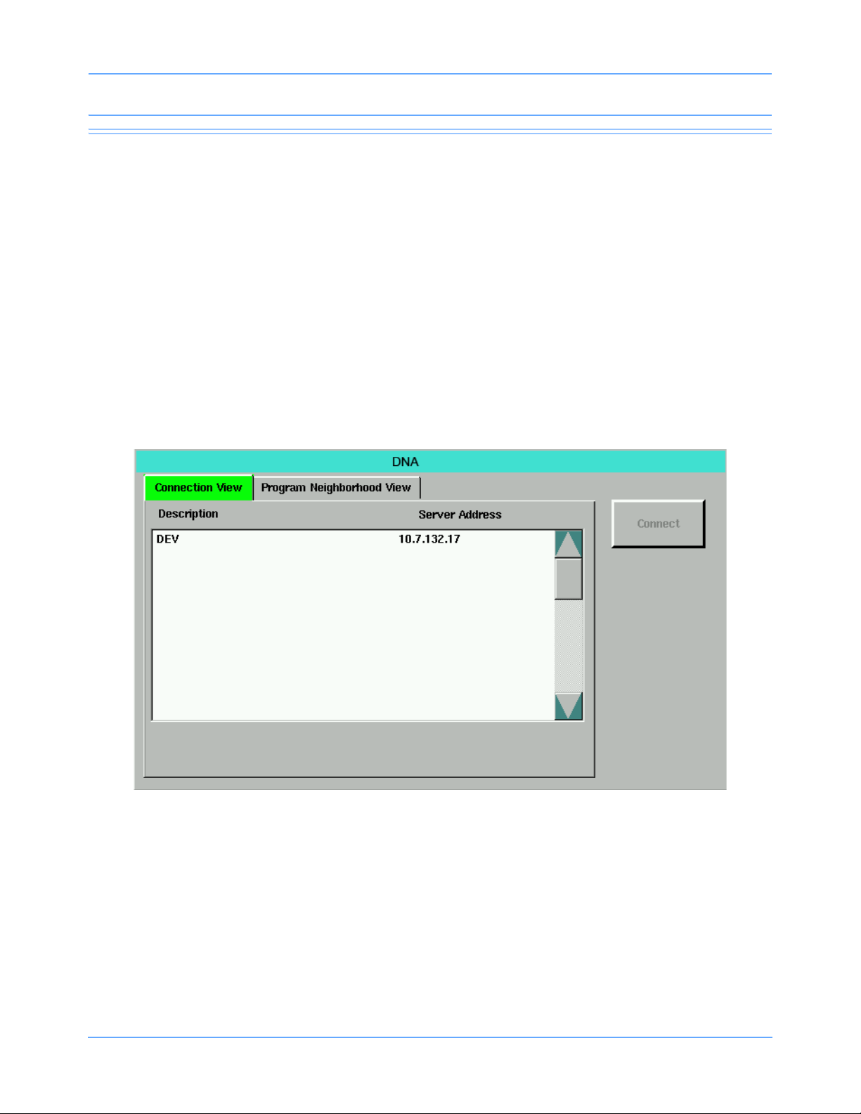
Dynamic Network Access (DNA)
Connection View
The Connection View displays a list of configured static connections that allow access to Citrix servers on the
network. Connections are listed by Description and Server Address.
Note:
A list of accessible servers must be previously configured through the Privileged Access menu.
Connecting To a Server
1 Double-click an item in the list.
2 Click or touch an item to select it, and then click or touch Connect (refer to Figure 5-1 on page 5-5).
Note:
Selecting an item in the list enables the Connect key.
Figure 5-1: Connection View
Ultraview SL Operations Manual 5-5
Page 80

Dynamic Network Access (DNA)
Program Neighborhood View
The Program Neighborhood View primarily displays a list of published applications with a dynamic list
acquired from a Citrix server or servers (refer to Figure 5-2 on page 5-6).
Note:
A list of accessible servers must be previously configured through the Privileged Access menu.
Connecting To a Published Application
Login credentials are required to access published applications from the Program Neighborhood View.
1 Touch Program Neighborhood View.
Program Neighborhood View initially opens with a blank scroll window (refer to Figure 5-2).
Note:
You must log in to view and connect to a list of published applications.
Figure 5-2: Program Neighborhood View before login
Ultraview SL Operations Manual 5-6
Page 81

Dynamic Network Access (DNA)
2 When the Login window opens, enter Username, Password, and Domain in the entry fields (refer to
Figure 5-3).
Figure 5-3: Login credentials window
3 Select the Save Password check box and touch Login.
• Selecting Save Password allows you to launch multiple published applications without having to
re-enter your login credentials.
• To save a password, you must select the Save Password check box on the Login window.
Note:
• Selecting the Save Password check box on the Login window automatically selects the Save
Password check box in Program Neighborhood View (Figure 5-4 on page 5-8).
• You may de-select the Save Password check box in Program Neighborhood View to “un-save” the
password of a user who is done launching published applications. This allows other users to log in to
and utilize the monitor.
-OR-
4 Touch Login without selecting the Save Password check box.
Note:
If you choose to not select Save Password, you must log in every time you attempt to connect to any other
applications through the Program Neighborhood View.
-OR-
5 Touch Cancel to exit the Login window and return to the Program Neighborhood View.
Ultraview SL Operations Manual 5-7
Page 82
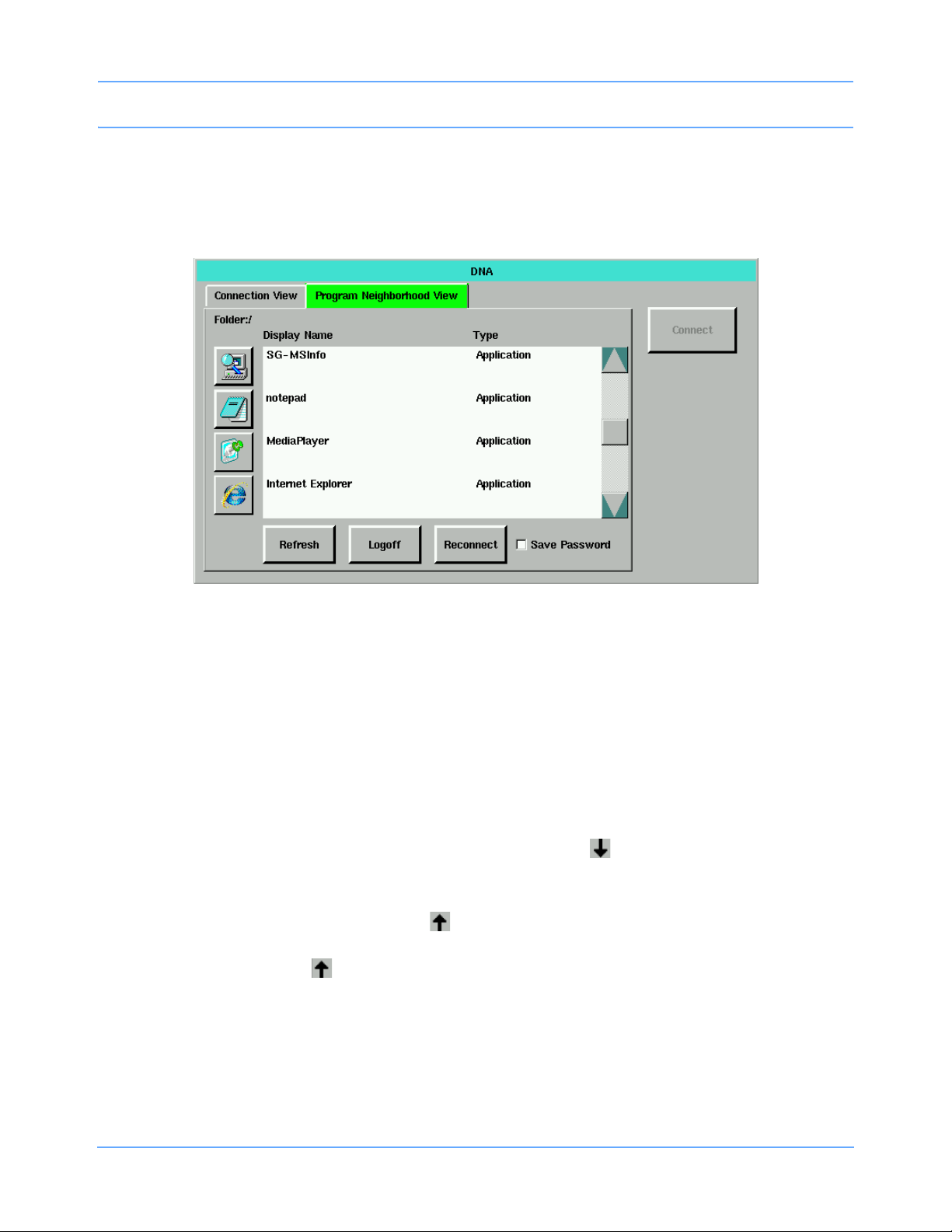
Dynamic Network Access (DNA)
After logging in, the Program Neighborhood View is populated with a list of published applications
(Figure 5-4). Up to 128 items may be listed in the Program Neighborhood View.
Note:
Selecting an item in the list enables the Connect key.
Figure 5-4: Program Neighborhood View
6 Scroll through the Display Name/Type list to select an application. Three types may be listed in this
window:
• Applications or server desktops
- Desktops are indicated by a server address.
- Only one application at a time may be utilized.
• Content (text files, Word documents, etc.)
These file types will execute specific applications. Each file type is used to find the appropriate
published application to run.
• Folders (a one-level subdirectory represented by a down arrow ). Up to five applications may be
housed in each folder.
- Selecting the down arrow displays the contents of the folder.
- When the folder is open, an up arrow appears as the first entry. The first entry name displays as
“..”.
- Touch the up arrow to return to the top level application display.
There are three ways to launch a published application.
7 Double-click a Display Name entry.
-OR-
8 Click or touch the Display Name entry to select it, then click or touch Connect.
Ultraview SL Operations Manual 5-8
Page 83

Dynamic Network Access (DNA)
-OR-
9 Click or touch the icon located to the left of the Display Name entry.
The icons to the left allow easy startup of the applications. They scroll in sync with the window of listed
items on the right.
10 Touch Reconnect to attempt to reconnect to a disconnected session.
11 Touch Refresh to query the server for a fresh list of applications.
12 Touch Logoff to log out from the Program Neighborhood View window.
Note:
Touching Logoff requires you to log back in to the Program Neighborhood View if you have not selected
Save Password. Connection View is still accessible.
13 Click or touch the minimize icon in the upper right corner of the DNA application window (refer to
Figure 5-5) to minimize the DNA application window, but leave the DNA session running.
Figure 5-5: DNA application window with open application
14 From the Special Functions menu, touch the DNA key on the monitoring display window to restore the
minimized DNA application window.
Ultraview SL Operations Manual 5-9
Page 84

Dynamic Network Access (DNA)
15 Click or touch the logoff icon (refer to Figure 5-5) to close an open DNA application.
If you touch the DNA key during a DNA session when the DNA application window is not minimized,
a small logoff window displays (refer to Figure 5-6).
-OR-
If you click or touch the logoff icon, the Logoff window displays (refer to Figure 5-6).
Figure 5-6: Logoff window
16 Touch Logoff to terminate the application and disconnect the current DNA session.
17 Touch Disconnect to disconnect the current DNA session, but leave the application running.
18 Touch Cancel to remain connected to the current DNA session.
Note:
Once an application is launched, the DNA key will not allow the launching of another application or desktop
until the existing session has terminated. To run multiple applications simultaneously, you must open
a desktop and launch the applications from within the desktop session.
Ultraview SL Operations Manual 5-10
Page 85

Perioperative
Directory of Keys
Refer to
Introduction
MONITOR SETUP
TONES
Refer to
Alarms
DISCHARGE
Admit/Discharge
ADMIT/
Refer to
Refer to
Alarms
PRIMARY
CONFIG.
Option -D only Option -D
Refer to
Printing
SECONDARY
CONFIG.
SL2600/
SL2700/SL2800
monitors
only
MONITOR CONFIGURATION - SECONDARY MONITOR
MINOR
GRATICULE
Refer to Introduction
RECORDER
CONFIG.
Refer to Printing Refer to Bedside
PARAMETER
CONFIG
PRIVILEGED
ACCESS
Monitors
CLOCK
ON OFF
MINOR GRATICULE - N Divisions
MINOR GRAT
ON OFF
MONITOR CONFIGURATION - PRIMARY MONITOR
ENERGY SAVING MODE SCREEN BRIGHTNESS
ON OFF OR NORMAL DIM ON OFF ON OFF
DC Power
SL2400/SL2600 only
Refer to Bedside Monitors
Ultraview SL Operations Manual 6-1
AC Power
SL2400/SL2600 only
Refer to Bedside Monitors
MINOR
GRATICULE
Refer to
Bedside
Monitors
PARAMETER
CONFIG
CLOCK ALARM LIGHT
Refer to
Bedside
Monitors
SL2400/
SL2600 only
Refer to
Bedside
Monitors
ACTIVATE
SCREEN SAVER
Refer to Bedside
Monitors
Page 86

Page 87

Perioperative
Contents
Overview. . . . . . . . . . . . . . . . . . . . . . . . . . . . . . . . . . . . . . . . . . . . . . . . . . . . . . . . . . . . . . . . . . . . . . . . . . . . . 3
Identifying Perioperative Functions. . . . . . . . . . . . . . . . . . . . . . . . . . . . . . . . . . . . . . . . . . . . . . . . . . . . . . . . . 3
Start Case/End Case . . . . . . . . . . . . . . . . . . . . . . . . . . . . . . . . . . . . . . . . . . . . . . . . . . . . . . . . . . . . . . . . . . . 4
User Preference Configurations . . . . . . . . . . . . . . . . . . . . . . . . . . . . . . . . . . . . . . . . . . . . . . . . . . . . . . . . . . . 8
Secondary Display . . . . . . . . . . . . . . . . . . . . . . . . . . . . . . . . . . . . . . . . . . . . . . . . . . . . . . . . . . . . . . . . . . . . . 6
Perioperative Troubleshooting Guide . . . . . . . . . . . . . . . . . . . . . . . . . . . . . . . . . . . . . . . . . . . . . . . . . . . . . . 13
Overview
Perioperative features extend the functionality of Spacelabs Healthcare monitors and modules to the operating
room. Perioperative features include START CASE/END CASE keys on the monitor; a configurable secondary
display; and extended user-configurable display preferences.
Identifying Perioperative Functions
If your monitor was purchased with the Perioperative option, additional keys identifying those perioperative
functions appear in the Monitor Setup menu and on the monitor’s menu line keys. Perioperative features
include:
START CASE and END CASE keys — These keys (refer to Figure 6-1) control the operation of the
monitor and modules by case, and silence audible alarms when the alarms are not needed. However,
visual alarm indicators will continue to display upon END CASE, unless ALARM SUSPEND is pressed.
Remote Configurable Display — A secondary display that is controlled from the monitor’s Monitor Setup
menu, using the SECONDARY CONFIG. key, and from the menu line, using the SECONDARY CONTROL
key (refer to Figure 6-1). The parameter attributes of the secondary display can be configured differently
than the primary display.
User Preference Configurations — Parameter display configurability is extended by supporting named sets
of configurations for the primary and secondary displays. Up to five separate configurations can be set for
individual users or case types.
Ultraview SL Operations Manual 6-3
Page 88
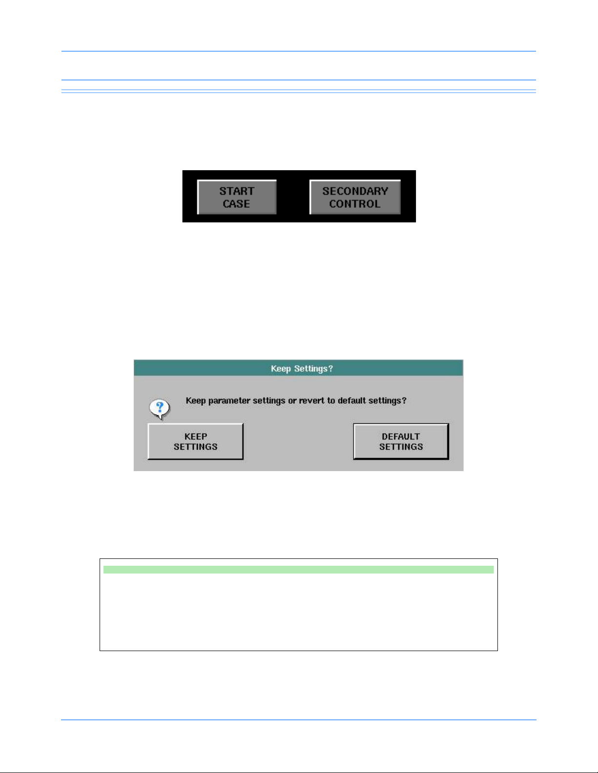
Perioperative
Start Case/End Case
When enabled, the monitor displays a key labeled START CASE or END CASE with the menu keys along the
bottom of the monitor’s display. The key will toggle to the opposite state when touched and confirmed.
Figure 6-1: START CASE/END CASE and SECONDARY CONTROL menu line keys
Starting a Case
Touch START CASE to start a patient case. The Keep Settings? dialog box displays. The KEEP SETTINGS
key allows you to keep all user-configured parameter module settings.
The DEFAULT SETTINGS key restores the parameter modules to the default settings specified in Module
Configuration Manager. For more information, refer to the Ultraview SL Module Configuration Manager System
Administration Guide (P/N 070-1245-xx) or contact your hospital system administrator.
Figure 6-2: Keep Settings dialog box
Touching KEEP SETTINGS or DEFAULT SETTINGS will open a Purge Patient Data? confirmation window, if
the monitor is configured to query the user (contact your system administrator for details). Touching YES will
erase all patient data. Touching NO will retain patient demographic data.
To start a case:
• Touch START CASE.
• Touch KEEP SETTINGS.
• Touch YES to purge data, or touch
NO to keep patient data (if enabled).
Note:
If you accidentally touch START CASE, you can touch NORMAL SCREEN to prevent the case
from starting.
Ultraview SL Operations Manual 6-4
-OR-
• Touch DEFAULT SETTINGS.
• Touch YES to purge data, or touch
NO to keep patient data (if enabled).
Page 89

Perioperative
Ending a Case
You can end a case by touching the END CASE key. The End case? confirmation dialog box displays. Touch
END CASE in the End Case? dialog box to return to the monitoring window. The END CASE button toggles to
START CASE.
Figure 6-3: End case confirmation dialog
When a case is ended, alarm tones are OFF, but alarm monitoring continues, and visual indicators of alarms
continue to display. Remote alarm notification is prevented.
Warning:
• Ensure that the case is complete before touching END CASE. Before ending the case, ensure
that the patient is being monitored by other equipment or by a dedicated caregiver for a limited
time (such as when a patient is being transferred to a transport monitor).
• After a case is ended, ALARM SUSPEND should only be used if no patient is connected to the
monitor.
If you touch the ALARM SUSPEND key when the case is ended, visual and audible alarms will not re-initialize.
Touch ALARM SUSPEND again or touch START CASE to re-initialize visual alarms. Individual parameters
may treat an end case differently. Refer to the appropriate parameter chapter for descriptions of end case
functionality, if applicable.
To end a case:
• Touch END CASE.
• Touch END CASE on the End Case? dialog box.
Ultraview SL Operations Manual 6-5
Page 90
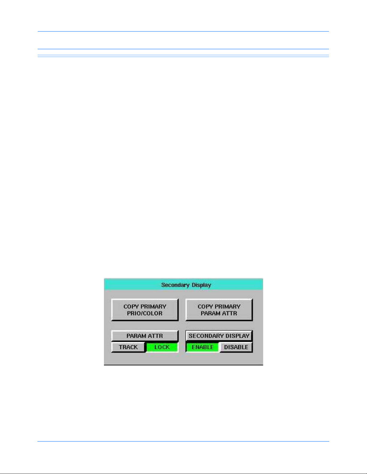
Perioperative
Secondary Display
The secondary display is configurable and can display different parameter information than is shown on the
primary display. The presentation of these parameters on the secondary display is also configurable.
The primary monitor is used to configure the secondary display. Refer to User Preference Configurations on
page 6-8 for information on configuring parameter priorities and colors for the secondary display.
Note:
• Support for the secondary display is not available for the SL2200 and SL2400 monitors.
• The secondary display has no functional keys or audio capabilities.
• When using the integrated Remote Configurable Display, option C, which is available for the SL2700
and SL2800 monitors, the secondary display provides a real-time representation of the waveform data.
Procedures requiring real-time waveform data can be performed by viewing either the primary or
secondary display.
Warning:
When using the 91388 Remote Display Controller, the secondary display provides a time-delayed
(approximately 2 to 3 seconds) representation of the waveform data. Procedures requiring
real-time waveform data must be performed by viewing the primary display.
Secondary Control
The SECONDARY CONTROL menu key (refer to Figure 6-1 on page 6-4) allows access to display functions
for the secondary display, without navigating through the MONITOR SETUP menu structure.
Touching the SECONDARY CONTROL key opens the Secondary Display dialog box.
Figure 6-4: Secondary Display dialog box
Ultraview SL Operations Manual 6-6
Page 91

Perioperative
SECONDARY DISPLAY ENABLE/DISABLE
Touching the SECONDARY DISPLAY ENABLE/DISABLE key controls the state of the secondary display.
To enable or disable the secondary display:
• Touch the SECONDARY CONTROL.
• Touch SECONDARY DISPLAY ENABLE or DISABLE.
Refer to Secondary Display Configuration on page 6-11 for descriptions of the COPY PRIMARY PRIO/
COLOR, COPY PRIMARY PARAM ATTR, and PARAM ATTR TRACK/LOCK keys.
Scaled Displays
The secondary display can display up to four scaled pressures simultaneously (refer to Pressure on
page 20-3). Monitors optionally display minor graticule lines that can be adjusted. Minor graticules are small,
dashed line segments that appear between the full-scale graticule lines.
Minor graticules can be independently adjusted on the primary display and the secondary display. Refer to
Using Scaled Displays on page 3-12 for information about adjusting the minor graticule on the primary display.
To adjust the scaled display on a secondary display:
• Touch MONITOR SETUP.
• Touch SECONDARY CONFIG.
• Touch MINOR GRATICULE.
• Select MINOR GRAT ON/OFF.
• Use the arrow keys to adjust.
System Clock
A system clock can be continually displayed in the lower right corner on the secondary display.
To access the clock menu for the secondary display:
• Touch MONITOR SETUP.
• Touch SECONDARY CONFIG.
• Touch CLOCK ON/OFF.
Ultraview SL Operations Manual 6-7
Page 92

Perioperative
User Preference Configurations
The PARAMETER CONFIG. keys, located under the Monitor Setup menu PRIMARY CONFIG. and
SECONDARY CONFIG. keys, allow you to set parameter priorities and colors on the primary and secondary
displays.
Setting Priorities and Colors
Each parameter displays in the order of its assigned priority. The highest priority appears at the top of the
display, with the number 1. The Parameter Config. (refer to Figure 6-5) window enables you to change the
priority and color of parameters.
Refer to Table 1 on page 3-11 for a list of default priorities and colors for each parameter.
Figure 6-5: Parameter Config. window, primary display
DISPLAY PRIORITIES
The DISPLAY PRIORITIES key lists all the current bed’s supported parameters (ALL), or a selected subset of
parameters (CUSTOM). Touching ALL will display all the monitor’s supported parameters.
Touching CUSTOM displays only the subset of parameters the user has selected, such as the parameters
used most frequently. You can configure up to five sets, which correspond to tabs 1 through 5 in the
Parameter Config. window.
Use the arrows keys to move the parameters between the CUSTOM LIST and the full parameters list. Or, if
parameters are already listed under CUSTOM LIST, touch a parameter from the full list, and then touch the
desired position under CUSTOM LIST. The new parameter replaces the position of the previous parameter
under CUSTOM LIST.
Ultraview SL Operations Manual 6-8
Page 93

Perioperative
Using the arrows keys to move the parameters from the full list to CUSTOM LIST places the parameter in the
lowest position. To change the order of a parameter, touch that parameter, then touch the position you wish to
place the parameter.
Note:
You can configure parameter priorities and positions without the parameter module present.
INSERT BLANK
The INSERT BLANK keys enable you to insert a space above or below a parameter. Blanks can be inserted by
touching the blank key and then inserting the blank key space into the desired location. After selecting a blank,
touch APPLY or SAVE. A blank zone then occupies the corresponding position on the display.
To remove a blank key, touch the blank key then touch the right arrow to move it out of the CUSTOM LIST.
SAVE
The SAVE key saves and applies any changes made to the priority and color settings. CHANGES NOT
SAVED displays in the Parameter Config. window until you save the settings. If you touch another tab without
saving changes, the previous tabs displays in red.
To retain configuration changes after the monitor is powered OFF, you must select SAVE.
APPLY
The APPLY key applies any changes made to the priority and color settings of the current display, but does not
save those changes when the monitor is powered OFF. Changes made to a configuration take effect after
touching APPLY.
To retain configuration changes after the monitor is powered OFF, you must select SAVE.
To change the primary display parameter priorities or colors:
• Touch MONITOR SETUP.
• Touch PRIMARY CONFIG.
• Touch PARAMETER CONFIG.
• Touch one of the tabs along the top of the Monitor Setup - Parameter Config.,
if necessary.
• Select a parameter.
• Touch the left arrow to move the first parameter into the CUSTOM LIST.
-OR-
• Select the destination priority by touching the position in the CUSTOM LIST column
(all subsequent parameters).
• Select a color.
• Select the parameter key to be colored (the key and waveform will appear in the
chosen color).
• Touch SAVE to store the local color and priority settings, or touch APPLY to only
display the settings.
Ultraview SL Operations Manual 6-9
Page 94
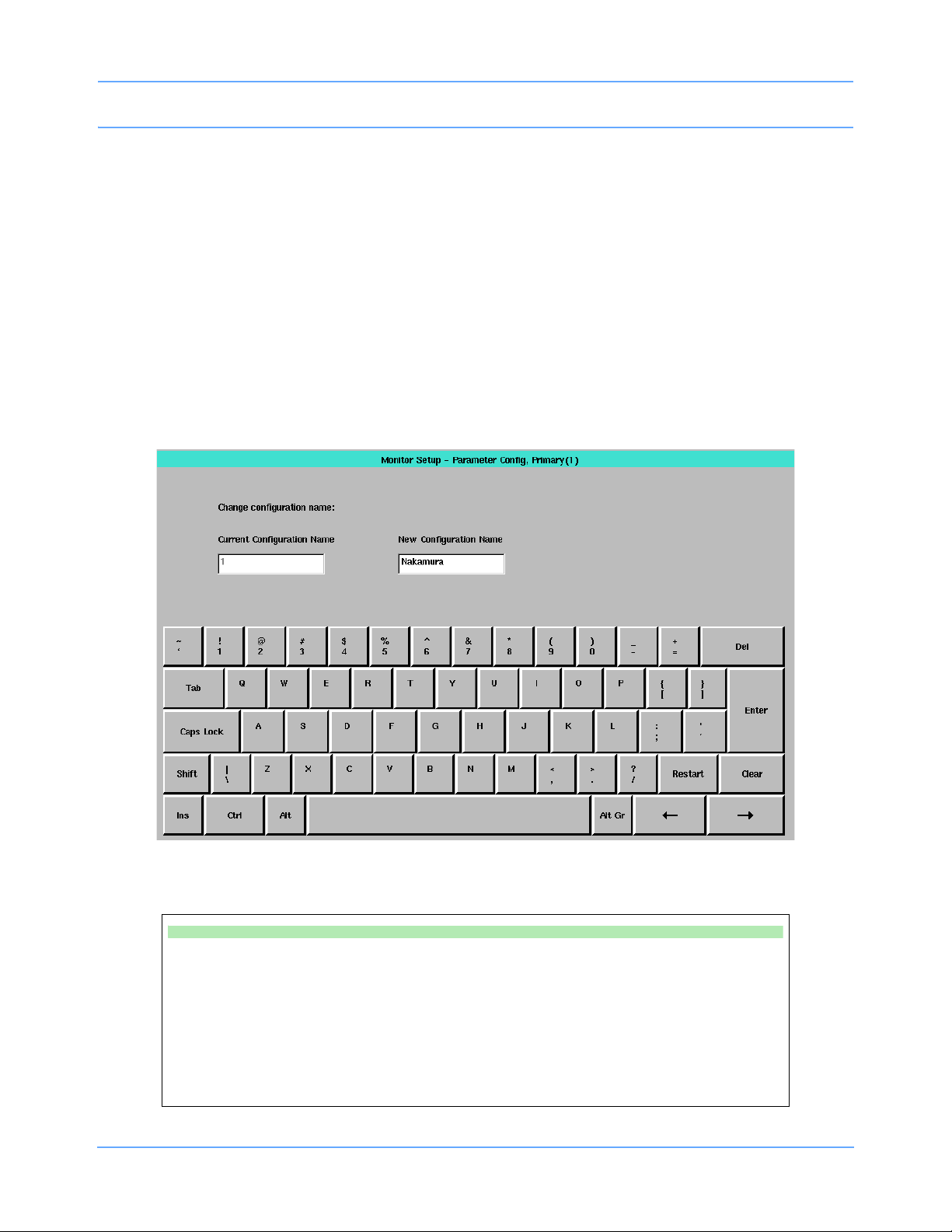
Perioperative
RESTORE
The RESTORE key discards any changes made to the settings that have not been saved. Touching
RESTORE, then touching APPLY, reverts to the last-saved settings.
FACTORY DEFAULTS
The FACTORY DEFAULTS key resets the factory-default priority and color settings, but does not save them.
You can continue to make configuration changes to the display.
RENAME
The RENAME key opens an on-screen keyboard (refer to Figure 6-6 on page 6-10). You can rename the
active tab with a name of up to 15 characters on SL2800, SL2700, and SL2600 monitors, and up to 8
characters on an SL2400 monitor.
Figure 6-6: Renaming a tab
To rename a Parameter Config. window tab:
• Touch MONITOR SETUP.
• Touch PRIMARY CONFIG. or SECONDARY CONFIG.
• Touch PARAMETER CONFIG.
• Touch a tab (1 through 5).
• Touch RENAME.
• Enter the new name.
• Touch Enter.
Ultraview SL Operations Manual 6-10
Page 95
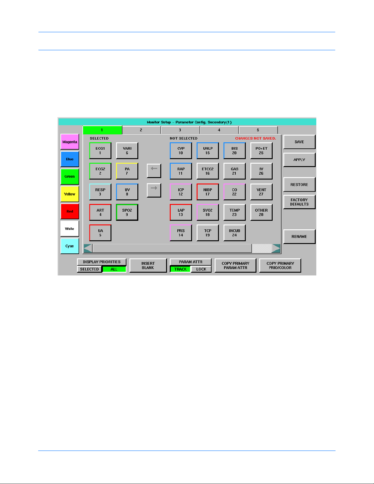
Perioperative
Secondary Display Configuration
The secondary Parameter Config. window includes several additional keys.
Note:
The secondary display can only be configured to display information for parameters that are being
monitored at the primary monitor.
Figure 6-7: Parameter Config. window, secondary display
PARAM ATTR TRACK/LOCK
Selecting PARAM ATTR TRACK or PARAM ATTR LOCK determines whether parameter attribute changes
made on the primary display are also made on the secondary display. The default setting is PARAM ATTR
TRACK.
The parameter attributes affected by PARAM ATTR TRACK/LOCK and COPY PRIMARY PARAM ATTR are
waveform size, sweep speed, and invasive pressure scales.
When PARAM ATTR TRACK is selected, all changes made to the primary display parameter attributes are
also made on the secondary display. When PARAM ATTR LOCK is selected, the secondary display maintains
its parameter settings, and any display changes made to the primary display do not affect the secondary
display.
Selecting PARAM ATTR TRACK does not immediately copy the primary displays parameter attribute settings
to the secondary display. Each setting is copied to the secondary when the next valid change is made to that
setting. You can use COPY PRIMARY PARAM ATTR to copy all display attributes from the primary to the
secondary display (refer to COPY PRIMARY PARAM ATTR on page 6-12).
Ultraview SL Operations Manual 6-11
Page 96

Perioperative
Note:
• Some multiple waveform parameter views such as ECG split-view and full-view displays, Multigas, and
BISx cannot be locked. Any changes to a parameter’s multiple waveform view are immediately visible
on the secondary display, even if PARAM ATTR LOCK is selected.
• Locking does not apply to parameters such as Varitrend, which “plot” data on the display. In these
cases the parameters always update on both the primary and secondary displays, even if PARAM
ATTR LOCK is selected.
• DNA windows cannot be displayed on the secondary display.
COPY PRIMARY PRIO/COLOR
Selecting this key copies the parameter color and priority settings of the primary display to the secondary
display.
The secondary Parameter Config. window updates immediately, and the secondary display updates when
you select SAVE.
COPY PRIMARY PARAM ATTR
Selecting this key copies the primary display’s parameter attributes, such as sweep speeds or waveform sizes,
to the secondary display. The secondary display updates immediately. Refer to PARAM ATTR TRACK/LOCK
on page 6-11 for more information.
To change the secondary display parameter priorities or colors:
• Touch MONITOR SETUP.
• Touch SECONDARY CONFIG.
• Touch PARAMETER CONFIG.
• Touch a tab.
• Select a parameter.
• Select the destination priority.
• Select a color.
• Select the parameter key to be colored (the key and waveform will appear in the
chosen color after touching APPLY).
• Touch SAVE to store local color and priority settings, or touch APPLY to only display
the settings.
Note:
The parameter will not appear on the secondary display unless it is selected and appears in the
SELECTED column.
Ultraview SL Operations Manual 6-12
Page 97

Perioperative
Perioperative Troubleshooting Guide
Clinical Situation Possible Cause Solution
No parameter output to
secondary display
Changed parameter
priority or colors are lost
Secondary display is too
dim or has poor contrast
The secondary display
output is distorted or
shows static or “noise”
n There is no communication
between the monitor and the
secondary display.
n The SAVE key was not touched
after the selection was made.
n The secondary display is not
optimized for brightness or
contrast.
n The display cable is too long, or
it is routed too close to a source
of interference.
n If using a 91388 Remote Display
Controller: Refer to the Remote
Display Controller Service Manual
(P/N 070-1330-xx) for setup and
configuration information.
n If using the Remote Configurable
Display, option C: Ensure the
second DVI output is connected to
the secondary display. If the display
cable length exceeds 9 feet,
third-party video repeaters must be
used. Refer to the video repeater
installation information for
configuration and limitations.
n Touch the SAVE key to make
changes permanent.
n Refer to the display user’s guide for
information on adjusting the display.
n If using a 91388 Remote Display
Controller: Refer to the Remote
Display Controller Service Manual
(P/N 070-1330-xx) for proper
cable lengths and positioning.
n If using the Remote Configurable
Display, option C, and the display
cable length exceeds 9 feet,
third-party video repeaters must
be used. Refer to the video
repeater installation information
for configuration and limitations.
Ultraview SL Operations Manual 6-13
Page 98

Page 99

Alarms
Directory of Keys
Adjusting Alarm Tones
Refer to
Introduction
Refer to
page 7-3
Refer to
Alarms
MONITOR SETUP
TONES
MONITOR
CONFIG
MONITOR CONFIGURATION
ALARM LIGHT
ON OFF
SL2400/SL2600
only
MONITOR SETUP - Select type of tone to change
LOCAL
ALARMS
REMOTE
ALARMS
ALARM
WATCH
KEY
TONE
MONITOR SETUP - LOCAL ALARM TONE
TONE
ON OFF
VOLUME
VOLUME
Refer to
Printing
Refer to Introduction
Ultraview SL Operations Manual 7-1
Page 100

Setting up Automatic Alarm Recordings
Alarms
Refer to
Introduction
Refer to
page 7-3
Refer to
Alarms
Refer to
Printing
Refer to Introduction
MONITOR SETUP
RECORDER
CONFIG.
RECORDER CONFIGURATION Number of recorder channels
RECORDING
DURATION
ALARM
PAR AMS
RECORDING
DESTINATION
124
Only appear if printer is
*4 channels supported by
present
90469 only
Alarm Recordings to Other Recordings to
Central
Bedside
THIS
MONITOR
NETWORK BOTH
THIS
MONITOR
Select Bed
VITALS
SETUP
SL2400/
SL2600 only
NETWORK
BED X ...
Select parameters that require alarm recordings from BED X
ECG RESP
ON OFF ON OFF
... MORE
Select duration for recordings initiated from this monitor
12 SEC 20 SEC
Ultraview SL Operations Manual 7-2
 Loading...