


BleaseSirius
Anesthetic Machine
Technical Manual
073-0227-00/REV. D1

2

BleaseSirius
Anesthetic Machine
With 700/900 Series Ventilators
Technical
Manual
|
MODIFICATIONS LABEL |
|
|
|
|
|
|
|
|
|
|||
|
|
|
|
|
|
|
|
|
|
|
|
|
|
|
ECO |
A |
|
REV |
B |
|
REV |
C |
REV |
D |
REV |
E |
|
|
PR023288 |
|
PR032030 |
|
PR033225 |
PR034475 |
|
|
|
||||
|
|
|
|
|
|
|
|
|
|
|
|
|
|
|
REV |
F |
|
REV |
G |
|
REV |
H |
REV |
I |
REV |
J |
|
|
|
|
|
|
|
|
|
|
|
|
|
||
|
|
|
|
|
|
|
|
|
|
||||
Spacelabs Healthcare Ltd. |
|
|
|
|
|
|
|
|
|
||||
1 Harforde Court • |
John Tate Road |
• Hertford |
|
|
|
|
|
|
|||||
SG13 7NW • United Kingdom |
|
|
|
|
|
|
|
|
|
||||
Tel: |
+44 (0)1992 507700 |
|
|
|
|
|
|
|
|
|
|||
Fax: |
+44 (0)1992 501213 |
|
|
|
|
|
|
|
|
|
|||
e-mail (enquiries): advsales@spacelabs.com |
|
|
Part Number: 073-227-00 |
||||||||||
e-mail (technical): advsupport@spacelabs.com |
|
|
|
Rev. D/ July 2013 |
|||||||||
www.spacelabshealthcare.com |
|
|
|
|
|
|
|
|
|||||
|
|
|
|
|
|
|
|
|
|
|
|
|
|
3

4

Important
Read this manual before operating or servicing the machine.
For all users and Service Personnel, refer to the User Manual before operating the machine.
© Copyright 2013, Spacelabs Healthcare Limited.
All rights reserved. The information contained in this publication may not be used for any other purpose than that for which it was originally supplied.
This publication may not be reproduced in part or in whole without the written consent of Spacelabs Healthcare.
5

This page is intentionally left blank
6

|
Contents |
|
Chapter 1-Technical Description............................................................... |
19 |
|
1.1 Description......................................................................................................... |
21 |
|
1.1.1 |
General ................................................................................................ |
21 |
1.1.2 |
The Frame............................................................................................ |
21 |
1.1.3 |
Pneumatic Assembly............................................................................ |
21 |
1.1.4 |
The Monitor Shelf................................................................................. |
21 |
1.2 Specifi cation ...................................................................................................... |
24 |
|
1.2.1 |
Machine Dimension.............................................................................. |
24 |
1.2.2 |
Work Surface Dimensions.................................................................... |
24 |
1.2.3 |
Monitor Shelf Dimensions .................................................................... |
24 |
1.2.4 |
Maximum Loading................................................................................ |
24 |
1.3 Pneumatics ........................................................................................................ |
25 |
|
1.3.1 |
Gas-Specifi c Color Specifi cations........................................................ |
25 |
1.3.2 |
Gas Supply Combinations.................................................................... |
25 |
1.3.3 |
Common Gas Outlet ............................................................................ |
25 |
1.4 Technical/Performance Specifi cation.............................................................. |
26 |
|
1.4.1 |
Controls................................................................................................ |
26 |
1.4.2 |
Ventilator .............................................................................................. |
26 |
1.4.3 |
Alarms / Indicators ............................................................................... |
26 |
1.4.4 |
Regulator Safety Valve Settings........................................................... |
26 |
1.4.5 |
Electrical............................................................................................... |
27 |
1.4.6 |
Supplies ............................................................................................... |
28 |
1.4.7 |
Environmental ...................................................................................... |
28 |
Chapter 2-Overview.................................................................................... |
29 |
|
2.1 Description of the Ventilator ........................................................................... |
31 |
|
2.1.1 |
Overview .............................................................................................. |
31 |
2.1.1.1 |
PEEP ................................................................................................... |
31 |
2.1.1.2 |
Trigger ................................................................................................. |
32 |
2.1.1.3 |
Support Pressure................................................................................. |
32 |
2.1.1.4 |
Fresh Gas Compensation.................................................................... |
32 |
7

Contents
2.1.1.5 |
Oxygen ................................................................................................ |
32 |
2.1.1.6 |
Tidal Volume ........................................................................................ |
32 |
2.1.1.7 |
Minute Volume..................................................................................... |
32 |
2.1.1.8 |
Expired Tidal volume ........................................................................... |
32 |
2.1.1.9 |
BPM (Frequency Control).................................................................... |
32 |
2.1.1.10 |
I:E Ratio............................................................................................... |
33 |
2.1.1.11 |
Pressure Limit...................................................................................... |
33 |
2.1.1.12 |
Peak Pressure ..................................................................................... |
33 |
2.1.1.13 |
Mean Pressure .................................................................................... |
33 |
2.1.1.14 |
Compliance.......................................................................................... |
33 |
2.1.1.15 |
Volume Measurement.......................................................................... |
33 |
2.1.1.16 |
Oxygen Measurement ......................................................................... |
33 |
2.2 Pre-use Test ....................................................................................................... |
34 |
|
2.2.1 |
Fresh Gas ............................................................................................ |
34 |
2.2.2 |
Compliance .......................................................................................... |
34 |
2.2.3 |
Compensation...................................................................................... |
36 |
2.2.4 |
Mode Dependant Features .................................................................. |
37 |
2.3 Principles of Operation..................................................................................... |
41 |
|
Chapter 3-Planned Maintenance............................................................... |
43 |
||
3.1 |
Planned Maintenance........................................................................................ |
45 |
|
3.2 |
Routine Maintenance and Service Check. ...................................................... |
48 |
|
3.2.1 |
Fitting Planned Maintenance Kit PN 14000511.................................... |
48 |
|
3.2.2 |
Bodoc Seals......................................................................................... |
48 |
|
3.2.3 |
Backbar Seals...................................................................................... |
48 |
|
3.2.4 |
Backbar Dzus Springs.......................................................................... |
48 |
|
3.2.5 |
Absorber Stop/’O’ Ring ........................................................................ |
48 |
|
3.2.6 |
Pipeline Fitting and ‘O’ Ring................................................................. |
48 |
|
3.3 |
AGSS Probe and Float for Spacelabs AGSS |
|
|
|
|
PN 14200018, (if Fitted)...................................................................... |
50 |
3.4 |
Bellows Base/Canister...................................................................................... |
51 |
|
3.5 |
Pop-off Valve...................................................................................................... |
51 |
|
8

Contents
3.6 Absorber............................................................................................................. |
53 |
|
3.6.1 |
Valve Covers........................................................................................ |
53 |
3.6.2 |
Manometer........................................................................................... |
53 |
3.6.3 |
Canister Seals...................................................................................... |
53 |
3.6.4 |
Fitting 4 Year Planned Maintenance Kit, PN 14000512 ....................... |
54 |
3.6.5 |
Ventilator Filter .................................................................................... |
54 |
3.6.5.1 Two Valve Version Only (on units before Feb 2009)............................ |
54 |
|
3.6.5.1 Valve Block on units after Feb 2009........................................................ |
54 |
|
3.6.6 |
Cylinder Regulator Pressure Relief Valve, PN 019-0831-00................ |
55 |
3.7 CLEANING ...................................................................................................... |
56 |
|
Chapter 4-System Checks ......................................................................... |
59 |
||
4.1 |
Overview............................................................................................................. |
61 |
|
4.2 |
Tools and Test Equipment Required ............................................................... |
61 |
|
Parts Required........................................................................................................ |
62 |
||
4.3 |
Visual Inspection............................................................................................... |
65 |
|
4.4 |
Pipeline Leak Test ............................................................................................. |
66 |
|
4.5 |
Cylinder Leak Test............................................................................................. |
68 |
|
4.6 |
Regulator Output Test....................................................................................... |
68 |
|
4.7 |
On/Off Switch Gas Cut Off Test ....................................................................... |
70 |
|
4.8 |
Oxygen Supply Failure Test ............................................................................. |
70 |
|
4.9 |
High Pressure Outlet Test................................................................................. |
71 |
|
4.9.1 |
Parts required............................................................................................... |
71 |
|
4.10 Hypoxic Guard and Flow Control Accuracy Tests ....................................... |
72 |
||
4.11 Backbar Tests .................................................................................................. |
74 |
||
4.11.1 |
Pressure Build-up Test................................................................................ |
74 |
|
4.11.2 T1 Backbar Test.......................................................................................... |
75 |
||
4.11.3 T2 Backbar test............................................................................................ |
76 |
||
4.12 Common Gas Outlet (CGO) Test.................................................................... |
77 |
||
4.12.1 |
Oxygen Flush Test...................................................................................... |
77 |
|
4.12.2 |
Pressure Relief Valve Test.......................................................................... |
77 |
|
9

|
|
Contents |
|
|
|
|
|
4.13 |
Suction System Test ....................................................................................... |
78 |
|
4.14 |
Absorber Tests................................................................................................. |
79 |
|
4.14.1 |
Expiratory Valve Leak Test ......................................................................... |
79 |
|
4.14.2 |
Inspiratory Valve Leak Test......................................................................... |
80 |
|
4.14.3 APL Valve Check ........................................................................................ |
81 |
||
4.15 |
Ventilator Test.................................................................................................. |
83 |
|
4.16 |
Vaporizer Output Concentration Check ........................................................ |
89 |
|
4.17 |
Electrical Safety Test....................................................................................... |
91 |
|
4.18 |
Complete the BleaseSirius Checkout Sheet................................................. |
92 |
|
Chapter 5-Detailed Repair Procedures..................................................... |
93 |
||
5.1 |
Removal/Replacement Instructions................................................................. |
95 |
|
5.1.1 |
Removal of Outer Cases (on units up to Jan 2009)............................. |
95 |
|
5.1.2 |
Removal of Outer Cases (on units after Jan 2009) ............................. |
97 |
|
5.2 |
Mechanical Hypoxic Guard Block.................................................................. |
103 |
|
5.2.1 |
Introduction ........................................................................................ |
103 |
|
5.2.2 Flow Meter Removal................................................................................... |
104 |
||
5.2.3 |
Replacement of Hypoxic Guard Block (FR135025) ........................... |
107 |
|
5.2.4 |
Calibration of Hypoxic Guard System ................................................ |
108 |
|
5.2.5 |
Calibration procedure......................................................................... |
109 |
|
5.3 |
Setting Oxygen Basal Flow ............................................................................ |
110 |
|
5.4 |
Nitrous Oxide and Air Flow Valve Leak Test................................................. |
111 |
|
5.5 |
Mechanical Hypoxic Guard Regulators, Adjustment and Output Check... |
115 |
|
5.5.1Hypoxic Regulator Replacement (for units manufactured before Feb
|
|
2009).................................................................................................. |
117 |
5.6 Cylinder Regulator Pressure Relief Valve Replacement ............................... |
122 |
||
|
Replace the Cylinder Regulators....................................................................... |
123 |
|
5.7 |
Backbar Valve Replacement........................................................................... |
129 |
|
5.8 |
Common Gas Outlet (CGO) Removal/Replacement (up to Feb 2009) ........ |
130 |
|
5.9 |
Alarm Block Removal/Replacement .............................................................. |
131 |
|
5.9.1 |
On units Manufactured Before Feb 2009........................................... |
131 |
|
10
|
Contents |
|
5.9.2 |
On units Manufactured After Feb 2009Feb 2009 onwards) ............... |
132 |
5.10 Oxygen Flush & Common Gas Outlet Safety Valve Adjustment |
|
|
|
(up to Feb 2009)................................................................................ |
133 |
5.10.1Oxygen Flush Adjustment on units sold before July 2010
(Units sold after July 2010 are not adjustable.).................................. |
134 |
5.10.2Common Gas Outlet (CGO) Removal/ Replacement
|
|
(From Feb 2009 onward) ................................................................... |
135 |
5.11 ON/OFF Switch (PN FR142028) ................................................................... |
140 |
||
5.10.1 Test Procedure for Microswitches............................................................. |
145 |
||
5.12 |
Absorber......................................................................................................... |
146 |
|
5.12.1 |
General .............................................................................................. |
146 |
|
5.12.2 |
Absorber Interface Manifold Assembly............................................... |
150 |
|
5.12.3 |
Absorber Alignment............................................................................ |
151 |
|
5.12.4 |
Standby / Run .................................................................................... |
151 |
|
5.12.5 |
Absorber Docking............................................................................... |
152 |
|
5.12.6 |
Setting Ball Catch............................................................................... |
153 |
|
5.13 |
Internal Absorber........................................................................................... |
155 |
|
5.13.1 |
Bellows Interface Gasket ................................................................... |
158 |
|
5.14 |
Servicing the Bag Arm.................................................................................. |
159 |
|
5.15 |
Drawer Removal/Replacement..................................................................... |
164 |
|
5.16 |
Braking System Maintenance....................................................................... |
167 |
|
5.17 |
Castors Maintenance .................................................................................... |
168 |
|
5.18 |
Suction Controller Removal/Replacement.................................................. |
169 |
|
5.19 |
Ventilator ........................................................................................................ |
172 |
|
5.19.1 |
Inspiratory Block Assembly ................................................................ |
172 |
|
5.198.2 |
Ventilator Internal System .................................................................. |
173 |
|
|
5.19.2.1 |
Replacement of Major Components ................................................. |
173 |
5.19.3 |
Removal of Inspiratory Block (FR137025) ......................................... |
174 |
|
5.19.4 |
Removal of BAV Controller (FR101027) ............................................ |
177 |
|
5.19.5 |
Removal of BAV Power Supply (FR136029)...................................... |
178 |
|
5.19.6 |
Removal of Front Panel (FR101026) ................................................. |
179 |
|
5.19.7 |
Removal of the Screen (FR812025) .................................................. |
181 |
|
|
|
|
|
11

Contents
5.19.8 |
Removal of Switch Mode Power Supply (FR136025)........................ |
182 |
|
5.19.9 |
Removal of Flow Control Valves (up to March 2009)......................... |
183 |
|
5.19.10 |
Removal of Gas Inlet Module (FR 140026) (up to March 2009) ........ |
184 |
|
5.19.11 |
Replacement of Battery (80300025) .................................................. |
185 |
|
5.19.12 |
Exchanging of Fuses (EF533789)...................................................... |
186 |
|
5.20 |
Major Component Installation...................................................................... |
187 |
|
5.21 |
Set up Options............................................................................................... |
188 |
|
5.22 |
Fresh Gas Calibration (2).............................................................................. |
189 |
|
5.23 |
Absorber fi tted (3) ......................................................................................... |
189 |
|
5.24 |
Sigh (4)189 |
|
|
5.25 |
Gas Exhaust (5) ............................................................................................. |
190 |
|
5.26 |
Enable Pre-use Test (6)................................................................................. |
190 |
|
5.27 |
Touch Calibration (7)..................................................................................... |
190 |
|
5.28 |
Ventilator Service Mode Passwords............................................................ |
191 |
|
5.28.1 |
Passwords used in the Service Mode................................................ |
191 |
|
|
Test Procedure .................................................................................................. |
199 |
|
5.29 |
Reprogramming............................................................................................. |
200 |
|
5.29.1 |
Software Upgrade Procedure............................................................. |
200 |
|
5.29.2 |
To use VentFlash................................................................................ |
201 |
|
5.29.3 |
To upgrade the Language File ........................................................... |
202 |
|
5.29.4 |
To Upgrade the Ventilator Model........................................................ |
203 |
|
Chapter 6-EFM Option.............................................................................. |
205 |
||
Chapter 7 |
|
|
|
Error Codes................................................................................................ |
237 |
||
7.1 Error Codes...................................................................................................... |
239 |
||
7.1.1 |
Error codes on the Blease700/900 series Ventilators ........................ |
239 |
|
Chapter 8-Spare Parts.............................................................................. |
241 |
||
8.1 |
Parts List .......................................................................................................... |
243 |
|
12

Contents
Chapter 9-Notices and Important Information....................................... |
253 |
|
9.1 |
Product Improvement ..................................................................................... |
255 |
9.2 |
Responsibilities of the User ........................................................................... |
255 |
9.3 |
Responsibilities of the Manufacturer ............................................................ |
255 |
9.4 |
Disclaimer ........................................................................................................ |
256 |
9.5 |
Technology Disclaimer / Tamper Proof Seal................................................ |
256 |
9.6 |
Note to Service Personnel.............................................................................. |
256 |
9.7 |
CE Mark 257 |
|
9.8 |
Trademarks and Acknowledgements ............................................................ |
258 |
9.9 |
Hazard Notices................................................................................................. |
259 |
9.9.1 |
BleaseSirius Warnings ....................................................................... |
260 |
9.9.2 |
Electrostatic Sensitive Devices (ESD) Warnings and Cautions |
.....262 |
9.9.3 |
Cautions............................................................................................. |
263 |
9.9.4 |
Ventilator Warnings ........................................................................... |
264 |
9.9.5 |
Hazard Information............................................................................. |
265 |
9.9.6 |
Cautionary Notices............................................................................. |
268 |
9.9.7 |
Vaporizer Warnings ........................................................................... |
270 |
9.9.8 |
Absorber Warnings ........................................................................... |
271 |
9.9.9 |
Cautionary Notices............................................................................. |
272 |
Chapter 10-Schematics............................................................................ |
273 |
|
13

Figures |
|
Figure 1 - BleaseSirius Anesthetic Machine ............................................................. |
22 |
Figure 2 - Electrical Labeling...................................................................................... |
27 |
Figure 3 - PEEP Diagram........................................................................................... |
31 |
Figure 4 - Ventilator Schematic .................................................................................. |
38 |
Figure 5 - Absorber Pneumatic Schematic................................................................. |
39 |
Figure 6 - Pneumatic Circuit....................................................................................... |
40 |
Figure 7 - BleaseSirius Annual Planned Maintenance Kit |
|
PN 14000511 ...................................................................................... |
46 |
Figure 8 - BleaseSirius Four Year Planned Maintenance Kit PN 14000512 .............. |
47 |
Figure 9 - Pipeline Fitting & ‘O’ Ring........................................................................... |
49 |
Figure 10 - AGSS ..................................................................................................... |
50 |
Figure 11 - Pop-off Valve............................................................................................ |
51 |
Figure 12 - Bellows Assembly .................................................................................... |
52 |
Figure 13 - Pneumatic Module ................................................................................... |
54 |
Figure 14 - Primary Regulator .................................................................................... |
57 |
Figure 15 - BleaseSirius Checkout Sheet (PN 073-0301-00 Rev. C)......................... |
64 |
Figure 16 - Connect the Pipeline Test Shut-off Valve................................................. |
66 |
Figure 17 - N2O Pipeline Gauge................................................................................. |
67 |
Figure 18 - Connect Pressure |
|
Measuring Device ............................................................................... |
69 |
Figure 19 - Regulator Nut and Set Crew Locations.................................................... |
69 |
Figure 20 - Test Hose Assembly................................................................................. |
71 |
Figure 21 - Test Hose Connections............................................................................ |
72 |
Figure 22 - Connect O2 Analyzer (L) and Tubing to AGSS (R)................................... |
73 |
Figure 23 - Pressure Build-up Test............................................................................. |
74 |
Figure 24 - Fit 6 mm Plug........................................................................................... |
75 |
Figure 25 - Steps 5 and 8........................................................................................... |
75 |
Figure 26 - Step 4: Plug the CGO Taper .................................................................... |
76 |
Figure 27 - Steps 6 and 8........................................................................................... |
76 |
Figure 28 - O2 Flush Test............................................................................................ |
77 |
Figure 29 - Connect Pressure Measuring Device....................................................... |
77 |
Figure 30 - Suction Gauge and Bowl.......................................................................... |
78 |
Figure 31 - Expiratory Valve Test Setup..................................................................... |
79 |
Figure 32 - Setup for Inspiratory Valve Test ............................................................... |
80 |
Figure 33 - Steps 3 & 4 of the Inspiratory Valve Test ................................................. |
81 |
Figure 34 - Connect a Pressure Measuring Device.................................................... |
81 |
Figure 35 - Connect the Pressure Sampling Tee ....................................................... |
82 |
Figure 36 - Step 5: Occlude the Bag Port................................................................... |
82 |
Figure 37 - Exhaust Port Location.............................................................................. |
83 |
Figure 38 - Step 11: Disconnect Patient Hose............................................................ |
84 |
14

Figures |
|
Figure 39 - Connect a Flow Measuring Device .......................................................... |
84 |
Figure 40A - Change the Flow Sensor Settings ......................................................... |
85 |
Figure 40B - Pedi Sensor Placement setting.............................................................. |
85 |
Figure 41 - Connect a Pressure Measuring Device.................................................... |
86 |
Figure 42 - Step 5: Connect a Reusable Tube ........................................................... |
89 |
Figure 43 - Connect a Pressure Sample Tee ............................................................. |
90 |
Figure 44 - Gas Analyzer Connection ........................................................................ |
90 |
Figure 45 - Removal of Top Surface........................................................................... |
95 |
Figure 46 - Removal of Screw as Shown ................................................................... |
96 |
Figure 47 - Removal of Top Screws as Shown .......................................................... |
96 |
Figure 48 - Removal of Front Cover........................................................................... |
97 |
Figure 49 - Front Cover Fixing Screws (on units after Jan 2009)............................... |
97 |
Figure 50 - Front of Machine With Front Cover Removed (Close-up)........................ |
99 |
Figure 51 - Rear of Machine..................................................................................... |
100 |
Figure 52 - Rear Panels ........................................................................................... |
101 |
Figure 53 - Removal of Large Rear Panel................................................................ |
102 |
Figure 54 - Flow Meter Removal .............................................................................. |
104 |
Figure 55 - BL1 Connector Location......................................................................... |
105 |
Figure 56 - Flow Tube Removal ............................................................................... |
106 |
Figure 57 - Removal of Screws on Flow Meter Assembly........................................ |
107 |
Figure 58 - Rear of Flow Meter Assembly................................................................ |
107 |
Figure 59 - Hypoxic Guard fi xing screws.................................................................. |
108 |
Figure 60 - Assembled Hypoxic Guard Unit ............................................................. |
111 |
Figure 61 - Exploded View of Hypoxic Guard Components ..................................... |
112 |
Figure 62 - Flow Block Showing Flow Tube Filters and Tube Lower Inserts............ |
113 |
Figure 63 - View of Assembled Hypoxic Guard From Below.................................... |
114 |
Figure 64 - Test Points ............................................................................................. |
116 |
Figure 65 - Pre Feb 2009 Regulator Adjustment...................................................... |
117 |
Figure 66 - Rear Panel Screw Locations (8) ............................................................ |
118 |
Figure 67 - Secondary Gas Test Point Locations .................................................... |
118 |
Figure 68 - Secondary Gas Regulator Locations .................................................... |
119 |
Figure 69 - Adjust the Regulator Set Screw ............................................................ |
120 |
Figure 70 - Primary Regulator Assembly.................................................................. |
122 |
Figure 71 - Cylinder Regulator Locations................................................................. |
123 |
Figure 72 - Location of Bonnet ................................................................................. |
123 |
Figure 73 - Diaphragm and Actuator Assemblies..................................................... |
124 |
Figure 74 - Valve Cartridge and Relief Valve ........................................................... |
124 |
Figure 75 - Regulator Service Kit ............................................................................. |
125 |
Figure 76 - Valve cartridge and Seal Ring................................................................ |
125 |
15

Figures |
|
Figure 77 - Assemble the Spring, Spring Rest and Bonnet...................................... |
126 |
Figure 78 - Slip Ring Location .................................................................................. |
126 |
Figure 79 - Diaphragm Assembly............................................................................. |
126 |
Figure 80 - Fit the Actuator Assembly ...................................................................... |
127 |
Figure 81 - Attach the Bonnet to the Regulator........................................................ |
127 |
Figure 82 - Fit the Relief Valve to the Regulator ...................................................... |
128 |
Figure 83 - Location of Valve Retaining Screws....................................................... |
129 |
Figure 84Backbar Valve......................................................................................... |
129 |
Figure 85 - CGO Block (up to Feb 2009).................................................................. |
130 |
Figure 86 - Alarm Block Removal (up to Feb 2009) ................................................. |
131 |
Figure 87 - Alarm Block Removal (Feb 2009 onwards)............................................ |
132 |
Figure 88 - CGO Adjustment (up to Feb 2009) ........................................................ |
133 |
Figure 89 - Valve Adjuster and Disc Removed (up to Feb 2009) ............................. |
134 |
Figure 90 - CGO Block (Feb 2009 onwards)............................................................ |
135 |
Figure 91 - Location of (4) Suction Plate Screws ..................................................... |
136 |
Figure 92 - Location of (3) ACGO Assembly Screws ............................................... |
136 |
Figure 93 - Location of 6 mm Tubing........................................................................ |
136 |
Figure 94 - Location of 8 mm Tubing........................................................................ |
137 |
Figure 95 - Location of 6 mm Tubing........................................................................ |
137 |
Figure 96 - Location of 8 mm Stem .......................................................................... |
137 |
Figure 97 - Location of Microswitch.......................................................................... |
138 |
Figure 98 - ACGO Tubing Orientation ...................................................................... |
138 |
Figure 99 - ACGO Switch Set to Absorber ............................................................... |
139 |
Figure 100 - A.C.G.O Ventilator Screen Display ...................................................... |
139 |
Figure 101 - Microswitch Components..................................................................... |
140 |
Figure 102 - Ventilator Wire Orientation ................................................................... |
141 |
Figure 103 - NC Valves (PN 214-1089-00) .............................................................. |
142 |
Figure 104 - 4-6 mm Increaser (PN 54200184) and |
|
6-5 mm Reducer (PN 54200110)...................................................... |
142 |
Figure 105 - 5 mm Tubing (1) and 6 mm Tubing (2)................................................. |
143 |
Figure 106 - Tubing Diagram.................................................................................... |
144 |
Figure 107 - Tighten Two Screws............................................................................. |
145 |
Figure 108 - Absorber Interface Manifold Assembly................................................. |
150 |
Figure 109 - ‘P’ Clip .................................................................................................. |
151 |
Figure 110Absorber Prongs.................................................................................... |
152 |
Figure 111 - Micro Switch ......................................................................................... |
152 |
Figure 112 - Setting Ball Catch................................................................................. |
153 |
Figure 113 - Lock Screw Insertion............................................................................ |
154 |
Figure 114 - Absorber Molding 01 ............................................................................ |
155 |
Figure 115 - Absorber Molding 02 ............................................................................ |
155 |
16

Figures |
|
Figure 116 - Absorber Molding 03 ............................................................................ |
156 |
Figure 117 - Absorber Molding 04 ............................................................................ |
156 |
Figure 118 - Internal view of Absorber Moldings ...................................................... |
157 |
Figure 119 -Valve Arc ............................................................................................... |
157 |
Figure 120 - Bellows Interface Gasket Fixing Screws.............................................. |
158 |
Figure 121 - Gasket Removed ................................................................................. |
158 |
Figure 122 - Drawer Mechanism .............................................................................. |
164 |
Figure 123 - Location of Drawer Mechanism and Removal ..................................... |
165 |
Figure 124 - Drawer Mechanism .............................................................................. |
166 |
Figure 125 - Drawer Re-Assembly ........................................................................... |
166 |
Figure 126 - Pedal Screw Location .......................................................................... |
167 |
Figure 127 - Hex Bar ................................................................................................ |
167 |
Figure 128 - Hex Bar Removal................................................................................. |
167 |
Figure 129 - Location of Caster Retaining Screw..................................................... |
168 |
Figure 130 - Caster Removal ................................................................................... |
168 |
Figure 131 - Suction Controller Removal / Replacement ......................................... |
169 |
Figure 132 - Suction Controller in Place................................................................... |
170 |
Figure 133 - Electrical Fuses.................................................................................... |
171 |
Figure 134 - Ventilator Case Top.............................................................................. |
172 |
Figure 135 - Inside the Ventilator (Top View) ........................................................... |
173 |
Figure 136 - View of Removed Inspiratory Block ..................................................... |
176 |
Figure 137 - View of BAV Controller......................................................................... |
177 |
Figure 138 .......................................................................................................... |
178 |
Figure 139 .......................................................................................................... |
178 |
Figure 140 - Ventilator Control Knob........................................................................ |
179 |
Figure 141 - Front Panel Retaining Screws.............................................................. |
180 |
Figure 142 - Front Panel (Rear View)....................................................................... |
180 |
Figure 143 - Gas Inlet Module.................................................................................. |
184 |
Figure 144 - Replace the Battery.............................................................................. |
185 |
Figure 145 - Replace the Fuses ............................................................................... |
186 |
Figure 146 - VentFlash Screen................................................................................. |
201 |
Figure 147 - VentFlash Sync Screen........................................................................ |
201 |
Figure 148 - VentFlash Check Language Screen .................................................... |
202 |
Figure 149 - EFM Components ................................................................................ |
205 |
Figure 150 - System Information, Page 2................................................................. |
209 |
Figure 151 - EFM Hypoxic Guard Block Assembly .................................................. |
210 |
Figure 152 - EFM-Machine Retaining Screws ........................................................ |
211 |
Figure 153 - Ribbon Cable, Power Connector and Light Pipe Locations ............... |
211 |
Figure 154 - Flow Tube Locations .......................................................................... |
212 |
Figure 155 - Flow Sensor Screw Locations ............................................................ |
212 |
17

List of Schematics |
|
|
Figure 156 - Banjo Fitting ......................................................................................... |
|
212 |
Figure 157 - Hypoxic Guard Retaining Screws ........................................................ |
|
213 |
Figure 158 - Screen Retaining Screws..................................................................... |
|
214 |
Figure 159 - Screen-Circuit Board Connectors (3)................................................... |
|
215 |
Figure 160 - Circuit Board Screws (6) ...................................................................... |
|
217 |
Figure 161 - Flow Sensor ......................................................................................... |
|
218 |
Figure 162 - Software Update Panel ........................................................................ |
|
220 |
Figure 164 - Exit Panel............................................................................................. |
|
222 |
Figure 163 - Confi guration Panel.............................................................................. |
|
222 |
Figure 165 - Diagnostics Panel ................................................................................ |
|
223 |
Figure 166 - Detect Sensors Display........................................................................ |
|
224 |
Figure 167 - Touch-Screen Panel............................................................................. |
|
226 |
Figure 168 - Exit Panel............................................................................................. |
|
227 |
Schematic 1 - Title Block........................................................................................................... |
|
218 |
Schematic 2 - SOM Interface .................................................................................................... |
|
219 |
Schematic 3 - Power ................................................................................................................. |
|
220 |
Schematic 4 - I2C Sensors........................................................................................................ |
|
221 |
Schematic 5 - Sensors .............................................................................................................. |
|
222 |
Schematic 6 - LCD Digital ......................................................................................................... |
|
223 |
Schematic 7 - LCD/LCD Power................................................................................................. |
|
224 |
Schematic 8 - SD Card.............................................................................................................. |
|
225 |
Schematic 9 - Development Circuits ......................................................................................... |
|
226 |
Schematic 10 - 10110326 Pressure Interface Board - Master ................................................. |
265 |
|
Schematic 11 - 10110326 Pressure Interface Board - Transducers .......................................... |
266 |
|
Schematic 12 - 10110326 Pressure Interface Board - Patient Flow.......................................... |
267 |
|
Schematic 13 - 10110326 Pressure Interface Board - Fresh Gas .......................................... |
268 |
|
Schematic 14 - 10110375 Blease LVDS Display Interface |
sht. 1 of 4...................................... |
269 |
Schematic 15 - 10110375 Blease LVDS Display Interface |
sht. 2 of 4...................................... |
270 |
Schematic 16 - 10110375 Blease LVDS Display Interface |
sht. 3 of 4...................................... |
271 |
Schematic 17 - 10110375 Blease LVDS Display Interface |
sht. 4 of 4...................................... |
272 |
Schematic 18 - 10110376SCH Power Supply Board ............................................................... |
|
273 |
Schematic 19 - 10110377SCH Controller Board, CPU ............................................................. |
|
274 |
Schematic 20 - 10110377SCH Controller Board, Alarms.......................................................... |
|
275 |
Schematic 21 - 10110377SCH Controller Board, Connect........................................................ |
|
276 |
Schematic 22 - 10110377SCH Controller Board, Analogue |
...................................................... |
277 |
Schematic 23 - 10110377SCH Controller Board, I/O Circuits ................................................... |
278 |
|
Schematic 24 - 10110377SCH Controller Board, PWM ............................................................ |
|
279 |
Schematic 25 - 10110377SCH Controller Board, Xilinx PWM and I/O...................................... |
280 |
|
Schematic 26 - 13600381 Cable Assy Sirius Vent Interface sht 1of 2 ...................................... |
281 |
|
Schematic 27 - 13600381 Cable Assy Sirius Vent Interface sht 2of 2 ...................................... |
282 |
|
Schematic 28 - 13600379SCH Sirius Power Distribution 110VA............................................... |
283 |
|
Schematic 29 - 13600379SCH Transformer Interconnections & Soft-Start PCB - 110V........... |
284 |
|
Schematic 30 - 13600379SCH Transformer Interconnections & Soft-Start PCB - 230V........... |
285 |
|
18

BleaseSirius
Anesthetic Machine
Chapter 1
Technical Description
19

Technical Description
20
Technical Description
1.1 Description
1.1.1General
The BleaseSirius anesthetic machines contain all the pneumatic circuitry, controls, monitoring, ancillaries and storage required to control, distribute and mix medical gases and anesthetic agents in order to deliver them to a patient system.
The BleaseSirius anesthetic machine is based on the Frontline machines. The
BleaseSirius has enhanced components and new features and improvements. The BleaseSirius anesthetic machine is designed to comply with the following:
ASTM F-1850, UL 60601-1, ISO 5358, IEC 60601-1, IEC 60601-2-13, BS EN 740 and other International Standards.
The BleaseSirius machine consists of the major components described below
(See Figure 1).
1.1.2The Frame
The frame is made of steel supported on a cast aluminum base with four castors, there is a brake pedal at the bottom of the trolley. The steel frame is covered by moldings with a painted fi nish.
1.1.3Pneumatic Assembly
The frame contains the pneumatic assembly. The pneumatic unit contains the gas supply inputs, the pneumatics that regulate the supply pressures to a usable pressure, the oxygen failure alarm and its logic circuitry, the common gas outlet, the user controls and the pneumatic power outlets. Above the work surface are the cylinder contents and pipeline pressure gauges, fl ow control valves, hypoxic guard and fl owblock assemblies, the vaporizer back bar and the uprights which support the monitor shelf.
1.1.4The Monitor Shelf
The monitor shelf A in Figure 1, is mounted on top of the machine. Loading should not exceed 25Kg/55.1lbs.
In US markets, use a cord fi tted with a NEMA 5-15 hospital grade plug to connect the BleaseSirius to the mains supply. Connection of equipment to the auxiliary mains socket outlets may increase leakage currents to values exceeding the allowable limits.
21

Technical Description
S
R
Q
A
P
B
O
 C
C
|
D |
|
E |
|
F |
N |
G |
|
|
M |
H |
|
I |
L |
|
|
J |
K |
|
Figure 1 - BleaseSirius Anesthetic Machine
22

Technical Description
Figure 1 Key
AMonitor shelf
BVentilator
CVaporizer
DCylinder/pipeline gauges
EPneumatic unit - (behind gauge panel)
FHandle
GOxygen fl ush
HCommon gas outlet (or option A.C.G.O.)
IDrawer
JFrame
KBrake Pedal
LAbsorber
M Bag Arm Link Pipe
N Adjustable Bag Arm
O Main On/Off Switch
PSuction Controller
Q Flow Control Valves with Hypoxic Guard
R Flowblock Assembly
SAuxiliary Flowmeter
23

Technical Description
1.2 Specifi cation
1.2.1Machine Dimension
Height |
Max. Width |
Depth |
Average Weight |
|
|
|
|
1486mm / 158.5” |
705mm / 27.7” |
747mm / 29” |
110kg / 242.5lbs |
|
|
|
|
1.2.2Work Surface Dimensions
Height |
Area |
|
|
854mm / 33.6” |
98612.2mm2 / 152.8”2 |
|
|
1.2.3Monitor Shelf Dimensions
Height |
Area |
|
|
1486mm/58.5” |
175833mm2 / 272.54”2 |
|
|
1.2.4Maximum Loading
Monitor |
Work |
Bottom |
Drawers |
Extended Work |
|
Shelf |
Surface |
Shelf |
Surface |
||
|
|||||
|
|
|
|
|
|
25kg/55.1lbs |
25kg/55.1lbs |
8kg/17.6lbs |
5kg/11.0lbs |
15kg/33.0lbs |
|
evenly |
evenly |
evenly |
evenly |
evenly distributed |
|
distributed |
distributed |
distributed |
distributed |
(intermittent or |
|
|
|
|
|
occasional loading |
|
|
|
|
|
only). |
|
|
|
|
|
|
Gross Loading = 250kg/551.1lbs
24

Technical Description
1.3 Pneumatics
1.3.1Gas-Specifi c Color Specifi cations
Gas |
ISO |
ANSI |
|
|
|
Oxygen |
White |
Green |
|
|
|
Nitrous Oxide |
Blue |
Blue |
|
|
|
MED AIR |
Black |
Yellow |
|
|
|
1.3.2Gas Supply Combinations
Max No. of Gases |
3 |
|
|
|
|
Max No. of Cylinders |
4 |
|
|
|
|
Max No. of Pipelines |
3 |
|
|
|
|
Max No. of Gauges |
7 |
|
|
|
|
Max Cylinder Size |
E |
|
(using PIV Index) |
||
|
||
|
|
|
Large Cylinder Kit Max. |
2 |
|
|
|
1.3.3Common Gas Outlet
The common gas outlet is fi tted onto the front of the machine below the work surface. It will accept a 22mm female or a 15mm male taper coupling.
25

Technical Description
1.4 Technical/Performance Specifi cation
1.4.1 |
Controls |
|
|
|
Oxygen fl ow |
|
150ml/m to 10 l/m Simplex/ Cascade |
|
|
||
|
Nitrous oxide fl ow |
|
0ml/m to 12 l/m Simplex/Cascade |
|
MED AIR fl ow |
|
0ml/m to 15 l/m |
Flowblock assembly accuracy |
|
±5% measured value at 20ºC and |
|
|
|
|
101.3 kPa/14.6 psi |
|
Oxygen fl ush |
|
Non-locking 35 to 55 l/m |
|
Vaporizers |
|
Accepts Selectatec |
|
Hypoxic gases |
|
Minimum 21% oxygen/nitrous oxide |
|
|
|
mixture allowed |
1.4.2 |
Ventilator |
|
|
|
|
|
A Blease700/900 ventilator is built |
|
|
|
|
|
|
|
into the BleaseSirius. |
1.4.3 |
Alarms / Indicators |
|
|
|
|
|
Audible alarm sounds for minimum |
|
Oxygen failure |
|
|
|
|
|
of 8 secs when oxygen pressure falls |
|
|
|
below 30 psi. |
|
|
|
|
1.4.4Regulator Safety Valve Settings
Cylinder regulator |
43 psi - 47 psi |
|
|
|
Cylinder regulator relief valve |
> 75 psi |
|
|
|
Machine gas piping design |
700 kPa/max. |
|
101.5 psi/max |
|
rating |
|
|||
|
|
|
|
|
|
25-32 psi |
|
} |
|
|
|
|
||
Secondary hypoxic regulators |
25-35 |
psi |
O2 0.5 Lpm fl ow |
|
|
N2O |
|
|
|
|
|
|
|
|
Common gas outlet relief valve |
3.25 psi - 3.95 psi |
|
||
|
|
|
|
|
26
Technical Description
1.4.5Electrical
Voltage |
100 / 230 V |
|
|
Frequency |
60 / 50 Hz |
|
|
Power |
1.2 / 1.0 kVa |
|
|
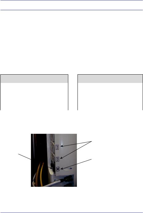
The auxiliary sockets are numbered 1 through 4, top to bottom and are rated as in the following tables. If the machine has the switching sockets option, sockets 3 and 4 will switch On and Off when the Main On/Off (Figure 1, Key O) is switched On and Off, rather than with the Mains On/Off switch (Figure 2).
230V
Socket |
Outlet |
Breaker |
Fuse |
Rating |
|||
|
|
|
|
1 |
2A |
3A |
5A |
|
|
|
|
2 - 4 |
1A |
2A |
3.15A |
|
|
|
|
1.4.5.1Electrical Labeling
Mains ON/OFF
switch
110V
Socket |
Outlet |
Breaker |
Fuse |
Rating |
|||
|
|
|
|
1 - 4 |
2A |
3A |
4A |
|
|
|
|
|
|
|
|
Switched outlet label
Isolation transformer label
Figure 2 - Electrical Labeling
27

Technical Description
1.4.6Supplies
O2, MED AIR, N2O pipeline Nominal pressure 400 kPa/58.0 psi, minimum 275 kPa/39.8 psi, maximum
482 kPa/69.9 psi
Auxiliary pneumatic outlets MED AIR or O2 - 400 kPa/58.0 psi at zero fl ow. 80 l/m max. fl ow
Auxiliary Oxygen Outlet |
0-15 lpm |
1.4.7 Environmental
Operating Temperature |
5ºC-40ºC (41ºF-104ºF) |
|
oxygen cell operates to specifi cation |
|
10ºC-40ºC (50ºF-104ºF) |
Storage Temperature |
-20oC-60ºC (-4ºF-140ºF) with oxygen |
|
cell removed |
|
0ºC-50ºC (32ºF-122ºF) with oxygen |
|
cell in place |
Humidity |
15-95% Non-condensing |
|
|
28

BleaseSirius
Anesthetic Machine
Chapter 2
Overview
29

Overview
30
 Loading...