


 Loading...
91369 Service Manual
070-1156-00 Rev. E

©2007 Spacelabs Medical, Inc.
All rights reserved. Contents of this publication may not be reproduced in any form without the written permission of Spacelabs Medical. Products of Spacelabs Medical are covered by U.S. and foreign patents and/or pending patents. Printed in U.S.A. Specifications and price change privileges are reserved.
Spacelabs Medical considers itself responsible for the effects on safety, reliability and performance of the equipment only if:
•assembly operations, re-adjustments, modifications or repairs are carried out by persons authorized by Spacelabs Medical, and
•the electrical installation of the relevant room complies with the requirements of the standard in force, and
•the equipment is used in accordance with the operations manual.
Spacelabs Medical will make available, on request, such circuit diagrams, component part lists, descriptions, calibration instructions or other information which will assist appropriately qualified technical personnel to repair those parts of the equipment which are classified by Spacelabs Medical as field repairable.
Spacelabs Medical is committed to providing comprehensive customer support beginning with your initial inquiry through purchase, training, and service for the life of your Spacelabs Medical equipment.
CORPORATE OFFICES
U.S.A.
Spacelabs Medical, Inc.
5150 220th Ave SE
Issaquah, WA 98029
Telephone: 425-657-7200
Telephone: 800-522-7025
Fax: 425-657-7212
Authorized EC Representative UNITED KINGDOM
Spacelabs Healthcare, Ltd.
Beech House, Chiltern Court
Asheridge Road, Chesham
Buckinghamshire HP5 2PX
Telephone: 44 (0) 1494 784422
Fax: 44 (0) 1494 794414
BirthNet, Clinical Browser, Data Shuttle, Flexport, Intesys, Mermaid, MOM, Multiview, PCIS, PCMS, PrintMaster, Quicknet, Sensorwatch, TRU-CAP, TRU-CUFF, TruLink, Ultralite, Ultraview, Ultraview Care Network, Ultraview Clinical Messenger, Ultraview Digital Telemetry, Ultraview SL, Uni-Pouch, UCW, Varitrend and WinDNA are trademarks of Spacelabs Medical, Inc.
Other brands and product names are trademarks of their respective owners.
Caution:
Rx Only
!
US Federal law restricts the devices documented herein to sale by, or on the order of, a physician.
Before use, carefully read the instructions, including all warnings and cautions.

Table of Contents
Contents |
Page |
Introduction
Overview. . . . . . . . . . . . . . . . . . . . . . . . . . . . . . . . . . . . . . . . . . . . . . . . . . . . . . . . . . . . . . . . . . . . . . . . . . . . . . . . . 1-1
Physical Dimensions. . . . . . . . . . . . . . . . . . . . . . . . . . . . . . . . . . . . . . . . . . . . . . . . . . . . . . . . . . . . . . . . . . . . . . . . 1-2
Electrical Specifications . . . . . . . . . . . . . . . . . . . . . . . . . . . . . . . . . . . . . . . . . . . . . . . . . . . . . . . . . . . . . . . . . . . . . 1-2
Environmental Requirements . . . . . . . . . . . . . . . . . . . . . . . . . . . . . . . . . . . . . . . . . . . . . . . . . . . . . . . . . . . . . . . . . 1-3
Regulatory Approvals . . . . . . . . . . . . . . . . . . . . . . . . . . . . . . . . . . . . . . . . . . . . . . . . . . . . . . . . . . . . . . . . . . . . . . . 1-3
Monitor Options . . . . . . . . . . . . . . . . . . . . . . . . . . . . . . . . . . . . . . . . . . . . . . . . . . . . . . . . . . . . . . . . . . . . . . . . . . . 1-3
Display . . . . . . . . . . . . . . . . . . . . . . . . . . . . . . . . . . . . . . . . . . . . . . . . . . . . . . . . . . . . . . . . . . . . . . . . . . . . . . . . . . 1-4
Setup
Unpacking the Monitor . . . . . . . . . . . . . . . . . . . . . . . . . . . . . . . . . . . . . . . . . . . . . . . . . . . . . . . . . . . . . . . . . . . . . . 2-1
Assembling the Monitor . . . . . . . . . . . . . . . . . . . . . . . . . . . . . . . . . . . . . . . . . . . . . . . . . . . . . . . . . . . . . . . . . . . . . 2-2
Connections . . . . . . . . . . . . . . . . . . . . . . . . . . . . . . . . . . . . . . . . . . . . . . . . . . . . . . . . . . . . . . . . . . . . . . . . . . . . . . 2-4
Cabling . . . . . . . . . . . . . . . . . . . . . . . . . . . . . . . . . . . . . . . . . . . . . . . . . . . . . . . . . . . . . . . . . . . . . . . . . . . . . . . . . . 2-7
SDLC Bus Termination. . . . . . . . . . . . . . . . . . . . . . . . . . . . . . . . . . . . . . . . . . . . . . . . . . . . . . . . . . . . . . . . . . . . . . 2-8
Network Installation . . . . . . . . . . . . . . . . . . . . . . . . . . . . . . . . . . . . . . . . . . . . . . . . . . . . . . . . . . . . . . . . . . . . . . . 2-11
Power-ON Test. . . . . . . . . . . . . . . . . . . . . . . . . . . . . . . . . . . . . . . . . . . . . . . . . . . . . . . . . . . . . . . . . . . . . . . . . . . 2-12
Configuring the Monitor . . . . . . . . . . . . . . . . . . . . . . . . . . . . . . . . . . . . . . . . . . . . . . . . . . . . . . . . . . . . . . . . . . . . 2-13
Theory
Overview. . . . . . . . . . . . . . . . . . . . . . . . . . . . . . . . . . . . . . . . . . . . . . . . . . . . . . . . . . . . . . . . . . . . . . . . . . . . . . . . . 3-1
Major System Components . . . . . . . . . . . . . . . . . . . . . . . . . . . . . . . . . . . . . . . . . . . . . . . . . . . . . . . . . . . . . . . . . . 3-2
Printed Circuit Board Assemblies (PCBAs) . . . . . . . . . . . . . . . . . . . . . . . . . . . . . . . . . . . . . . . . . . . . . . . . . . . . . . 3-5
Interconnect and Connector PCBAs. . . . . . . . . . . . . . . . . . . . . . . . . . . . . . . . . . . . . . . . . . . . . . . . . . . . . . . . . . . 3-15
Bezel Assembly . . . . . . . . . . . . . . . . . . . . . . . . . . . . . . . . . . . . . . . . . . . . . . . . . . . . . . . . . . . . . . . . . . . . . . . . . . 3-16
Boot Sequence Overview . . . . . . . . . . . . . . . . . . . . . . . . . . . . . . . . . . . . . . . . . . . . . . . . . . . . . . . . . . . . . . . . . . . 3-18
Normal Operation Overview . . . . . . . . . . . . . . . . . . . . . . . . . . . . . . . . . . . . . . . . . . . . . . . . . . . . . . . . . . . . . . . . . 3-18
Display . . . . . . . . . . . . . . . . . . . . . . . . . . . . . . . . . . . . . . . . . . . . . . . . . . . . . . . . . . . . . . . . . . . . . . . . . . . . . . . . . 3-19
Parameter Modules . . . . . . . . . . . . . . . . . . . . . . . . . . . . . . . . . . . . . . . . . . . . . . . . . . . . . . . . . . . . . . . . . . . . . . . 3-21
CPU PCBA Connectors . . . . . . . . . . . . . . . . . . . . . . . . . . . . . . . . . . . . . . . . . . . . . . . . . . . . . . . . . . . . . . . . . . . . 3-21
CPU PCBA Jumpers. . . . . . . . . . . . . . . . . . . . . . . . . . . . . . . . . . . . . . . . . . . . . . . . . . . . . . . . . . . . . . . . . . . . . . . 3-22
I/O PCBA Connectors . . . . . . . . . . . . . . . . . . . . . . . . . . . . . . . . . . . . . . . . . . . . . . . . . . . . . . . . . . . . . . . . . . . . . 3-22
Interconnect PCBA Connectors . . . . . . . . . . . . . . . . . . . . . . . . . . . . . . . . . . . . . . . . . . . . . . . . . . . . . . . . . . . . . . 3-23
Maintenance
Overview. . . . . . . . . . . . . . . . . . . . . . . . . . . . . . . . . . . . . . . . . . . . . . . . . . . . . . . . . . . . . . . . . . . . . . . . . . . . . . . . . 4-1
Mechanical Inspection . . . . . . . . . . . . . . . . . . . . . . . . . . . . . . . . . . . . . . . . . . . . . . . . . . . . . . . . . . . . . . . . . . . . . . 4-2
Electrical Safety Testing . . . . . . . . . . . . . . . . . . . . . . . . . . . . . . . . . . . . . . . . . . . . . . . . . . . . . . . . . . . . . . . . . . . . . 4-2
Preventive Maintenance . . . . . . . . . . . . . . . . . . . . . . . . . . . . . . . . . . . . . . . . . . . . . . . . . . . . . . . . . . . . . . . . . . . . . 4-4
Functional Tests . . . . . . . . . . . . . . . . . . . . . . . . . . . . . . . . . . . . . . . . . . . . . . . . . . . . . . . . . . . . . . . . . . . . . . . . . . . 4-5
Assembly/Disassembly Procedures . . . . . . . . . . . . . . . . . . . . . . . . . . . . . . . . . . . . . . . . . . . . . . . . . . . . . . . . . . . . 4-6
Cleaning . . . . . . . . . . . . . . . . . . . . . . . . . . . . . . . . . . . . . . . . . . . . . . . . . . . . . . . . . . . . . . . . . . . . . . . . . . . . . . . . 4-24
Troubleshooting
Overview. . . . . . . . . . . . . . . . . . . . . . . . . . . . . . . . . . . . . . . . . . . . . . . . . . . . . . . . . . . . . . . . . . . . . . . . . . . . . . . . . 5-1
System Startup . . . . . . . . . . . . . . . . . . . . . . . . . . . . . . . . . . . . . . . . . . . . . . . . . . . . . . . . . . . . . . . . . . . . . . . . . . . . 5-2
Boot Menu . . . . . . . . . . . . . . . . . . . . . . . . . . . . . . . . . . . . . . . . . . . . . . . . . . . . . . . . . . . . . . . . . . . . . . . . . . . . . . . 5-3
Power-ON Diagnostics . . . . . . . . . . . . . . . . . . . . . . . . . . . . . . . . . . . . . . . . . . . . . . . . . . . . . . . . . . . . . . . . . . . . . . 5-6
Extended Diagnostics. . . . . . . . . . . . . . . . . . . . . . . . . . . . . . . . . . . . . . . . . . . . . . . . . . . . . . . . . . . . . . . . . . . . . . . 5-6
Diagnostic Menus . . . . . . . . . . . . . . . . . . . . . . . . . . . . . . . . . . . . . . . . . . . . . . . . . . . . . . . . . . . . . . . . . . . . . . . . . . 5-7
91369 Service Manual |
i |

Table of Contents
Error Log. . . . . . . . . . . . . . . . . . . . . . . . . . . . . . . . . . . . . . . . . . . . . . . . . . . . . . . . . . . . . . . . . . . . . . . . . . . . . . . . 5-10
Diagnostics Failure Messages and Error Codes . . . . . . . . . . . . . . . . . . . . . . . . . . . . . . . . . . . . . . . . . . . . . . . . . 5-11
System Troubleshooting. . . . . . . . . . . . . . . . . . . . . . . . . . . . . . . . . . . . . . . . . . . . . . . . . . . . . . . . . . . . . . . . . . . . 5-13
Parts
Overview. . . . . . . . . . . . . . . . . . . . . . . . . . . . . . . . . . . . . . . . . . . . . . . . . . . . . . . . . . . . . . . . . . . . . . . . . . . . . . . . . 6-1
Parts List. . . . . . . . . . . . . . . . . . . . . . . . . . . . . . . . . . . . . . . . . . . . . . . . . . . . . . . . . . . . . . . . . . . . . . . . . . . . . . . . . 6-1
Assembly Drawings and Schematics . . . . . . . . . . . . . . . . . . . . . . . . . . . . . . . . . . . . . . . . . . . . . . . . . . . . . . . . . . . 6-4
Directory of Keys
BIOMED Directory of Keys . . . . . . . . . . . . . . . . . . . . . . . . . . . . . . . . . . . . . . . . . . . . . . . . . . . . . . . . . . . . . . . . . . . 7-1
Glossary
Appendix A — Electromagnetic Compatibility
Electromagnetic Emissions. . . . . . . . . . . . . . . . . . . . . . . . . . . . . . . . . . . . . . . . . . . . . . . . . . . . . . . . . . . . . . . . . . . A-1
Electromagnetic Immunity . . . . . . . . . . . . . . . . . . . . . . . . . . . . . . . . . . . . . . . . . . . . . . . . . . . . . . . . . . . . . . . . . . . A-2
Separation Distances . . . . . . . . . . . . . . . . . . . . . . . . . . . . . . . . . . . . . . . . . . . . . . . . . . . . . . . . . . . . . . . . . . . . . . . A-3
Appendix B — Symbols 1
91369 Service Manual |
ii |

Introduction
Contents
Overview. . . . . . . . . . . . . . . . . . . . . . . . . . . . . . . . . . . . . . . . . . . . . . . . . . . . . . . . . . . . . . . . . . . . . . . . . . . . . . .1
Physical Dimensions. . . . . . . . . . . . . . . . . . . . . . . . . . . . . . . . . . . . . . . . . . . . . . . . . . . . . . . . . . . . . . . . . . . . . .2
Electrical Specifications . . . . . . . . . . . . . . . . . . . . . . . . . . . . . . . . . . . . . . . . . . . . . . . . . . . . . . . . . . . . . . . . . . .2
Environmental Requirements . . . . . . . . . . . . . . . . . . . . . . . . . . . . . . . . . . . . . . . . . . . . . . . . . . . . . . . . . . . . . . .3
Regulatory Approvals . . . . . . . . . . . . . . . . . . . . . . . . . . . . . . . . . . . . . . . . . . . . . . . . . . . . . . . . . . . . . . . . . . . . .3
Monitor Options . . . . . . . . . . . . . . . . . . . . . . . . . . . . . . . . . . . . . . . . . . . . . . . . . . . . . . . . . . . . . . . . . . . . . . . . .3
Overview
Spacelabs Medical’s products are designed and manufactured under good manufacturing practices and in compliance with all applicable regulatory requirements. To ensure proper operation in accordance with these guidelines, this product must be maintained by trained technicians, using Spacelabs Medical authorized replacement parts.
Warnings, cautions, and notes are used throughout this manual. They are identified by the formats shown below. Be sure to read all warnings, cautions, and notes included in each section of this manual.
Warning:
Alerts the user to potentially serious outcomes (death, injury, or serious adverse events) to the patient or user.
Caution:
Alerts the user to actions to be taken to avoid non-serious injury to the patient or user, or to adverse effects to the device.
Note:
Failure to observe notifications may result in unexpected outcomes.
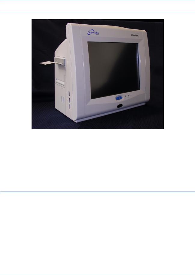
The 91369 monitor is a lightweight, portable monitor designed for use as a compact bedside monitor or as a battery-operated transport monitor. The monitor features a five-wire, resistive touchscreen and can be operated on either AC mains or battery power.
The single-high module slot on the right side of the monitor accepts all single-high modules, including the 90496 Ultraview® Command module and 91496 Ultraview SL™ Command module, to permit the monitoring of parameters such as electrocardiography (ECG), pulse oximetry (SpO2), temperature, and invasive pressure.
91369 Service Manual |
1-1 |
Introduction
|
Figure 1-1: 91369 monitor |
|
|
|
|
|
|
|
Physical Dimensions |
|
|
Assembled weight |
10.0 pounds (4.6 kg) |
|
Dimensions |
8.3 (H) × 11.7 (W) × 6.2 (D) inches |
|
(21.1 × 29.7 × 15.8 cm) |
||
|
Electrical Specifications
Designed for continuous operation. Requires outlet with ground (Protective Earth) conductor. Designated Class I by applicable electrical safety standards.
AC Line Requirements
AC input voltage range |
100 to 240 VAC |
AC input current |
1.0 A |
AC input frequency range |
50 – 60 Hz |
91369 Service Manual |
1-2 |

|
Introduction |
|
|
|
|
|
|
Environmental Requirements |
|
Operating temperature |
0° to 50° C |
Humidity (operating) |
10% to 95% relative humidity, non-condensing |
Regulatory Approvals
C |
® |
0123 |
US |
|
CSA certified. Meets IEC60601-1, UL60601-1, and CSA C22.2 No. 601.1 for electrical safety. CE marked in accordance with the Medical Device Directive 93/42/EEC.
Monitor Options
The following options are available:
|
Table 1: 91369 Monitor Options |
|
|
|
|
Option |
Definition |
|
|
|
|
D |
Perioperative |
|
|
|
|
J |
Dual-channel internal recorder (Polish,Czech, Portuguese |
|
language support only) |
||
|
||
|
|
|
N |
Vital Signs Calculations |
|
|
|
|
O |
Drug Dose Calculations |
|
|
|
|
Q |
Data Shuttle® |
|
R |
Patient Data Logger (PDL) |
|
|
|
|
U |
Dual-channel internal recorder (no Polish language support) |
|
|
|
|
Z |
Wireless networking |
|
|
|
|
04 |
Four waveform zones |
|
|
|
|
06 |
Six waveform zones |
|
|
|
91369 Service Manual |
1-3 |

Introduction
Display
The video input of the display conforms with the Video Electronics Standards Association (VESA) display resolution of 1024 × 768 pixels. The monitor does not support an external touchscreen.
|
Vertical |
Horizontal |
|
|
|
Rate |
64 Hz |
51.584 Hz |
|
|
|
Front porch |
58 μs |
0.350 μs |
|
|
|
Sync width |
116 μs |
1.985 μs |
|
|
|
Back porch |
562 μs |
2.101 μs |
|
|
|
Blank |
737 μs |
4.435 μs |
|
|
|
Video clock rate |
68.5 MHz |
51.584 KHz |
|
|
|
91369 Service Manual |
1-4 |

Setup
Contents
Unpacking the Monitor . . . . . . . . . . . . . . . . . . . . . . . . . . . . . . . . . . . . . . . . . . . . . . . . . . . . . . . . . . . . . . . . . . . .1
Assembling the Monitor . . . . . . . . . . . . . . . . . . . . . . . . . . . . . . . . . . . . . . . . . . . . . . . . . . . . . . . . . . . . . . . . . . .2
Connections . . . . . . . . . . . . . . . . . . . . . . . . . . . . . . . . . . . . . . . . . . . . . . . . . . . . . . . . . . . . . . . . . . . . . . . . . . . .4
Cabling . . . . . . . . . . . . . . . . . . . . . . . . . . . . . . . . . . . . . . . . . . . . . . . . . . . . . . . . . . . . . . . . . . . . . . . . . . . . . . . .7
Network Installation . . . . . . . . . . . . . . . . . . . . . . . . . . . . . . . . . . . . . . . . . . . . . . . . . . . . . . . . . . . . . . . . . . . . .11
Power-ON Test . . . . . . . . . . . . . . . . . . . . . . . . . . . . . . . . . . . . . . . . . . . . . . . . . . . . . . . . . . . . . . . . . . . . . . . . .12
Configuring the Monitor . . . . . . . . . . . . . . . . . . . . . . . . . . . . . . . . . . . . . . . . . . . . . . . . . . . . . . . . . . . . . . . . . .13
Unpacking the Monitor
The 91369 monitor, one or two batteries, external AC power supply, and any optional accessories are all packaged and shipped in a single box. Keep at least one shipping box and its packing materials for reshipping, if the monitor should ever require factory service.
Caution:
Observe precautions for handling electrostatic-sensitive devices!
Note:
•Never touch electrostatic-sensitive electronic components without following proper anti-static procedures, including the use of an ESD wrist band and mat. An electrostatic discharge from your fingers can permanently damage electronic components and cause latent failures.
•All static-sensitive electronic components are packaged in static-shielding bags. Retain the bag for repackaging the component should you need to store it or return it to Spacelabs Medical for any reason.
The monitor is typically shipped as follows:
Top Assembly — Contains the main enclosure with installed CPU, power supply, and I/O PCBAs.
Accessories — Contains the external DC power supply, U.S. power cord, international power cords (if applicable), and any cable assemblies ordered.
Before installing the monitor:
Note:
When removing items from the shipping containers, ensure that you remove ALL components from each container.
1Unpack the received equipment.
2Unpack the mounting hardware.
3Conduct an equipment audit.
91369 Service Manual |
2-1 |

Setup
Upon receiving the equipment, complete a detailed inventory to verify that the equipment you received matches your order. This inventory must include serial numbers, model numbers, and all options and cables received. Carefully inspect these items for shipping damage. If any damage is evident, immediately notify the freight company and Spacelabs Medical.
Assembling the Monitor
Power and Battery Status
The three LEDs on the monitor indicate whether the monitor is connected to the AC mains power and the status of any installed batteries. Battery status conditions are indicated as described in the following sections.
|
|
|
|
Battery |
|
status |
|
|
|
|
|
||
Power ON/OFF |
Power LED |
|
||||
switch |
|
|
LEDs |
|||
Figure 2-1: Battery status information
Power LED
The power LED is located immediately to the right of the power ON/OFF switch. This LED is lit whenever the monitor is connected to AC mains power via its power supply, and is not lit if the monitor is not connected to the AC mains power.
Battery Status LEDs
These LEDs are only active while the unit is connected to AC mains power.
Unlit LED
A battery LED that is neither solid ON nor flashing indicates a battery is not present.
Solid Green LED
A solid green battery LED indicates that the battery is fully charged. Only a charging cycle or a faulty battery will cause the green LED to flash, and these conditions only occur when a battery is installed in the monitor.
91369 Service Manual |
2-2 |
Setup
Flashing Green LED — Battery Charging
A flashing green battery LED indicates an installed battery is being charged and the monitor is not completely ready to be used in transport mode. This LED flashes in a constant pattern with no delays with the monitor powered ON or OFF. The flashing is different than the battery fault detection flash.
Note:
The green LED stops flashing and stays ON when the charging cycle is complete.
Intermittent Flashing Green LED — Battery Fault Detected
An intermittent flashing green LED indicates that this battery will not hold a charge, or is taking too long to charge. The intermittent signal is a repeating pattern of a solid green LED for one second and a flashing LED for one second. An error message is also added to the error log for review by your system administrator.
To determine whether a battery is faulty, power the monitor ON using the front-panel switch and observe the message displayed along the bottom of the monitor screen. Replace a faulty battery with the same battery type.
Installing/Replacing Batteries
NiMH batteries are used in the monitor. Refer to Figure 2-2 to install one or two batteries.
Figure 2-2: Monitor battery installation
91369 Service Manual |
2-3 |

Setup
While the monitor is operational, a single battery can be exchanged under any of the following conditions without a loss of patient data:
•The monitor is being powered by the external power supply.
•The monitor is operating on two batteries, and one charged battery remains connected at all times during the exchange.
Warning:
Batteries exposed to short circuit, high temperature, or fire may leak, vent, or explode.
Caution:
Follow the manufacturer’s recommended handling procedure. Collect and transport batteries in a manner that prevents short circuit, compacting, mutilation, or any other abuse that would compromise the physical integrity.
Connections
Refer to Figure 2-3 for available connections on the monitor’s rear panel. Refer to Figure 2-4 for available connections on the monitor’s side panel.
Rear Panel
Equipotential ground post
External power supply input
SDLC port
Alarm relay output
Video output
Serial port
|
|
Figure 2-3: Rear panel connections
91369 Service Manual |
2-4 |

Setup
Table 1: Rear Panel Cables
Rear Panel |
Description |
Part Number |
|
Connection |
|||
|
|
||
|
|
|
|
|
Cable, Serial I/O (RS-232) |
As required |
|
|
|
|
|
|
Cable, Video, DB15HD Male to DB15HD Male, |
012-0593-00 |
|
1.8 m (6 feet) |
|||
|
|
||
|
|
|
|
|
Cable, SDLC |
As required |
|
|
|
|
|
|
Cable, Monitor to Module Housing, 0.61 m (2 feet) |
012-0532-02 |
|
|
|
|
|
|
Cable, Monitor to Module Housing, 1.22 m (4 feet) |
012-0532-04 |
|
|
|
|
|
|
Cable, Monitor to Module Housing, 2.44 m (8 feet) |
012-0532-08 |
|
|
|
|
|
|
Cable, Monitor to Module Housing, 3.05 m (10 feet) |
012-0532-10 |
|
|
|
|
Caution:
For continued electromagnetic interference (EMI) radiation compliance, use only cables that have been tested and approved by Spacelabs Medical. Refer to Table 2 on page 6-3 for all cable part numbers.
91369 Service Manual |
2-5 |
Setup
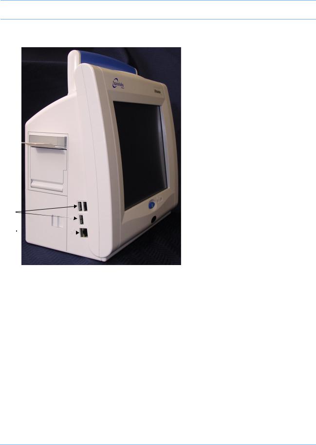
Side Panel
|
USB ports |
|
10/100BaseT network |
|
connection |

Figure 2-4: Side panel connections
Note:
The USB ports are to be used for Spacelabs-approved devices only (Symbol/Metrologic barcode scanner and Microsoft USB keyboard/mouse devices).
Table 2: Side Panel Cables
Side Panel |
Description |
Part Number |
|
Connection |
|||
|
|
||
|
|
|
|
|
Cable, Ethernet, 10/100BaseT, 0.94 m (3 feet) |
175-0951-00 |
|
|
|
|
|
|
Cable, Ethernet, 10/100BaseT, 1.8 m (6 feet) |
175-0951-01 |
|
|
|
|
|
|
Cable, Ethernet, 10/100BaseT, 3.7 m (12 feet) |
175-0951-02 |
|
|
|
|
|
|
Cable, Ethernet, 10/100BaseT, 6.1 m (20 feet) |
175-0951-03 |
|
|
|
|
91369 Service Manual |
2-6 |

Setup
Cabling
Maximum Cable Lengths
The following cables are limited to the indicated maximum length:
•SDLC Cable — 12.2 m (40 feet) maximum (total length from the monitor to the last device on the bus). For longer SDLC cable runs, contact a Spacelabs Medical Field Service Engineer.
•Video Cable — 30.5 m (100 feet) maximum (total length from the monitor to the last display).
•Ethernet cable (10/100BaseT) — 100 m (328 feet) maximum.
SDLC External Devices
External devices (for example, Flexport® system interfaces) can be connected to the SDLC bus. (In this context, the term “external” means connected to the SDLC bus by cable via an external connector. This is in contrast to modules, which are connected by inserting them into a module housing.)
If no supplementary module housings are present (in addition to the module slot integral to the monitor itself), then external devices are connected directly to the SDLC connector of the monitor.
If one or more supplementary module housings are present, Flexport devices are connected to connector J2 on one of the 90499 or 90491 supplementary module housings, or J3 on model 90485. Refer to the Module Housings and Power Supplies Service Manual (P/N 070-0680-xx).
If multiple module housings are present, external devices must be connected to the last module housing in the daisy-chain; that is, the housing electrically farthest from the monitor on the SDLC bus. Even though multiple connectors may be available, only the SDLC connector on the most distal module housing can be used for connecting external devices. Do not use more than a single Flexport connector, regardless of how many module housings are present.
If multiple Flexport interfaces are to be installed, they must be daisy-chained using the T-cable supplied with those devices. Up to three Flexport interfaces may be connected in this way.
Warning:
Unreliable system operation will occur if the SDLC bus is not correctly terminated or the maximum cable length is exceeded. Flexport interfaces must be attached to the most distal module housing on the SDLC bus.
SDLC Cable Interconnection
To ensure electromagnetic interference (EMI) compliance, the appropriate Spacelabs Medical 9-pin connector must be used. Refer to the Module Housings and Power Supplies Service Manual
(P/N 070-0680-xx).
91369 Service Manual |
2-7 |

Setup
SDLC Bus Termination
The SDLC bus must be properly terminated for correct operation. If no external devices (for example, Flexports or multigas analyzers) are connected, proper termination of the SDLC bus is accomplished automatically. If external devices are connected, the switch on the module housing farthest from the monitor must be set to the terminated ( ) position. All others must be set to the non-terminated (
 ) position. The SDLC clock and data signals are switched by the terminator switches and are not present “downstream” of any switch set to the
  position.
Non-terminated Terminated
Figure 2-5: Terminator switch settings
Because bus termination is handled by setting the switches appropriately, an external terminator is only required when external devices are connected.
If external devices are connected, an external cable terminator is required to terminate the SDLC bus. This must be installed at the end of the SDLC bus (following the last external device). In this case, all module housings must have their switches in the  position.
Note:
Flexports require a powered Flexport cable (P/N 012-0555-00) when used with the 90491/90499 module housing or 91369 monitor. SDLC data is only passed along to the external device(s) when the terminator switch (SW2) is in the  position.
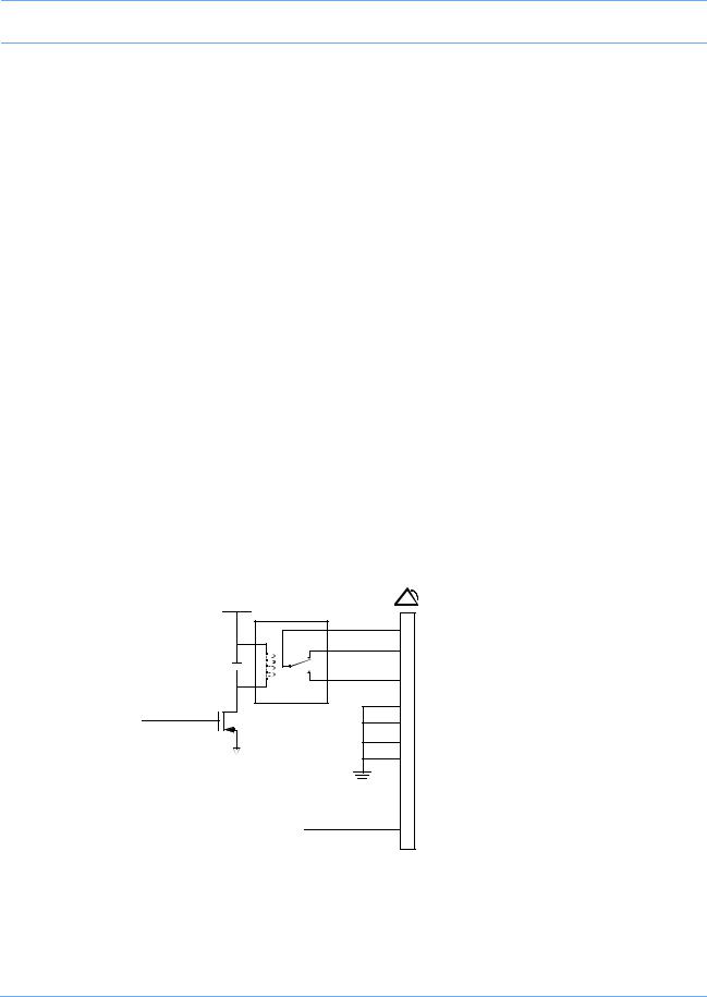
Alarm Relay
Alarm output signals are available at the Nurse Alert (
 ) connector instantaneously when an alarm occurs. Table 3 describes the connector pinouts for remote alarms. Figure 2-6, Figure 2-7, and Figure 2-8 illustrate the circuits for each alarm function.
External Alarm Pinout
Alarm connector pinouts are as follows:
Table 3: Connector Pinouts
Pin |
Alarm Circuit |
Meaning |
|
|
|
1 |
|
Common |
|
|
|
2 |
Alarm 0 (high priority) |
Normally Closed |
|
|
|
3 |
|
Normally Open |
|
|
|
4 |
|
GND |
|
|
|
91369 Service Manual |
2-8 |
Setup
Table 3: Connector Pinouts (continued)
Pin |
Alarm Circuit |
Meaning |
|
|
|
5 |
|
Normally Closed |
|
|
|
6 |
Alarm 1 (medium priority) |
Normally Open |
|
|
|
7 |
|
Common |
|
|
|
8 |
|
GND |
|
|
|
9 |
|
+12 V, 140 mA |
|
|
|
10 |
|
GND |
|
|
|
11 |
|
GND |
|
|
|
12 |
|
Normally Open |
|
|
|
13 |
Alarm 2 (low priority) |
Common |
|
|
|
14 |
|
Normally Closed |
|
|
|
Warning:
For operational safety and reliability, the following relay contact ratings MUST NOT BE EXCEEDED:
•Current = 250 ma
•Voltage = 28 V AC/DC
|
+5 V |
|
|
|
common 1 |
Relay maximum ratings: |
|
|
NC |
2 |
28 V AC/DC |
|
|
0.25 A |
|
|
NO |
|
|
|
3 |
|
|
|
relay |
|
|
|
4 |
GND |
|
ALMON |
|
||
|
8 |
GND |
|
|
|
||
|
|
10 |
GND |
|
|
11 |
GND |
+12 V |
9 |
140 mA |
|
Figure 2-6: Alarm 0 (high priority) relay schematic
91369 Service Manual |
2-9 |

Setup
|
+5 V |
|
|
|
common 7 |
Relay maximum ratings: |
|
|
NC |
5 |
28 V AC/DC |
|
|
0.25 A |
|
|
NO |
|
|
|
6 |
|
|
|
relay |
|
|
|
4 |
GND |
|
ALMON |
|
||
|
8 |
GND |
|
|
|
||
|
|
10 |
GND |
|
|
11 |
GND |
|
+12 V |
9 |
140 mA |
|
|
||
Figure 2-7: Alarm 1 (medium priority) relay schematic |
|||
|
+5 V |
|
|
|
common 13 |
Relay maximum ratings: |
|
|
NC |
14 |
28 V AC/DC |
|
|
0.25 A |
|
|
NO |
|
|
|
12 |
|
|
|
relay |
|
|
|
4 |
GND |
|
ALMON |
|
||
|
8 |
GND |
|
|
|
||
|
|
10 |
GND |
|
|
11 |
GND |
|
+12 V |
9 |
140 mA |
|
|
||
Figure 2-8: Alarm 2 (low priority) relay schematic
91369 Service Manual |
2-10 |
Setup
Network Installation
A typical network consists of bedside and central monitors and an optional clinical information system (Figure 2-9).
94263
Flat-panel display
|
|
|
|
|
|
|
|
|
|
|
|
|
|
|
|
|
|
94260-19 |
|
|
|
|
|
|
|
|
M |
|
|||
|
|
|
|
|
|
|
|
|
|
o |
|
|
|
||
|
|
Flat-panel display |
|
|
|
|
|
|
|
|
|
||||
|
|
|
|
91387-27 |
|
|
|
d |
|
|
|
||||
|
|
|
|
|
|
|
|
|
|
|
|
|
|||
|
|
|
|
|
|
|
Bedside #n |
|
|
|
u |
|
|||
|
|
|
|
|
|
|
|
|
|
|
|||||
|
|
|
|
|
|
|
|
|
|
|
|
l |
|
||
|
|
|
|
|
|
|
|
|
|
|
|
||||
|
|
|
|
|
|
|
|
|
|
|
|
e |
|
||
|
|
|
|
|
|
|
|
|
|
|
|
||||
91387-38 |
|
|
|
|
|
|
|
|
s |
|
|||||
|
|
|
|
|
|
|
|
||||||||
|
|
|
|
|
|
|
|
|
|
|
|
||||
|
|
Central #n |
|
|
|
|
|
|
|
|
|
|
|
|
|
|
|
|
|
|
|
|
|
|
|
|
|
|
|
||
|
|
|
|
|
|
|
|
|
|
|
|
|
|
|
Clinical |
|
|
|
|
|
|
|
|
Ethernet Network |
|
|
|
Information |
|||
|
|
|
|
|
|
|
|
|
|
|
|
|
|
|
System |
|
|
|
|
|
|
|
|
|
|
|
|
|
|
|
|
|
|
|
|
|
|
|
|
|
|
|
|
|
|
|
|
|
|
|
|
|
|
|
|
|
|
|
|
|
|
|
|
91369 Bedside #n
Module
Figure 2-9: Typical network configuration
Warning:
Ensure that the Ethernet wall plate and the shield of the Ethernet connecting cable are bonded to the hospital grounding system.
Ethernet Network Connection
Caution:
•Only qualified personnel should attempt to connect a monitor to an Ethernet LAN the first time.
•Do not connect the monitor to an Ethernet local area network (LAN) prior to configuring the following settings. The monitor must be properly configured for LAN access before you operate the monitor. If you fail to correctly configure the monitor, you may interrupt other units also using the LAN.
Note:
Detailed installation instructions for the physical Ethernet LAN are beyond the scope of this document.
91369 Service Manual |
2-11 |

Setup
To connect a monitor onto an existing Spacelabs Medical Ethernet LAN, complete the following steps:
1Install the monitor on a suitable table or shelf, ensuring that the air flow to the side air intake vents is unobstructed, or use a Spacelabs Medical mounting option.
2Ensure that the monitor is not connected to the LAN.
3Plug the power cord attached to the monitor’s DC power supply into a standard hospital-grade AC power supply.
4Power ON the monitor.
5Enter a unique MONITOR ID, BED NAME, and SUBNET for the monitor. Refer to Network Setup on page 2- 13 for more information.
6Attach the 10/100BaseT LAN transceiver cable into the RJ45 connector on the left side of the monitor ( in Figure 2-4 on page 2-6).
7Connect the other end of the Ethernet cable from the monitor to the nearest port.
8Configure the monitor’s other network settings as necessary to ensure proper communication on the network. Refer to Network Setup on page 2-13.
Ethernet Network Disconnection
To remove a monitor from the LAN, disconnect the network cable from the 10/100BaseT network connection ( in Figure 2-4 on page 2-6).
Power-ON Test
Each time the monitor is powered ON:
•Diagnostic information displays for approximately 10 seconds.
•The embedded alarm light cycles red and yellow. Some models may cycle red, yellow, and cyan.
•Monitor keys display on the right side of the screen.
The monitor is now ready for normal operation.
External Devices
If an external SDLC device, such as a Flexport interface, is to be installed, the 9-pin SDLC connector on the rear of the monitor or the module housing must be used. If multiple SDLC ports on module housings are available, only the SDLC port on the module housing farthest from the monitor can be used for external devices. Set the termination switch to non-terminated ( ) for all module housings and then terminate the external device.
91369 Service Manual |
2-12 |
Setup
Module Tests
To verify that the monitor functions correctly with parameter modules:
1Insert an ECG module without the patient cables connected. Verify that the ECG parameter key is displayed.
2Connect a patient simulator to the ECG input with a 5-lead patient cable, and set the simulator to a known rate.
•Verify that the heart rate and lead being monitored are displayed to the right of the ECG parameter key.
•Verify that the ECG waveform is displayed.
3Disconnect the patient cable. After 10 seconds, verify that the LEADS OFF message appears, the parameter key flashes, and an alarm tone sounds.
4Reconnect the patient cable and verify that the LEADS OFF message clears and the alarm stops.
5Connect a patient simulator to the invasive pressure inputs.
6Zero the pressures and verify that the numerics and waveforms are accurate.
7Verify that the key tone sounds each time a key is selected.
Configuring the Monitor
The Biomed Level menu displays when the biomed password (default is biomed) is entered into the Privileged Access window. Refer to Directory of Keys on page 7-1 for the Biomed Level menu structure.
Network Setup
Note:
The NETWORK SETUP key only displays on monitors that are configured for network operation.
Touch NETWORK SETUP to display the Monitor Setup - Network Configuration window. This window contains an on-screen keyboard and three tabs: TCP/IP, Monitor, and Printers. Proper network operation requires that each device on the network have a unique network address, monitor ID, and monitor name. If the wireless option has been installed on the monitor, three more tabs will be present: WLAN, Security, and
Advanced.
Editing Tab Fields
The fields within a tab on the Monitor Setup - Network Configuration window can be edited by selecting the field and entering new information using the on-screen or optional external keyboard.
When editing, adding, or deleting, press ENTER or TAB to cycle to the next input cell. Any changed or added items are stored in the monitor’s non-volatile memory when SAVE is selected. The description of each tab indicates when that change takes effect (for example, immediately or after a monitor reset occurs).
To edit text within a tab:
1Select an item from the list. -OR-
91369 Service Manual |
2-13 |
Setup
2Select an input cell’s text and type any combination of letters, characters, or spaces.
To add an item to a list:
• Select the input cell and type the new information.
To delete an item from a list:
1Select the item.
2Touch Del.
3Enter at least one space (an error message is displayed if no spaces are entered).
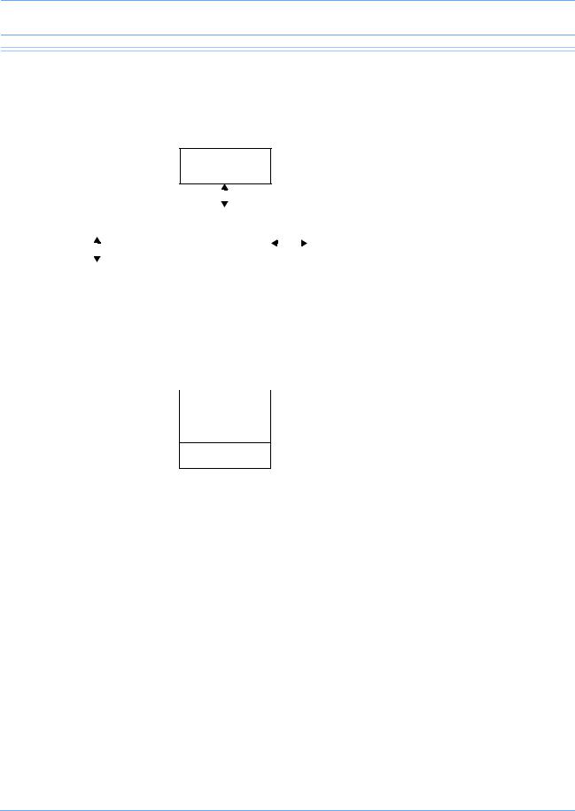
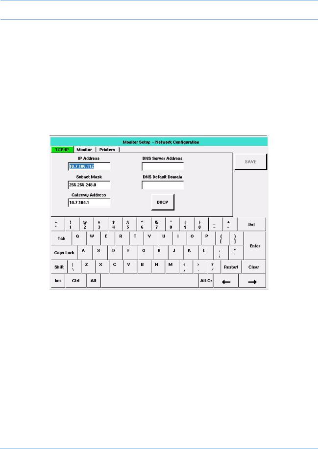
TCP/IP Tab
Figure 2-10: TCP/IP tab
The TCP/IP tab enables you to define the monitor’s attributes for networking.
IP Address — Enables you to specify the monitor’s IP address. The default is 164.90.254.10. Either a static IP address must be specified, or DHCP networking must be enabled.
Subnet Mask — Enables you to identify which parts of the IP address are to be used for TCP/IP subnet determination. The TCP/IP network’s subnet mask is not related to the Spacelabs Medical network’s subnet name. The standard and factory-default subnet mask is 255.255.255.0. Either a subnet mask must be specified, or DHCP networking must be enabled.
Gateway Address — Enables you to specify the IP address of the TCP/IP gateway (bridge or router) though which communication to other devices should flow. The default is blank.
DHCP — (Dynamic Host Configuration Protocol) Used to configure and enable DHCP network configuration. When DHCP is enabled, IP Address, Subnet Mask, and Gateway Address are automatically filled in. To use this service, a DHCP server must be available on the network to respond to DHCP requests.
91369 Service Manual |
2-14 |

Setup
Note:
•A DHCP lease is a TCP/IP configuration given out from the DHCP server that is valid for a period defined by the DHCP server or forever (no expiration).
•Monitors configured for DHCP operation request a lease from the DHCP server when they boot up or when their existing lease expires during operation. If the DHCP server is not present, the monitor checks the expiration time of the last DHCP lease obtained. If the lease is still valid, the monitor continues to use those values and operates normally. If the lease has expired, the monitor disables TCP/IP networking and displays a NETWORK SIGNAL LOST message to indicate that it is unable to communicate over the network. The monitor continues to request a DHCP lease until it receives one.
•If the monitor’s configured DECNET node ID is a duplicate on the network, the DHCP server can be confused. This may result in a duplicate or invalid DHCP lease and may prevent full network communication.
•The subnet mask must correctly correspond to the network size and type during operation. Monitors may not be able to fully communicate with each other if the DHCP server fails to set the network mask properly.
The DNS server address is in standard TCP/IP address form, while the DNS default domain is a string of ASCII characters. A DHCP server may also provide this information.
Editing this tab is performed as described in Editing Tab Fields on page 2-13. Tabbing order is IP Address >>
Subnet Mask >> Gateway Address >> DHCP >> DNS Server Address >> DNS Default Domain >> IP Address. Changes made to this tab’s settings take effect after a successful save and monitor reset.
Secondary Display — The Secondary Display field is only available if option -D, Perioperative, has been activated.
Select ENABLE on the TCP/IP tab to activate the primary monitor’s secondary display. When you enable the secondary display, the IP Address and Secondary Hostname fields become available and must contain a valid entry for the secondary monitor to operate. The IP Address and Secondary Hostname fields are exclusive to each other.
Enter a valid IP Address when your network is using static IP addresses. -OR-
Enter a valid Secondary DNS hostname when your network is using DHCP for network configuration. Changes made to the Secondary Display settings take effect after the changes have been saved.
91369 Service Manual |
2-15 |
Setup
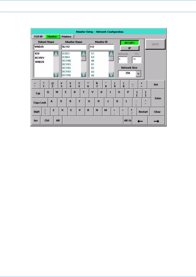
Monitor Tab
Figure 2-11: Monitor tab
The Monitor tab enables you to determine what monitor names, monitor (node) IDs, and subnet names are currently in use. The tab also enables you to enter settings for the monitoring network.
In Figure 2-11, the monitor’s current settings are displayed in each input cell. The scroll list below each input cell displays the remaining items that have been detected on the network. Items in the Subnet Name and Monitor Name lists are displayed in alphanumeric order. Items in the Monitor ID list are displayed in numeric order.
Brackets (< >) surround strings that consist solely of spaces. The separation within the brackets indicates the number of spaces within that string.
Editing is performed as described in Editing Tab Fields on page 2-13. The tabbing order is Subnet Name >>
Monitor Name >> Monitor ID >> DECNET/IP >> Network >> TTL >> Subnet Name. Network and TTL are skipped if unavailable. Changes made to this tab’s settings take effect after a successful save and monitor reset.
Subnet Name
The subnet name contains up to five characters (default is five blanks). Items in this scroll list are selectable.
Monitor Name and Monitor ID
The Monitor Name is the name given to each bedside and central monitor (does not apply to telemetry bed names) to help the users identify monitors on the network. The Monitor Name contains five characters (default is SL001).
The Monitor ID is the numeric ID assigned to a monitor. Each device on the network must have a unique Monitor ID. This can be any number from 1 to 1023, depending on the Network Size selected.
91369 Service Manual |
2-16 |

Setup
To prevent duplication of currently used monitor names and IDs, items in these lists are not selectable. The error checking procedure performed when SAVE is selected also specifically checks for duplications.
Note:
•Items in the Monitor Name and Monitor ID lists only display when the monitor is connected to the network.
•When entering a monitor name or ID, do not use a space between characters.
DECNET/IP
You can configure the monitor to operate using either Spacelabs DECNET or TCP/IP network protocols. If you are communicating with 903xx Spacelabs Medical monitors, you must select DECNET.
Network
The IP multicast group number of the monitor provides a filter to logically isolate one monitor from another on TCP/IP installations. Up to 32 network numbers are available (0 to 31) with 0 as the default.
Note:
•Monitors must use the same network number to communicate.
•This is unavailable if DECNET is selected.
TTL (Time to Live)
The allowed number of hops the IP packet can take across network devices. TTL values are 1 to 64, with 16 as the default.
Note:
TTL is unavailable if DECNET is selected.
Network Size
The network size allows configuration as:
64 — Monitor IDs from 1 to 64 are supported. No more than 64 total monitor devices can be on the network. Provides complete network compatibility with legacy Spacelabs Medical monitors.
250 — Monitor IDs from 1 to 250 are supported.
Note:
903xx monitors must have the Expanded Network option installed or they will not communicate correctly with devices with Monitor IDs above 64.
640 — Monitor IDs from 1 to 127 and from 512 to 1023 are supported with the following restrictions.
•All model 903xx Spacelabs Medical monitors must use monitor IDs 1 to 127, inclusive.
•All model 91xxx monitors must be configured with monitor IDs from 512 to 1023, inclusive.
1000 — Monitor IDs from 1 to 1023 are supported (compatible only with Spacelabs Medical 91xxx series monitors).
91369 Service Manual |
2-17 |
Setup
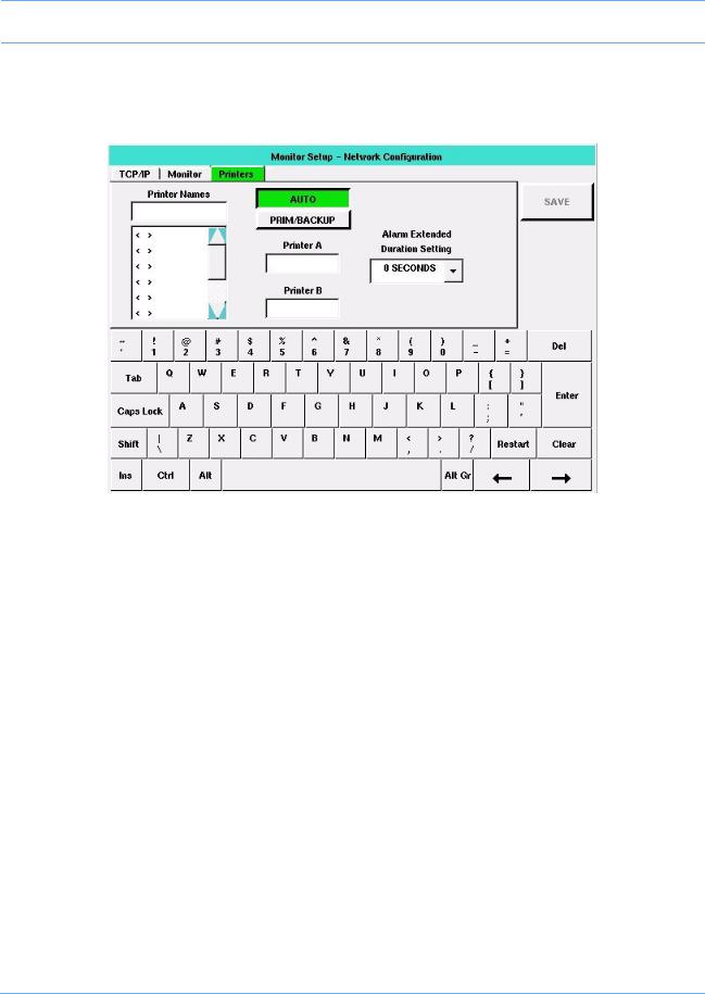
Printers Tab
The Printers tab enables you to display controls for defining and storing printer names, choosing rules for printer selection, and selecting one or two network printers.
Figure 2-12: Printers tab
Editing is performed as described in Editing Tab Fields on page 2-13. The tabbing order is AUTO / PRIM/ BACKUP >> Printer A (or Primary) >> Printer B (or Backup) >> Printer Names (refer to Figure 2-13 on page 2-19). Changes made to this tab’s settings take effect after a successful save and monitor reset.
Printer Names
The Printer Names list displays up to eight, selectable printer names previously stored in the monitor, in the order in which they were stored. To display a new or changed name in the list, select that printer name from the list. Printer names contain up to five characters (default is five blanks).
Note:
•Printer names are explicitly entered and may be duplicated. To clear a printer name from the list, select that name, touch Clear, touch Enter, and then touch SAVE.
•A local (SDLC) printer can be either a bedside printer or network printer, depending on the printer name selected in this list. A local printer is configured as a network printer if the local monitor’s name is selected. Otherwise, a local printer functions as the bedside printer.
91369 Service Manual |
2-18 |
Setup
AUTO / PRIM/BACKUP
The AUTO / PRIM/BACKUP key selects which set of printer selection rules the monitor uses for selecting network printers. It does not affect the monitor’s selection of whether a networked or non-networked printer is used. Any changes made to the printer selection mode using this key take effect immediately, regardless of monitor type. The default setting is AUTO, which selects the destination printer using the weight-based printer selection rules. (Refer to the Ultraview SL Operations Manual, P/N 070-1150-xx, located on CD-ROM
P/N 084-1101-xx for additional information).
When PRIM/BACKUP is selected, the monitor automatically selects the primary printer, unless that printer is unable to accept the recording. In that instance, the monitor then selects the backup printer. If the backup printer is also unable to accept the recording, the monitor displays an Unable to record message.
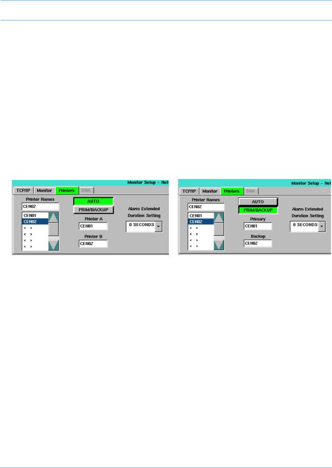
Printer Selection Fields
The default for the printer selection fields is blank (i.e., no printer selected). The labels above these fields vary, based on the current setting of the AUTO / PRIM/BACKUP key. If AUTO is selected, the labels are Printer A and Printer B. If PRIM/BACKUP is selected, the labels are Primary and Backup (Figure 2-13).
Figure 2-13: AUTO / PRIM/BACKUP selection differences
To define a printer name:
1Select a printer name from the Printer Names list.
2Select one of the two printer selection fields. The new value displays in the selected field.
WLAN Tab
This tab allows the operator to set basic wireless local area network (WLAN) related settings.
The WLAN tab only displays on monitors that are configured for wireless operation (option -Z). Monitors are configured for wireless operation by selecting the sysgen RADIO option. The RADIO ON/OFF keys and all other input cells and combo boxes illustrated in Figure 2-14 are not available for selection if the radio is not present.
Caution:
Do NOT power the radio ON until all network configuration has been completed. Powering the radio ON with the monitor set to the factory defaults could interfere with the wireless network.
91369 Service Manual |
2-19 |

Setup
Figure 2-14: WLAN tab
The tabbing order is RADIO ON/OFF >> SSID >> Region >> Outbound Parameters >> Wireless DHCP >> WLAN IP Address >> WLAN Subnet Mask >> Gateway Address >> RADIO ON/OFF. WLAN IP Address, WLAN Subnet Mask, and Gateway Address are not available in the tabbing order if Wireless DHCP is selected. Changes made to this tab’s settings take effect after a successful save and monitor reset.
RADIO ON/OFF (default = OFF)
The RADIO ON/OFF setting defaults to OFF when a radio is present. If this key is toggled to ON, and SAVE is selected without a valid region defined [refer to Region (default = blank) on page 2-22], an error box displays (the radio cannot be switched to ON if the Region setting is invalid). Select OK to remove the error box. The RADIO ON/OFF key automatically toggles back to OFF.
The radio will function only if this key is set to ON. Keys, input cells, select boxes, and combo boxes are enabled without regard to the setting of this key. However, WLAN communication only occurs if ON is selected.
Note:
Any change in the wireless tabs (except for the setting of the OUTBOUND PARAMETERS input cell) requires a monitor reset before the changes take effect.
To activate the radio-only functions, select ON.
Wireless DHCP (default = OFF)
The Wireless DHCP tab is similar in function to the DHCP key on the TCP/IP tab, but for wireless networks. When Wireless DHCP is selected, the monitor asks the wireless DHCP server for the following information:
•WLAN IP Address
•WLAN Subnet Mask
•Gateway Address
91369 Service Manual |
2-20 |

Setup
The affected input cells then display the values provided by the wireless DHCP server, rather than the values from the monitor’s non-volatile memory. These cells then become unavailable for selection, to prevent these values from being changed, until Wireless DHCP is de-selected.
If Wireless DHCP is selected, as in Figure 2-14 on page 2-20, DNS Server Address and DNS Default Domain values display, and the WLAN IP Address, Wireless Subnet Mask, and Gateway Address input cells are unavailable for selection.
When Wireless DHCP is not selected, the DNS Server Address and DNS Default Domain values disappear, and the WLAN IP Address, Wireless Subnet Mask, and Gateway Address input cells are available.
Table 4: Wireless DHCP Input Cells
|
|
Is this cell |
|
|
|
Can the wireless |
unavailable if the |
Can the cell be left |
|
Cell name |
DHCP server provide |
wireless DHCP |
||
blank? |
||||
|
this information? |
server provides the |
||
|
|
|||
|
|
information? |
|
|
|
|
|
|
|
WLAN IP Address |
Yes |
Yes |
No |
|
|
|
|
|
|
WLAN Subnet Mask |
Yes |
Yes |
No |
|
|
|
|
|
|
Gateway Address |
Yes |
Yes |
Yes |
|
|
|
|
|
Note:
Input cells that display wireless DHCP server-provided data may display values different than what is stored in the monitor’s non-volatile memory. DHCP server-provided values are not stored in non-volatile memory.
SSID (default = blank)
The SSID cell is used to define the WLAN Service Set Identifier (SSID) setting, which is the name used by acceptable access points (AP) for that WLAN. This field is up to 32 characters long, and it may contain any combination of case-sensitive characters. The default is blank.
Setting SSID and Security Mode
If enabled, WLAN card communication through the wireless network depends on the interaction between the WLAN card SSID setting (refer to SSID (default = blank)) and its security settings (refer to Security Tab on page 2-24).
91369 Service Manual |
2-21 |

Setup
The WLAN card SSID and security settings must match the settings of the intended access point (AP). If the settings do not match, then wireless communication cannot occur.
Table 5: WLAN Card and Security States
|
Security |
|
WEP |
Monitor |
Monitor |
Can Wireless |
|
SSID |
Authentication |
Keys |
Communication |
||||
Mode |
Associated? |
Authenticated? |
|||||
|
|
Match? |
Occur? |
||||
|
|
|
|
|
|
|
|
No |
WEP |
Open |
N/A |
No |
No |
|
|
Match |
Disabled |
|
|||||
|
|
|
|
|
|||
|
|
|
|
|
|
|
|
No |
WEP |
Open |
N/A |
No |
No |
No — SSID must |
|
Match |
Enabled |
always match |
|||||
|
|
|
|
||||
|
|
|
|
|
|
|
|
No |
WEP |
Shared Key |
N/A |
No |
No |
|
|
Match |
Enabled |
|
|||||
|
|
|
|
|
|||
|
|
|
|
|
|
|
|
|
|
|
|
|
|
Yes, but only if |
|
SSID |
WEP |
Open |
N/A |
Yes |
Yes |
Security Mode on |
|
Matches |
Disabled |
AP matches (WEP |
|||||
|
|
|
|
||||
|
|
|
|
|
|
optional) |
|
|
|
|
|
|
|
|
|
SSID |
WEP |
Open |
Yes |
Yes |
Yes |
Yes |
|
Matches |
Enabled |
||||||
|
|
|
|
|
|||
|
|
|
|
|
|
|
|
SSID |
WEP |
Open |
No |
Yes |
No |
No |
|
Matches |
Enabled |
||||||
|
|
|
|
|
|||
|
|
|
|
|
|
|
|
SSID |
WEP |
Shared Key |
Yes |
Yes |
Yes |
Yes |
|
Matches |
Enabled |
||||||
|
|
|
|
|
|||
|
|
|
|
|
|
|
|
SSID |
WEP |
Shared Key |
No |
No |
No |
No |
|
Matches |
Enabled |
||||||
|
|
|
|
|
|||
|
|
|
|
|
|
|
Region (default = blank)
This input cell displays the monitor’s current setting for the WLAN region. This cell is available for 802.11 radios that are configurable in the field. Region values and their corresponding geographical regions are listed in Table 6. The frequencies available in a particular country differ according to the regulations of that country. Consult your national and local regulations.
Table 6: Region Codes
Value |
Center Frequency Range |
Region |
|
|
|
|
|
Blank |
|
Disabled |
|
|
|
|
|
1 |
2412 to 2472 MHz |
Europe (ETSI), except France |
|
and Spain |
|||
|
|
||
|
|
|
|
2 |
2412 to 2462 MHz |
North America |
|
|
|
|
91369 Service Manual |
2-22 |
Loading...