


 Loading...
Ambulatory Blood Pressure
Monitor
90207/90207Q
Service Manual
070-0189-02 Rev. F
more time to care

© 2004 Spacelabs Medical, Inc.
All rights reserved. Contents of this publication may not be reproduced in any form without the written permission of Spacelabs Medical. Products of Spacelabs Medical are covered by U.S. and foreign patents and/or pending patents. Printed in U.S.A. Specifications and price change privileges are reserved.
Spacelabs Medical considers itself responsible for the effects on safety, reliability and performance of the equipment only if:
•assembly operations, re-adjustments, modifications or repairs are carried out by persons authorized by Spacelabs Medical, and
•the electrical installation of the relevant room complies with the requirements of the standard in force, and
•the equipment is used in accordance with the operations manual.
Spacelabs Medical will make available, on request, such circuit diagrams, component part lists, descriptions, calibration instructions or other information which will assist appropriately qualified technical personnel to repair those parts of the equipment which are classified by Spacelabs Medical as field repairable.
Spacelabs Medical is committed to providing comprehensive customer support beginning with your initial inquiry through purchase, training, and service for the life of your Spacelabs Medical equipment.
CORPORATE OFFICES
U.S.A.
Spacelabs Medical, Inc.
5150 220th Ave SE
Issaquah, WA 98029
Telephone: 425-657-7200
Telephone: 800-522-7025
Fax: 425-657-7212
Authorized EC Representative
UNITED KINGDOM
Spacelabs Limited
71 Great North Road, Hatfield
Herts AL9 5EN
Telephone: 44-1707-263-570
Fax: 44-1707-260-065
BirthNet, Data Shuttle, Flexport, Intesys Clinical Suite, Maternal Obstetrical Monitor, MOM, Mermaid, Multiview, PCIS, PCMS, PrintMaster, Quicknet, Sensorwatch, TRU-CAP, TRU-CUFF, TRU-LINK, UCW, Ultralite, Ultraview, Ultraview Clinical Messenger, Ultraview SL, Uni-Pouch, Universal Flexport, Varitrend and WinDNA are trademarks of Spacelabs Medical, Inc.
Other brands and product names are trademarks of their respective owners.
CAUTION: |
US Federal law restricts the devices documented herein to sale by, or on the order |
Rx |
|
Only |
of, a physician. |

Table of Contents
Contents
Introduction
Overview. . . . . . . . . . . . . . . . . . . . . . . . . . . . . . . . . . . . . . . . . . . . . . . . . . . . . . . . . . . . . . . . . . . . . . . . . . . . . . . . . 1-1 Description . . . . . . . . . . . . . . . . . . . . . . . . . . . . . . . . . . . . . . . . . . . . . . . . . . . . . . . . . . . . . . . . . . . . . . . . . . . . . . . 1-2 Front Panel . . . . . . . . . . . . . . . . . . . . . . . . . . . . . . . . . . . . . . . . . . . . . . . . . . . . . . . . . . . . . . . . . . . . . . . . . . . . . 1-2 Rear and Top View . . . . . . . . . . . . . . . . . . . . . . . . . . . . . . . . . . . . . . . . . . . . . . . . . . . . . . . . . . . . . . . . . . . . . . . 1-2 ABP System Options . . . . . . . . . . . . . . . . . . . . . . . . . . . . . . . . . . . . . . . . . . . . . . . . . . . . . . . . . . . . . . . . . . . . . . . 1-3
Installation
Hardware Requirements. . . . . . . . . . . . . . . . . . . . . . . . . . . . . . . . . . . . . . . . . . . . . . . . . . . . . . . . . . . . . . . . . . . . . 2-1 Setup Instructions for the 90121. . . . . . . . . . . . . . . . . . . . . . . . . . . . . . . . . . . . . . . . . . . . . . . . . . . . . . . . . . . . . . . 2-1 Setup Instructions for the 90219 and 92506. . . . . . . . . . . . . . . . . . . . . . . . . . . . . . . . . . . . . . . . . . . . . . . . . . . . . . 2-2 Installation . . . . . . . . . . . . . . . . . . . . . . . . . . . . . . . . . . . . . . . . . . . . . . . . . . . . . . . . . . . . . . . . . . . . . . . . . . . . . . . 2-2
Theory
Power Supplies. . . . . . . . . . . . . . . . . . . . . . . . . . . . . . . . . . . . . . . . . . . . . . . . . . . . . . . . . . . . . . . . . . . . . . . . . . . . 3-1 Power Converter. . . . . . . . . . . . . . . . . . . . . . . . . . . . . . . . . . . . . . . . . . . . . . . . . . . . . . . . . . . . . . . . . . . . . . . . . 3-1 Other Power Sources . . . . . . . . . . . . . . . . . . . . . . . . . . . . . . . . . . . . . . . . . . . . . . . . . . . . . . . . . . . . . . . . . . . . . 3-3 90207 Block Diagram . . . . . . . . . . . . . . . . . . . . . . . . . . . . . . . . . . . . . . . . . . . . . . . . . . . . . . . . . . . . . . . . . . . . . . . 3-4 Wake Up and Power Up Logic . . . . . . . . . . . . . . . . . . . . . . . . . . . . . . . . . . . . . . . . . . . . . . . . . . . . . . . . . . . . . . . . 3-5 START/STOP Button . . . . . . . . . . . . . . . . . . . . . . . . . . . . . . . . . . . . . . . . . . . . . . . . . . . . . . . . . . . . . . . . . . . . . 3-5 Power Switch . . . . . . . . . . . . . . . . . . . . . . . . . . . . . . . . . . . . . . . . . . . . . . . . . . . . . . . . . . . . . . . . . . . . . . . . . . . 3-5 Minute Pulse . . . . . . . . . . . . . . . . . . . . . . . . . . . . . . . . . . . . . . . . . . . . . . . . . . . . . . . . . . . . . . . . . . . . . . . . . . . . 3-6 Cable Connection . . . . . . . . . . . . . . . . . . . . . . . . . . . . . . . . . . . . . . . . . . . . . . . . . . . . . . . . . . . . . . . . . . . . . . . . 3-6 Second Pulse . . . . . . . . . . . . . . . . . . . . . . . . . . . . . . . . . . . . . . . . . . . . . . . . . . . . . . . . . . . . . . . . . . . . . . . . . . . 3-6 Watch Dog Timer . . . . . . . . . . . . . . . . . . . . . . . . . . . . . . . . . . . . . . . . . . . . . . . . . . . . . . . . . . . . . . . . . . . . . . . . 3-6 Fault Shutdown. . . . . . . . . . . . . . . . . . . . . . . . . . . . . . . . . . . . . . . . . . . . . . . . . . . . . . . . . . . . . . . . . . . . . . . . . . 3-7 Overpressure Detector . . . . . . . . . . . . . . . . . . . . . . . . . . . . . . . . . . . . . . . . . . . . . . . . . . . . . . . . . . . . . . . . . . . . 3-7 Pressure Amplifier . . . . . . . . . . . . . . . . . . . . . . . . . . . . . . . . . . . . . . . . . . . . . . . . . . . . . . . . . . . . . . . . . . . . . . . . . 3-7 Offset Adjust . . . . . . . . . . . . . . . . . . . . . . . . . . . . . . . . . . . . . . . . . . . . . . . . . . . . . . . . . . . . . . . . . . . . . . . . . . . . 3-7 Gain Adjust . . . . . . . . . . . . . . . . . . . . . . . . . . . . . . . . . . . . . . . . . . . . . . . . . . . . . . . . . . . . . . . . . . . . . . . . . . . . . 3-7 Pressure Amplifier Filters . . . . . . . . . . . . . . . . . . . . . . . . . . . . . . . . . . . . . . . . . . . . . . . . . . . . . . . . . . . . . . . . . . 3-7 Oscillometric Amplifier . . . . . . . . . . . . . . . . . . . . . . . . . . . . . . . . . . . . . . . . . . . . . . . . . . . . . . . . . . . . . . . . . . . . . . 3-8 Gain Switching . . . . . . . . . . . . . . . . . . . . . . . . . . . . . . . . . . . . . . . . . . . . . . . . . . . . . . . . . . . . . . . . . . . . . . . . . . 3-8 Offset and Limiting . . . . . . . . . . . . . . . . . . . . . . . . . . . . . . . . . . . . . . . . . . . . . . . . . . . . . . . . . . . . . . . . . . . . . . . 3-8 Digital Circuitry Display Board . . . . . . . . . . . . . . . . . . . . . . . . . . . . . . . . . . . . . . . . . . . . . . . . . . . . . . . . . . . . . . . . 3-8 Real-Time Clock. . . . . . . . . . . . . . . . . . . . . . . . . . . . . . . . . . . . . . . . . . . . . . . . . . . . . . . . . . . . . . . . . . . . . . . . . . . 3-8 RAM . . . . . . . . . . . . . . . . . . . . . . . . . . . . . . . . . . . . . . . . . . . . . . . . . . . . . . . . . . . . . . . . . . . . . . . . . . . . . . . . . . . . 3-8 Addressing and Control Lines . . . . . . . . . . . . . . . . . . . . . . . . . . . . . . . . . . . . . . . . . . . . . . . . . . . . . . . . . . . . . . . . 3-9 Communications RS-232 Connector . . . . . . . . . . . . . . . . . . . . . . . . . . . . . . . . . . . . . . . . . . . . . . . . . . . . . . . . . . . 3-9 Microprocessor. . . . . . . . . . . . . . . . . . . . . . . . . . . . . . . . . . . . . . . . . . . . . . . . . . . . . . . . . . . . . . . . . . . . . . . . . . . . 3-9
Maintenance
Cleaning . . . . . . . . . . . . . . . . . . . . . . . . . . . . . . . . . . . . . . . . . . . . . . . . . . . . . . . . . . . . . . . . . . . . . . . . . . . . . . . . . 4-1 Battery Replacement . . . . . . . . . . . . . . . . . . . . . . . . . . . . . . . . . . . . . . . . . . . . . . . . . . . . . . . . . . . . . . . . . . . . . . . 4-2 AA Batteries . . . . . . . . . . . . . . . . . . . . . . . . . . . . . . . . . . . . . . . . . . . . . . . . . . . . . . . . . . . . . . . . . . . . . . . . . . . . 4-2 Lithium Battery . . . . . . . . . . . . . . . . . . . . . . . . . . . . . . . . . . . . . . . . . . . . . . . . . . . . . . . . . . . . . . . . . . . . . . . . . . 4-3 Battery Clip Upgrade . . . . . . . . . . . . . . . . . . . . . . . . . . . . . . . . . . . . . . . . . . . . . . . . . . . . . . . . . . . . . . . . . . . . . . . 4-3 Tools Required . . . . . . . . . . . . . . . . . . . . . . . . . . . . . . . . . . . . . . . . . . . . . . . . . . . . . . . . . . . . . . . . . . . . . . . . . . 4-3 Installation Instructions . . . . . . . . . . . . . . . . . . . . . . . . . . . . . . . . . . . . . . . . . . . . . . . . . . . . . . . . . . . . . . . . . . . . 4-4 90207 Disassembly Procedure. . . . . . . . . . . . . . . . . . . . . . . . . . . . . . . . . . . . . . . . . . . . . . . . . . . . . . . . . . . . . . . . 4-5 Accuracy Procedure . . . . . . . . . . . . . . . . . . . . . . . . . . . . . . . . . . . . . . . . . . . . . . . . . . . . . . . . . . . . . . . . . . . . . . 4-6
i

90207 Ambulatory Blood Pressure Monitor Service Manual
Calibration Procedures. . . . . . . . . . . . . . . . . . . . . . . . . . . . . . . . . . . . . . . . . . . . . . . . . . . . . . . . . . . . . . . . . . . . . . 4-8
Test Equipment Required . . . . . . . . . . . . . . . . . . . . . . . . . . . . . . . . . . . . . . . . . . . . . . . . . . . . . . . . . . . . . . . . . . 4-8
Tools Required . . . . . . . . . . . . . . . . . . . . . . . . . . . . . . . . . . . . . . . . . . . . . . . . . . . . . . . . . . . . . . . . . . . . . . . . . . 4-8
Solvents/Compounds Required . . . . . . . . . . . . . . . . . . . . . . . . . . . . . . . . . . . . . . . . . . . . . . . . . . . . . . . . . . . . . 4-9
90207 Main Board Components . . . . . . . . . . . . . . . . . . . . . . . . . . . . . . . . . . . . . . . . . . . . . . . . . . . . . . . . . . . . . 4-9
Computer System Setup. . . . . . . . . . . . . . . . . . . . . . . . . . . . . . . . . . . . . . . . . . . . . . . . . . . . . . . . . . . . . . . . . . 4-11
Power Supply Check. . . . . . . . . . . . . . . . . . . . . . . . . . . . . . . . . . . . . . . . . . . . . . . . . . . . . . . . . . . . . . . . . . . . . 4-13
Amplifier Calibration . . . . . . . . . . . . . . . . . . . . . . . . . . . . . . . . . . . . . . . . . . . . . . . . . . . . . . . . . . . . . . . . . . . . . 4-15
Operation Verification . . . . . . . . . . . . . . . . . . . . . . . . . . . . . . . . . . . . . . . . . . . . . . . . . . . . . . . . . . . . . . . . . . . . 4-20
CuffLink Manual Operation . . . . . . . . . . . . . . . . . . . . . . . . . . . . . . . . . . . . . . . . . . . . . . . . . . . . . . . . . . . . . . . . 4-23
CuffLink Automatic Operation. . . . . . . . . . . . . . . . . . . . . . . . . . . . . . . . . . . . . . . . . . . . . . . . . . . . . . . . . . . . . . 4-23
Troubleshooting
Overview. . . . . . . . . . . . . . . . . . . . . . . . . . . . . . . . . . . . . . . . . . . . . . . . . . . . . . . . . . . . . . . . . . . . . . . . . . . . . . . . . 5-1
Monitor Event Codes . . . . . . . . . . . . . . . . . . . . . . . . . . . . . . . . . . . . . . . . . . . . . . . . . . . . . . . . . . . . . . . . . . . . . . . 5-1
Base Station Report Event Codes . . . . . . . . . . . . . . . . . . . . . . . . . . . . . . . . . . . . . . . . . . . . . . . . . . . . . . . . . . . . . 5-2
Problem Solving Checklist . . . . . . . . . . . . . . . . . . . . . . . . . . . . . . . . . . . . . . . . . . . . . . . . . . . . . . . . . . . . . . . . . . . 5-6
Parts
90207 Field Replaceable Parts Lists . . . . . . . . . . . . . . . . . . . . . . . . . . . . . . . . . . . . . . . . . . . . . . . . . . . . . . . . . . . 6-1
Drawings. . . . . . . . . . . . . . . . . . . . . . . . . . . . . . . . . . . . . . . . . . . . . . . . . . . . . . . . . . . . . . . . . . . . . . . . . . . . . . . . . 6-2
Symbols
Appendix A — Electromagnetic Compatibility
Electromagnetic Emissions. . . . . . . . . . . . . . . . . . . . . . . . . . . . . . . . . . . . . . . . . . . . . . . . . . . . . . . . . . . . . . . . . . .A-1
Electromagnetic Immunity . . . . . . . . . . . . . . . . . . . . . . . . . . . . . . . . . . . . . . . . . . . . . . . . . . . . . . . . . . . . . . . . . . .A-1
Frequency Separation Distances . . . . . . . . . . . . . . . . . . . . . . . . . . . . . . . . . . . . . . . . . . . . . . . . . . . . . . . . . . . . . .A-2
ii

Introduction
Contents
Overview . . . . . . . . . . . . . . . . . . . . . . . . . . . . . . . . . . . . . . . . . . . . . . . . . . . . . . . . . . . 1
Description. . . . . . . . . . . . . . . . . . . . . . . . . . . . . . . . . . . . . . . . . . . . . . . . . . . . . . . . . . 2
ABP System Options. . . . . . . . . . . . . . . . . . . . . . . . . . . . . . . . . . . . . . . . . . . . . . . . . . 3
Overview
The Spacelabs Medical Model 90207 Ambulatory Blood Pressure (ABP) Monitor is a small, lightweight unit designed to take blood pressure and heart rate measurements for a 24or 48-hour period. These measurements are recorded in the monitor and transmitted to a Spacelabs Medical ABP analysis system for report generation. Several analysis systems are available. Refer to your specific analysis system manual for more information.
Note:
Beginning with August 2004 shipments, all 90207 models have a “Q” suffix indicating a quick disconnect fitting for patient cuffs. Prior versions had a luer fitting. This manual includes information relating to both fittings.
patient cuff
model 90207 ABP monitor
Figure 1-1: 90207 ABP monitor
The 90207 ABP monitor includes the following features:
•four-digit LCD display
•battery powered operation
•serial communications port (infrared)
•front panel START/STOP button
•blood pressure cuff
•carrying pouch with shoulder strap
1-1

90207 Ambulatory Blood Pressure Monitor Service Manual
Description
This ABP monitor is carried in a pouch that is strapped and/or belted at the patient’s side. Blood pressure and heart rate measurements are taken using a pressure cuff attached around the patient’s arm. An ABP analysis system programs the monitor and specifies the monitoring period, patient information, time format, measurement interval, monitor tone ON/OFF during selected periods, event code display, and whether or not to display readings. Information is transferred either over a modem link or over a cable connection between the monitor and the ABP analysis system.
Front Panel
The front panel of the monitor includes the LCD display, the cuff hose connector, and the START/STOP button. The figure below illustrates the ABP front panel.
|
|
|
|
|
|
|
|
|
|
|
|
|
|
|
|
|
|
|
|
|
cuff hose connector |
START/STOP button |
4-digit LCD |
||||
Figure 1-2: Front panel
Rear and Top View
The rear panel of the monitor contains the communications port and the power ON/OFF switch.
operating instructions |
identification label |
|
(serial number) |
battery compartment

 unit ON/OFF switch
communications port
Figure 1-3: Rear panel and top panel
The top panel provides the unit’s model number, serial numbers, and abbreviated operation instructions.
1-2

90207 Ambulatory Blood Pressure Monitor Service Manual
ABP System Options
ABP analysis systems are used to program the ABP monitor, retrieve collected patient data, and generate blood pressure reports from the acquired data. Current analysis systems available are:
•Model 90121 Ambulatory Blood Pressure Report Management System
•Model 90219-02 Personal Computer Direct Interface software for IBM PC XT or AT compatible (5.25-inch diskettes)
•Model 90219-03 Base Station Interface software for connection by modem
•Model 90219-05 PC Direct Interface software for FT Holter Analysis Workstations
•Model 90229 Local Report Generator
•Model 90239A Report Generator with thermal printer
•Model 92506 Ambulatory Blood Pressure Management System
Spacelabs Medical software is available for both direct and remote ABP monitoring and reporting. Refer to Spacelabs Medical Model 90219 ABP PC Interface/Base Station Interface Operations Manual (P/N 070-0238-xx) for descriptions of the available options and operation configurations.
Introduction
1-3

Installation
Contents
Hardware Requirements . . . . . . . . . . . . . . . . . . . . . . . . . . . . . . . . . . . . . . . . . . . . . . . 1 Setup Instructions for the 90121 . . . . . . . . . . . . . . . . . . . . . . . . . . . . . . . . . . . . . . . . . 1 Setup Instructions for the 90219 and 92506 . . . . . . . . . . . . . . . . . . . . . . . . . . . . . . . . 2 Installation . . . . . . . . . . . . . . . . . . . . . . . . . . . . . . . . . . . . . . . . . . . . . . . . . . . . . . . . . . 2
Caution
Observe precautions for handling electrostatic-sensitive devices!
Note:
•Never touch electrostatic-sensitive electronic components without following proper antistatic procedures, including the use of an ESD wrist band and mat. An electrostatic discharge from your fingers can permanently damage electronic components.
•All static-sensitive electronic components are packaged in static-shielding bags. Retain the bag for repackaging the component should you need to store it or return it to Spacelabs Medical for any reason.
Hardware Requirements
For analysis systems using an IBM PC XT or AT compatible computer, the following hardware is required to run the ABP analysis systems (except for the 90229 and 90239A).
An IBM PC XT or AT compatible computer with the following features:
One floppy disk and one hard disk drive with a minimum of 512 KB available random access memory (RAM).
IBM color graphics card with a color monitor, or a composite (black and white) monitor, or a Hercules monochrome graphics card with a monochrome monitor.
At least one available serial port for the Model 90219-02, 03.
Setup Instructions for the 90121
1 Start Microsoft Windows.
2 Insert the ABP Report Management System Setup disk in drive A. 3 From the File menu, choose Run.
4 Type A:SETUP and press Enter.
5 When prompted, choose the desired operating language.
6 When prompted, enter the desired directory location of the ABP Report Management System. 7 When prompted, remove the Setup disk and insert Program Disk #1 into drive A.
8 When prompted, remove the Program Disk #1 and insert Program Disk #2 into drive A. 9 When prompted, restart the Windows operating system and remove the Program Disk #2.
2-1

90207 Ambulatory Blood Pressure Monitor Service Manual
Setup Instructions for the 90219 and 92506
Note:
Refer to the 90219 Ambulatory Blood Pressure PC Base Station Interface (P/N 070-0238-xx) or the 92506 Ambulatory Blood Pressure Report Management System Client Application (P/N 070-0932-00) for setup and operating instructions.
Installation
Data collected by the Model 90207 ABP monitor may either be transferred to a standalone report generator or to an ABP analysis system running on an IBM PC XT/AT/PS2 or equivalent computer for data analysis, report printing, and archiving.
Five modes of data interface operation are possible:
•Standalone Report Generator (a 90229 or 90239A Report Generator)
•PC Interface (direct connect using a 90219-02 or 90219-05 PCI for FT1000/FT2000/FT3000)
•ABP Base Station (modem connection using a 90219-03).
•ABP Report Management System 92506
•ABP Report Management System 90121
Refer to the appropriate operations manuals for setup configurations and initialization instructions. Prior to patient monitoring, the ABP analysis system must initialize the ABP monitor.
Caution
The monitor should be disconnected from the patient during initialization. Be sure that power to all hardware is OFF when connecting the ABP monitor for initialization. If power switches are left ON during the connections, improper operation can result.
2-2
Theory
Contents
Power Supplies . . . . . . . . . . . . . . . . . . . . . . . . . . . . . . . . . . . . . . . . . . . . . . . . . . . . . . 1
90207 Block Diagram . . . . . . . . . . . . . . . . . . . . . . . . . . . . . . . . . . . . . . . . . . . . . . . . . 4
Wake Up and Power Up Logic . . . . . . . . . . . . . . . . . . . . . . . . . . . . . . . . . . . . . . . . . . 5
Pressure Amplifier . . . . . . . . . . . . . . . . . . . . . . . . . . . . . . . . . . . . . . . . . . . . . . . . . . . . 7
Oscillometric Amplifier. . . . . . . . . . . . . . . . . . . . . . . . . . . . . . . . . . . . . . . . . . . . . . . . . 8
Digital Circuitry Display Board. . . . . . . . . . . . . . . . . . . . . . . . . . . . . . . . . . . . . . . . . . . 8
Real-Time Clock . . . . . . . . . . . . . . . . . . . . . . . . . . . . . . . . . . . . . . . . . . . . . . . . . . . . . 8
RAM. . . . . . . . . . . . . . . . . . . . . . . . . . . . . . . . . . . . . . . . . . . . . . . . . . . . . . . . . . . . . . . 8
Addressing and Control Lines . . . . . . . . . . . . . . . . . . . . . . . . . . . . . . . . . . . . . . . . . . . 9
Communications RS-232 Connector. . . . . . . . . . . . . . . . . . . . . . . . . . . . . . . . . . . . . . 9
Microprocessor . . . . . . . . . . . . . . . . . . . . . . . . . . . . . . . . . . . . . . . . . . . . . . . . . . . . . . 9
Power Supplies
All power required for operation of the Model 90207 ABP Monitor is derived from the four userinstalled AA cells. A 3-volt lithium battery provides memory (CMOS) backup.
Power Converter
A MAXIM “MAX631” step-up converter develops a +5 unregulated voltage whenever battery potential drops below approximately +5.7 volts. This converter also provides an additional 45 kHz square wave output to develop the +10 and -5.0 volt unregulated supplies.
+5 Unregulated Supply
The +5 volt unregulated supply is powered directly from +VPS (main battery voltage) through a diode when the voltage is above +5.7 volts, and is powered by the step-up convertor when the voltage drops below approximately +5.7 volts. The step-up convertor prevents the +5 unregulated supply from dropping below +5.0 volts.
If the +5 unregulated power supply drops below 5.0 volts, the RAM protect circuit asserts a reset signal to the processor that protects unit memory from a data loss during a power collapse. A startup processor reset signal with a 40 msec time constant is provided when power is initially applied. The +5 unregulated supply needs approximately 30 msec to reach its full potential. This requires that the processor be held in a reset condition for approximately 70 msec after unit power is first applied.
Battery OK Status
The 90207 main battery voltage is monitored by reading the BAT VOLTS with an A/D convertor. A low lithium battery is detected by reading a sample of the lithium battery BB VOLTS with an A/D convertor.
3-1

90207 Ambulatory Blood Pressure Monitor Service Manual
Power Enable
The power converter is activated when main battery voltage (+VPS) is first applied to the converter’s step-up inductor. Three control lines determine if the +VPS supply is turned ON:
•PWR_ENABLE
•C_CON
•SHUTDOWN
PWR_ENABLE activates the various power supplies during a measurement or clock update.
The C_CON line (cable connected) keeps the power supplies active whenever the communications cable is connected to the unit.
SHUTDOWN overrides both the PWR_ENABLE and C_CON lines to cause a power shutdown in the event of a detected fault condition.
A/D Voltage References
The A/D converter uses two voltage references: +ADR (+3.672 volts adjustable)
+ADR LOW (+1.022 volts)
Both are developed from a precision source (an LM358-1.2) that establishes a voltage reference (+ADR), which is adjusted to +3.672 volts.
+4.7 Volts
The +4.7 volt regulator circuit compares a divided-down sample of the +4.7 volt supply output against the +ADR reference and adjusts the drive for the two pass transistors (FETs) to compensate for differences between the reference and the output voltages.
Two FETs are used as pass transistors to reduce the voltage drop across them. The +4.7 volt supply provides most of the secondary power and sources approximately 25 mA.
+8.6 VREF Volts
The +8.6 VREF is developed from the +10 volt unregulated supply. The +8.6 VREF regulator is similar to the +4.7 regulator, except that only one FET is needed, and there are two resistors in the output drive of the circuit’s operational amplifier. These resistors ensure that the FET can be turned ON or OFF at the minimum specified output voltage extremes of the OP Amp.
The +8.6 VREF sources approximately 1.6 mA to the pressure transducer and smaller amounts of current to other circuits to produce a total current drain of about 2 mA.
3-2

90207 Ambulatory Blood Pressure Monitor Service Manual
Other Power Sources
In addition to the regulated power supplies, there are five other power sources in the 90207: +VSW, +VPS, +VSB, +VAA, and +VBB
+VSW is the voltage coming directly from the unit’s main batteries through the power ON/OFF switch. This supply becomes active as soon as the power switch is ON.
+VPS is the power converter supply. When enabled, it is at about the same potential as +VSW, and it is enabled to awaken the microprocessor.
+VSB is activated when +VSW is up and is a diode drop less than +VSW or +4.7 volts, depending on which supply happens to be at the higher voltage.
+VAA supplies the main battery voltage to the 90207 clock and RAM chips when the power switch is OFF and main batteries are present. This design prevents any unnecessary power drain from the unit’s lithium battery.
+VBB is the backup battery supply. Its potential is always a diode drop down from the voltage at +VSB or the backup battery potential, whichever happens to be at the higher voltage.
There are two conditions when the +VBB supply will operate from the backup battery:
•the main batteries have been removed
•the main batteries are discharged below 3.0 volts
Theory
3-3
90207 Ambulatory Blood Pressure Monitor Service Manual
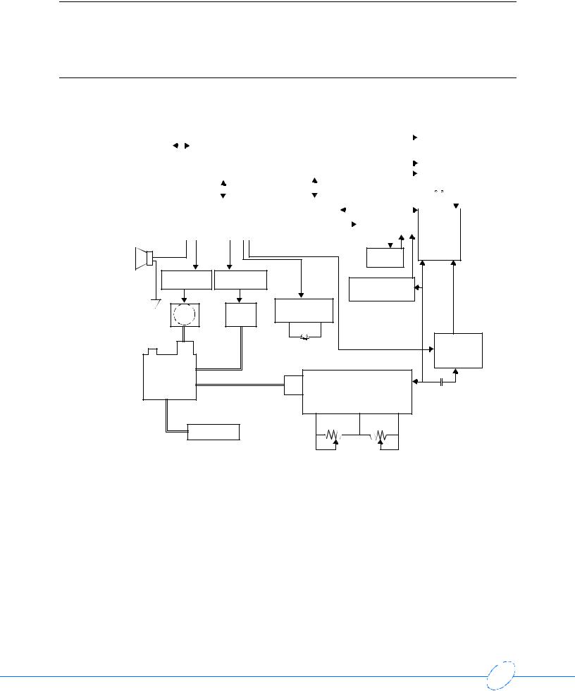
90207 Block Diagram
IR |
|
|
|
|
|
|
|
|
|
|
|
|
|
|
|
|
|
|
|
|
|
4 AA cells |
|
|
|
|
|
|
|
|
|
|
|
|
+8.6 Ref |
||
|
|
|
|
|
|
|
|
|
|
|
|
|
|
|
|
|
|
|
|
|
|
|
|
|
|
|
|
|
|
|
|
|
|||||
|
|
|
|
|
|
|
|
|
|
|
|
|
|
|
|
|
|
|
|
|
|
|
|
|
|
power |
|
|
|
|
+4.7 V |
||||||
serial |
|
|
|
|
IR |
|
|
|
|
|
|
|
|
|
|
|
|
|
|
|
|
|
|
|
|
|
|
|
|
|
|
|
|||||
|
|
|
|
|
|
|
|
|
|
|
|
|
|
|
|
|
|
|
|
|
|
|
|
|
|
|
|
|
|
|
|||||||
|
|
|
|
|
|
|
|
|
|
|
|
|
|
|
|
|
|
|
|
|
|
|
|
|
|
|
|
||||||||||
I/O |
|
|
|
|
transmitter/ |
|
|
|
|
|
LCD screen |
|
|
|
|
|
|
|
|
|
|
|
supply |
|
|
|
|
+5 UR |
|||||||||
|
|
|
|
|
|
|
|
|
|
|
|
|
|
|
|
|
|
|
|
|
|
|
|
||||||||||||||
comm. port |
|
|
|
|
receiver |
|
|
|
|
|
|
|
|
|
|
|
|
|
3 volt lithium |
|
|
|
|
|
|
|
|
|
+10 UR |
||||||||
|
|
|
|
|
|
|
|
|
|
|
|
|
|
|
|
|
|
|
|
backup battery |
|
|
|
|
|
|
|
|
|
|
|
||||||
|
|
|
|
|
|
|
|
|
|
|
|
|
|
|
|
|
|
|
|
|
|
|
|
|
|
|
|
|
|
|
-5 UR |
||||||
|
|
|
|
|
|
central processing |
|
|
|
|
|
|
|
|
|
|
|
|
|
|
ON/OFF |
|
low |
||||||||||||||
|
|
|
|
|
|
|
|
|
|
|
|
|
|
|
|
|
|
|
|
|
|
|
|
|
|||||||||||||
|
|
|
|
|
|
|
|
|
|
|
|
|
|
|
|
|
|
|
|
|
|
data/control |
|
|
|
switch |
|
batteries |
|||||||||
|
|
|
|
|
CPU / internal ROM |
|
|
|
|
|
|
RAM |
|
|
|
|
|
|
|
|
|
|
|
|
|
|
|
|
|
|
|
|
|
|
|||
|
|
|
|
|
|
|
|
|
|
|
|
|
|
|
|
|
|
|
|
|
|
real |
|
|
fault |
|
|
|
|
|
|
|
|
|
|||
|
|
|
|
|
|
|
|
|
|
|
address logic |
|
|
|
|
|
|
|
time |
|
|
detect |
oscillometric |
||||||||||||||
|
|
|
|
|
device latch |
|
|
|
|
|
|
|
|
|
|
clock |
|
|
|
|
|
|
amplifier |
|
|
|
|
|
|||||||||
|
|
|
|
|
|
|
|
|
|
|
|
|
|
|
|
|
|
|
|
|
|||||||||||||||||
|
|
|
|
|
|
|
|
|
|
|
|
|
|
|
|
|
|
|
|
|
|
|
|
|
|
|
|
|
|
|
|
||||||
|
|
|
|
|
|
|
|
|
|
|
|
|
|
|
|
|
|
|
|
|
|
|
|
|
|
|
|
|
|
|
|
|
|
|
|
|
|
|
|
|
|
|
watch dog |
|
|
|
|
|
hold |
timer |
|
|
|
|
|
|
|
|
speaker |
|
motor speed |
valve ON |
|
|
|
|
|
control circuit |
control circuit |
|
over pressure |
|
|
|
|
|
|
detector |
|
|
|
air |
air |
start up logic |
|
|
|
|
pump |
valve |
|
|
|
internal |
|
|
|
|
|
|
overpressure |
internal |
|
|
|
||
relief valve |
|
Start/Stop |
gain and DC restore |
oscillometric |
||
|
check |
|
||||
|
|
valve |
|
button |
|
amplifier |
|
|
|
|
|
|
|
|
manifold |
|
|
|
|
|
assembly |
|
|
|
|
||
|
|
|
|
|
pressure amplifier |
AC coupling |
|
|
|
|
pressure |
|
|
|
|
|
|
transducer |
|
|
|
|
pressure cuff |
|
|
|
|
gain adjust |
offset adjust |
Figure 3-1: 90207 block diagram
3-4

90207 Ambulatory Blood Pressure Monitor Service Manual
Wake Up and Power Up Logic
The 90207 power up sequence can be initiated by any of the following actions:
•Power START/STOP switch turned ON
•START/STOP switch depressed
•REAL TIME CLOCK generates minute change pulse
•IR serial RS-232 cable connected to communications port
The first three of the above actions trigger a wake-up pulse from a one-shot generator to assert the PWR_ENABLE line and to enable the converter supply. When asserted, the PWR_ENABLE line applies power to the microprocessor and generates a restart condition, causing the 90207 circuits to awaken. The microprocessor then sets the HOLD line high to keep the converter supply up, even after the wake-up one-shot pulse has timed out (the wake-up one-shot pulse has a duration of approximately 120 msec).
After a wake-up, the microprocessor determines which event initiated the wake-up:
•It checks the C_CON (cable connected) line to determine if the IR RS-232 serial cable activated the supplies.
•It checks the START/STOP line to see if this button is being pressed.
•It checks the PWR_SW line to see if the unit was just powered ON.
If none of these three conditions was responsible for waking up the unit, the minute timer is assumed to have generated the wake-up pulse.
START/STOP Button
Pressing the START/STOP button triggers the wake-up one-shot generator and also generates an interrupt to the microprocessor that is processed after the converter supplies are activated. The microprocessor has a restart time of about 70 msec. After the restart time, the microprocessor asserts the HOLD line and processes the interrupt (if the IR RS-232 cable is not connected), which initiates the restart.
Power Switch
When the main power switch contacts are closed, power (+VSB) is applied to a power switch flipflop circuit. This flip-flop is then cleared and the PWR_SW line to the processor goes high (since the processor is not yet powered ON, a resistor is used to protect the microprocessor input).
At the same time, the wake-up one-shot generator is triggered. This in turn activates the converter supplies and awakens the microprocessor. The microprocessor now checks for conditions START/STOP and C_CON. The PWR_SW line is read to determine if the power-up condition was initiated by the power switch being ON. If ON, the HOLD line is asserted to clear the PWR_SW line.
Theory
3-5

90207 Ambulatory Blood Pressure Monitor Service Manual
Minute Pulse
The clock produces a pulse with a duration of 30 seconds every minute. The leading edge of this pulse causes the minute timer flip-flop to change states. A narrow pulse (about 500 nsec) is generated that also resets the flip-flop. This pulse triggers the wake-up one-shot, which in turn powers up the converter and activates the microprocessor.
After waking up, the microprocessor first checks to see if any of the three possible wake-up conditions has awakened it (C_CON, START/STOP LINE, or PWR_SW). If none of these three have awakened the microprocessor, the microprocessor then asserts the HOLD line and determines if it is time for a pressure reading. If it is time for pressure reading, the reading is initiated; if it is not time for a pressure reading, the display time is updated, the HOLD line is removed, and the microprocessor returns to its sleep state.
Cable Connection
If a cable is connected to the 90207 RS-232 communications connector and the power switch is in the ON position, the power converter will be activated, bringing up the microprocessor. When receiving a C_CON wake-up, the microprocessor gives it priority over the other three wake-up conditions. A C_CON wake-up also prevents the power convertor from being deactivated as a result of a shutdown fault, which might be generated by the watch dog timer or overpressure detector.
After wake-up, the microprocessor goes into a listening mode and waits for instructions from the attached computer. These instructions adhere to the ABP communications protocol.
Second Pulse
The SECONDS line from the unit’s real-time clock is monitored by the watch dog timer to determine how long a pressure reading takes. When the unit wakes up, a reset signal is sent to the watch dog timer, setting it to zero time. When the watch dog counts 256 second pulses, it generates a pulse to activate the fault shutdown flip-flop circuit. The SECONDS line also goes to the display circuit where it is used to blink the display colon and change polarity to the LCD display.
Watch Dog Timer
The watch dog timer ensures that the cuff cannot remain inflated if the 90207 software crashes. This timer begins counting second pulses from the real-time clock at converter power up. When it counts up to 256-second pulses, the diode-connected outputs of the counter go high, causing a transistor to pull low on the trigger input of the fault shutdown one-shot generator. This triggers a 25-second pulse, which asserts the shutdown line.
3-6

90207 Ambulatory Blood Pressure Monitor Service Manual
Fault Shutdown
The fault shutdown circuitry causes the power converter to shut down. It also disables the pressure pump and opens the pressure release valve until the shutdown circuit times out in approximately 25 seconds. Shutdown can be caused by two conditions:
•There is an overpressure situation that is not detected by software.
•The pressure reading takes longer than 256 seconds. This duration indicates a software crash, because there is also a 180-second software time-out that should have already stopped the reading.
Overpressure Detector
In addition to software overpressure detecting, there is also a hardware overpressure detector (at approximately 310 mmHg) that detects an overpressure situation that lasts longer than one-half of a second. This small delay prevents motion artifacts from causing false overpressure detection.
Pressure Amplifier
The pressure amplifier circuitry amplifies voltage produced across the pressure transducer. This voltage is proportional to the pressure in the arm cuff. The pressure transducer requires compensation to make the voltage output linear with pressure. This compensation is accomplished with a reference voltage and a current source. The current source provides an output that increases as the voltage across the bridge decreases. This linearizes the transducer’s output voltage.
Voltage across the transducer is amplified differentially and converted into single-ended voltage. This voltage is amplified and sent to the A/D converter (ADC0848), the oscillometric amplifier, and the overpressure detector.
Offset Adjust
Transducer offset is nulled out using a pressure offset adjustment. Minor variations in the offset are tracked and compensated for through software.
Gain Adjust
Variations in gain can be compensated for with gain adjustment. The voltage gain to the A/D converter is +14.4 mv/mmHg. This voltage is offset by about 0.2 volts. The 0.2 volts is inserted into the last stage to prevent the signal to the A/D converter from going negative. The 0.2-volt offset is subtracted with software.
Pressure Amplifier Filters
Some filtering is done in the pressure channel to reduce the effect of the pumping action, which adds pulses to the pressure in the cuff. A 23-Hz low pass filter serves this purpose. The R-C combination at the pressure output prevents the A/D converter loading from affecting the oscillometric waveform.
Theory
3-7

90207 Ambulatory Blood Pressure Monitor Service Manual
Oscillometric Amplifier
The first two stages of the oscillometric amplifier are a 2-pole low-pass filter and a 2-pole highpass filter. Together, these filters produce an insertion loss of 30%. The center frequency of the pass band is 2 Hz; the 3-db points are at about 0.9 Hz and 5.5 Hz. During cuff bleeds and cuff inflation, the high-pass filter is restored to charge the coupling capacitor up to the new pressure level voltage. This helps reduce filter settling time.
Filtering has the effect of narrowing the oscillometric pulse width and generating a pulse with an amplitude that is proportional to the rising edge of the oscillometric input waveform and its original amplitude. The oscillometric pulse is similar to a half-sine wave with an extended trailing edge.
Gain Switching
Gain switching is provided by the oscillometric amplifier to account for varying amplitudes of the oscillometric pulse. Switching is done by using switching gain resistors with analog switches (DG211) selected by the GAIN_0 and GAIN_1 lines. Gain can be selected at 2, 4, 8, or 16.
Offset and Limiting
The offset stage offsets the voltage to the A/D converter to prevent negative voltages from going to the converter. The input offset of the amplifiers can cause as much as 0.6 volts of unwanted offset at the oscillometric output. Offset is subtracted out with software.
The last stage in the oscillometric amplifier limits the output swing from 0 to +4.7 volts to prevent over-driving the A/D converter input.
Digital Circuitry Display Board
Information is sent from the microprocessor to the LCD controller by a serial bus (CBUS). The LCD controller activates the necessary segments separately to display information on the 4- segment LCD. The microprocessor determines what segments are to be turned on, sending this information to the controller.
An exclusive OR gate blinks the colons once each second when in the clock mode, and it also changes polarity of the drive.
Real-Time Clock
The real-time clock uses a serial data bus to send and receive information. This bidirectional bus is divided into two lines (transmit and receive) that go to the microprocessor. If the main batteries are removed, the clock will be backed up for approximately 2 minutes by the 3-volt lithium cell.
RAM
RAM is a 32 KB x 8 bit device for storing both patient collected information and programmed information. RAM data is backed up during main battery removal by the 3-volt lithium cell.
3-8

90207 Ambulatory Blood Pressure Monitor Service Manual
Addressing and Control Lines
Unit addressing and control is accomplished with a combination of microprocessor ports, two latches, and one-half of a multiplexer circuit. The 74HC174 latch controls the motor, valve, alert, gain switching, and hold line. A 74HC373 provides address latching for the RAM.
Communications RS-232 Connector
The 90207 communications connector is a modified RS-232 interface. When the communications cable (IR cable) is connected to the back of the 90207, a reed relay is activated, causing power to be applied to the ABP unit.
The microprocessor checks and determines that the C_CON line is asserted. It then goes into communication mode. The microprocessor must then determine whether the cable is communicating with a modem, a PC direct interface, or a local report generator. It then responds accordingly.
Communications are accomplished by means of a transmit and a receive line. The data is converted into IR signals.
Microprocessor
The 90207 uses a 80C51 microprocessor with a 7.272-MHz crystal. This chip contains on board RAM and ROM. Four 8-bit ports provide the data lines, the addressing, and the control and serial bus lines.
The on-board ROM provides routines for communications and start up. The majority of the program is loaded into RAM using the IR RS-232 port.
One interrupt is used, and it is initiated by these following conditions:
•The START/STOP line goes low
•The PWR_SW line and the ADC INT lines go low (lowest-priority interrupt)
Theory
3-9
Loading...