

Page 1

Ultraview® Care Network
Reference Guides
Refer to the Operations Manual for full instructions
073-1001-17 Rev. E
Page 2

Alarms Reference Guide
To set alarm limits:
1 Touch a parameter key (ECG,
TEMP, etc.).
2 Touch ALARM LIMITS.
3 Ensure ALARMS ON is set.
4 Select HI = or LO =.
5 Use arrow keys to adjust.
To silence an alarm tone for
45 seconds at any monitor,
touch the TONE RESET/ALM
SUSPEND key once.
To set local alarm tones or
key tones:
1Touch MONITOR SETUP.
2 Touch TONES.
3 Select LOCAL ALARMS or
KEY TONE.
4 Select TONES ON.
5Use VOLUME↑ and VOLUME↓
keys to adjust.
To suspend alarms at a
bedside monitor when no
alarm is sounding, touch the
TONE RESET/ALM
SUSPEND key once.
To set alarm watch tones or
remote view tones:
1 Touch MONITOR SETUP.
2 Touch TONES.
3 Select ALARM WATCH or
REMOTE ALARMS.
4 Select TONES ON.
5Use VOLUME↑ and VOLUME↓
keys to adjust.
To resume normal alarm
operation at a bedside
monitor within the 3-minute
period, touch the TONE
RESET/ALM SUSPEND or
RESUME ALARMS
To resume alarm tones at a
central monitor, touch the
TONE RESET/ALM
SUSPEND key again.
To enable Alarm Watch:
1 Touch SPECIAL FUNCTIONS.
2 Touch ALARM WATCH.
3a Select a bed or a subnet.
3b If you selected a subnet, then
select a bed.
4 Ensure that the key for the
desired bed(s) has the ON
segment highlighted or is
indented.
5 Touch ALARM WATCH
ENABLE for the UCW and
Ultraview 1700.
• This guide is intended as an abbreviated reference only; it is not intended to replace the full operational
!
073-1001-17 Rev. E ©2004 Spacelabs Medical, Inc. · www.spacelabs.com · 51 50 220th Ave SE · Issaquah WA 98029 · 800.522.7025
instructions documented in the operations manual that accompanied your product. Please read your
operations manual prior to operating your system and refer to it for full instructions.
To disable Alarm Watch:
1 Touch SPECIAL FUNCTIONS.
2 Select RV/AW OFF.
To de-select beds for Alarm
Watc h:
1 Touch SPECIAL FUNCTIONS.
2 Touch ALARM WATCH.
3a Touch the bed to de-select.
-OR-
3b Touch DESELECT ALL.
(Ultraview 1030, 1050, 1500,
and 1600 monitors) key
again.
To select parameters for
alarm recording and
generate automatic
recordings on a bedside
recorder:
1 Touch MONITOR SETUP.
2 Touch RECORDER CONFIG.
3 Select RECORDING
DESTINATION.
4 Select a destination for the
alarm recording.
5 Touch PREVIOUS MENU.
6 Touch ALARM PARAMS.
7 Select parameter key(s) ON to
initiate a recording in case of
alarm. If the parameter key is
OFF, no alarm recording is
produced for that parameter in
an alarm condition.
Page 3

Alarms Troubleshooting Guide
Clinical Situation Possible Cause Solution
Duplicate alarm
recordings print at the
bedside and system
printer
■ Alarm recording directed to both
bedside and network printers under
the RECORDING DESTINATION
key.
■ Select THIS MONITOR or NETWORK
for alarm recordings.
No alarm recordings
are printed
Alarms continue to
violate after touching
TONE RESET
No alarm notification
occurs at a central
monitor
CANNOT INTERACT
WITH ALARM WATCH
parameter displayed
■ Parameters for alarm recordings are
set to OFF.
■ Bedside printer is OFF.
■ The alarms have not been directed
to the bedside printer.
■ ALARMS SUSPENDED for
3-minutes.
■ System printer is not identified as
one of two network printers.
■ Printer is out of paper. ■ Load paper into printer.
■ More than one alarm may be in
violation.
■ The Alarm Watch function is not
active.
■ Parameters not displayed. ■ Display the desired parameters using
■ The monitor may not be configured
to allow interaction with remote
parameters.
■ Select parameters for alarm
recordings from the Alarm Parameters
menu or Record Alarm Parameters
menu.
■ Turn bedside printer ON.
■ Ensure that THIS MONITOR or BOTH
is selected.
■ Ensure that alarms are not
suspended.
■ Have your system administrator verify
configuration.
■ Touch TONE RESET/ALM SUSPEND
again.
■ Activate Alarm Watch for the desired
beds at the central.
SCREEN FORMAT under MONITOR
SETUP.
■ Contact your system administrator.
073-1001-17 Rev. E ©2004 Spacelabs Medical, Inc. · www.spacelabs.com · 5150 220th Ave SE · Issaquah WA 98029 · 800.522.702 5
Page 4

Admit Reference Guide
To enter new patient
information (Ultraview
1030/1050/1500/1600):
1 Touch MONITOR SETUP.
2 Touch ADMIT/DISCHARGE.
3 Touch ADMIT.
4 Select YES to purge the
existing data.
5 Select ID and/or NAME.
6 Enter information using the
on-screen keyboard.
7 Touch ENTER.
8 Touch PREVIOUS MENU
(if necessary).
9 Select DATE OF BIRTH and
enter MONTH, DAY, and
YEAR.
10 Touch ENTER.
11 Touch PREVIOUS MENU.
12 Select HEIGHT, WEIGHT, or
BSA and enter information
using the on-screen keypad.
13 Touch ENTER.
14 Touch MALE/FEMALE until the
correct gender is highlighted.
15 Touch ADULT/NEONATE until
the relevant selection is
highlighted.
To enter new patient
information (UCW/
Ultraview 1700):
1 Touch MONITOR SETUP.
2 Touch ADMIT/DISCHARGE.
3a Select a subnet or a bed
(central only).
3b If you selected a subnet, then
select a bed.
4 Touch ADMIT.
5 Select YES to purge the
existing data.
6 Select a field on the on-screen
keyboard.
7 Enter information using the
on-screen keyboard.
8 Touch ENTER after completing
each field.
9 Select ADULT or NEONATE.
10 Select MALE or FEMALE.
11 Touch ACCEPT to store the
new patient data.
To change patient
information:
1 Touch MONITOR SETUP.
2 Touch ADMIT/DISCHARGE.
3a Select a subnet or a bed
(central only).
3b If you selected a subnet, then
select a bed.
4 Touch CHANGE DATA.
5 Make desired changes as
described under Entering New
Patient Information in the Admit
chapter of the UCN Operations
Manual.
To discharge a patient:
1 Touch MONITOR SETUP.
2 Touch ADMIT/DISCHARGE.
3a Select a subnet or a bed
(central only).
3b If you selected a subnet, then
select a bed.
4 Touch DISCHARGE.
5 Select YES to purge the
existing data.
• This guide is intended as an abbreviated reference only; it is not intended to replace the full operational
!
073-1001-17 Rev. E ©2004 Spacelabs Medical, Inc. · www.spacelabs.com · 51 50 220th Ave SE · Issaquah WA 98029 · 800.522.7025
instructions documented in the operations manual that accompanied your product. Please read your
operations manual prior to operating your system and refer to it for full instructions.
Page 5

Admit Troubleshooting Guide
Clinical Situation Possible Cause Solution
Patient name incorrect
as entered on
keyboard menu
■ Name exceeds 40 character
maximum and system has written
over some characters.
■ No patient name or ID number
stored in system.
■ Re-enter name using 40 characters or
less.
■ Enter name or ID number.
073-1001-17 Rev. E ©2004 Spacelabs Medical, Inc. · www.spacelabs.com · 5150 220th Ave SE · Issaquah WA 98029 · 800.522.702 5
Page 6

Printing Reference Guide
To start a manual recording
via the monitor:
1 Touch RECORD.
2 Touch up to four flashing
parameter keys.
3a Touch CANCEL RECORD
SELECTION(S) to terminate.
-OR-
3b Touch STOP RECORDING in
the PRINTER CONTROLS
menu to terminate.
To print group recordings
via the monitor:
1 Touch RECORD twice.
2a Touch RECORD ALL.
-OR-
2b Touch RECORD
PRESELECTED A or B.
To load paper in the
Ultraview 1030/1050 printer:
1 Press release button on door.
2 Open paper tray door all the
way.
3 Snap new roll into place.
4 Pull out 6 to 12 inches of paper.
5 Close door.
To start a continuous
recording via the monitor:
1 Touch RECORD.
2 Touch CONTINUOUS
RECORD, then touch the
desired parameter key (up to
four, for each parameter to be
continuously recorded.
3 Touch CANCEL RECORD
SELECTION to restart the
selection process.
To load paper in a bedside
printer module (2-channel
only):
1 Press eject button next to
PAPER OUT light.
2 Withdraw plastic paper tray.
3 Discard old cardboard retainer
inside tray.
4 Remove label from new paper
but keep cardboard retainer in
place around one end.
5 Start inserting paper into tray,
beginning with cardboard
retainer end.
6 With paper halfway into tray, lift
up spring-loaded roller.
7 Bring out top fold of paper from
under top end of cardboard
retainer.
8 Bring top fold over top of
spring-loaded roller.
9 Release spring-loaded roller
onto remainder of paper.
10 Insert stack fully.
11 Unfold paper and position over
top of black roller at end of tray.
12 Slide tray completely back into
printer module.
To stop a continuous
recording via the monitor:
1 Touch RECORD.
2a Touch STOP CONT.
RECORD.
-OR-
2b Touch STOP RECORDING in
PRINTER CONTROLS.
To load paper in a system
printer module (2- or
4-channel):
1 Press eject button next to
PAPER OUT light.
2 Withdraw plastic paper tray.
3 Discard old cardboard retainer
inside tray (2-channel only).
4 Remove label from new paper
but keep cardboard retainer in
place around one end
(2-channel only).
5 Discard 4-channel container.
6 Start inserting paper into tray,
beginning with cardboard
retainer end (2-channel only).
7 Make sure black squares are in
the top left corner of the pages
(4-channel).
8 Insert stack fully.
9 Unfold paper and position over
top of black roller at end of tray.
10 Slide tray completely back into
printer module.
• This guide is intended as an abbreviated reference only; it is not intended to replace the full operational
!
073-1001-17 Rev. E ©2004 Spacelabs Medical, Inc. · www.spacelabs.com · 51 50 220th Ave SE · Issaquah WA 98029 · 800.522.7025
instructions documented in the operations manual that accompanied your product. Please read your
operations manual prior to operating your system and refer to it for full instructions.
Page 7

Printing Troubleshooting Guide
Clinical Situation Possible Cause Solution
Printer displays
PAPER OUT message
■ Printer is out of paper. ■ Load paper (refer to Loading Paper in
■ Printer door is open.
■ Paper was loaded improperly.
the Printing chapter of the UCN
Operations Manual P/N 070-1001-xx).
Printer fails to print
self-test strip
Message UNABLE TO
RECORD THE
REQUESTED
CHANNEL is displayed
CONTINUOUS
RECORD key not
displayed
■ Failed internal diagnostics. ■ Notify qualified service person.
■ Printer not active.
■ Printer not selected by a system
administrator.
■ Printer is out of paper.
■ Menu is at the bottom of the screen. ■ Touch NORMAL SCREEN, then
■ Toggle PRINTER ON/OFF key.
■ Check with your hospital biomed or
system administrator.
■ Load paper.
RECORD.
073-1001-17 Rev. E ©2004 Spacelabs Medical, Inc. · www.spacelabs.com · 5150 220th Ave SE · Issaquah WA 98029 · 800.522.702 5
Page 8

Bedside Monitors Reference Guide
To adjust screen clarity:
1 Touch MONITOR SETUP.
2 Touch MONITOR CONFIG.
3a Touch BRIGHTNESS.
-OR-
3b Touch CONTRAST.
-OR-
3c Touch
BRIGHTNESS/CONTRAST
(for Ultraview 1500 only).
4 Use arrow keys to adjust.
To access the clock menu
(UCW and Ultraview 1700
only):
1 Touch MONITOR SETUP.
2 Touch MONITOR
CONFIGURATION.
3 Select CLOCK ON.
4 Touch the clock that appears in
the lower right of the screen.
5 Select DIGITAL,
STOPWATCH, or TIMER.
To connect to an external
power supply (Ultraview
1030 and 1050 only):
NOTE: Charging takes place only
when plugged into an AC outlet.
1 Attach the DC outlet cable to
J1.
2 Connect the power cord of the
external power supply to an AC
outlet.
• This guide is intended as an abbreviated reference only; it is not intended to replace the full operational
!
073-1001-17 Rev. E ©2004 Spacelabs Medical, Inc. · www.spacelabs.com · 51 50 220th Ave SE · Issaquah WA 98029 · 800.522.7025
instructions documented in the operations manual that accompanied your product. Please read your
operations manual prior to operating your system and refer to it for full instructions.
To transfer data:
1 Touch ECG.
2 Touch SETUP.
3 Select TRANSFER DATA.
4 Remove module after DATA
TRANSFER COMPLETED is
displayed.
5 Insert module into a monitor to
retrieve the data.
6 Touch RETRIEVE DATA.
7 Touch YES.
To select parameters for
display at remote monitors:
1 Touch MONITOR SETUP.
2 Touch OUTBOUND
PARAMETERS.
3 Select the parameters you wish
to display (up to five).
To change parameters for
display at remote monitors:
1 Touch MONITOR SETUP.
2 Touch OUTBOUND
PARAMETERS.
3 Deselect the parameter key
that you wish to stop
displaying.
4 Select the parameter you wish
to display.
To start capnography
monitoring (Ultraview 1030
and 1050 only):
1 Plug the mainstream EtCO2
sensor cable into the EtCO2
receptacle on the capnogra phy
panel.
2 If necessary, perform the
sensor calibration:
2a Place the sensor on the zero
cell and wait for the completion
message to display on the
screen. Sensor cells are
located on the sensor cable
and are labelled “O” and “REF”.
2b Place the sensor on the
reference cell and wait for the
completion message to display
on the screen.
3 Prepare the patient according
to hospital procedures.
4 Select the appropriate airway
adapter (neonate or adult).
5 Verify that the windows are
clean and dry.
6 Place the sensor head over the
airway adapter and perform an
adapter calibration, if
necessary.
7 Remove the airway adapter
from the sensor head.
8 Insert the airway adapter into
the ventilator circuit and Ballard
style tracheal suction system
(if present) as shown.
9 Attach the sensor head to the
airway adapter.
10 Make the other connections as
shown in Figure 5-13 in the
UCN Operations Manual.
11 Ensure that the sensor head is
always positioned above the
ventilator circuit so that
moisture will not enter the
adapter.
Page 9

Bedside Monitors Troubleshooting Guide
Clinical Situation Possible Cause Solution
Cannot change
parameter priority or
colors
■ Monitor may not be set up to allow
the user to change priority or colors.
■ Contact your system administrator.
Changed parameter
priority or colors are
lost
Transport monitor has
no DC power
■ The STORE key was not touched
after the selection was made.
■ The monitor was not plugged into an
AC outlet while not in use.
■ No batteries installed.
■ Touch the STORE key to make
changes permanent.
■ Plug the monitor into an AC outlet to
recharge the batteries.
■ Install one or two batteries.
073-1001-17 Rev. E ©2004 Spacelabs Medical, Inc. · www.spacelabs.com · 5150 220th Ave SE · Issaquah WA 98029 · 800.522.702 5
Page 10

Central Monitors Reference Guide
To select remote parameters
for display:
1 Touch MONITOR SETUP.
2 Touch SCREEN FORMAT.
3 Select a bed (or a subnet, then
a bed).
4 Select the parameter(s) to be
displayed.
5 Select a zone.
To change the network or
internal system time and
date:
1 Touch MONITOR SETUP.
2 Touch PRIVILEGED ACCESS.
3 Enter Clinical password.
4 Touch TIME/DATE.
5a Select TIME.
-OR-
5b Select DATE.
6a Select 24 HOURS or AM/PM
(12 hours).
-OR-
6b Select MONTH, DAY, and
YEAR.
7 Use arrow keys to set time or
date.
8 Touch ENTER.
To assign color to a zone:
1 Touch MONITOR SETUP.
2 Touch SCREEN FORMAT.
3 Touch the desired color.
4 Touch the zone to be colored.
To enable/disable the clock:
1 Touch MONITOR SETUP.
2 Touch MONITOR
CONFIGURATION.
3a Select CLOCK ON to enable
the clock.
-OR-
3b Select CLOCK OFF to disable
the clock.
To activate the screen saver:
1 Touch MONITOR SETUP.
2 Touch MONITOR
CONFIGURATION.
3 Touch ACTIVATE SCREEN
SAVER.
To access the clock menu:
1 Touch MONITOR SETUP.
2 Touch MONITOR
CONFIGURATION.
3 Select CLOCK ON.
4 Touch the clock that appears in
the lower right of the screen.
5 Select DIGITAL,
STOPWATCH, or TIMER.
To enable Data
Communications Watch
(must have system
administrator menu access):
1 Touch MONITOR SETUP.
2 Touch PRIVILEGED ACCESS.
3 Enter Biomed password.
4 Touch MORE.
5 Touch DATA COMM WATCH.
6 Select COMM WATCH ON.
7 Select ALARM ON to enable
DCW alarms.
8 Select ADMIT REQUIRED ON
to enable DCW for admitted
patients only.
• This guide is intended as an abbreviated reference only; it is not intended to replace the full operational
!
073-1001-17 Rev. E ©2004 Spacelabs Medical, Inc. · www.spacelabs.com · 51 50 220th Ave SE · Issaquah WA 98029 · 800.522.7025
instructions documented in the operations manual that accompanied your product. Please read your
operations manual prior to operating your system and refer to it for full instructions.
Page 11

Central Monitors Troubleshooting Guide
Clinical Situation Possible Cause Solution
Cannot assign color to
a zone
■ Monitor may not be set up to allow
you to assign colors.
■ Contact your system administrator.
Cannot assign a
parameter to a zone
Cannot access the
clock menu
CANNOT deselect
ALARM WATCH
■ Zone may not have been cleared of
previous assigned waveforms.
■ Clock may have been left in
STOPWATCH or TIMER mode.
■ The Ultraview Central Monitor is
configured with Central Alarm Watch
Manager to prevent de-selection of
automatically alarm watched beds.
■ Select CLEAR ZONE, then touch the
zone in which to display the new
parameter. Repeat the initial SCREEN
FORMAT steps.
■ Touch the clock/timer display, then
touch PREVIOUS MENU to restore
the clock.
■ Contact your system administrator.
073-1001-17 Rev. E ©2004 Spacelabs Medical, Inc. · www.spacelabs.com · 5150 220th Ave SE · Issaquah WA 98029 · 800.522.702 5
Page 12

Module Configuration Manager Reference Guide
To review or change
settings:
Module Configurations with
ECG
1 Touch ECG.
2 Touch SETUP.
3 Touch CONFIG.
4 Touch the hidden key 3 times.
5 Touch USER SETTINGS.
6a Select ECG.
-OR-
6b Select RESP.
-OR-
6c Select VARITREND.
-OR-
6d Select PRESSURE.
-OR-
6e Select SPO2.
-OR-
6f Select NIBP.
-OR-
6g Select TEMP.
7 Use CURSOR↑ and
CURSOR↓ to scroll through the
parameter description list.
8 Use ↑ and ↓ to change the
settings.
9 Touch NEXT PAGE to continue
to next screen of parameters.
10 Touch STORE to save the new
settings.
11 Touch YES when the STORE
ALL CHANNEL DEFAULTS
message is displayed.
To review or change
settings:
Module Configurations
without ECG
1 Touch TEMP.
2 Touch the hidden key 3 times.
3 Touch USER SETTINGS.
4a Select PRESSURE.
-OR-
4b Select SPO2.
-OR-
4c Select TEMP.
5 Use CURSOR↑ and
CURSOR↓ to scroll through the
parameter description list.
6 Use ↑ and ↓ to change the
settings.
7 Touch NEXT PAGE to continue
to next screen of parameters.
8 Touch STORE to save the new
settings.
9 Touch YES when the STORE
ALL CHANNEL DEFAULTS
message is displayed.
To transfer user-defined
settings from the module
into the monitor:
Module Configurations with
ECG
1 Touch ECG.
2 Touch SETUP.
3 Touch CONFIG.
4 Touch the hidden key 3 times.
5 Touch TRANSFER
SETTINGS.
6 Select YES.
Module Configurations
without ECG
1 Touch TEMP.
2 Refer to steps 4 through 6
above.
To retrieve user-defined
settings from the monitor
into another module:
Module Configurations with
ECG
1 Touch ECG.
2 Touch SETUP.
3 Touch CONFIG.
4 Touch the hidden key 3 times.
5 Touch RETRIEVE SETTINGS.
6 Select YES.
Module Configurations
without ECG
1 Touch TEMP.
2 Refer to steps 4 through 6
above.
• This guide is intended as an abbreviated reference only; it is not intended to replace the full operational
!
073-1001-17 Rev. E ©2004 Spacelabs Medical, Inc. · www.spacelabs.com · 51 50 220th Ave SE · Issaquah WA 98029 · 800.522.7025
instructions documented in the operations manual that accompanied your product. Please read your
operations manual prior to operating your system and refer to it for full instructions.
Page 13

ECG Reference Guide
To prepare the patient:
1 Wash the area where you plan
to place an electrode with soap
and water.
2 If necessary, shave the area
where you plan to position the
electrodes.
3 Clean the skin with alcohol.
4 Dry the skin thoroughly.
5 Abrade the skin.
To apply ECG electrodes:
1 Attach electrode to lead wire.
2 Apply electrode to patient skin.
3 Stress loop the wires as
necessary.
To specify the patient type:
1 Touch ECG.
2 Touch SETUP.
3 Touch CONFIG.
4 Select ADULT or INFANT.
To monitor paced patients:
1 Touch ECG.
2 Touch SETUP.
3 Select PACED YES.
To change the lead
selection:
1 Touch ECG.
2 Touch LEAD CONTROL.
3 Touch 1ST LEAD or 2ND
LEAD.
4 Select lead.
To display six traces
(requires a 12-lead cable):
1 Touch ECG.
2 Touch DISPLAY FORMAT.
3 Select SPLIT VIEW ON.
To display twelve traces
(requires a 12-lead cable):
1 Touch ECG.
2 Touch DISPLAY FORMAT.
3 Select FULL VIEW ON.
To check the ECG
amplitude:
1 Touch ECG.
2 Touch SIZE.
3 Touch 1 mV CAL.
To select a primary heart
rate source:
1 Touch ECG.
2 Touch SETUP.
3 Touch RATE SOURCE.
4 Select the desired primary rate
source (ECG, ART, UA, or
SPO2).
To enable alternate rate
sources:
1 Touch ECG.
2 Touch SETUP.
3 Touch RATE SOURCE.
4 Set the desired alternate
source(s) to ON (ECG, ART,
UA, and/or SPO2).
To print recordings of all
leads:
1 Touch ECG.
2 Touch PRINT.
3 Touch ALL LEADS.
To restore default settings:
1 Touch ECG.
2 Touch SETUP.
3 Touch RESTORE SETTINGS.
4 Select YES.
• This guide is intended as an abbreviated reference only; it is not intended to replace the full operational
!
073-1001-17 Rev. E ©2004 Spacelabs Medical, Inc. · www.spacelabs.com · 51 50 220th Ave SE · Issaquah WA 98029 · 800.522.7025
instructions documented in the operations manual that accompanied your product. Please read your
operations manual prior to operating your system and refer to it for full instructions.
Page 14

ECG Troubleshooting Guide
Clinical Situation Possible Cause Solution
AC noise ■ Display resolution set to extended
Baseline wanders ■ Patient moving excessively. ■ Use stress loops to secure lead wires
Low amplitude ECG ■ Skin improperly prepared. ■ Abrade skin and reapply electrodes.
Module won’t learn ■ ECG signal too noisy for
No ECG trace ■ Improper attachment of ECG
Excessive alarms ■ Electrodes dry. ■ Repeat skin preparation and apply
mode (0.05 to 150 Hz).
■ Electrodes dry. ■ Repeat skin preparation and apply
■ Patient cable entwined with other
electrical devices.
■ Respiration artifact. ■ Select another lead or reposition the
■ Electrodes dry. ■ Repeat skin preparation and apply
■ Lead selected not showing QR S
complex with greatest amplitude.
■ Electrodes could be positioned too
near bone or muscle mass.
initialization.
■ ECG voltage below threshold. ECG
VOLTAGE TOO LOW message may
be displayed.
connector cable to the module/or
leads off.
■ Module is not seated into the
monitor or remote housing.
■ Alarm limits set too close to patient's
normal heart rate.
■ Excessive interference: patient
cable or wires routed too close to
other electrical devices.
■ Excessive patient movement or
muscle tremor.
■ Select monitor mode (0.5–40 Hz).
new moist electrodes.
■ Separate patient cable from all other
cables.
and cable to the patient.
electrodes.
new moist electrodes.
■ Check 12-lead ECG to determine
better monitoring lead and reposition
electrodes.
■ Select another lead or reposition
electrodes.
■ Improve signal quality by repeating
skin preparation and/or repositioning
electrodes.
■ Perform the following steps as needed.
1. Check cables, lead wires and
electrodes, then relearn patient
rhythm.
2. Change lead or reposition
electrodes.
■ Remove, then re-plug the connector
into the module or reconnect the leads.
■ Remove, then reinsert the module or
exchange the module.
new moist electrodes.
■ Readjust alarm limit.
■ Reroute cables and leads.
■ Reposition electrodes and use stress
loops to secure lead wires and cable to
the patient.
073-1001-17 Rev. E ©2004 Spacelabs Medical, Inc. · www.spacelabs.com · 5150 220th Ave SE · Issaquah WA 98029 · 800.522.702 5
Page 15
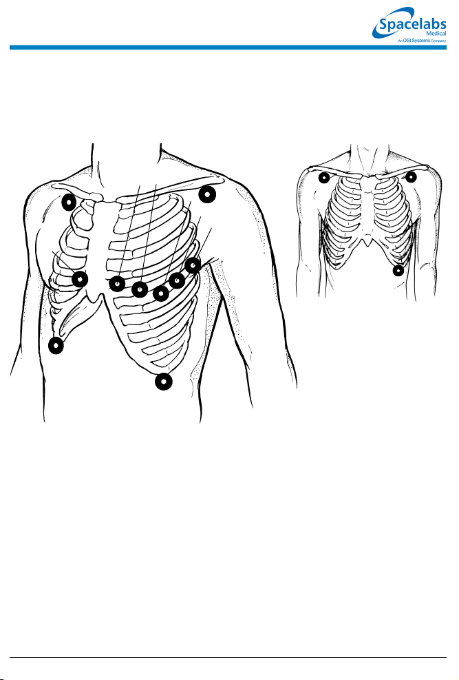
Precordial Leads: V1 - V
Limb Leads: I, II, III,
Augmented Leads: aVR, aVL, aVF
RA
V
1
RL
V14th intercostal space, right sternal margin
V
4th intercostal space, left sternal margin
2
V
Midway between V2 and V
3
V45th intercostal space, midclavicular line
V
Same level as V4 at anterior axillary line
5
V
Same level as V4 at midaxillary line
6
6
V2V
3
V
4
LA
V
5
V
6
LL
4
Adult Lead Placement
Limb Leads:
I, II, III
RA LA
LL
■ With some cables, the chest electrode must be repositioned on the patient’s
chest to view alternate precordial leads
073-1001-17 Rev. E ©2004 Spacelabs Medical, Inc. · www.spacelabs.com · 51 50 220th Ave SE · Issaquah WA 98029 · 800.522.7025
Page 16
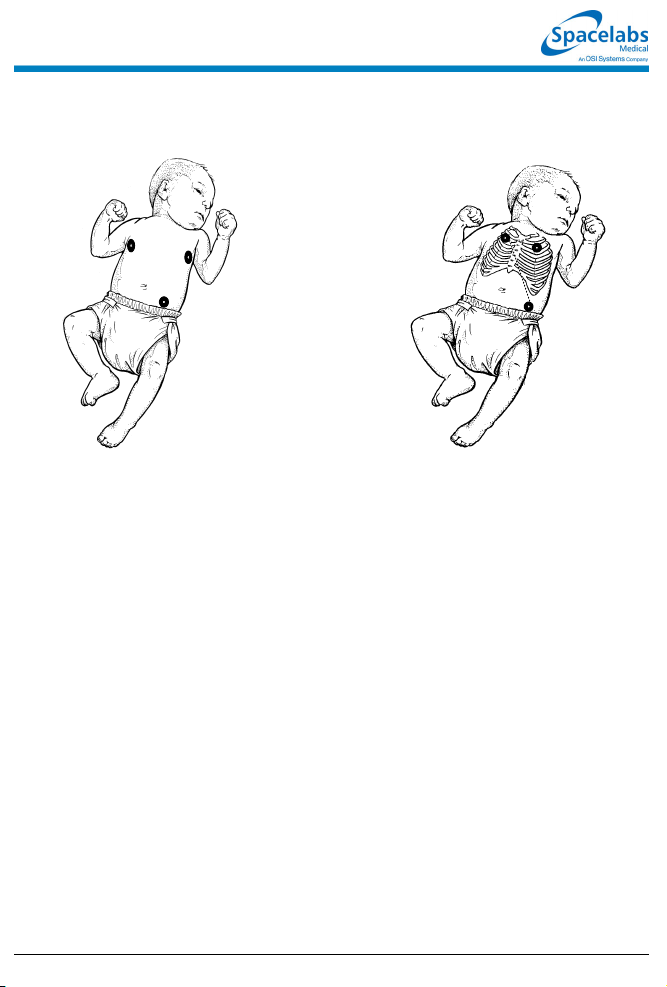
Neonate Lead Placement
RA
LA
LL
Maximum Impedance Change:
Position RA and LA electrodes at the
nipple level, midaxillary line. Position LL
below the diaphragm, preferably below
the umbilicus.
RA
Alternate Method:
Position RA and LA electrodes at the
2nd intercostal space, midclavicular
line. Position LL below the diaphragm,
preferably below the umbilicus.
LA
LL
• This guide is intended as an abbreviated reference only; it is not intended to replace the full operational
!
073-1001-17 Rev. E ©2004 Spacelabs Medical, Inc. · www.spacelabs.com · 51 50 220th Ave SE · Issaquah WA 98029 · 800.522.7025
instructions documented in the operations manual that accompanied your product. Please read your
operations manual prior to operating your system.
Page 17

Skin Preparation
■ Select a flat, nonmuscular area for
electrode placement.
■ Shave or clip hair — even fine hair.
■ Wash skin with soap and water to
remove dirt, oil, surgical scrub
solutions and dead skin.
■ Do not use soaps containing lotion.
■ Dry skin thoroughly.
■ Wipe skin with alcohol and let it dry
thoroughly.
■ Gently abrade the skin using the
scratch pad on the back of the
electrode or a dry towel.
■ If the patient is diaphoretic, apply
tincture of benzoin or other “skin
prep” solution where the electrode
patch will be adhered, leaving a hole
so the electrode gel will directly
contact the skin.
Electrode Application
■ Verify electrode expiration date has
not passed and gel is moist.
■ Attach lead wires to electrodes prior
to applying to the patient.
■ Affix electrodes to the patient by
pressing around the circumference
of the patch.
■ Do not apply pressure directly over
the electrode gel to avoid
dispersement or air trapping.
■ Stress-loop lead wire to the chest if
the patient is active or ambulatory.
■ Secure the ECG cable to the
patient’s gown.
■ Keep the ECG cable off the patient’s
chest and clear of other electrical
devices or wires.
■ Reprep the skin and apply fresh,
moist electrodes every 24 hours.
Left Ventricular
Wall Affected
Anterior V
Leads
Monitored
1-4
Coronary
Artery Involved
Left Coronary
Artery
Anteroseptal V
2-4
Left Anterior
Descending
Inferior
(Diaphragmatic)
Lateral I, aVL,
Posterior V
073-1001-17 Rev. E ©2004 Spacelabs Medical, Inc. · www.spacelabs.com · 51 50 220th Ave SE · Issaquah WA 98029 · 800.522.7025
II, III, aVF Right Coronary
Artery
Left Anterior Descending
V
, V
5
6
1-2
(Reciprocal Changes)
Circumflex
Right Coronary Artery
Circumflex
Page 18

Page 19

Arrhythmia Reference Guide
To set up arrhythmia
monitoring:
1 Set up system and patient for
standard ECG monitoring.
2 Touch ECG.
3 Touch SETUP.
4 Touch CONFIG.
5 Ensure ADULT is selected.
6 Select ARR ON.
To disable arrhythmia
detection:
1 Touch ECG.
2 Touch SETUP.
3 Touch CONFIG.
4 Select ARR OFF.
To review arrhythmias:
1 Touch ECG.
2 Touch REVIEW.
3a Select an arrhythmia class type
for review.
-OR-
3b Touch ARRHYTHMIA
REVIEW and then select an
arrhythmia class type for
review.
4 Select NEXT CLASS or PRIOR
CLASS keys to display other
classes.
To control arrhythmia
alarms:
1 Touch ECG.
2 Touch REVIEW.
3 Touch ARRHYTHMIA
REVIEW.
4 Select CPL, ABN or TACH.
5 Select ALARM YES or NO.
To clear a class or the most
recent event in a class:
1 Touch ECG.
2 Touch REVIEW.
3 Touch ARRHYTHMIA
REVIEW.
4 Select an arrhythmia class.
5 Touch CLEAR.
6 Select ENTIRE CLASS or
LAST EVENT.
To print recordings of ALL
arrhythmia events:
1 Touch ECG.
2 Touch PRINT.
3a Touch PRINT ALL.
-OR-
3b Touch ARR CLASSES.
To merge class or trend
data:
1 Touch ECG.
2 Touch REVIEW.
3 Touch ARRHYTHMIA
REVIEW.
4 Select an arrhythmia class.
5 Touch MERGE.
6 Use PRIOR CLASS or NEXT
CLASS to display the two
classes you wish to merge.
7 Select MERGE CLASSES or
MERGE TRENDS.
To display a trend graph:
1 Touch ECG.
2 Touch REVIEW.
3 Touch ARRHYTHMIA
REVIEW.
4 Select an arrhythmia class for
review.
5 Select CLASS TREND or
GROUP TREND.
To print selected arrhythmia
classes:
1 Touch ECG.
2 Touch REVIEW.
3 Touch ARRHYTHMIA
REVIEW.
4 Select an arrhythmia class.
5 Touch PRINT.
• This guide is intended as an abbreviated reference only; it is not intended to replace the full operational
!
073-1001-17 Rev. E ©2004 Spacelabs Medical, Inc. · www.spacelabs.com · 51 50 220th Ave SE · Issaquah WA 98029 · 800.522.7025
instructions documented in the operations manual that accompanied your product. Please read your
operations manual prior to operating your system and refer to it for full instructions.
Page 20

Arrhythmia Troubleshooting Guide
Clinical Situation Possible Cause Solution
Abnormal beat not
detected
■ Inadequate signal: NOISY SIGNAL
or ECG VOLTAGE TOO LOW
messages appear. Noise level is
over allowable range, or signal level
is below QRS detection threshold.
■ Some beats not recognized as
morphologically different from the
learned dominant beat.
■ System has not seen 5 abnormals or
3 couplets of like morphology to
generate a class.
■ Arrhythmia detection is not enabled. ■ Enable arrhythmia detection through
■ Make the necessary adjustments to
restore good signal.
■ Check all leads to determine a better
monitoring lead or select another lead.
■ Remove the cause of the noise.
■ No action required; some events that
may be diagnosed as abnormal by a
skilled clinician may not meet the
module's criteria for abnormality.
■ No action is required.
the ECG Setup menu.
False Alarms NOTE: Careful attention to good monitoring technique, especially setup, will keep false
073-1001-17 Rev. E ©2004 Spacelabs Medical, Inc. · www.spacelabs.com · 5150 220th Ave SE · Issaquah WA 98029 · 800.522.702 5
alarms at a low level. If false alarms do occur, however, check the following.
■ Noise on the signal caused by poor
electrode application is the most
common cause of false alarms.
■ Multiple abnormal classes with atrial
fibrillation or flutter waveforms.
■ Atrial fibrillation continually triggering
TACH alarm.
■ Limits set too close to patient's heart
rate.
■ Amplitude of ECG signal has
dropped below threshold of R-wave
detector.
■ Remove the cause of the noise.
■ Deactivate alarm for the classes that
fill up with repetitive artifact; do not
clear these classes.
■ Merge the class with the dominant or
another abnormal class.
■ Deactivate alarm for these classes, or
consider deactivating the ABN PER
MIN alarm.
■ Consider deactivating TACH alarm.
■ Check and adjust the alarm limits.
■ Reposition electrodes and relearn
patient's rhythm.
Page 21

ST Analysis Reference Guide
To set up ST monitoring:
1 Set up system and patient for
standard ECG monitoring.
2 Touch ECG.
3 Touch SETUP.
4 Touch CONFIG.
5 Select ADULT.
To display a real-time ST
trend:
1 Touch ECG.
2 Touch REVIEW.
3 Touch REAL TIME ST TREND.
4 Select ON.
5 Select TREND TIMEBASE of
15 or 30 minutes.
To clear the displayed ST
data:
1 Touch ECG.
2 Touch REVIEW.
3 Touch ST REVIEW.
4 Touch CLEAR.
5 Select YES.
To print the current trend
data:
1 Touch ECG.
2 Touch REVIEW.
3 Touch ST REVIEW.
4 Touch ST TREND.
5 Touch PRINT.
To set or adjust ST alarms:
1 Touch ECG.
2 Touch ALARM LIMITS.
3 Select SINGLE ST or MULTI
ST.
4 Use arrow keys to adjust.
To review ST data:
1 Touch ECG.
2 Touch REVIEW.
3 Touch ST REVIEW.
To print all ST segment data:
1 Touch ECG.
2 Touch PRINT.
3 Touch ST SEGMENTS.
To select a timebase:
1 Touch ECG.
2 Touch REVIEW.
3 Touch ST REVIEW.
4 Touch ST TREND.
5 Select TIMEBASE of 1.5, 3,
6, 12, or 24 hours.
To select or deselect leads
for ST alarms:
1 Touch ECG.
2 Touch ALARM LIMITS.
3 Touch ST LEADS.
4 Select or deselect leads.
To view ST trends:
1 Touch ECG.
2 Touch REVIEW.
3 Touch ST REVIEW.
4 Touch ST TREND.
5 Touch the trend plot near the
desired data point. Th en use
arrow keys to adjust the cursor
position.
To print selected ST
segments:
1 Touch ECG.
2 Touch REVIEW.
3 Touch ST REVIEW.
4 Touch PRINT.
To set the ST collection time
interval:
1 Touch ECG.
2 Touch REVIEW.
3 Touch ST REVIEW.
4 Touch TIME SAVE.
5 Select OFF, 5, 10, 15, 30, or 60
minutes.
• This guide is intended as an abbreviated reference only; it is not intended to replace the full operational
!
073-1001-17 Rev. E ©2004 Spacelabs Medical, Inc. · www.spacelabs.com · 51 50 220th Ave SE · Issaquah WA 98029 · 800.522.7025
instructions documented in the operations manual that accompanied your product. Please read your
operations manual prior to operating your system and refer to it for full instructions.
Page 22

ST Analysis Troubleshooting Guide
Clinical Situation Possible Cause Solution
No access to ST
analysis functions
■ The system must learn the ST
segment level before it can provide
access to ST analysis functions.
■ Wait until the system analyzes
sufficient QRS complexes to calculate
the ST segment level (approximately
one minute).
ST = ?? is displayed ■ Infrequent occurrence of domi nant
beats.
■ ECG amplitude may be insufficient
to detect QRS complexes.
■ ST analysis not performed on paced,
premature dominant or abnormal
beats.
■ Check QRS amplitude.
073-1001-17 Rev. E ©2004 Spacelabs Medical, Inc. · www.spacelabs.com · 5150 220th Ave SE · Issaquah WA 98029 · 800.522.702 5
Page 23

12-Lead Diagnostics Reference Guide
To initiate a 12-lead ECG
report:
1 Touch ECG.
2 Touch REVIEW.
3 Touch REPORT REVIEW.
4 Touch STAT REPORT.
To schedule 12-lead ECG
reports:
1 Touch ECG.
2 Touch REVIEW.
3 Touch REPORT REVIEW.
4 Touch REPORT SETUP.
5 Select AUTO REPORT of
30 minutes, 1 hour, 2 hours,
4 hours, 8 hours, or 24 hours.
6 Touch AUTO PRINT ON or
OFF.
To save/clear a 12-lead ECG
report:
1 Touch ECG.
2 Touch REVIEW.
3 Touch REPORT REVIEW.
4a Touch SAVE (while the report
is displayed).
-OR-
4b Touch CLEAR (while the report
is displayed).
5 Touch YES to confirm (for
CLEAR only).
To manually send 12-lead
ECG reports:
1 Touch ECG.
2 Touch REVIEW.
3 Touch REPORT REVIEW.
4 Touch SEND ECG.
To view directory of 12-lead
ECG reports:
1 Touch ECG.
2 Touch REVIEW.
3 Touch REPORT REVIEW.
4 Touch DIR.
To automatically print 12lead ECG reports:
1 Touch ECG.
2 Touch REVIEW.
3 Touch REPORT REVIEW.
4 Touch REPORT SETUP.
5 Select ON from the AUTO
PRINT key.
NOTE: Requires a 90838
PrintMaster to print 12-lead ECG
reports.
NOTE: Once this selection is made
each 12-lead report that is
generated with be automatically
printed.
• This guide is intended as an abbreviated reference only; it is not intended to replace the full operational
!
073-1001-17 Rev. E ©2004 Spacelabs Medical, Inc. · www.spacelabs.com · 51 50 220th Ave SE · Issaquah WA 98029 · 800.522.7025
instructions documented in the operations manual that accompanied your product. Please read your
operations manual prior to operating your system and refer to it for full instructions.
Page 24

Respiration Reference Guide
To set up respiration
monitoring:
1 Set up system and patient for
standard ECG monitoring.
2 Touch ECG.
3 Touch DISPLAY FORMAT.
4 Select RESP ON.
5 Touch RESP.
6 Select additional keys as
necessary.
To set or adjust rate alarms:
1 Touch RESP.
2 Touch ALARM LIMITS.
3 Select HI/LO ON.
4 Select HI= or LO=.
5 Use arrow keys to adjust.
To set the horizontal time
scale:
1 Touch VARI.
2 Select 1.5 MIN or 3.0 MIN.
To define an event:
1 Touch VARI.
2 Touch EVENT TREND.
3 Touch DEFINE EVENT.
4 Select event(s) to define.
5 Use arrow keys to adjust.
6 Touch ENTER.
To specify the patient type:
1 Touch ECG.
2 Touch SETUP.
3 Touch CONFIG.
4 Select ADULT or INFANT.
To deactivate CVA filtering:
1 Touch RESP.
2 Touch CVA FILTER OFF/ON.
To set or adjust apnea
alarms:
1 Touch RESP.
2 Touch ALARM LIMITS.
3 Select APNEA ON.
4 Touch APNEA=.
5 Use arrow keys to adjust.
To select the type of
respiratory display:
1 Touch VARI.
2 Select RESP RATE or RESP
WAVE.
To access Event Trend:
1 Touch VARI.
2 Touch EVENT TREND.
To turn the respiration
waveform display ON or
OFF:
1 Touch RESP.
2 Select WAVEFORM ON/OFF.
To turn Varitrend 3 ON or
OFF:
1 Touch ECG.
2 Touch DISPLAY FORMAT.
3 Select VARITREND ON or
OFF.
To select respiration rate
scale:
1 Touch VARI.
2 Touch RESP RATE.
3 Touch SIZE.
4 Touch RESP RATE SC ALE.
5 Use arrow keys to adjust.
To clear events:
1 Touch VARI.
2 Touch EVENT TREND.
3 Touch CLEAR EVENT.
4 Select CLEAR THIS EVENT
OR CLEAR ALL EVENTS.
• This guide is intended as an abbreviated reference only; it is not intended to replace the full operational
!
073-1001-17 Rev. E ©2004 Spacelabs Medical, Inc. · www.spacelabs.com · 51 50 220th Ave SE · Issaquah WA 98029 · 800.522.7025
instructions documented in the operations manual that accompanied your product. Please read your
operations manual prior to operating your system and refer to it for full instructions.
Page 25

Respiration Troubleshooting Guide
Clinical Situation Possible Cause Solution
Inaccurate respiratory
rate or 0 displayed.
Question marks
displayed instead of
rate
■ Respiration too shallow for normal
detection.
■ ECG electrode contact or placement
poor.
■ Incorrect lead selection for
respiration.
■ CVA artifact. ■ Assess the patient for apnea. Reselect
■ Touch the SHALLOW/NORMAL key to
highlight SHALLOW.
■ Apply new electrodes. Make sure to
properly prepare the skin; position
electrodes on the chest where the
chest expansion is the greatest.
■ Select the appropriate lead. Best lead
selection is typically RA-LA for adults
and RA-LL for infants.
lead for better signal quality.
No respiration
waveform. LOSS OF
SIGNAL message is
displayed
No respiration
waveform is displayed
073-1001-17 Rev. E ©2004 Spacelabs Medical, Inc. · www.spacelabs.com · 5150 220th Ave SE · Issaquah WA 98029 · 800.522.702 5
■ ECG electrodes or patient cable not
attached.
■ Channels have not been configured
to display respiration.
■ Reconnect the leads or the patient
cable.
■ Select another lead.
■ Select RESP ON in the ECG Display
Format menu.
Page 26

NIBP Reference Guide
To set up NIBP monitoring:
1 Attach the cuff tube to the
appropriate module front panel
connector.
2 Attach the cuff to the patient.
3 Touch NIBP.
4 Touch additional screen keys
as needed.
To display heart rate on the
NIBP table:
1 Touch NIBP.
2 Touch CHANGE CONFIG.
3 Select DISPLAY PR ON.
To stop an immediate
measurement:
1a Touch STOP.
-OR-
1b Touch DEFLATE or touch the
STOP button on the module.
To print the most recent
measurement (no table):
1 Touch RECORD (monitor key).
2 Touch NIBP.
To set or adjust alarms:
1 Touch NIBP.
2 Touch ALARM LIMITS.
3 Select SYS, DIA, or MEAN.
4 Select ALARM ON.
5 Select HI= or LO=.
6 Use arrow keys to adjust.
To start an immediate
measurement:
1 Touch STAT.
To review NIBP
measurements:
1 Touch NIBP.
2 Touch REVIEW.
3 Touch ← or → to move
backwards or forwards in time.
To restore user-defined
settings:
1 Touch ECG.
2 Touch SETUP.
3 Touch RESTORE SETTINGS.
4 Select YES.
To select the patient type:
1 Touch NIBP.
2 Touch CHANGE CONFIG.
3 Select ADULT or NEONATAL.
To select automatic
measurement intervals:
1 Touch NIBP.
2 Select AUTO ON.
3 Touch TIME INTRVL.
4 Use arrow keys to adjust
interval.
To print the NIBP
measurements currently
displayed:
1 Touch NIBP.
2 Touch REVIEW.
3 Touch PRINT.
• This guide is intended as an abbreviated reference only; it is not intended to replace the full operational
!
073-1001-17 Rev. E ©2004 Spacelabs Medical, Inc. · www.spacelabs.com · 51 50 220th Ave SE · Issaquah WA 98029 · 800.522.7025
instructions documented in the operations manual that accompanied your product. Please read your
operations manual prior to operating your system and refer to it for full instructions.
Page 27

NIBP Troubleshooting Guide
Clinical
Situation
No NIBP screen
key is displayed
No NIBP readings
can be obtained
Intermittent or
complete failure to
operate
Apparent incorrect
value
Variable readings
occur
No NIBP readings
or questionable
values in the
presence of shock
073-1001-17 Rev. E ©2004 Spacelabs Medical, Inc. · www.spacelabs.com · 5150 220th Ave SE · Issaquah WA 98029 · 800.522.702 5
■ Module not inserted correctly. ■ Rem ove and re-insert the module.
■ Incorrect or inoperative cuff in use. ■ Replace with the cuff known to be operative.
■ Cuff tubing is attached to an adult outlet,
■ Tubing is kinked. ■ Locate kink and straighten tubing.
■ Some arrhythmias (for example, atrial
■ Excessive patient motion or muscle
■ Blood pressure outside of measurement
■ Hardware error (codes 10, 20, and 30)
■ Wrong size cuff for patient. ■ Measure patient’s limbs at the midpoint.
■ Cuff is damaged. ■ Replace with a good cuff.
■ Excessive patient motion, shivering or
■ False high readings may be the result of
■ Cuff too loose or positioned incorrectly. ■ Tighten the cuff or reposition it appropriately.
■ Some arrhythmias may cause beat-to-beat
■ Larger than normal influence of respiratory
■ Peripheral vascular changes experienced
Possible Cause Solution
but monitor is configured in the neonatal
mode (or vice versa).
fibrillation and frequent ventricular ectopy)
may cause a single or repeated failure to
obtain a reading (may be due to true beatto-beat variations in pressure).
contractions associated with shivering or
severe pain.
range.
detected during previous measure ment.
severe pain.
venous congestion caused by frequent
readings.
pressure and NIBP readings.
phases on blood pressure (inspiratory fall
in blood pressure; expiratory rise).
during shock may reduce the reliability of
blood pressure readings obtained with any
indirect method. Peripheral pulses may be
diminished or absent.
■ Connect tubing to the correct outlet.
Correlate monitor mode, cuff and patient
type.
■ Document arrhythmia if present, verify
pressure with another method, then follow
hospital procedure for care of this type of
patient.
■ Ensure that patient is quiet with minimal
movement during NIBP readings. Minimize
the patient’s shivering.
■ Verify extremely high or low pressu res with
another method.
■ Check the presence of the RESET NIBP key
in the CHANGE CONFIG menu. Touch
RESET NIBP to re-enable monitoring.
■ Remove the module from service and call a
qualified service person if this condition
occurs repeatedly.
Match limb measurement to the range
specified on the cuff (undersizing the cuff
results in the greatest degree of error).
■ Ensure the patient is quiet with minimal
movement during NIBP readings. Minimize
the patient’s shivering.
■ Reduce the frequency of the readings.
■ Document the arrhythmia, if present. Verify
the pressure using another method, then
follow hospital procedure for care of this type
of patient.
■ NIBP software usually compensates for
normal variation.
■ Consider invasive pressure measurements in
patients with symptoms of shock or in any
patient who rapidly becomes unstable for
unknown reasons.
Page 28

SpO2 Reference Guide
To set up SpO2 monitoring
(non-telemetry):
1 Connect the adapter cable to
the module.
2 Attach the sensor to the patient
and connect the sensor cable
to the adapter cable.
3 Touch SPO2.
To set up SpO2 monitoring
(telemetry):
1 Connect the SpO2 adapter
cable to the transmitter.
2 Attach the sensor to the patient
and connect the sensor cable
to the SpO2 adapter cable.
3 Initiate ECG monitoring.
4 Touch ECG.
5 Touch CHANNEL FORMAT.
6 Touch SPO2 ON.
To modify display of the
waveform (non-telemetry):
1 Touch SPO2.
2 Touch SETUP.
3 Verify WAVEFORM ON.
4 Touch SIZE.
5 Touch SIZE↑ or SIZE↓ to
adjust.
To set or adjust SpO2 alarms
(non-telemetry):
1 Touch SPO2.
2 Touch ALARM LIMITS.
3 Touch ALARMS ON.
4 Touch HI=, LO=, ALM DELAY,
or MSG ALARM DELAY
(if present).
5 Use arrow keys to adjust.
To set or adjust SpO2 alarms
(telemetry):
1 Touch ECG.
2 Touch ALARM LIMITS.
3 Touch SPO2 ALARM LIMITS.
4 Select SPO2 ALARMS ON.
5 Select HI=, LO=, ALM DELAY,
and MSG ALARM DELAY.
6 Use arrow keys to adjust.
To specify a data averaging
period:
1 Touch SPO2.
2 Touch SETUP.
3 Touch AVERAGING.
4 Use arrow keys to adjust.
To modify the pulse rate
display (non-telemetry):
1 Touch SPO2.
2 Touch PULSE RATE ON/OFF.
To restore user-defined
settings:
Configurations with ECG
1 Touch ECG.
2 Touch SETUP.
3 Touch RESTORE SETTINGS.
4 Touch YES.
To restore user-defined
settings:
Configurations without ECG
1 Touch TEMP.
2 Touch RESTORE SETTINGS.
3 Touch YES.
• This guide is intended as an abbreviated reference only; it is not intended to replace the full operational
!
073-1001-17 Rev. E ©2004 Spacelabs Medical, Inc. · www.spacelabs.com · 51 50 220th Ave SE · Issaquah WA 98029 · 800.522.7025
instructions documented in the operations manual that accompanied your product. Please read your
operations manual prior to operating your system and refer to it for full instructions.
Page 29

SpO2 Troubleshooting Guide
Clinical
Situation
No SpO2 parameter
key is displayed
SpO2 value
displays ???
Low signal strength ■ Sensor placement not optimum. ■ Move the sensor to a site which has better
Intermittent or
complete failure to
operate
Factors which
cause significant
variances in sensor
accuracy
073-1001-17 Rev. E ©2004 Spacelabs Medical, Inc. · www.spacelabs.com · 5150 220th Ave SE · Issaquah WA 98029 · 800.522.702 5
Possible Cause Solution
■ Module not inserted correctly. ■ Remove and reinsert the module.
■ Adapter cable not connected to module
properly.
■ Sensor not connected to adapter cable. ■ Correctly connect the sensor.
■ SpO2 is not enabled at the 90343
transmitter.
■ SpO2 is not enabled at the 90478
receiver.
■ Sensor not connected to patient. ■ Reattach the sensor.
■ Excessive patient motion. ■ Urge patient to remain still while reading is
■ Module is in the initialization phase (the
first 15-seconds after sensor
application).
■ Adapter cable not connected to the
module properly.
■ Sensor not connected to th e adapter
cable.
■ Low battery indicator constantly
illuminated (telemetry only).
■ Sensor is placed below blood pressure
cuff.
■ Module error. ■ Call a qualified service person.
■ Presence of dysfunctional hemoglobins
(COHb, MetHb).
■ Presence of intravascular dyes
(indocyamine green, methylene blue)
depending on their concentration in the
blood stream.
■ High ambient light level. ■ Reduce light levels near the patient.
■ Electrosurgical interference. ■ Follow hospital procedure for determining
■ Patient is significantly anemic (Hb less
than 5g/dl) or patient has received large
amounts of IV solutions.
■ Correctly connect the adap ter cable.
■ Call a qualified service person to check
transmitter DIP switch 1 and 2.
■ Call a qualified service person to set
transmitter DIP switch 8 to OFF.
in progress.
■ Wait until the initialization is complete.
■ Correctly connect the adap ter cable.
■ Correctly connect the sensor.
■ Call a qualified service person.
perfusion.
■ Align the LED with the sensor photo
detector.
■ Move the sensor to an alternate limb.
■ Follow hospital procedure for determining
oxygenation in these patients.
■ Follow hospital procedure for determining
oxygenation in these patients.
oxygenation in these patients.
■ Follow hospital procedure for determining
oxygenation in these patients.
Page 30

Fetal Monitoring Reference Guide
To set the twin FHR shift:
1 Touch FETAL.
2 Touch SETUP.
3 Touch the TWIN SHIFT key.
4 Select MANUAL, AUTO, or NO
SHIFT mode.
To turn F-Alert ON or OFF:
1 Touch FETAL.
2 Touch SETUP.
3 Touch the F-ALERT limits key.
4 Select F-ALERT ON or OFF.
To set the Toco sensitivity:
1 Touch FETAL.
2 Touch SETUP.
3 Touch the TOCO SENS key.
To initialize uterine activity:
1 Touch FETAL.
2 Touch SETUP.
3 Touch the UA REF key.
4 Press Yes to confirm.
To set fetal alert limits:
1 Touch FETAL.
2 Touch SETUP.
3 Touch the F-ALERT limits key.
4 Select F-ALERT ON.
5 Select the HI= or LO= key.
6 Use the arrow keys to adjust
the limits.
To set ECG HR Edit:
1 Touch FETAL.
2 Touch SETUP.
3 Touch the FETAL ECG key.
4 Select ECG HR Edit ON or
OFF.
To set the time interval for
SpO2 and MHR parameters
to print on the fetal strip:
1 Touch FETAL.
2 Touch SETUP.
3 Touch PRINT PERIOD.
4 Select numeric value equal to
the number of minutes to set
the time interval for SpO2 and
MHR parameters to print on the
fetal strip.
To silence and reset the
alert:
1 Touch FETAL.
2 Touch SETUP.
3 Touch F-ALERT RESET.
To set ECG plot:
1 Touch FETAL.
2 Touch SETUP.
3 Touch the FETAL ECG key.
4 Select ECG PLOT ON or OFF.
To review or change
settings:
1 Touch FETAL.
2 Touch SETUP.
3 Touch the hidden key 3 times.
4 Touch DEFAULT STORAGE.
5 Touch USER SETTINGS.
6 Use CURSOR↑ and
CURSOR↓ to scroll through the
parameter description list.
7 Use ↑ and ↓ to change the
settings.
8 Touch NEXT PAGE to continue
to next screen of parameters.
9 Touch STORE to save the new
settings.
10 Touch YES when the Yes/No
message is displayed.
• This guide is intended as an abbreviated reference only; it is not intended to replace the full operational
!
073-1001-17 Rev. E ©2004 Spacelabs Medical, Inc. · www.spacelabs.com · 51 50 220th Ave SE · Issaquah WA 98029 · 800.522.7025
instructions documented in the operations manual that accompanied your product. Please read your
operations manual prior to operating your system and refer to it for full instructions.
Page 31

Temperature Reference Guide
To set up temperature
monitoring:
1 Attach the temperature
probe(s) to the patient.
2 Plug the temperature prob e(s)
into the module.
3 Touch TEMP.
4 Select additional keys as
needed during monitoring.
To restore user-defined
settings:
Configurations without ECG
1 Touch TEMP.
2 Touch RESTORE SETTINGS.
3 Select YES.
To print a strip chart of
current temperature
readings:
1 Touch RECORD.
2 Touch TEMP while it flashes.
To restore user-defined
settings:
Configurations with ECG
1 Touch ECG.
2 Touch SETUP.
3 Touch RESTORE SETTINGS.
4 Select YES.
To set or adjust alarm limits:
1 Touch TEMP.
2 Touch ALARM LIMITS.
3 Select TEMP 1, TEMP 2,
TEMP 3, TEMP 4, or
DELTA TEMP.
4 Select ALARMS ON.
5 Select HI= or LO=.
6 Use arrow keys to adjust limit.
• This guide is intended as an abbreviated reference only; it is not intended to replace the full operational
!
073-1001-17 Rev. E ©2004 Spacelabs Medical, Inc. · www.spacelabs.com · 51 50 220th Ave SE · Issaquah WA 98029 · 800.522.7025
instructions documented in the operations manual that accompanied your product. Please read your
operations manual prior to operating your system and refer to it for full instructions.
Page 32

Temperature Troubleshooting Guide
Clinical Situation Possible Cause Solution
Intermittent or no
operation
■ Module error. ■ Call a qualified service person.
Temperature not
displayed
■ Module not inserted correctly. ■ Reinsert the module.
■ Probe not connected to module. ■ Reconnect the probe.
073-1001-17 Rev. E ©2004 Spacelabs Medical, Inc. · www.spacelabs.com · 5150 220th Ave SE · Issaquah WA 98029 · 800.522.702 5
Page 33

Digital Telemetry Reference Guide
To initiate telemetry ECG
monitoring:
1 Select a transmitter.
2 Note its channel number.
3 Attach lead wires to transmitter.
4 Attach lead wires to electrodes.
5 Set up patient for ECG
monitoring.
6 Apply electrodes to patient.
7 Install a transmitter battery.
8 Close the transmitter case.
To set or adjust ECG, SpO2
and NIBP telemetry alarms:
1 Touch ECG.
2 Touch ALARM LIMITS.
3a Touch ECG ALARM LIMITS.
-OR-
3b Touch NIBP ALARM LIMITS.
-OR-
3c Touch SPO2 ALARM LIMITS.
4a For ECG — Touch HI = or LO =
key.
4b For SpO2 — Touch HI=, LO=,
ALM DELAY, or MSG ALARM
DELAY (if present).
4c For NIBP — Touch SYS, DIA or
MEAN , then touch HI= or LO=.
5 Use the arrow keys to adjust.
To discharge a patient:
1 Remove battery.
2 Disconnect the transmitter from
the patient.
3 Touch YES to confirm signal
loss permanent.
4 Touch YES to discharge.
5 Touch YES to purge data.
To control transmitter's
Patient Record function:
1 Touch ECG.
2 Touch SETUP.
3 Touch TM SETUP.
4 Select PT RECORD YES or
NO.
To select an ECG channel to
display on a central monitor:
1 Touch ECG.
2 Touch SETUP.
3 Touch TM SETUP.
4 Touch ASSIGN TM BED.
5 Select the bed and room.
6 Touch MONITOR SETUP.
7 Touch SCREEN FORMAT.
8 Select the subnet.
9 Select the bed and room.
10 Select PARAMETER.
11 Select the zone to display.
To display the current NIBP
reading:
1 Touch ECG.
2 Touch CHANNEL FORMAT.
3 Select NIBP ON.
To tune a receiver module
(qualified personnel only):
1 Touch ECG.
2 Touch SETUP.
3 Touch TM SETUP.
4 Access the SET TM CHANNEL
menu.
5 Select the digit to change. Use
the ↑ ↓ keys to select the value
for that digit.
6 Repeat for all digits as
necessary.
7 Touch STORE.
To set up NIBP monitoring:
1 Initialize the ABP monitor as
described in the ABP
Operations Manual.
2 Apply appropriate cuff to
patient.
3 Attach cuff to ABP monitor.
4 Connect NIBP adapter cable
(012-0588-xx) between ABP
monitor and 90343 transmitter.
5 Touch ECG.
6 Touch CHANNEL FORMAT.
7 Select NIBP ON.
To control low battery
alarms:
1 Touch ECG.
2 Touch SETUP.
3 Touch TM SETUP.
4 Select LO BAT ON or OFF.
• This guide is intended as an abbreviated reference only; it is not intended to replace the full operational
!
073-1001-17 Rev. E ©2004 Spacelabs Medical, Inc. · www.spacelabs.com · 51 50 220th Ave SE · Issaquah WA 98029 · 800.522.7025
instructions documented in the operations manual that accompanied your product. Please read your
operations manual prior to operating your system and refer to it for full instructions.
Page 34

Digital Telemetry Troubleshooting Guide
Clinical Situation Possible Cause Solution
Baseline wanders ■ Patient moving excessively. ■ Use stress loops to secure lead wires
■ Respiration artifact. ■ Select another lead or reposition the
■ Electrodes dry. ■ Repeat skin preparation and apply new
Low amplitude ECG ■ Skin improperly prepared. ■ Abrade skin and reapply electrodes.
■ Lead selected not showing QR S
complex with greatest amplitude.
■ Electrodes could be positioned too
near bone or muscle mass.
Module won’t learn ■ ECG signal too noisy for initialization. ■ Improve signal quality by repeating skin
■ ECG voltage below threshold. ECG
VOLTAGE TOO LOW message may
be displayed.
No ECG trace ■ Improper attachment of ECG
Excessive alarms ■ Electrodes dry. ■ Repeat skin preparation and apply new
connector cable to the module/or
leads off.
■ Module is not seated into the monitor
or remote housing.
■ Alarm limits set too close to patient's
normal heart rate.
■ Excessive interference: patient cable
or wires routed too close to other
electrical devices.
■ Excessive patient movement or
muscle tremor.
and cable to the patient.
electrodes.
moist electrodes.
■ Check 12-lead ECG to determine better
monitoring lead and reposition
electrodes.
■ Select another lead or reposition
electrodes.
preparation and/or repositioning
electrodes.
■ Perform the following steps as needed.
1. Check cables, lead wires and
electrodes, then relearn patient
rhythm.
2. Change lead or reposition
electrodes.
■ Remove, then re-plug the connector
into the module or reconnect the leads.
■ Remove, then reinsert the module or
exchange the module.
moist electrodes.
■ Readjust alarm limit.
■ Reroute cables and leads.
■ Reposition electrodes and use stress
loops to secure lead wires and cable to
the patient.
073-1001-17 Rev. E ©2004 Spacelabs Medical, Inc. · www.spacelabs.com · 5150 220th Ave SE · Issaquah WA 98029 · 800.522.702 5
Page 35

Invasive Pressure Reference Guide
To zero the pressure
transducer:
1 Touch the desired pressure
parameter key.
2 Open stopcock to air/close to
patient (at phlebostatic axis).
3 Touch ZERO.
NOTE: View the message in the
message area for confirmation of
ZERO COMPLETE or ZERO
REJECTED.
4 Close stopcock to air/open to
patient.
5 Begin monitoring after the
pressure values appear.
To configure the display of
pressure waveforms with a
vertical scale:
1 Touch the desired pressure
parameter key.
2 Touch SCALES.
3 Select SCALES ON if the
pressure is to remain in scales.
To set or adjust alarm limits:
1 Touch the desired pressure
parameter key.
2 Touch ALARM LIMITS.
3 Select desired alarm.
4 Select ALARM ON.
5 Use arrow keys to adjust a limit
value.
To change the pressure
waveform scale:
1 Touch the desired pressure
parameter key.
2 Touch SCALES.
3 Select SCALE 0-xxx.
4 Enter a new scale using the
numerical keys.
5 Touch ENTER.
To freeze the pressure
display:
1 Touch the desired pressure
parameter key.
2 Touch SCALES.
3 Select FREEZE ON.
To store values in memory:
1 Touch the desired pressure
parameter key.
2 Touch SCALES.
3 Use arrow keys to position
cursor.
For ART, PRS, UA and UV
4 Select SAVE SYS, SAVE DIA
or SAVE MEAN.
For CVP, RAP, LAP or ICP
5 Touch SAVE MEAN.
For PA
To obtain a pulmonary
capillary wedge pressure
(PCWP):
1 Touch PA.
2 Inflate PA catheter balloon.
3 Touch SCALES.
4 Touch FREEZE ON.
5 Deflate PA catheter balloon.
6 Use arrow keys to position
cursor.
7 Touch SAVE PCWP.
• This guide is intended as an abbreviated reference only; it is not intended to replace the full operational
!
073-1001-17 Rev. E ©2004 Spacelabs Medical, Inc. · www.spacelabs.com · 51 50 220th Ave SE · Issaquah WA 98029 · 800.522.7025
instructions documented in the operations manual that accompanied your product. Please read your
operations manual prior to operating your system and refer to it for full instructions.
To restore user-defined
settings:
Configurations with ECG
1 Touch ECG.
2 Touch SETUP.
3 Touch RESTORE SETTINGS.
4 Select YES.
6 Touch SAVE PCWP.
To restore user-defined
settings:
Configurations without ECG
1 Touch TEMP.
2 Touch RESTORE SETTINGS.
3 Select YES.
Page 36

Invasive Pressure Troubleshooting Guide
Clinical Situation Possible Cause Solution
Intermittent or no
operation
No pressure key
appears
Numeric display does
not settle
Pressure display
disappears
Pressure shows NOT
ZEROED
Shows constant
pressure
ZERO REJECTED
message appears
CHECK CATHETER
key appears on the
monitor
■ Module error. ■ Call a qualified service person.
■ Module not inserted correctly. ■ Reinsert the module.
■ Transducer not connected. ■ Reconnect the transducer.
■ Respiration artifact too high. ■ Select ART REJ ON.
■ Cable disconnected from the
module.
■ Cable disconnected from the
transducer.
■ Pressure has not been zeroed. ■ Zero pressure with the ZERO key after
■ Stopcock(s) are positioned
incorrectly.
■ Stopcock(s) are positioned
incorrectly.
■ Still unable to zero. ■ Follow transducer manufacturer's
■ Stopcock(s) are positioned
incorrectly.
■ UA catheter has become dislodged
or occluded.
■ Reconnect cable.
■ Reconnect cable.
opening transducer to air.
■ Reposition stopcock(s) to connect the
patient to the transducer
(a waveform will appear on the
screen).
■ Reposition stopcock(s) to open the
transducer to air. Zero pressure with
the zero key.
instructions to correct the problem.
■ Reposition stopcock(s) to connect the
patient to the transducer
(a waveform will appear on the
screen).
■ Check UA catheter.
■ Upon completion of the above, touch
the CHECK CATHETER key to
silence the alarm.
073-1001-17 Rev. E ©2004 Spacelabs Medical, Inc. · www.spacelabs.com · 5150 220th Ave SE · Issaquah WA 98029 · 800.522.702 5
Page 37

Cardiac Output Reference Guide
To set up the system for
monitoring cardiac output:
1 Insert the cardiac output cable
into the module.
2 Attach the thermodilution
catheter to the cardiac output
cable.
3 Connect either an in-line
injectate temperature probe or
a reference solution injectate
probe to the cardiac output
cable.
To deselect indexing:
1 Touch CO.
2 Touch CARDIAC OUTPUT.
3 Touch CALCS.
4 Select VR INDEX OFF or
SW INDEX OFF.
To average all cardiac
output curves:
1 Touch CO.
2 Touch CARDIAC OUTPUT.
3 Touch AVERAGE ALL.
4 Touch YES.
To enter the computational
constant:
1 Touch CO.
2 Touch CC =.
3 Touch the appropriate keys
(tenths, hundredths, and then
thousandths) and use arrow
keys to adjust.
4 Touch ENTER.
To obtain CO
measurements:
1 Touch CO.
2 Touch CARDIAC OUTPUT.
3 Select AUTO or MANUAL.
4a Wait for the INJECT WHEN
READY or the TOUCH START
THEN INJECT message to
display.
-OR-
4b If in manual mode, touch
START.
5 Inject the prepared injectate
into the proximal lumen of the
thermodilution catheter.
To clear or store all curves:
1 Touch CO.
2 Touch CARDIAC OUTPUT.
3 Select CLEAR or STORE.
4 Touch YES.
To enter patient height and
weight:
1 Touch CO.
2 Touch HEIGHT/WEIGHT.
3 Select HEIGHT = and/or
WEIGHT =.
4 Use arrow keys to adjust.
5 Touch ENTER.
To edit vital sign values:
1 Touch CO.
2 Touch CARDIAC OUTPUT.
3 Touch CALCS.
4 Touch DAY/TIME in the row
you wish to select.
5 Touch VITAL SIGNS.
6 Select the vital sign you wish to
edit.
7 Use arrow keys to edit the
displayed value.
8 Press ENTER.
To clear or store selected
curves:
1 Touch CO.
2 Touch CARDIAC OUTPUT.
3 Touch the CO# keys adjacent
to the curves (up to 5) that you
wish to clear or store.
4 Select CLEAR or STORE.
5 Touch YES.
• This guide is intended as an abbreviated reference only; it is not intended to replace the full operational
!
073-1001-17 Rev. E ©2004 Spacelabs Medical, Inc. · www.spacelabs.com · 51 50 220th Ave SE · Issaquah WA 98029 · 800.522.7025
instructions documented in the operations manual that accompanied your product. Please read your
operations manual prior to operating your system and refer to it for full instructions.
Page 38

Cardiac Output Troubleshooting Guide
Clinical Situation Possible Cause Solution
Invalid pressure reading ■ Stopcock of the CVP or RAP line may
not have been turned OFF quickly
enough after injection was made.
■ Turn the stopcock off immediately after
making the injection to provide t he
module with the correct pressure value
at the time it obtains the curve.
Erroneous CO values
using room temperature
injectate
Unable to obtain
indexed values for calcs
Value of calcs variable
displays as +++
Spontaneous CO
curves drawn while in
AUTO mode
Substantial variance in
CO values/irregular
curves
■ Injectate too warm. ■ Injectate temperature is above 25.5° C.
■ Injection rate too slow. ■ Administer bolus smoothly at a rate of
■ Did not enter height and/or weight
prior to averaging curves.
■ Measured value is out of range. ■ Check computation constant (CC)
■ Infusion of IV drips or medications
through proximal port.
■ Mechanically ventilated patient
causing shifts in PA temperature.
■ Cardiac arrhythmias causing blood
flow variance.
■ Varied temperature in bolus.
■ Injection delivered at varying points in
the respiratory cycle.
■ Movement. ■ Standardize the patient position during
■ Physiological problems. ■ Any of the following conditions can
■ Injectate rate too slow. ■ Administer the bolus smoothly at a
■ Insufficient time has elapsed between
injections to allow blood temperature
stabilization.
< 10 cc/4-seconds.
■ Enter the height/weight and reinject the
curves.
■ If the Calcs option is installed, enter the
height/weight in hemocalcs to obtain
index values without reinjecting curves.
values for validity.
■ Turn off the IV solutions temporarily.
■ Use the Manual mode.
■ Use the Manual mode and time the
injection during stable ECG rhythm.
■ Standardize the temperature of bolus.
■ Use the Manual mode and time the
injection at end expiration, if desired.
procedure.
affect accurate readings: ventricular
arrhythmias, low stroke volume, and/or
valve insufficiency.
consistent rate.
■ Wait 60- to 90-seconds between
injections.
073-1001-17 Rev. E ©2004 Spacelabs Medical, Inc. · www.spacelabs.com · 5150 220th Ave SE · Issaquah WA 98029 · 800.522.702 5
Page 39

SvO2 Reference Guide
To set up SvO2 monitoring:
1 Place the catheter’s optical
connector into the optical
module on the connecting
cable.
2 Insert the connecting cable into
the SvO2 module.
To initiate light intensity
calibration:
1 Touch SVO2.
2 Touch CALIBRATE.
3 Touch LIGHT INTENSITY.
4 Touch YES.
To set or adjust alarm limits:
1 Touch SVO2.
2 Touch ALARM LIMITS.
3 Select ALARMS ON.
4 Select HI= or LO=.
5 Use arrow keys to adjust.
To select a timebase:
1 Touch SVO2.
2 Touch TIMEBASE x HOURS.
3 Select hours.
To initiate pre-insertion
calibration:
1 Touch SVO2.
2 Touch CALIBRATE.
3 Touch PRE-INSERTION.
4 Touch YES.
To display a history of light
intensity values:
1 Touch SVO2.
2 Touch INTENSITY DISPLAY.
To change trend graph size:
1 Touch SVO2.
2 Touch SCALES.
3 Use arrows to adjust.
To obtain oxygenation
calculations:
1 Touch SVO2.
2 Touch CALCS.
3 Select a manually entered
value(s) for PaO2, PvO2, Hgb.
4 Use arrow keys to adjust.
5 Touch ENTER.
To initiate in vivo
calibration:
1 Touch SVO2.
2 Touch CALIBRATE.
3 Touch IN VIVO.
4 Touch YES.
5 Draw blood from the distal
lumen when the message
DRAW BLOOD is displayed
and send to lab for analysis.
6 Use arrow keys to adjust value
if displayed value differs from
lab value by more than four
saturation units.
To set the light intensity
alarm:
1 Touch SVO2.
2 Touch ALARM LIMITS.
3 Select LIGHT IN - ON or OFF.
To print saturation data:
1 Touch SVO2.
2 Touch PRINT.
3 Select SVO2 TREND or CALC
RESULTS.
To read or store data in the
optical module:
1 Touch SVO2.
2 Touch STORE READ.
3 Select STORE or READ.
4 Touch YES.
• This guide is intended as an abbreviated reference only; it is not intended to replace the full operational
!
073-1001-17 Rev. E ©2004 Spacelabs Medical, Inc. · www.spacelabs.com · 51 50 220th Ave SE · Issaquah WA 98029 · 800.522.7025
instructions documented in the operations manual that accompanied your product. Please read your
operations manual prior to operating your system and refer to it for full instructions.
Page 40

SvO2 Troubleshooting Guide
Clinical Situation Possible Cause Solution
INTENSITY ALERT or
SVO2 DATA OUT OF
RANGE message is
displayed
■ Faulty catheter position within
vessel.
■ Clot over catheter tip. ■ Flush distal lumen.
■ Loose connections between
catheter optical connector and
optical module.
■ Kinked or damaged fiber optics in
catheter.
■ Check for spontaneous wedge or
balloon inflation; if present reposition
the catheter.
■ Tighten the connections.
■ Replace the catheter.
INSUFFICIENT LIGHT
message is displayed
CALIBRATION
REJECTED message
is displayed
??? is displayed in
place of SvO2 value
• Catheters should be handled according to your hospital’s protocol.
!
073-1001-17 Rev. E ©2004 Spacelabs Medical, Inc. · www.spacelabs.com · 5150 220th Ave SE · Issaquah WA 98029 · 800.522.702 5
■ Catheter exposed to room light
during pre-insertion calibration.
■ Catheter is kinked. ■ Check the catheter.
■ Faulty connection between catheter
and optical module.
■ Faulty connection between catheter
and optical module.
■ Optical module not warmed up. ■ Wait one minute and retry.
■ Value out of range. ■ If optical module error message also is
■ Poor light intensity. ■ Display light intensity history to verify.
■ Pre-insertion calibration insufficient. ■ Perform in vivo calibration.
■ No action required; status message
only.
■ Fully insert the tip into the optical
reference.
■ Reconnect.
displayed, replace optical module.
Page 41

Capnography Reference Guide
To start capnography
monitoring:
1 Plug the module into the
monitor.
2 Plug the sensor connector into
the monitor.
3 Perform sensor calibration, if
necessary.
4 Prepare the patient according
to hospital procedures.
5 Select appropriate airway
adapter (neonate or adult).
6 Verify that windows are clean
and dry.
7 Place sensor head over the
airway adapter and perform an
adapter calibration, if
necessary.
8 Remove the airway adapter
from the sensor head.
9 Insert the airway adapter into
the ventilator circuit and Ballard
style tracheal suction system
(if present).
10 Attach the sensor head to
airway adapter.
11 Ensure that the sensor head is
always positioned above the
ventilator circuit so that
moisture will not enter the
adapter.
To adjust the waveform
scale size:
1 Touch GAS.
2 Touch SETUP.
3 Touch SIZE.
4 Select the desired scale.
• This guide is intended as an abbreviated reference only; it is not intended to replace the full operational
!
073-1001-17 Rev. E ©2004 Spacelabs Medical, Inc. · www.spacelabs.com · 51 50 220th Ave SE · Issaquah WA 98029 · 800.522.7025
instructions documented in the operations manual that accompanied your product. Please read your
operations manual prior to operating your system and refer to it for full instructions.
To set gas alarm limits:
1 Touch GAS.
2 Touch ALARM LIMITS.
3 Select the parameter for which
you wish to set alarm limits.
4 Touch ON for the parameter
selected in step 3.
5 Select the HI=, LO=, or
APNEA= alarm.
6 Use the arrow keys to set the
high and/or low alarm limits or
the apnea alarm delay time.
7 Touch PREVIOUS MENU to
select another parameter for
setting alarm limits.
8 Repeat steps 3 through 7 until
all limits are set.
To calibrate the CO2 sensor:
1 Remove the airway adapter
from the sensor head (if
present).
2 Place the sensor on the zero
cell.
3 When the message ZERO CAL
COMPLETE appears, remove
the sensor from the zero cell
and place it on the reference
cell.
4 When the message
CALIBRATION VERIFIED
appears, remove the sensor
from the reference cell (An
airway adapter calibration may
be required).
5 Sensor is ready for use.
To turn the waveform
display ON or OFF:
1 Touch GAS.
2 Touch SETUP.
3 Touch SIZE.
4 Select WAVEFORM ON or
OFF.
To select a measurement
unit:
1 Touch GAS.
2 Touch SETUP.
3 Select PERCENT or mmHg
(kPa).
To calibrate O2 using room
air:
1 Touch GAS.
2 Touch CAL.
3 Touch O2CAL.
4 Disconnect O2 cell and touch
ZERO.
5 Reconnect O2 cell.
6 Ensure that O2 cell is in room
air.
7 Wait for the O2 reading to
stabilize.
8 Touch ROOM O2 SPAN.
To calibrate O2 by
performing a 100% O
1 Touch GAS.
2 Touch CAL.
3 Touch O2 CAL.
4 Flow 100% O2 through the O2
airway adapter and wait for O
readings to stabilize.
5 Touch 100% O2 SPAN.
span:
2
2
Page 42

Capnography Troubleshooting Guide
Clinical Situation Possible Cause Solution
SERVICE REQUIRED Send for repair
SENSOR OVER
TEMPERATURE
WARMING UP ■ Module or sensor was just plugged in. ■ Allow 2 to 5 minutes to warm up.
ADAPTER ERROR Check airway adapter
SENSOR ERROR CO2 zero cal required
O2 ZERO REJECTED ■ O2 cell was connected during zero. ■ Disconnect O2 cell and repeat the O2
O2 SPAN REJECTED Span value out of range
100% O2 SPAN FAILED O2 cell bad or 100% O2
not present
■ Incompatible or faulty sensor.
■ Barometric pressure reading error.
■ Module self-test failure.
■ Sensor is exposed to extreme heat. ■ Remove the excessive heat source
■ Airway adapter was removed from the
sensor head.
■ Optical blockage on airway adapter
windows.
■ Adapter calibration was not
performed.
■ A drift of the source current is
detected since the last time that the
sensor was either plugged in or
zeroed.
■ O2 cell was not functioning during the
room O2 span.
■ O2 cell was not in room air. ■ Place the O2 sensor in room air and
■ O2 cell is wearing out. ■ Replace O2 cell and perform 100% O2
■ 100% oxygen was not present in the
O
sensor airway adapter.
2
■ Return to factory for repair or use
compatible sensor.
from the sensor. If problem persists,
return to factory for repairs.
■ Snap airway adapter back into the
sensor head.
■ Clean or replace the airway adapter.
■ Perform an airway adapter calibration.
■ Perform a zero and a reference
calibration. If the problem persists,
return sensor to factory for repairs.
zero.
■ Replace O2 cell perform room O2 span.
If problem persists, return to factory for
repairs.
away from any source of higher level
oxygen and perform room O2 span. If
problem persists, return to factory for
repairs.
span. If problem persists, return to
factory for repairs.
■ Make sure 100% O
sensor airway adapter and perform
100% O
2
return to factory for repairs.
is present in the O2
2
span. If problem persists,
073-1001-17 Rev. E ©2004 Spacelabs Medical, Inc. · www.spacelabs.com · 5150 220th Ave SE · Issaquah WA 98029 · 800.522.702 5
Page 43

Capnography Troubleshooting Guide
Clinical Situation Possible Cause Solution
O2 SPAN REQUIRED Perform a ROOM O2
SPAN
■ O2 cell requires new span when
initially plugged in.
■ A drift in the O2 cell output voltage
level was detected.
■ Place the sensor in room air and away
from any source of oxygen and perform
room O2 span. If problem persists,
return to factory for repairs.
■ Place the sensor in room air and away
from any source of oxygen and perform
room O2 span. If problem persists,
return to factory for repairs.
073-1001-17 Rev. E ©2004 Spacelabs Medical, Inc. · www.spacelabs.com · 5150 220th Ave SE · Issaquah WA 98029 · 800.522.702 5
Page 44

Multigas Reference Guide
To connect the multigas
analyzer:
1 Verify that the power cord is
connected as required by local
standards.
2 Assemble the cables
necessary for the desired
configuration. (Refer to 90518
Multigas Analyzer Service
Manual, P/N 070-0643-xx.)
3 Connect the T-cable assembly
between the multigas analyzer
and the monitor.
4 Connect the SDLC terminator
to the T-cable.
5 Connect the hospital
scavenging system to the
scavenger port.
To set gas alarm limits:
1 Touch GAS.
2 Touch ALARM LIMITS.
3 Select the parameter for which
you wish to set alarm limits.
4 Touch ON for the parameter
selected in step 3.
5 Use the arrow keys to set the
high and low alarm limit or the
apnea alarm delay time.
6 Touch PREVIOUS MENU to
select another parameter for
setting alarm limits.
7 Repeat steps 3 through 6 until
all limits are set.
To adjust the waveform
scale size:
1 Touch GAS.
2 Touch SETUP.
3 Touch SIZE.
4 Select the desired scale size.
• This guide is intended as an abbreviated reference only; it is not intended to replace the full operational
!
073-1001-17 Rev. E ©2004 Spacelabs Medical, Inc. · www.spacelabs.com · 51 50 220th Ave SE · Issaquah WA 98029 · 800.522.7025
instructions documented in the operations manual that accompanied your product. Please read your
operations manual prior to operating your system and refer to it for full instructions.
To start multigas monitoring
when the unit is OFF:
1 Plug the device power cord into
an AC power outlet and assure
that the unit is connected to a
monitor.
2 If not present, insert the gas
analyzer filter above the water
trap and close the li d.
3 If not present, insert the water
trap with the patient connector
on the right side.
4 Check to make certain the
Stand By switch is OFF (in the
“out” position).
5 Turn power to patient monitor
ON.
6 Turn power to gas analyzer ON
(ON/OFF switch on back of
unit).
7 Prepare the patient according
to hospital procedures.
8 Allow the analyzer to warm up
for a minimum of 2 minutes.
Full accuracy is achieved after
30 minutes.
9 Connect one end of the gas
sample line to the gas sampling
tee or breathing circuit and
connect the other end to the
water trap luer connection.
10 Check for a good seal at the top
of the water trap.
11 During the use of anesthetic
agents, ensure that the
scavenge line connects to the
scavenger port on the multigas
analyzer's rear panel.
To start multigas monitoring
from Stand By mode:
1 Press STAND BY to deactivate
the Stand By mode (switch is
“out”).
2 If the disposable water trap and
filter are not present, install
them now.
3 When multigas monitoring is no
longer needed, press STAND
BY (switch is “in”) or turn unit
OFF (on back of unit). Do not
disconnect power to the
analyzer or the monitor.
To check O2 sensor:
1 Turn unit on and allow warm up
to occur (4 minutes).
2 Touch GAS.
3 Touch CAL.
4 Touch CHECK O2 SENSOR.
5 At completion of successful
test, normal monitoring will
resume.
To select Auto Agent ID:
1 Touch GAS.
2 Touch SELECT AGENT.
3 Touch AUTO ID.
Page 45

Multigas Troubleshooting Guide
Clinical Situation Possible Cause Solution
FILTER DOOR OPEN Close filter access door
■ The gas analyzer filter door is ajar. ■ Close the door by pressing it downward.
OCCLUSION Check T-adapter, sample
line
■ The sample line is blocked. ■ Check the sample line for blockage or crimps,
■ The gas analyzer filter is plugged. ■ Replace the gas analyzer filter cartridge.
SPAN IN PROGRESS ■ One of the span calibration procedures is in
O2 SPAN FAILED Check exhaust port
MIX
NOTE: This message
appears in agent numerics
area.
progress.
■ Scavenger port is blocked. ■ Remove sc avenger port blockage and repeat
■ O
sensor assembly output is very negative. ■ After checking exhaust port, if RAW = 0 in
2
■ Agent mixture detected. ■ The analyzer is not designed to
and replace as necessary.
■ Wait until span calibration is completed and
message goes away.
the SPAN. If the SPAN fails again, contact a
qualified service person.
SERVICE CAL MODE, service is required.
Replacement of the O
assembly is indicated.
simultaneously measure multiple anesthetic
agents. Inaccurate numeric concentration
values may be displayed when two or more
agents are mixed.
■ The displayed value of the mixed condit ion is
based on the combined value of agents using
the coefficient factors of the last detected or
selected agent type.
■ The displayed value of the mixed condit ion is
based on the combined value of agents using
the coefficient factors of the last detected or
selected agent type.
■ When the analyzer detects an agent mixture:
• In Auto ID Mode — The mixed condition is
reported by displaying I MIX and E MIX as
the agent labels on all screens.
• In Manual ID Mode — In large text screen,
the mixed condition is reported by
displaying the word MIX under the
parameter label area next to the units of
measure. In the small text screen or the
split screen central, the parameter label s
will alternate between the mix labels in
normal video and the selected agent-type
labels in reverse video.
sensor electronics
2
073-1001-17 Rev. E ©2004 Spacelabs Medical, Inc. · www.spacelabs.com · 5150 220th Ave SE · Issaquah WA 98029 · 800.522.702 5
Page 46

EEG Reference Guide
To set DSA trend:
1 Touch EEG.
2 Touch SETUP.
3 Touch DSA.
4 Touch DSA TREND.
5 Select trend.
To setup EEG or EMG
monitoring:
1 Attach lead wires to EEG or
EMG electrodes.
2 Attach lead wires to patient
cable.
3 Apply electrodes to patient.
4 Insert module into module slot.
5 Attach EEG patient cable to
module.
To freeze the analog EEG:
1 Touch EEG.
2 Touch DISPLAY FORMAT.
3 Select FREEZE ON.
To start processing:
1 Touch EEG.
2 Touch START PROC.
3a Touch ERASE ARCHIVED
EEG DATA for each new
patient.
3b Touch RETAIN ARCHIVED
EEG DATA if the data in the
module is to be saved.
To display DSA EEG with trend
overlay:
1 Touch EEG.
2 Touch DISPLAY FORMAT.
3 Select DUAL FORMAT OFF.
4 Touch DSA.
5 Touch PREVIOUS MENU.
6 Touch SETUP.
7 Touch DSA.
8 Touch DSA TREND.
9 Select desired trend.
To display analog EEG:
1 Touch EEG.
2 Touch DISPLAY FORMAT.
3 Select DUAL FORMAT OFF.
4 Touch ANALOG.
To enter electrode lead
placement (processing must be
off):
1 Touch EEG.
2 Touch SETUP.
3 Touch INITIAL SETUP.
4 Touch SYSTEM PARAMS.
5 Touch MONTAGE.
6 Touch ERASE ARCHIVED
EEG DATA (if data is stored in
module).
7 Touch MONTAGE.
8 Select 2 or 4 channel.
9 Select desired channel.
10 Touch CLEAR CHANNEL.
11 Select desired electrode
placement sites.
12 Repeat steps 9 through 11 until
all channels are defined.
To display DSA EEG with trend
overlay and analog EEG:
1 Touch EEG.
2 Touch DISPLAY FORMAT.
3 Select DUAL FORMAT ON.
4 Touch DSA & ANALOG.
5 Touch EEG.
6 Touch SETUP.
7 Touch DSA.
8 Touch DSA TREND.
9 Select desired trend.
To select an EEG label (if using
more than one EEG module a
monitor):
1 Touch EEG.
2 Stop processing (if started).
3 Touch SETUP.
4 Touch INITIAL SETUP.
5 Touch SYSTEM PARAMS.
6 Touch SELECT LABEL.
7 Select desired label.
To put the module in continuous
impedance mode from the
Montage screen:
1 Touch EEG.
2 Touch SETUP.
3 Touch INITIAL SETUP.
4 Touch SYSTEM PARAMS.
5 Touch MONTAGE.
6 Touch CONTINUOUS
IMPEDANCE.
To put the module in continuous
impedance mode:
1 Touch EEG.
2 Touch SETUP.
3 Touch ANALOG.
4 Touch CONTINUOUS
IMPEDANCE.
• This guide is intended as an abbreviated reference only; it is not intended to replace the full operational
!
073-1001-17 Rev. E ©2004 Spacelabs Medical, Inc. · www.spacelabs.com · 51 50 220th Ave SE · Issaquah WA 98029 · 800.522.7025
instructions documented in the operations manual that accompanied your product. Please read your
operations manual prior to operating your system and refer to it for full instructions.
Page 47

ECG Reference Guide
To access local or remote
calcs:
1 Touch SPECIAL FUNCTIONS.
2a Select LOCAL or REMOTE
TRENDS/CALCS.
2b If you selected REMOTE
TRENDS/CALCS, select a bed.
3 Touch CALCS.
4 Select a calcs key (HEMO,
RESP, OXY, RENAL).
To create a new entry:
1 Access Local or Remote Calcs.
2 Touch NEW ENTRY.
3 Touch EDIT INPUTS to input
new data not available in the
system.
4 Select an input key.
5 Use the on-screen keypad to
input the value.
6 Touch ENTER on the on-
screen keypad.
7 Touch PREVIOUS MENU.
8 Touch STORE ENTRY to
retain entry in Calcs table.
To enter a drug dose value:
1 Access Local or Remote Drug
Calcs.
2 Touch EDIT INPUTS.
3 Select the desired key.
4 Use on-screen keypad to
change value.
5 Touch ENTER on the on-
screen keypad.
To access local or remote
drug calcs:
1 Touch SPECIAL FUNCTIONS.
2a Select LOCAL or REMOTE
TRENDS/CALCS.
2b If you selected REMOTE
TRENDS/CALCS, select a bed.
3 Touch DRUG CALCS.
4 Select DRUG A, B, C, D, E,
or F.
To create a record for a past
time:
1 Access Local or Remote Calcs.
2 Touch NEW ENTRY.
3 Highlight the DAY/TIME key on
a new or prior entry.
4 Touch EDIT DAY/TIME.
5 Select DAY, HOURS, or
MINUTES.
6 Use the on-screen keypad to
change.
7 Touch ENTER on the on-
screen keypad.
8 Touch PREVIOUS MENU, then
STORE ENTRY to retain entry
in Calcs table.
To store a drug record entry:
1 Access Local or Remote Drug
Calcs.
2 Select a Drug key.
3 Touch STORE ENTRY.
To edit a record:
1 Access Local or Remote Calcs.
2 Touch EDIT INPUTS.
3 Select an input value to edit.
4 Use the on-screen keypad to
change the input value.
5 Touch ENTER on the on-
screen keypad.
6 Touch PREVIOUS MENU, then
STORE ENTRY to retain entry
in Calcs table.
To store an entry:
1 Access Local or Remote Calcs.
2 Highlight DAY/TIME key of the
entry to be stored.
3 Touch STORE ENTRY.
To change drug units:
1 Access Local or Remote Drug
Calcs.
2 Touch EDIT INPUTS.
3 Touch UNITS.
4 Select units to change.
• This guide is intended as an abbreviated reference only; it is not intended to replace the full operational
!
073-1001-17 Rev. E ©2004 Spacelabs Medical, Inc. · www.spacelabs.com · 51 50 220th Ave SE · Issaquah WA 98029 · 800.522.7025
instructions documented in the operations manual that accompanied your product. Please read your
operations manual prior to operating your system and refer to it for full instructions.
Page 48

Hemodynamic Calculations
Variable Calculation Normal Range*
■ Cardiac Index (CI) ■ CO
BSA
■ Stroke Volume (SV) ■ CO x 1000
HR
■ Stroke Volume Index (SVI) ■ SV
■ Systemic Vascular Resistance (SVR) ■ MAP - CVP x 79.9
■ Systemic Vascular Resistance Index (SVRI) ■ MAP - CVP x 79.9
■ Pulmonary Vascular Resistance (PVR) ■ MPA - PCWP x 79.9
BSA
CO
CI
■ (Converts to SVR x BSA)
CO
■ Pulmonary Vascular Resistance Index (PVRI) ■ MPA - PCWP x 79.9
CI
■ (Converts to PVR x BSA)
■ Left Ventricular Stroke Work (LVSW) ■ (MAP - PCWP) x SV x 0.0136
■ Left Ventricular Stroke Work Index (LVSWI) ■ (MAP - PCWP) x SVI x 0.0136
■ (Converts to LVSW/BSA)
■ Right Ventricular Stroke Work (RSVW) ■ (MPA - CVP) x SV x 0.0136
■ Right Ventricular Stroke Work Index (RVSWI)) ■ (MPA - CVP) x SVI x 0.0136
■ (Converts to RVSW/BSA)
■ (HR = Heart Rate; BSA = Body Surface Area; MAP = Mean Arterial Pulse; CVP = Central Venous Pressure; MPA
= Mean Pulmonary Artery Pressure; PCWP = Pulmonary Capillary Wedge Pressure)
■ 2.5 - 4.0
liters/min/m
2
■ 60 - 130
ml/beat
■ 30 - 65
■ 900 - 1400
■ 1760 - 2600
■ 20 - 130 dynes
2
ml/beat/m
dynes x
5
sec/cm
(dynes x
sec/cm5) x m
5
x sec/cm
■ 36 - 235 (dynes
x sec/cm5) x m
■ 45 - 75 g x
min/m2/beat
■ 4 - 8 g x
min/m2/beat
2
2
*Note: The values listed here represent commonly published ranges for adults and are for reference purposes only.
Acceptable values for individuals should be determined by hospital protocol and the attending physician.
073-1001-17 Rev. E ©2004 Spacelabs Medical, Inc. · www.spacelabs.com · 51 50 220th Ave SE · Issaquah WA 98029 · 800.522.7025
Page 49

Respiration Calculations
Variable Calculation Units
■ Respiratory Rate (RR) ■ Monitored Value or Ventilator ■ breaths/min
■ Partial Pressure of Arterial Carbon Dioxide (PaCO2) ■ Laboratory Measurement ■ mmHg or
■ Tidal Volume (VT) ■ Ventilator ■ ml/breath
■ Peak Inspiratory Pressure (PIP) ■ Ventilator ■ cmH2O
■ Plateau Pressure (PLT) ■ Ventilator ■ cmH2O
■ Positive End Expiratory Pressure (PEEP) ■ Ventilator ■ cmH2O
■ Partial Pressure of Expired Carbon Dioxide (PECO2) ■ Data Entry ■ mmHg or
■ Minute Volume (VMIN) ■ VT x RR/1000 ■ L/min
■ Static Compliance (Cst) ■ VT/(PLT - PEEP) ■ ml/cmH2O
■ Dynamic Compliance (Cdyn) ■ VT/(PIP - PEEP) ■ ml/cmH2O
■ Dead Space Volume (VD) ■ (PaCO2 - PECO2) x
■ Dead Space to Tidal Volume Ratio (VD/VT) ■ VD/VT ■ (ratio)
■ Alveolar Ventilation (VA) ■ (VT - VD) x RR ■ ml/min
*Note: The values listed here represent commonly published ranges for adults and are for reference purposes only.
Acceptable values for individuals should be determined by hospital protocol and the attending ph ysician.
(VT/PaCO2)
kPa
kPa
■ ml
• This guide is intended as an abbreviated reference only; it is not intended to replace the full operational
!
073-1001-17 Rev. E ©2004 Spacelabs Medical, Inc. · www.spacelabs.com · 51 50 220th Ave SE · Issaquah WA 98029 · 800.522.7025
instructions documented in the operations manual that accompanied your product. Please read your
operations manual prior to operating your system.
Page 50

Oxygenation Calculations
Variable Calculation Normal Range*
■ Arterial Oxygen Saturation (SaO2) ■ Laboratory Measurement (SaO2) or Pulse
■ Partial Pressure of Arterial Oxygen
(PaO2)
■ Mixed Venous Oxygen Saturation
(SvO2)
■ Partial Pressure of Mixed Venous
Oxygen (PvO2)
■ Oxygen Availability (O2AV) ■ CTaO2 x CO x 10 ■ 900 - 1100 ml/min
■ Oxygen Availability Index (O2AVI) ■ O2AV/BSA ■ 497 - 608
■ Arterial Oxygen Content (CTaO2) ■ (1.34 x Hgb x SpO2/100) +
■ Mixed Venous Oxygen Content
(CTvO2)
■ Arterial/Venous Oxygen Difference
(avDO2)
■ Oxygen Consumption (VO2) ■ avDO2 x CO x 10 ■ 200 - 300 ml/min
■ Oxygen Consumption Index (VO2I) ■ VO2/BSA ■ 110 - 166
■ Oxygen Extraction Ratio (O2ER) ■ VO2/O2AV (Simplifies to avDO2/CTaO2) ■ 1/ 4 or 0.25
■ Partial Pressure of Alveolar Oxygen
(PAO2)
■ Pulmonary Venous Admixture Shunt
(Qs/Qt)
■ PaO2/FiO2 Ratio (P/F) ■ PaO2/FiO
■ (Hgb = Hemoglobin; PB = Ba rometric Pressure)
*Note: The values listed here represent commonly published ranges for adults and are for reference purposes only.
Acceptable values for individuals should be determined by hospital protocol and the attend ing physician.
Oximetry (SpO2)
■ Laboratory Measurement ■ 80 - 100 mmHg
■ Laboratory Measurement or Monitored Value ■ 60 - 80%
■ Laboratory Measurement ■ 35 - 45 mmHg
(PaO2 x 0.0031)
■ (1.34 x Hgb x SvO2/100) +
(PvO2 x 0.0031)
■ CTaO2 - CTvO
■ [(FiO2/100) x (PB - 47)] - PaCO2/0.8 ■ 100 mmHg
100 x [ (1.34 x Hgb) + (0.0031 x PAO
■ (1.34 x Hgb) + (0.0031 x PAO2) - CTvO
2
) - CTaO2)]
2
2
2
■ 95 - 100 %
■ 10.6 - 13.3 kPa
■ 4.6 - 5.9 kPa
2
ml/min/m
■ 18 - 20 ml/dl
■ 14 - 16 ml/dl
■ 3 - 5.5 ml/dl
2
ml/min/m
■ 13.3 kPa
■ Variable,
depending on
FiO
2
■ Variable,
depending on
FiO
2
• This guide is intended as an abbreviated reference only; it is not intended to replace the full operational
!
073-1001-17 Rev. E ©2004 Spacelabs Medical, Inc. · www.spacelabs.com · 51 50 220th Ave SE · Issaquah WA 98029 · 800.522.7025
instructions documented in the operations manual that accompanied your product. Please read your
operations manual prior to operating your system.
Page 51

Renal Calculations
Vari able
■ Urine Potassium (URK) ■ Laboratory Measurement ■ mEq/L
■ Plasma Osmolality (PLOSM) ■ Laboratory Measurement ■ mOsm/L
■ Urine Osmolality (UROSM) ■ Laboratory Measurement ■ mOsm/L
■ Serum Sodium (SerNa) ■ Laboratory Measurement ■ mEq/L
■ Serum Creatinine (CR) ■ Laboratory Measurement ■ mg/dl
■ Urine Creatinine (UCR) ■ Laboratory Measurement ■ mg/dl
■ Blood Urea Nitrogen (BUN) ■ Laboratory Measurement ■ mg/dl
■ Urine Sodium (URNa) ■ Laboratory Measurement ■ mEq/L
■ Urine Volume (URINE) ■ Data Entry ■ ml/day
■ Urine Sodium Excretion (URNaEX) ■ URNa x URINE/1000 ■ mEq/ day
■ Urine Potassium Excretion (URKEX) ■ URK x URINE/1000 ■ mEq/da y
■ Urine Sodium to Urine Potassium Ratio (Na/K) ■ URNa/URK ■ (ratio)
■ Osmolar Clearance (COSM) ■ (UROSM/PLOSM) x URINE ■ ml/day
■ Water Clearance (CH2O) ■ URINE - COSM ■ ml/day
■ Urine Osmolality to Plasma Osmolality Ratio (U/POSM) ■ UROSM/PLOSM ■ (ratio)
■ Fractional Sodium Excretion (FENa) ■ (URNa/SerNa) x (CR/UCR)
■ Creatinine Clearance (CRCL) ■ (UCR/CR) x URINE/1440) x
■ Non-Saline Loss (NSLOSS) ■ URINE -
■ BUN to Creatinine Ratio (BUN/CR) ■ BUN/CR ■ (ratio)
■ Urine Creatinine to Serum Creatinine Ratio (U/CR) ■ UC R/CR ■ (ratio)
Acquisition Method or
Calculation
x 100
1.73/BSA
(URINE x URNa/SerNa)
Units
■ %
■ ml/min/m
2
■ ml/day
*Note: The values listed here represent commonly published ranges for adults and are for reference purposes only.
Acceptable values for individuals should be determined by hospital protocol and the attending physician.
• This guide is intended as an abbreviated reference only; it is not intended to replace the full operational
!
073-1001-17 Rev. E ©2004 Spacelabs Medical, Inc. · www.spacelabs.com · 51 50 220th Ave SE · Issaquah WA 98029 · 800.522.7025
instructions documented in the operations manual that accompanied your product. Please read your
operations manual prior to operating your system.
Page 52

Page 53

Trends Reference Guide
To display a trend:
1 Touch SPECIAL FUNCTIONS.
2a Select LOCAL TRENDS/
CALCS or REMOTE TRENDS/
CALCS.
2b If you touched REMOTE
TRENDS/CALCS, select a bed.
3a Touch GRAPHIC TRENDS.
-OR-
3b Touch TABULAR TRENDS.
(Follow these three steps to
start each quickstart in this
guide.)
To print the trend display:
1 Adjust trend display as desired.
2 Touch PRINT.
To view additional
parameters and data (from a
different time):
1a Use the PAGE and SCROLL
up and down arrow keys to
move parameter rows
vertically.
-OR-
1b Use the PAGE and SCROLL
left and right keys to move data
columns horizontally.
To set a trend graph time
base:
1 Touch TIME BASE.
2 Select 2, 6, 12, or 24 HRS.
To adjust the scale size:
1 Touch SIZE.
2 Select desired parameter key.
3 Use arrow keys to adjust.
To view additional
parameters and data (for
Tabular Trends):
1 Select PAGE or SCROLL.
2 Use the ↑ and ↓ arrow keys to
move parameter rows up or
down.
To expand the trend display:
1 Touch either CURSOR key to
move the cursor to the desired
location.
2 Select EXPAND ON.
To set a time interval:
1 Touch TIME INTERVAL.
2 Select the desired time interval.
• This guide is intended as an abbreviated reference only; it is not intended to replace the full operational
!
073-1001-17 Rev. E ©2004 Spacelabs Medical, Inc. · www.spacelabs.com · 51 50 220th Ave SE · Issaquah WA 98029 · 800.522.7025
instructions documented in the operations manual that accompanied your product. Please read your
operations manual prior to operating your system and refer to it for full instructions.
Page 54

Trends Troubleshooting Guide
Clinical Situation Possible Cause Solution
Current patient data
not being added to
trends
■ If alarms are suspended data may
not be trended at the bedside
monitor.
■ EXPAND key ON
(trend data will not be lost).
■ ECG or SpO2 processing is
suspended.
■ Cursor not in home position
(trend data will not be lost).
■ Turn ON alarms or have your system
administrator enable your system to
trend while alarms are suspended .
■ Change EXPAND to OFF.
■ Resume ECG or SpO2 processing.
■ Move the cursor to the extreme right
position.
PCWP trend not
available
Incorrect unit of
measure displayed
CALCS data not
trended
NO TRENDS
AVAILABLE FOR THIS
BED message is
displayed
Numerous entries with
??? instead of vital
signs
073-1001-17 Rev. E ©2004 Spacelabs Medical, Inc. · www.spacelabs.com · 5150 220th Ave SE · Issaquah WA 98029 · 800.522.702 5
■ PCWP values not saved. ■ Save the PCWP values.
■ Incorrect unit of measure configured
for system.
■ Trends cannot trend CALCS. ■ Use the CALCS menu to display this
■ No trend data has yet accumulated
for the selected parameter.
■ Alarm Suspend was selected
frequently.
■ ECG/Resp or SpO2 processing
suspended.
■ Contact your system administrator.
data.
■ Allow sufficient time for data to
accumulate.
■ Contact your system administrator to
collect data during Alarm Suspend
periods.
■ Do not suspend ECG or Sp O
processing unless the patient is off the
system.
■ Ensure that ECG/Resp amplitude and
signal quality are sufficient.
2
Page 55

Remote Keypad Reference Guide
To select a parameter:
1 Point the remote keypad at the
monitor’s receiver.
2 Press WAVEFORM for
parameter number 1.
3a Press up or down arrow keys to
desired parameter.
-OR-
3b Press the number of the
desired parameter.
4 Press ENTER.
To verify a remote keypad's
current access code:
1 Point the remote keypad at the
monitor’s receiver.
2 Touch ACCESS CODE.
3 Touch ENTER.
To select the unsecured
mode:
1 Touch MONITOR SETUP.
2 Touch PRIVILEGED ACCESS.
3 Enter Clinical password.
4 Touch MORE.
5 Touch REMOTE KEYPAD
STATION ADDRESS.
6 Select SECURED MODE OFF.
To operate menu keys:
1 Point the remote keypad at the
monitor’s receiver.
2 Select a parameter key.
3 Press MENU.
4a Press left or right arrow key to
desired position.
-OR-
4b Press the number of the
desired menu key.
To set a remote keypad's
access code:
1 Point the remote keypad at the
monitor’s receiver.
2 Touch ACCESS CODE.
3 Select first digit.
4 Select second digit.
4a Touch ENTER.
To print data from a
waveform zone:
1 Point remote keypad at the
monitor’s receiver.
2a Press up or down arrow keys to
desired parameter.
-OR-
2b Press the number of the
desired parameter.
3 Press RECORD.
4 Repeat step 2.
5 Press ENTER.
To set the monitor's access
code:
1 Touch MONITOR SETUP.
2 Touch PRIVILEGED ACCESS.
3 Enter Clinical password.
4 Touch MORE.
5 Touch REMOTE KEYPAD
STATION ADDRESS.
6 Select SECURED MODE ON.
7 Use the arrow keys to select
the number.
• This guide is intended as an abbreviated reference only; it is not intended to replace the full operational
!
073-1001-17 Rev. E ©2004 Spacelabs Medical, Inc. · www.spacelabs.com · 51 50 220th Ave SE · Issaquah WA 98029 · 800.522.7025
instructions documented in the operations manual that accompanied your product. Please read your
operations manual prior to operating your system and refer to it for full instructions.
Page 56

Remote Keypad Troubleshooting Guide
Clinical Situation Possible Cause Solution
Monitor accepts
commands from any
keypad
■ Monitor operating in an unsecured
mode.
■ Select an access code and program
both the monitor/receiver and the
keypad to that code.
During programming,
another receiver was
inadvertently changed
Monitor does not
respond
■ Remote keypad placed too close to
another monitor’s receiver.
■ Monitor may not support remote
keypad.
■ Depleted battery in remote keypad. ■ Replace battery in remote keypad.
■ Move the keypad directly in front of the
receiver to be programmed and place
your finger over the keypad window
during programming.
■ Press the ACCESS CODE key.
If an A is not displayed (below the
NORMAL SCREEN key), contact your
system administrator or biomed.
073-1001-17 Rev. E ©2004 Spacelabs Medical, Inc. · www.spacelabs.com · 5150 220th Ave SE · Issaquah WA 98029 · 800.522.702 5
Page 57

Remote Display Reference Guide
To set up the remote
display:
1 Touch MONITOR SETUP.
2 Touch SECONDARY CONFIG.
3 Touch PARAMETER CONFIG.
4 Select a parameter.
5 Select the destination priority.
6 Select a color.
7 Select the parameter key to be
colored (the key and waveform
will appear in the chosen color).
8 Touch STORE to store local
color and priority settings.
To copy the stored values of
the primary:
1 Touch MONITOR SETUP.
2 Touch SECONDARY CONFIG.
3 Touch PARAMETER CONFIG.
4 Touch COPY PRIMARY
PRIO/COLOR.
5 Touch STORE.
To set factory default values
of secondary display:
1 Touch MONITOR SETUP.
2 Touch SECONDARY CONFIG.
3 Touch PARAMETER CONFIG.
4 Touch FACTORY DEFAULTS.
5 Touch STORE.
To copy the primary
monitors configuration:
1 Touch MONITOR SETUP.
2 Touch SECONDARY CONFIG.
3 Touch PARAMETER CONFIG.
4 Touch COPY PRIMARY
PARAMETER.
To lock the secondary
display:
1 Adjust parameter attributes on
primary to reflect how you want
the secondary to appear.
2 Touch MONITOR SETUP.
3 Touch SECONDARY CONFIG.
4 Touch PARAMETER CONFIG.
5 Touch LOCK.
To adjust the scaled display:
1 Touch MONITOR SETUP.
2 Touch PRIVILEGED ACCESS.
3 Enter Clinical password.
4 Touch SCALED DISPLAY.
5 Touch PRIMARY/
SECONDARY key to choose
display to change.
6 Select MINOR GRATICULE
ON.
7 Use arrow keys to adjust.
To restore the last stored
configuration:
1 Touch MONITOR SETUP.
2 Touch SECONDARY CONFIG.
3 Touch PARAMETER CONFIG.
4 Touch RESTORE.
• This guide is intended as an abbreviated reference only; it is not intended to replace the full operational
!
073-1001-17 Rev. E ©2004 Spacelabs Medical, Inc. · www.spacelabs.com · 51 50 220th Ave SE · Issaquah WA 98029 · 800.522.7025
instructions documented in the operations manual that accompanied your product. Please read your
operations manual prior to operating your system and refer to it for full instructions.
Page 58

Patient Data Logger Reference Guide
To set up Patient Data
Logger (the user must have
System Administrator
access):
1 Touch MONITOR SETUP.
2 Touch PRIVILEGED ACCESS.
3 Enter biomed password.
4 Touch SERIAL PORTS and
select a port.
5 Touch ASSIGNMENT.
6 Touch DATALOGGER.
7 Touch PREVIOUS MENU.
To set serial settings:
1 Touch SETTINGS.
2 Touch the desired setting
key(s) to display desired
settings.
3 Touch NORMAL SCREEN to
effect changes.
• This guide is intended as an abbreviated reference only; it is not intended to replace the full operational
!
073-1001-17 Rev. E ©2004 Spacelabs Medical, Inc. · www.spacelabs.com · 51 50 220th Ave SE · Issaquah WA 98029 · 800.522.7025
instructions documented in the operations manual that accompanied your product. Please read your
operations manual prior to operating your system and refer to it for full instructions.
Page 59

Patient Data Logger Troubleshooting Guide
Clinical Situation Possible Cause Solution
Data is displayed with
improper spacing or
double spacing
■ The PDL interface sends a carriage
return/line feed sequence at each
end-of-line. The external device may
not be set up properly.
■ Set the external device for “0” line
feed.
No data is displayed or
printed on the external
device
Data is lost or garbled ■ The cable is faulty. ■ Check the cables.
■ There is a power problem or the
cables are faulty. The device may
not be set up properly.
■ The parity is set incorrectly. ■ Verify the baud rates and parity
■ Baud rate settings may be
inappropriate.
■ Check the power and cables. Ensure
that the device is in the online mode
and that RS-232 port req uirements are
satisfied.
■ Check for RS-232 compatibility at the
monitor and at the external device.
■ Check the monitor port assignments
and port connections.
settings.
073-1001-17 Rev. E ©2004 Spacelabs Medical, Inc. · www.spacelabs.com · 5150 220th Ave SE · Issaquah WA 98029 · 800.522.702 5
Page 60

DNA Reference Guide
To set up DNA (must have
System Administrator menu
access):
1 Touch MONITOR SETUP.
2 Touch PRIVILEGED ACCESS.
3 Enter biomed password.
4 Touch MORE.
5 Touch DNA
CONFIGURATION.
6 Enter desired configuratio n
using the keyboard.
7 Touch OK.
8 Touch RESET MONITOR.
To access DNA:
1 Touch SPECIAL FUNCTIONS.
2 Touch DNA.
3 Touch the desired application
icon.
• This guide is intended as an abbreviated reference only; it is not intended to replace the full operational
!
073-1001-17 Rev. E ©2004 Spacelabs Medical, Inc. · www.spacelabs.com · 51 50 220th Ave SE · Issaquah WA 98029 · 800.522.7025
instructions documented in the operations manual that accompanied your product. Please read your
operations manual prior to operating your system and refer to it for full instructions.
 Loading...