

Page 1

Ultraview Care Network
Operations Manual
070-1001-17 Rev. K
™
Page 2

©2010 Spacelabs Healthcare
Rx Only
!
All rights reserved. Contents of this publication may not be reproduced in any form without the written permission of
Spacelabs Healthcare. Products of Spacelabs Healthcare are covered by U.S. and foreign patents and/or pending
patents. Printed in U.S.A. Specifications and price change privileges are reserved.
Spacelabs Healthcare considers itself responsible for the effects on safety, reliability and performance of the
equipment only if:
• assembly operations, re-adjustments, modifications or repairs are carried out by persons authorized by
Spacelabs Healthcare, and
• the electrical installation of the relevant room complies with the requirements of the standard in force, and
• the equipment is used in accordance with the operations manual.
Spacelabs Healthcare will make available, on request, such circuit diagrams, component part lists, descriptions,
calibration instructions or other information which will assist appropriately qualified technical personnel to repair those
parts of the equipment which are classified by Spacelabs Healthcare as field repairable.
Spacelabs Healthcare is committed to providing comprehensive customer support beginning with your initial inquiry
through purchase, training, and service for the life of your Spacelabs Healthcare equipment.
CORPORATE OFFICES
U.S.A.
Spacelabs Healthcare, LLC
5150 220th Ave SE
Issaquah, WA 98029
Telephone: 425-657-7200
Telephone: 800-522-7025
Fax: 425-657-7212
Authorized EC Representative UNITED KINGDOM
Spacelabs Healthcare, Ltd.
1 Harforde Court
John Tate Road
Hertford, SG13 7NW
Hertfordshire, UK
Telephone: 44 (0) 1992 507709
Fax: 44 (0) 1992 501213
BirthNet, Clinical Browser, Data Shuttle, Flexport, Intesys, Mermaid, MOM, Multiview, PCIS, PCMS, PrintMaster,
Quicknet, Sensorwatch, TRU-CAP, TRU-CUFF, TruLink, Ultralite, Ultraview, Ultraview Care Network, Ultraview Clinical
Messenger, Ultraview Digital Telemetry, Ultraview SL, Uni-Pouch, UCW, Varitrend, Dynamic Network Access, DNA,
and WinDNA are trademarks of Spacelabs Healthcare.
Other brands and product names are trademarks of their respective owners.
Caution:
US Federal law restricts the devices documented herein to sale by, or on the order of, a
physician.
Before use, carefully read the instructions, including all warnings and cautions.
Page 3

About This Manual
Ultraview Care Network™ Operations Manual documents a complete range of patient monitoring functions for
critical care. While each module may monitor one or more vital sign parameters, the operation of individual
parameters stays the same throughout the system. This CD-ROM manual is organized by operating functions
rather than by specific products. Monitor and parameter functions are presented in the CD-ROM titled
Ultraview Care Network Operations Manuals (P/N 084-1101-xx).
Quick Information
At the beginning of each chapter you will find illustrations of the monitor keys that appear on all Ultraview
monitors.
Brief troubleshooting information for each function is found at the end of each chapter. Troubleshooting tips
suggest solutions to the most frequent problems.
Operating Instructions
Each vital sign chapter contains a clinical overview, a description of the screen display, operating instructions,
error messages, and other pertinent information.
Product Compatibility
If your system does not contain a feature described in this manual:
• Your product may contain an earlier version of software. Refer to the original documentation that
accompanied your system.
• Your system configuration, including options ordered, may be different from the configurations described in
this manual. Refer to the notes in this manual describing features likely to be impacted by system
configuration.
Before moving a component from one network to another, be certain that the component’s software version is
compatible with that required by the second network. If in doubt, have a qualified field service engineer verify
compatibility between the component and the network.
Use only Spacelabs Healthcare parts and accessories with your Spacelabs Healthcare components. Other
parts may degrade performance or damage the components. Refer to the Spacelabs Healthcare Supplies
Products Catalog (P/N 084-1201-xx) for the part numbers and descriptions of additional parts and accessories.
Ultraview Care Network Operations Manual i-i
Page 4

Page 5

Table of Contents
Contents Page
Quick Information . . . . . . . . . . . . . . . . . . . . . . . . . . . . . . . . . . . . . . . . . . . . . . . . . . . . . . . . . . . . . . . . . . . . . . . . . . . i-i
Operating Instructions . . . . . . . . . . . . . . . . . . . . . . . . . . . . . . . . . . . . . . . . . . . . . . . . . . . . . . . . . . . . . . . . . . . . . . . i-i
Product Compatibility . . . . . . . . . . . . . . . . . . . . . . . . . . . . . . . . . . . . . . . . . . . . . . . . . . . . . . . . . . . . . . . . . . . . . . . . i-i
System Introduction and Network Basics
Overview. . . . . . . . . . . . . . . . . . . . . . . . . . . . . . . . . . . . . . . . . . . . . . . . . . . . . . . . . . . . . . . . . . . . . . . . . . . . . . . . . 1-1
System Basics . . . . . . . . . . . . . . . . . . . . . . . . . . . . . . . . . . . . . . . . . . . . . . . . . . . . . . . . . . . . . . . . . . . . . . . . . . . . 1-3
Monitor Basics . . . . . . . . . . . . . . . . . . . . . . . . . . . . . . . . . . . . . . . . . . . . . . . . . . . . . . . . . . . . . . . . . . . . . . . . . . . . 1-4
Power Failure . . . . . . . . . . . . . . . . . . . . . . . . . . . . . . . . . . . . . . . . . . . . . . . . . . . . . . . . . . . . . . . . . . . . . . . . . . . . . 1-4
Network Basics. . . . . . . . . . . . . . . . . . . . . . . . . . . . . . . . . . . . . . . . . . . . . . . . . . . . . . . . . . . . . . . . . . . . . . . . . . . 1-10
Watching Alarms Remotely — Alarm Watch . . . . . . . . . . . . . . . . . . . . . . . . . . . . . . . . . . . . . . . . . . . . . . . . . . . . 1-11
Viewing Remote Parameters . . . . . . . . . . . . . . . . . . . . . . . . . . . . . . . . . . . . . . . . . . . . . . . . . . . . . . . . . . . . . . . . 1-11
Full Bed Review — UCW and Ultraview 1700 Only . . . . . . . . . . . . . . . . . . . . . . . . . . . . . . . . . . . . . . . . . . . . . . . 1-13
Reviewing Remote Trends . . . . . . . . . . . . . . . . . . . . . . . . . . . . . . . . . . . . . . . . . . . . . . . . . . . . . . . . . . . . . . . . . . 1-14
Alarms
Directory of Keys . . . . . . . . . . . . . . . . . . . . . . . . . . . . . . . . . . . . . . . . . . . . . . . . . . . . . . . . . . . . . . . . . . . . . . . . . . 2-1
Directory of Keys . . . . . . . . . . . . . . . . . . . . . . . . . . . . . . . . . . . . . . . . . . . . . . . . . . . . . . . . . . . . . . . . . . . . . . . . . . 2-2
Overview. . . . . . . . . . . . . . . . . . . . . . . . . . . . . . . . . . . . . . . . . . . . . . . . . . . . . . . . . . . . . . . . . . . . . . . . . . . . . . . . . 2-3
Default Alarm Limits . . . . . . . . . . . . . . . . . . . . . . . . . . . . . . . . . . . . . . . . . . . . . . . . . . . . . . . . . . . . . . . . . . . . . . . . 2-3
Setting Alarm Limits . . . . . . . . . . . . . . . . . . . . . . . . . . . . . . . . . . . . . . . . . . . . . . . . . . . . . . . . . . . . . . . . . . . . . . . . 2-4
Identifying Alarm Levels . . . . . . . . . . . . . . . . . . . . . . . . . . . . . . . . . . . . . . . . . . . . . . . . . . . . . . . . . . . . . . . . . . . . . 2-4
Adjusting Alarm Tones/Key Tones . . . . . . . . . . . . . . . . . . . . . . . . . . . . . . . . . . . . . . . . . . . . . . . . . . . . . . . . . . . . . 2-6
Controlling Alarms via the TONE RESET/ALM SUSPEND Key. . . . . . . . . . . . . . . . . . . . . . . . . . . . . . . . . . . . . . .2-7
Alarm Watch . . . . . . . . . . . . . . . . . . . . . . . . . . . . . . . . . . . . . . . . . . . . . . . . . . . . . . . . . . . . . . . . . . . . . . . . . . . . . . 2-8
Automatic Recording of an Alarm . . . . . . . . . . . . . . . . . . . . . . . . . . . . . . . . . . . . . . . . . . . . . . . . . . . . . . . . . . . . . 2-11
Alarms Troubleshooting Guide . . . . . . . . . . . . . . . . . . . . . . . . . . . . . . . . . . . . . . . . . . . . . . . . . . . . . . . . . . . . . . . 2-12
Admit/Discharge
Directory of Keys — Ultraview 1030/1050/1500/1600 . . . . . . . . . . . . . . . . . . . . . . . . . . . . . . . . . . . . . . . . . . . . . . 3-1
Directory of Keys — UCW and Ultraview 1700 . . . . . . . . . . . . . . . . . . . . . . . . . . . . . . . . . . . . . . . . . . . . . . . . . . . 3-2
Overview. . . . . . . . . . . . . . . . . . . . . . . . . . . . . . . . . . . . . . . . . . . . . . . . . . . . . . . . . . . . . . . . . . . . . . . . . . . . . . . . . 3-3
Entering New Patient Information. . . . . . . . . . . . . . . . . . . . . . . . . . . . . . . . . . . . . . . . . . . . . . . . . . . . . . . . . . . . . . 3-3
Changing Patient Information . . . . . . . . . . . . . . . . . . . . . . . . . . . . . . . . . . . . . . . . . . . . . . . . . . . . . . . . . . . . . . . . . 3-9
Discharging a Patient . . . . . . . . . . . . . . . . . . . . . . . . . . . . . . . . . . . . . . . . . . . . . . . . . . . . . . . . . . . . . . . . . . . . . . 3-10
Admit/Discharge Troubleshooting Guide . . . . . . . . . . . . . . . . . . . . . . . . . . . . . . . . . . . . . . . . . . . . . . . . . . . . . . . 3-11
Printing
Directory of Keys — Monitor Setup Level. . . . . . . . . . . . . . . . . . . . . . . . . . . . . . . . . . . . . . . . . . . . . . . . . . . . . . . . 4-1
Directory of Keys — Biomed Level. . . . . . . . . . . . . . . . . . . . . . . . . . . . . . . . . . . . . . . . . . . . . . . . . . . . . . . . . . . . . 4-2
Directory of Keys — Clinical Level . . . . . . . . . . . . . . . . . . . . . . . . . . . . . . . . . . . . . . . . . . . . . . . . . . . . . . . . . . . . . 4-3
Overview. . . . . . . . . . . . . . . . . . . . . . . . . . . . . . . . . . . . . . . . . . . . . . . . . . . . . . . . . . . . . . . . . . . . . . . . . . . . . . . . . 4-5
Bedside Printer Module . . . . . . . . . . . . . . . . . . . . . . . . . . . . . . . . . . . . . . . . . . . . . . . . . . . . . . . . . . . . . . . . . . . . . 4-6
System Printer Module . . . . . . . . . . . . . . . . . . . . . . . . . . . . . . . . . . . . . . . . . . . . . . . . . . . . . . . . . . . . . . . . . . . . . . 4-7
Ultraview 1030/1050 Monitor Printers. . . . . . . . . . . . . . . . . . . . . . . . . . . . . . . . . . . . . . . . . . . . . . . . . . . . . . . . . . . 4-7
PrintMaster . . . . . . . . . . . . . . . . . . . . . . . . . . . . . . . . . . . . . . . . . . . . . . . . . . . . . . . . . . . . . . . . . . . . . . . . . . . . . . . 4-8
Printing Priorities . . . . . . . . . . . . . . . . . . . . . . . . . . . . . . . . . . . . . . . . . . . . . . . . . . . . . . . . . . . . . . . . . . . . . . . . . 4-12
Selecting Print Duration . . . . . . . . . . . . . . . . . . . . . . . . . . . . . . . . . . . . . . . . . . . . . . . . . . . . . . . . . . . . . . . . . . . . 4-14
Printer Key Functions . . . . . . . . . . . . . . . . . . . . . . . . . . . . . . . . . . . . . . . . . . . . . . . . . . . . . . . . . . . . . . . . . . . . . . 4-15
Recording Alarms . . . . . . . . . . . . . . . . . . . . . . . . . . . . . . . . . . . . . . . . . . . . . . . . . . . . . . . . . . . . . . . . . . . . . . . . . 4-16
Selecting Recording Destination. . . . . . . . . . . . . . . . . . . . . . . . . . . . . . . . . . . . . . . . . . . . . . . . . . . . . . . . . . . . . . 4-16
Ultraview Care Network Operations Manual i
Page 6

Table of Contents
Printing via Monitors . . . . . . . . . . . . . . . . . . . . . . . . . . . . . . . . . . . . . . . . . . . . . . . . . . . . . . . . . . . . . . . . . . . . . . . 4-17
Defining Preselected Recording Keys . . . . . . . . . . . . . . . . . . . . . . . . . . . . . . . . . . . . . . . . . . . . . . . . . . . . . . . . . 4-19
Loading Paper . . . . . . . . . . . . . . . . . . . . . . . . . . . . . . . . . . . . . . . . . . . . . . . . . . . . . . . . . . . . . . . . . . . . . . . . . . . 4-20
Paper Out Conditions . . . . . . . . . . . . . . . . . . . . . . . . . . . . . . . . . . . . . . . . . . . . . . . . . . . . . . . . . . . . . . . . . . . . . . 4-23
Record Vitals Report (Ultraview 1030/1050 Only) . . . . . . . . . . . . . . . . . . . . . . . . . . . . . . . . . . . . . . . . . . . . . . . . 4-23
Printing Troubleshooting Guide . . . . . . . . . . . . . . . . . . . . . . . . . . . . . . . . . . . . . . . . . . . . . . . . . . . . . . . . . . . . . . 4-26
Bedside/Transport Monitors
Directory of Keys . . . . . . . . . . . . . . . . . . . . . . . . . . . . . . . . . . . . . . . . . . . . . . . . . . . . . . . . . . . . . . . . . . . . . . . . . . 5-1
Directory of Keys — UCW and Ultraview 1700 (Privileged Access). . . . . . . . . . . . . . . . . . . . . . . . . . . . . . . . . . . . 5-2
Overview. . . . . . . . . . . . . . . . . . . . . . . . . . . . . . . . . . . . . . . . . . . . . . . . . . . . . . . . . . . . . . . . . . . . . . . . . . . . . . . . . 5-3
Display Detail . . . . . . . . . . . . . . . . . . . . . . . . . . . . . . . . . . . . . . . . . . . . . . . . . . . . . . . . . . . . . . . . . . . . . . . . . . . . . 5-4
Identifying Special Applications . . . . . . . . . . . . . . . . . . . . . . . . . . . . . . . . . . . . . . . . . . . . . . . . . . . . . . . . . . . . . . . 5-4
Bedside and Transport Monitor Features . . . . . . . . . . . . . . . . . . . . . . . . . . . . . . . . . . . . . . . . . . . . . . . . . . . . . . . . 5-5
Setting Up Priorities and Colors . . . . . . . . . . . . . . . . . . . . . . . . . . . . . . . . . . . . . . . . . . . . . . . . . . . . . . . . . . . . . . . 5-8
Data Shuttle Option . . . . . . . . . . . . . . . . . . . . . . . . . . . . . . . . . . . . . . . . . . . . . . . . . . . . . . . . . . . . . . . . . . . . . . . 5-12
Battery Status. . . . . . . . . . . . . . . . . . . . . . . . . . . . . . . . . . . . . . . . . . . . . . . . . . . . . . . . . . . . . . . . . . . . . . . . . . . . 5-15
Wireless Network Interface. . . . . . . . . . . . . . . . . . . . . . . . . . . . . . . . . . . . . . . . . . . . . . . . . . . . . . . . . . . . . . . . . . 5-17
Outbound Parameters Menu . . . . . . . . . . . . . . . . . . . . . . . . . . . . . . . . . . . . . . . . . . . . . . . . . . . . . . . . . . . . . . . . 5-17
Ultraview 1030/1050 Connections . . . . . . . . . . . . . . . . . . . . . . . . . . . . . . . . . . . . . . . . . . . . . . . . . . . . . . . . . . . . 5-20
Ultraview 1030/1050 with Capnography (Option G, H, or M) . . . . . . . . . . . . . . . . . . . . . . . . . . . . . . . . . . . . . . . . 5-23
Maternal Obstetrical Monitor — 94000. . . . . . . . . . . . . . . . . . . . . . . . . . . . . . . . . . . . . . . . . . . . . . . . . . . . . . . . . 5-24
Bedside/Transport Monitor Troubleshooting Guide . . . . . . . . . . . . . . . . . . . . . . . . . . . . . . . . . . . . . . . . . . . . . . . 5-29
Central Monitors
Directory of Keys — UCW and Ultraview 1700 . . . . . . . . . . . . . . . . . . . . . . . . . . . . . . . . . . . . . . . . . . . . . . . . . . . 6-1
Overview. . . . . . . . . . . . . . . . . . . . . . . . . . . . . . . . . . . . . . . . . . . . . . . . . . . . . . . . . . . . . . . . . . . . . . . . . . . . . . . . . 6-3
Display Detail . . . . . . . . . . . . . . . . . . . . . . . . . . . . . . . . . . . . . . . . . . . . . . . . . . . . . . . . . . . . . . . . . . . . . . . . . . . . . 6-4
6-Trace Option . . . . . . . . . . . . . . . . . . . . . . . . . . . . . . . . . . . . . . . . . . . . . . . . . . . . . . . . . . . . . . . . . . . . . . . . . . . . 6-4
Central Monitor Features . . . . . . . . . . . . . . . . . . . . . . . . . . . . . . . . . . . . . . . . . . . . . . . . . . . . . . . . . . . . . . . . . . . . 6-5
System Clock . . . . . . . . . . . . . . . . . . . . . . . . . . . . . . . . . . . . . . . . . . . . . . . . . . . . . . . . . . . . . . . . . . . . . . . . . . . . . 6-7
Screen Saver . . . . . . . . . . . . . . . . . . . . . . . . . . . . . . . . . . . . . . . . . . . . . . . . . . . . . . . . . . . . . . . . . . . . . . . . . . . . . 6-8
Data Communications Watch . . . . . . . . . . . . . . . . . . . . . . . . . . . . . . . . . . . . . . . . . . . . . . . . . . . . . . . . . . . . . . . . . 6-8
Central Monitors Troubleshooting Guide . . . . . . . . . . . . . . . . . . . . . . . . . . . . . . . . . . . . . . . . . . . . . . . . . . . . . . . 6-10
Module Configuration Manager
Directory of Keys — For Configurations with ECG. . . . . . . . . . . . . . . . . . . . . . . . . . . . . . . . . . . . . . . . . . . . . . . . . 7-1
Directory of Keys — For Configurations without ECG . . . . . . . . . . . . . . . . . . . . . . . . . . . . . . . . . . . . . . . . . . . . . . 7-2
Directory of Keys — For Telemetry Configurations . . . . . . . . . . . . . . . . . . . . . . . . . . . . . . . . . . . . . . . . . . . . . . . . 7-3
Overview. . . . . . . . . . . . . . . . . . . . . . . . . . . . . . . . . . . . . . . . . . . . . . . . . . . . . . . . . . . . . . . . . . . . . . . . . . . . . . . . . 7-5
Display Detail . . . . . . . . . . . . . . . . . . . . . . . . . . . . . . . . . . . . . . . . . . . . . . . . . . . . . . . . . . . . . . . . . . . . . . . . . . . . . 7-6
Setting User-Defined Default Values . . . . . . . . . . . . . . . . . . . . . . . . . . . . . . . . . . . . . . . . . . . . . . . . . . . . . . . . . . . 7-7
Storing Changed Settings. . . . . . . . . . . . . . . . . . . . . . . . . . . . . . . . . . . . . . . . . . . . . . . . . . . . . . . . . . . . . . . . . . . . 7-7
Selecting Alarm Attributes . . . . . . . . . . . . . . . . . . . . . . . . . . . . . . . . . . . . . . . . . . . . . . . . . . . . . . . . . . . . . . . . . . . 7-7
Parameter Configurations. . . . . . . . . . . . . . . . . . . . . . . . . . . . . . . . . . . . . . . . . . . . . . . . . . . . . . . . . . . . . . . . . . . . 7-8
Transferring User-Defined Settings . . . . . . . . . . . . . . . . . . . . . . . . . . . . . . . . . . . . . . . . . . . . . . . . . . . . . . . . . . . 7-39
Retrieving User-Defined Settings . . . . . . . . . . . . . . . . . . . . . . . . . . . . . . . . . . . . . . . . . . . . . . . . . . . . . . . . . . . . . 7-39
Restoring Factory Settings . . . . . . . . . . . . . . . . . . . . . . . . . . . . . . . . . . . . . . . . . . . . . . . . . . . . . . . . . . . . . . . . . . 7-40
Restoring User-Defined Settings . . . . . . . . . . . . . . . . . . . . . . . . . . . . . . . . . . . . . . . . . . . . . . . . . . . . . . . . . . . . . 7-41
ECG
Directory of Keys . . . . . . . . . . . . . . . . . . . . . . . . . . . . . . . . . . . . . . . . . . . . . . . . . . . . . . . . . . . . . . . . . . . . . . . . . . 8-1
Overview. . . . . . . . . . . . . . . . . . . . . . . . . . . . . . . . . . . . . . . . . . . . . . . . . . . . . . . . . . . . . . . . . . . . . . . . . . . . . . . . . 8-3
ECG Setup . . . . . . . . . . . . . . . . . . . . . . . . . . . . . . . . . . . . . . . . . . . . . . . . . . . . . . . . . . . . . . . . . . . . . . . . . . . . . . . 8-4
Display Detail . . . . . . . . . . . . . . . . . . . . . . . . . . . . . . . . . . . . . . . . . . . . . . . . . . . . . . . . . . . . . . . . . . . . . . . . . . . . . 8-9
Selecting Adult or Neonate Mode. . . . . . . . . . . . . . . . . . . . . . . . . . . . . . . . . . . . . . . . . . . . . . . . . . . . . . . . . . . . . 8-11
Monitoring Paced Patients . . . . . . . . . . . . . . . . . . . . . . . . . . . . . . . . . . . . . . . . . . . . . . . . . . . . . . . . . . . . . . . . . . 8-11
Ultraview Care Network Operations Manual ii
Page 7

Table of Contents
Setting and Adjusting Alarms . . . . . . . . . . . . . . . . . . . . . . . . . . . . . . . . . . . . . . . . . . . . . . . . . . . . . . . . . . . . . . . . 8-13
Selecting ECG Leads . . . . . . . . . . . . . . . . . . . . . . . . . . . . . . . . . . . . . . . . . . . . . . . . . . . . . . . . . . . . . . . . . . . . . . 8-15
Displaying Additional Waveforms . . . . . . . . . . . . . . . . . . . . . . . . . . . . . . . . . . . . . . . . . . . . . . . . . . . . . . . . . . . . . 8-16
Checking the ECG Amplitude. . . . . . . . . . . . . . . . . . . . . . . . . . . . . . . . . . . . . . . . . . . . . . . . . . . . . . . . . . . . . . . . 8-16
Adjusting Waveform Size . . . . . . . . . . . . . . . . . . . . . . . . . . . . . . . . . . . . . . . . . . . . . . . . . . . . . . . . . . . . . . . . . . . 8-17
Adjusting Sweep Speed . . . . . . . . . . . . . . . . . . . . . . . . . . . . . . . . . . . . . . . . . . . . . . . . . . . . . . . . . . . . . . . . . . . . 8-17
Adjusting Tones . . . . . . . . . . . . . . . . . . . . . . . . . . . . . . . . . . . . . . . . . . . . . . . . . . . . . . . . . . . . . . . . . . . . . . . . . . 8-18
Changing the Display Resolution . . . . . . . . . . . . . . . . . . . . . . . . . . . . . . . . . . . . . . . . . . . . . . . . . . . . . . . . . . . . . 8-18
Selecting Primary and Alternate Heart Rate Source . . . . . . . . . . . . . . . . . . . . . . . . . . . . . . . . . . . . . . . . . . . . . . 8-19
Suspending/Resuming ECG Processing . . . . . . . . . . . . . . . . . . . . . . . . . . . . . . . . . . . . . . . . . . . . . . . . . . . . . . . 8-20
Printing ECG Recordings . . . . . . . . . . . . . . . . . . . . . . . . . . . . . . . . . . . . . . . . . . . . . . . . . . . . . . . . . . . . . . . . . . . 8-21
Restoring Default Settings . . . . . . . . . . . . . . . . . . . . . . . . . . . . . . . . . . . . . . . . . . . . . . . . . . . . . . . . . . . . . . . . . . 8-22
Power Failure . . . . . . . . . . . . . . . . . . . . . . . . . . . . . . . . . . . . . . . . . . . . . . . . . . . . . . . . . . . . . . . . . . . . . . . . . . . . 8-22
ECG Problem Solving. . . . . . . . . . . . . . . . . . . . . . . . . . . . . . . . . . . . . . . . . . . . . . . . . . . . . . . . . . . . . . . . . . . . . . 8-22
ECG Troubleshooting Guide . . . . . . . . . . . . . . . . . . . . . . . . . . . . . . . . . . . . . . . . . . . . . . . . . . . . . . . . . . . . . . . . 8-24
Arrhythmia
Directory of Keys . . . . . . . . . . . . . . . . . . . . . . . . . . . . . . . . . . . . . . . . . . . . . . . . . . . . . . . . . . . . . . . . . . . . . . . . . . 9-1
Overview. . . . . . . . . . . . . . . . . . . . . . . . . . . . . . . . . . . . . . . . . . . . . . . . . . . . . . . . . . . . . . . . . . . . . . . . . . . . . . . . . 9-3
Setting Up Arrhythmia Monitoring. . . . . . . . . . . . . . . . . . . . . . . . . . . . . . . . . . . . . . . . . . . . . . . . . . . . . . . . . . . . . . 9-4
Setting and Adjusting Alarms . . . . . . . . . . . . . . . . . . . . . . . . . . . . . . . . . . . . . . . . . . . . . . . . . . . . . . . . . . . . . . . . . 9-7
Reviewing Arrhythmias. . . . . . . . . . . . . . . . . . . . . . . . . . . . . . . . . . . . . . . . . . . . . . . . . . . . . . . . . . . . . . . . . . . . . . 9-9
Display Detail . . . . . . . . . . . . . . . . . . . . . . . . . . . . . . . . . . . . . . . . . . . . . . . . . . . . . . . . . . . . . . . . . . . . . . . . . . . . 9-10
Controlling Arrhythmia Alarms . . . . . . . . . . . . . . . . . . . . . . . . . . . . . . . . . . . . . . . . . . . . . . . . . . . . . . . . . . . . . . . 9-11
Clearing a Class or Event. . . . . . . . . . . . . . . . . . . . . . . . . . . . . . . . . . . . . . . . . . . . . . . . . . . . . . . . . . . . . . . . . . . 9-11
Merging Classes/Trends. . . . . . . . . . . . . . . . . . . . . . . . . . . . . . . . . . . . . . . . . . . . . . . . . . . . . . . . . . . . . . . . . . . . 9-12
Plotting Arrhythmia Trend Graphs . . . . . . . . . . . . . . . . . . . . . . . . . . . . . . . . . . . . . . . . . . . . . . . . . . . . . . . . . . . . 9-13
Printing Arrhythmia Data. . . . . . . . . . . . . . . . . . . . . . . . . . . . . . . . . . . . . . . . . . . . . . . . . . . . . . . . . . . . . . . . . . . . 9-16
Arrhythmia Problem Solving. . . . . . . . . . . . . . . . . . . . . . . . . . . . . . . . . . . . . . . . . . . . . . . . . . . . . . . . . . . . . . . . . 9-17
Arrhythmia Troubleshooting Guide. . . . . . . . . . . . . . . . . . . . . . . . . . . . . . . . . . . . . . . . . . . . . . . . . . . . . . . . . . . . 9-19
ST Analysis
Directory of Keys . . . . . . . . . . . . . . . . . . . . . . . . . . . . . . . . . . . . . . . . . . . . . . . . . . . . . . . . . . . . . . . . . . . . . . . . . 10-1
Overview. . . . . . . . . . . . . . . . . . . . . . . . . . . . . . . . . . . . . . . . . . . . . . . . . . . . . . . . . . . . . . . . . . . . . . . . . . . . . . . . 10-3
Display Detail . . . . . . . . . . . . . . . . . . . . . . . . . . . . . . . . . . . . . . . . . . . . . . . . . . . . . . . . . . . . . . . . . . . . . . . . . . . . 10-4
Setting Up ST Monitoring . . . . . . . . . . . . . . . . . . . . . . . . . . . . . . . . . . . . . . . . . . . . . . . . . . . . . . . . . . . . . . . . . . . 10-5
Adjusting Alarms. . . . . . . . . . . . . . . . . . . . . . . . . . . . . . . . . . . . . . . . . . . . . . . . . . . . . . . . . . . . . . . . . . . . . . . . . . 10-6
Selecting Leads for ST Alarms . . . . . . . . . . . . . . . . . . . . . . . . . . . . . . . . . . . . . . . . . . . . . . . . . . . . . . . . . . . . . . . 10-7
Displaying Real-Time ST Trends . . . . . . . . . . . . . . . . . . . . . . . . . . . . . . . . . . . . . . . . . . . . . . . . . . . . . . . . . . . . . 10-8
Reviewing ST Data. . . . . . . . . . . . . . . . . . . . . . . . . . . . . . . . . . . . . . . . . . . . . . . . . . . . . . . . . . . . . . . . . . . . . . . . 10-8
Clearing ST Data . . . . . . . . . . . . . . . . . . . . . . . . . . . . . . . . . . . . . . . . . . . . . . . . . . . . . . . . . . . . . . . . . . . . . . . . . 10-9
Viewing ST Trends . . . . . . . . . . . . . . . . . . . . . . . . . . . . . . . . . . . . . . . . . . . . . . . . . . . . . . . . . . . . . . . . . . . . . . . 10-10
Selecting the ST Trend Timebase . . . . . . . . . . . . . . . . . . . . . . . . . . . . . . . . . . . . . . . . . . . . . . . . . . . . . . . . . . . 10-11
Printing ST Data . . . . . . . . . . . . . . . . . . . . . . . . . . . . . . . . . . . . . . . . . . . . . . . . . . . . . . . . . . . . . . . . . . . . . . . . . 10-12
ST Analysis Troubleshooting Guide . . . . . . . . . . . . . . . . . . . . . . . . . . . . . . . . . . . . . . . . . . . . . . . . . . . . . . . . . . 10-13
12-Lead Diagnostics
Directory of Keys . . . . . . . . . . . . . . . . . . . . . . . . . . . . . . . . . . . . . . . . . . . . . . . . . . . . . . . . . . . . . . . . . . . . . . . . . 11-1
Overview. . . . . . . . . . . . . . . . . . . . . . . . . . . . . . . . . . . . . . . . . . . . . . . . . . . . . . . . . . . . . . . . . . . . . . . . . . . . . . . . 11-3
Display Detail . . . . . . . . . . . . . . . . . . . . . . . . . . . . . . . . . . . . . . . . . . . . . . . . . . . . . . . . . . . . . . . . . . . . . . . . . . . . 11-4
Initiating a 12-Lead Report . . . . . . . . . . . . . . . . . . . . . . . . . . . . . . . . . . . . . . . . . . . . . . . . . . . . . . . . . . . . . . . . . . 11-5
Automatic Scheduling of 12-Lead Reports . . . . . . . . . . . . . . . . . . . . . . . . . . . . . . . . . . . . . . . . . . . . . . . . . . . . . . 11-5
Saving and Clearing 12-Lead Reports . . . . . . . . . . . . . . . . . . . . . . . . . . . . . . . . . . . . . . . . . . . . . . . . . . . . . . . . . 11-6
Sending 12-Lead Reports. . . . . . . . . . . . . . . . . . . . . . . . . . . . . . . . . . . . . . . . . . . . . . . . . . . . . . . . . . . . . . . . . . . 11-7
Report Directory Display. . . . . . . . . . . . . . . . . . . . . . . . . . . . . . . . . . . . . . . . . . . . . . . . . . . . . . . . . . . . . . . . . . . . 11-7
Patient Demographics . . . . . . . . . . . . . . . . . . . . . . . . . . . . . . . . . . . . . . . . . . . . . . . . . . . . . . . . . . . . . . . . . . . . . 11-8
Ultraview Care Network Operations Manual iii
Page 8

Table of Contents
Respiration
Directory of Keys — ECG. . . . . . . . . . . . . . . . . . . . . . . . . . . . . . . . . . . . . . . . . . . . . . . . . . . . . . . . . . . . . . . . . . . 12-1
Directory of Keys — Respiration. . . . . . . . . . . . . . . . . . . . . . . . . . . . . . . . . . . . . . . . . . . . . . . . . . . . . . . . . . . . . . 12-2
Directory of Keys — Varitrend 3 . . . . . . . . . . . . . . . . . . . . . . . . . . . . . . . . . . . . . . . . . . . . . . . . . . . . . . . . . . . . . . 12-3
Overview. . . . . . . . . . . . . . . . . . . . . . . . . . . . . . . . . . . . . . . . . . . . . . . . . . . . . . . . . . . . . . . . . . . . . . . . . . . . . . . . 12-5
Setting Up Respiration Monitoring . . . . . . . . . . . . . . . . . . . . . . . . . . . . . . . . . . . . . . . . . . . . . . . . . . . . . . . . . . . . 12-6
Display Detail . . . . . . . . . . . . . . . . . . . . . . . . . . . . . . . . . . . . . . . . . . . . . . . . . . . . . . . . . . . . . . . . . . . . . . . . . . . . 12-7
Selecting Adult or Infant Mode . . . . . . . . . . . . . . . . . . . . . . . . . . . . . . . . . . . . . . . . . . . . . . . . . . . . . . . . . . . . . . . 12-8
Setting and Adjusting Alarms . . . . . . . . . . . . . . . . . . . . . . . . . . . . . . . . . . . . . . . . . . . . . . . . . . . . . . . . . . . . . . . . 12-8
Turning Respiratory Waveform On/Off. . . . . . . . . . . . . . . . . . . . . . . . . . . . . . . . . . . . . . . . . . . . . . . . . . . . . . . . . 12-9
Adjusting Waveform Size . . . . . . . . . . . . . . . . . . . . . . . . . . . . . . . . . . . . . . . . . . . . . . . . . . . . . . . . . . . . . . . . . . 12-10
Adjusting Sweep Speed . . . . . . . . . . . . . . . . . . . . . . . . . . . . . . . . . . . . . . . . . . . . . . . . . . . . . . . . . . . . . . . . . . . 12-10
Adjusting Respiration Tone . . . . . . . . . . . . . . . . . . . . . . . . . . . . . . . . . . . . . . . . . . . . . . . . . . . . . . . . . . . . . . . . 12-10
Selecting Respiration Leads. . . . . . . . . . . . . . . . . . . . . . . . . . . . . . . . . . . . . . . . . . . . . . . . . . . . . . . . . . . . . . . . 12-11
Adjusting Respiration Sensitivity. . . . . . . . . . . . . . . . . . . . . . . . . . . . . . . . . . . . . . . . . . . . . . . . . . . . . . . . . . . . . 12-12
Using the Cardiovascular Artifact Filter . . . . . . . . . . . . . . . . . . . . . . . . . . . . . . . . . . . . . . . . . . . . . . . . . . . . . . . 12-12
Restoring User-Defined Settings . . . . . . . . . . . . . . . . . . . . . . . . . . . . . . . . . . . . . . . . . . . . . . . . . . . . . . . . . . . . 12-13
Recording Respiration Waveforms. . . . . . . . . . . . . . . . . . . . . . . . . . . . . . . . . . . . . . . . . . . . . . . . . . . . . . . . . . . 12-14
Configuring Varitrend 3 Graphs . . . . . . . . . . . . . . . . . . . . . . . . . . . . . . . . . . . . . . . . . . . . . . . . . . . . . . . . . . . . . 12-14
Printing Varitrend 3 Graphs . . . . . . . . . . . . . . . . . . . . . . . . . . . . . . . . . . . . . . . . . . . . . . . . . . . . . . . . . . . . . . . . 12-18
Respiration Troubleshooting Guide . . . . . . . . . . . . . . . . . . . . . . . . . . . . . . . . . . . . . . . . . . . . . . . . . . . . . . . . . . 12-19
NIBP
Directory of Keys . . . . . . . . . . . . . . . . . . . . . . . . . . . . . . . . . . . . . . . . . . . . . . . . . . . . . . . . . . . . . . . . . . . . . . . . . 13-1
Overview. . . . . . . . . . . . . . . . . . . . . . . . . . . . . . . . . . . . . . . . . . . . . . . . . . . . . . . . . . . . . . . . . . . . . . . . . . . . . . . . 13-3
Setting Up NIBP Monitoring . . . . . . . . . . . . . . . . . . . . . . . . . . . . . . . . . . . . . . . . . . . . . . . . . . . . . . . . . . . . . . . . . 13-4
Display Detail . . . . . . . . . . . . . . . . . . . . . . . . . . . . . . . . . . . . . . . . . . . . . . . . . . . . . . . . . . . . . . . . . . . . . . . . . . . . 13-6
Setting and Adjusting Alarm Limits. . . . . . . . . . . . . . . . . . . . . . . . . . . . . . . . . . . . . . . . . . . . . . . . . . . . . . . . . . . . 13-7
Selecting Adult or Neonatal Mode . . . . . . . . . . . . . . . . . . . . . . . . . . . . . . . . . . . . . . . . . . . . . . . . . . . . . . . . . . . . 13-8
Displaying Heart (Pulse) Rate Data . . . . . . . . . . . . . . . . . . . . . . . . . . . . . . . . . . . . . . . . . . . . . . . . . . . . . . . . . . . 13-8
Initiating a Manual Measurement . . . . . . . . . . . . . . . . . . . . . . . . . . . . . . . . . . . . . . . . . . . . . . . . . . . . . . . . . . . . . 13-9
Setting Automatic Measurements. . . . . . . . . . . . . . . . . . . . . . . . . . . . . . . . . . . . . . . . . . . . . . . . . . . . . . . . . . . . . 13-9
Stopping a Measurement in Progress . . . . . . . . . . . . . . . . . . . . . . . . . . . . . . . . . . . . . . . . . . . . . . . . . . . . . . . . 13-10
Recording Measurements. . . . . . . . . . . . . . . . . . . . . . . . . . . . . . . . . . . . . . . . . . . . . . . . . . . . . . . . . . . . . . . . . . 13-11
Reviewing Measurements . . . . . . . . . . . . . . . . . . . . . . . . . . . . . . . . . . . . . . . . . . . . . . . . . . . . . . . . . . . . . . . . . 13-11
Restoring User-Defined Settings . . . . . . . . . . . . . . . . . . . . . . . . . . . . . . . . . . . . . . . . . . . . . . . . . . . . . . . . . . . . 13-12
Status Messages . . . . . . . . . . . . . . . . . . . . . . . . . . . . . . . . . . . . . . . . . . . . . . . . . . . . . . . . . . . . . . . . . . . . . . . . 13-12
NIBP Troubleshooting Guide . . . . . . . . . . . . . . . . . . . . . . . . . . . . . . . . . . . . . . . . . . . . . . . . . . . . . . . . . . . . . . . 13-14
SpO
2
Directory of Keys . . . . . . . . . . . . . . . . . . . . . . . . . . . . . . . . . . . . . . . . . . . . . . . . . . . . . . . . . . . . . . . . . . . . . . . . . 14-1
Overview. . . . . . . . . . . . . . . . . . . . . . . . . . . . . . . . . . . . . . . . . . . . . . . . . . . . . . . . . . . . . . . . . . . . . . . . . . . . . . . . 14-3
Setting Up SpO
Dual SpO2 Monitoring. . . . . . . . . . . . . . . . . . . . . . . . . . . . . . . . . . . . . . . . . . . . . . . . . . . . . . . . . . . . . . . . . . . . . . 14-5
Display Detail . . . . . . . . . . . . . . . . . . . . . . . . . . . . . . . . . . . . . . . . . . . . . . . . . . . . . . . . . . . . . . . . . . . . . . . . . . . . 14-6
Ensuring Accurate Monitoring. . . . . . . . . . . . . . . . . . . . . . . . . . . . . . . . . . . . . . . . . . . . . . . . . . . . . . . . . . . . . . . . 14-7
Using the Sensorwatch Feature . . . . . . . . . . . . . . . . . . . . . . . . . . . . . . . . . . . . . . . . . . . . . . . . . . . . . . . . . . . . . . 14-7
Setting and Adjusting Alarm Limits. . . . . . . . . . . . . . . . . . . . . . . . . . . . . . . . . . . . . . . . . . . . . . . . . . . . . . . . . . . . 14-8
Selecting Data Averaging Period . . . . . . . . . . . . . . . . . . . . . . . . . . . . . . . . . . . . . . . . . . . . . . . . . . . . . . . . . . . . . 14-9
Using SpO
Adjusting Tone Volume . . . . . . . . . . . . . . . . . . . . . . . . . . . . . . . . . . . . . . . . . . . . . . . . . . . . . . . . . . . . . . . . . . . 14-10
Modifying Waveform Display . . . . . . . . . . . . . . . . . . . . . . . . . . . . . . . . . . . . . . . . . . . . . . . . . . . . . . . . . . . . . . . 14-10
Viewing Pulse Rate . . . . . . . . . . . . . . . . . . . . . . . . . . . . . . . . . . . . . . . . . . . . . . . . . . . . . . . . . . . . . . . . . . . . . . 14-11
Restoring User-Defined Settings . . . . . . . . . . . . . . . . . . . . . . . . . . . . . . . . . . . . . . . . . . . . . . . . . . . . . . . . . . . . 14-11
Suspending/Resuming SpO
Recording SpO2 Waveforms . . . . . . . . . . . . . . . . . . . . . . . . . . . . . . . . . . . . . . . . . . . . . . . . . . . . . . . . . . . . . . . 14-13
Error Messages . . . . . . . . . . . . . . . . . . . . . . . . . . . . . . . . . . . . . . . . . . . . . . . . . . . . . . . . . . . . . . . . . . . . . . . . . 14-13
Monitoring . . . . . . . . . . . . . . . . . . . . . . . . . . . . . . . . . . . . . . . . . . . . . . . . . . . . . . . . . . . . . . . . . 14-4
2
with Intra-Aortic Balloon Pumps . . . . . . . . . . . . . . . . . . . . . . . . . . . . . . . . . . . . . . . . . . . . . . . . . . . . 14-9
2
Processing. . . . . . . . . . . . . . . . . . . . . . . . . . . . . . . . . . . . . . . . . . . . . . . . . . . . . . 14-12
2
Ultraview Care Network Operations Manual iv
Page 9

Table of Contents
Sensors . . . . . . . . . . . . . . . . . . . . . . . . . . . . . . . . . . . . . . . . . . . . . . . . . . . . . . . . . . . . . . . . . . . . . . . . . . . . . . . 14-15
SpO2 Troubleshooting Guide . . . . . . . . . . . . . . . . . . . . . . . . . . . . . . . . . . . . . . . . . . . . . . . . . . . . . . . . . . . . . . . 14-16
Fetal Monitoring
Directory of Keys . . . . . . . . . . . . . . . . . . . . . . . . . . . . . . . . . . . . . . . . . . . . . . . . . . . . . . . . . . . . . . . . . . . . . . . . . 15-1
Overview. . . . . . . . . . . . . . . . . . . . . . . . . . . . . . . . . . . . . . . . . . . . . . . . . . . . . . . . . . . . . . . . . . . . . . . . . . . . . . . . 15-3
Fetal Display Detail. . . . . . . . . . . . . . . . . . . . . . . . . . . . . . . . . . . . . . . . . . . . . . . . . . . . . . . . . . . . . . . . . . . . . . . . 15-3
Starting Operation . . . . . . . . . . . . . . . . . . . . . . . . . . . . . . . . . . . . . . . . . . . . . . . . . . . . . . . . . . . . . . . . . . . . . . . . 15-5
Ultrasound Monitoring . . . . . . . . . . . . . . . . . . . . . . . . . . . . . . . . . . . . . . . . . . . . . . . . . . . . . . . . . . . . . . . . . . . . . 15-7
Uterine Activity . . . . . . . . . . . . . . . . . . . . . . . . . . . . . . . . . . . . . . . . . . . . . . . . . . . . . . . . . . . . . . . . . . . . . . . . . . . 15-9
ECG Monitoring . . . . . . . . . . . . . . . . . . . . . . . . . . . . . . . . . . . . . . . . . . . . . . . . . . . . . . . . . . . . . . . . . . . . . . . . . 15-10
Intrauterine Pressure Monitoring . . . . . . . . . . . . . . . . . . . . . . . . . . . . . . . . . . . . . . . . . . . . . . . . . . . . . . . . . . . . 15-11
Main Menu . . . . . . . . . . . . . . . . . . . . . . . . . . . . . . . . . . . . . . . . . . . . . . . . . . . . . . . . . . . . . . . . . . . . . . . . . . . . . 15-13
Fetal Heart Rate Alerts. . . . . . . . . . . . . . . . . . . . . . . . . . . . . . . . . . . . . . . . . . . . . . . . . . . . . . . . . . . . . . . . . . . . 15-13
Bradycardia Alert . . . . . . . . . . . . . . . . . . . . . . . . . . . . . . . . . . . . . . . . . . . . . . . . . . . . . . . . . . . . . . . . . . . . . . . . 15-14
Tachycardia Alert . . . . . . . . . . . . . . . . . . . . . . . . . . . . . . . . . . . . . . . . . . . . . . . . . . . . . . . . . . . . . . . . . . . . . . . . 15-16
Recorder Operations . . . . . . . . . . . . . . . . . . . . . . . . . . . . . . . . . . . . . . . . . . . . . . . . . . . . . . . . . . . . . . . . . . . . . 15-17
Module Configuration Manager . . . . . . . . . . . . . . . . . . . . . . . . . . . . . . . . . . . . . . . . . . . . . . . . . . . . . . . . . . . . . 15-24
Telemetry Option . . . . . . . . . . . . . . . . . . . . . . . . . . . . . . . . . . . . . . . . . . . . . . . . . . . . . . . . . . . . . . . . . . . . . . . . 15-27
Temperature
Directory of Keys . . . . . . . . . . . . . . . . . . . . . . . . . . . . . . . . . . . . . . . . . . . . . . . . . . . . . . . . . . . . . . . . . . . . . . . . . 16-1
Overview. . . . . . . . . . . . . . . . . . . . . . . . . . . . . . . . . . . . . . . . . . . . . . . . . . . . . . . . . . . . . . . . . . . . . . . . . . . . . . . . 16-3
Setting Up Temperature Monitoring . . . . . . . . . . . . . . . . . . . . . . . . . . . . . . . . . . . . . . . . . . . . . . . . . . . . . . . . . . . 16-3
Display Detail . . . . . . . . . . . . . . . . . . . . . . . . . . . . . . . . . . . . . . . . . . . . . . . . . . . . . . . . . . . . . . . . . . . . . . . . . . . . 16-4
Setting or Adjusting Temperature Alarm Limits . . . . . . . . . . . . . . . . . . . . . . . . . . . . . . . . . . . . . . . . . . . . . . . . . . 16-4
Recording Temperatures . . . . . . . . . . . . . . . . . . . . . . . . . . . . . . . . . . . . . . . . . . . . . . . . . . . . . . . . . . . . . . . . . . . 16-5
Restoring User-Defined Settings . . . . . . . . . . . . . . . . . . . . . . . . . . . . . . . . . . . . . . . . . . . . . . . . . . . . . . . . . . . . . 16-5
Temperature Troubleshooting Guide . . . . . . . . . . . . . . . . . . . . . . . . . . . . . . . . . . . . . . . . . . . . . . . . . . . . . . . . . . 16-6
Digital Telemetry
Directory of Keys . . . . . . . . . . . . . . . . . . . . . . . . . . . . . . . . . . . . . . . . . . . . . . . . . . . . . . . . . . . . . . . . . . . . . . . . . 17-1
Overview. . . . . . . . . . . . . . . . . . . . . . . . . . . . . . . . . . . . . . . . . . . . . . . . . . . . . . . . . . . . . . . . . . . . . . . . . . . . . . . . 17-3
Intended Use . . . . . . . . . . . . . . . . . . . . . . . . . . . . . . . . . . . . . . . . . . . . . . . . . . . . . . . . . . . . . . . . . . . . . . . . . . . . 17-5
Digital Telemetry System Components . . . . . . . . . . . . . . . . . . . . . . . . . . . . . . . . . . . . . . . . . . . . . . . . . . . . . . . . 17-6
Display Detail . . . . . . . . . . . . . . . . . . . . . . . . . . . . . . . . . . . . . . . . . . . . . . . . . . . . . . . . . . . . . . . . . . . . . . . . . . . 17-12
Setting up Telemetry Monitoring. . . . . . . . . . . . . . . . . . . . . . . . . . . . . . . . . . . . . . . . . . . . . . . . . . . . . . . . . . . . . 17-14
Enabling and Adjusting Alarms. . . . . . . . . . . . . . . . . . . . . . . . . . . . . . . . . . . . . . . . . . . . . . . . . . . . . . . . . . . . . . 17-15
Discharging a Patient and Acknowledging Signal Loss . . . . . . . . . . . . . . . . . . . . . . . . . . . . . . . . . . . . . . . . . . . 17-16
Controlling Patient-Initiated Recordings . . . . . . . . . . . . . . . . . . . . . . . . . . . . . . . . . . . . . . . . . . . . . . . . . . . . . . . 17-17
Multiparameter Telemetry (NIBP). . . . . . . . . . . . . . . . . . . . . . . . . . . . . . . . . . . . . . . . . . . . . . . . . . . . . . . . . . . . 17-17
Status Messages . . . . . . . . . . . . . . . . . . . . . . . . . . . . . . . . . . . . . . . . . . . . . . . . . . . . . . . . . . . . . . . . . . . . . . . . 17-22
NIBP Troubleshooting Guide . . . . . . . . . . . . . . . . . . . . . . . . . . . . . . . . . . . . . . . . . . . . . . . . . . . . . . . . . . . . . . . 17-24
Pressure
Directory of Keys . . . . . . . . . . . . . . . . . . . . . . . . . . . . . . . . . . . . . . . . . . . . . . . . . . . . . . . . . . . . . . . . . . . . . . . . . 18-1
Overview. . . . . . . . . . . . . . . . . . . . . . . . . . . . . . . . . . . . . . . . . . . . . . . . . . . . . . . . . . . . . . . . . . . . . . . . . . . . . . . . 18-3
Setting Up Pressure Monitoring . . . . . . . . . . . . . . . . . . . . . . . . . . . . . . . . . . . . . . . . . . . . . . . . . . . . . . . . . . . . . . 18-4
Zeroing the Pressure Transducer. . . . . . . . . . . . . . . . . . . . . . . . . . . . . . . . . . . . . . . . . . . . . . . . . . . . . . . . . . . . . 18-5
Display Detail . . . . . . . . . . . . . . . . . . . . . . . . . . . . . . . . . . . . . . . . . . . . . . . . . . . . . . . . . . . . . . . . . . . . . . . . . . . . 18-5
Setting and Adjusting Alarms . . . . . . . . . . . . . . . . . . . . . . . . . . . . . . . . . . . . . . . . . . . . . . . . . . . . . . . . . . . . . . . . 18-6
Adjusting Waveform Size . . . . . . . . . . . . . . . . . . . . . . . . . . . . . . . . . . . . . . . . . . . . . . . . . . . . . . . . . . . . . . . . . . . 18-7
Selecting Numeric Display Size . . . . . . . . . . . . . . . . . . . . . . . . . . . . . . . . . . . . . . . . . . . . . . . . . . . . . . . . . . . . . . 18-7
Adjusting Sweep Speed . . . . . . . . . . . . . . . . . . . . . . . . . . . . . . . . . . . . . . . . . . . . . . . . . . . . . . . . . . . . . . . . . . . . 18-8
Displaying Waveforms with Scales. . . . . . . . . . . . . . . . . . . . . . . . . . . . . . . . . . . . . . . . . . . . . . . . . . . . . . . . . . . . 18-8
Freezing the Scaled Display. . . . . . . . . . . . . . . . . . . . . . . . . . . . . . . . . . . . . . . . . . . . . . . . . . . . . . . . . . . . . . . . . 18-8
Changing the Waveform Scale. . . . . . . . . . . . . . . . . . . . . . . . . . . . . . . . . . . . . . . . . . . . . . . . . . . . . . . . . . . . . . . 18-9
Ultraview Care Network Operations Manual v
Page 10

Table of Contents
Selecting the Waveform Measurement Value . . . . . . . . . . . . . . . . . . . . . . . . . . . . . . . . . . . . . . . . . . . . . . . . . . . 18-9
Storing Values for Trending . . . . . . . . . . . . . . . . . . . . . . . . . . . . . . . . . . . . . . . . . . . . . . . . . . . . . . . . . . . . . . . . 18-10
Recording Waveforms . . . . . . . . . . . . . . . . . . . . . . . . . . . . . . . . . . . . . . . . . . . . . . . . . . . . . . . . . . . . . . . . . . . . 18-10
Setting Artifact Rejection . . . . . . . . . . . . . . . . . . . . . . . . . . . . . . . . . . . . . . . . . . . . . . . . . . . . . . . . . . . . . . . . . . 18-11
Selecting a Filter Frequency. . . . . . . . . . . . . . . . . . . . . . . . . . . . . . . . . . . . . . . . . . . . . . . . . . . . . . . . . . . . . . . . 18-11
Restoring User-Defined Settings . . . . . . . . . . . . . . . . . . . . . . . . . . . . . . . . . . . . . . . . . . . . . . . . . . . . . . . . . . . . 18-12
Factory Default Pressure Alarm Settings . . . . . . . . . . . . . . . . . . . . . . . . . . . . . . . . . . . . . . . . . . . . . . . . . . . . . . 18-13
Invasive Pressure Troubleshooting Guide . . . . . . . . . . . . . . . . . . . . . . . . . . . . . . . . . . . . . . . . . . . . . . . . . . . . . 18-14
Cardiac Output
Directory of Keys . . . . . . . . . . . . . . . . . . . . . . . . . . . . . . . . . . . . . . . . . . . . . . . . . . . . . . . . . . . . . . . . . . . . . . . . . 19-1
Overview. . . . . . . . . . . . . . . . . . . . . . . . . . . . . . . . . . . . . . . . . . . . . . . . . . . . . . . . . . . . . . . . . . . . . . . . . . . . . . . . 19-3
Setup Procedure. . . . . . . . . . . . . . . . . . . . . . . . . . . . . . . . . . . . . . . . . . . . . . . . . . . . . . . . . . . . . . . . . . . . . . . . . . 19-4
Display Detail . . . . . . . . . . . . . . . . . . . . . . . . . . . . . . . . . . . . . . . . . . . . . . . . . . . . . . . . . . . . . . . . . . . . . . . . . . . . 19-5
Entering the Computational Constant. . . . . . . . . . . . . . . . . . . . . . . . . . . . . . . . . . . . . . . . . . . . . . . . . . . . . . . . . . 19-6
Entering Patient Height/Weight . . . . . . . . . . . . . . . . . . . . . . . . . . . . . . . . . . . . . . . . . . . . . . . . . . . . . . . . . . . . . . 19-6
Measuring Cardiac Output . . . . . . . . . . . . . . . . . . . . . . . . . . . . . . . . . . . . . . . . . . . . . . . . . . . . . . . . . . . . . . . . . . 19-7
Averaging Cardiac Output . . . . . . . . . . . . . . . . . . . . . . . . . . . . . . . . . . . . . . . . . . . . . . . . . . . . . . . . . . . . . . . . . . 19-8
Clearing Cardiac Output Curves. . . . . . . . . . . . . . . . . . . . . . . . . . . . . . . . . . . . . . . . . . . . . . . . . . . . . . . . . . . . . . 19-8
Storing Cardiac Output Curves. . . . . . . . . . . . . . . . . . . . . . . . . . . . . . . . . . . . . . . . . . . . . . . . . . . . . . . . . . . . . . . 19-9
Stopping Curve Drawing and Acquisition . . . . . . . . . . . . . . . . . . . . . . . . . . . . . . . . . . . . . . . . . . . . . . . . . . . . . . . 19-9
Selecting Index Normalization . . . . . . . . . . . . . . . . . . . . . . . . . . . . . . . . . . . . . . . . . . . . . . . . . . . . . . . . . . . . . . 19-10
Displaying Cardiac Index and Cardiac Output Values . . . . . . . . . . . . . . . . . . . . . . . . . . . . . . . . . . . . . . . . . . . . 19-10
Displaying Calculations Table. . . . . . . . . . . . . . . . . . . . . . . . . . . . . . . . . . . . . . . . . . . . . . . . . . . . . . . . . . . . . . . 19-11
Editing Vital Sign Values . . . . . . . . . . . . . . . . . . . . . . . . . . . . . . . . . . . . . . . . . . . . . . . . . . . . . . . . . . . . . . . . . . 19-13
View Additional Table Data . . . . . . . . . . . . . . . . . . . . . . . . . . . . . . . . . . . . . . . . . . . . . . . . . . . . . . . . . . . . . . . . 19-14
Recording Cardiac Output Curves . . . . . . . . . . . . . . . . . . . . . . . . . . . . . . . . . . . . . . . . . . . . . . . . . . . . . . . . . . . 19-14
Error Messages . . . . . . . . . . . . . . . . . . . . . . . . . . . . . . . . . . . . . . . . . . . . . . . . . . . . . . . . . . . . . . . . . . . . . . . . . 19-15
Cables and Probes . . . . . . . . . . . . . . . . . . . . . . . . . . . . . . . . . . . . . . . . . . . . . . . . . . . . . . . . . . . . . . . . . . . . . . . 19-16
Cardiac Output Troubleshooting Guide . . . . . . . . . . . . . . . . . . . . . . . . . . . . . . . . . . . . . . . . . . . . . . . . . . . . . . . 19-17
SvO
2
Directory of Keys . . . . . . . . . . . . . . . . . . . . . . . . . . . . . . . . . . . . . . . . . . . . . . . . . . . . . . . . . . . . . . . . . . . . . . . . . 20-1
Overview. . . . . . . . . . . . . . . . . . . . . . . . . . . . . . . . . . . . . . . . . . . . . . . . . . . . . . . . . . . . . . . . . . . . . . . . . . . . . . . . 20-3
Setting Up SvO
Display Detail . . . . . . . . . . . . . . . . . . . . . . . . . . . . . . . . . . . . . . . . . . . . . . . . . . . . . . . . . . . . . . . . . . . . . . . . . . . . 20-5
Preparing the Catheter . . . . . . . . . . . . . . . . . . . . . . . . . . . . . . . . . . . . . . . . . . . . . . . . . . . . . . . . . . . . . . . . . . . . . 20-5
Performing Pre-insertion (in vitro) Calibration. . . . . . . . . . . . . . . . . . . . . . . . . . . . . . . . . . . . . . . . . . . . . . . . . . . . 20-7
Beginning SvO
Performing Light Intensity Calibration. . . . . . . . . . . . . . . . . . . . . . . . . . . . . . . . . . . . . . . . . . . . . . . . . . . . . . . . . . 20-8
Performing In Vivo Calibration . . . . . . . . . . . . . . . . . . . . . . . . . . . . . . . . . . . . . . . . . . . . . . . . . . . . . . . . . . . . . . . 20-8
Displaying Intensity Data . . . . . . . . . . . . . . . . . . . . . . . . . . . . . . . . . . . . . . . . . . . . . . . . . . . . . . . . . . . . . . . . . . . 20-9
Setting Alarm Limits . . . . . . . . . . . . . . . . . . . . . . . . . . . . . . . . . . . . . . . . . . . . . . . . . . . . . . . . . . . . . . . . . . . . . . 20-10
Setting the Light Intensity Alarm. . . . . . . . . . . . . . . . . . . . . . . . . . . . . . . . . . . . . . . . . . . . . . . . . . . . . . . . . . . . . 20-10
Adjusting Trend Display . . . . . . . . . . . . . . . . . . . . . . . . . . . . . . . . . . . . . . . . . . . . . . . . . . . . . . . . . . . . . . . . . . . 20-11
Obtaining Oximetry Calculations . . . . . . . . . . . . . . . . . . . . . . . . . . . . . . . . . . . . . . . . . . . . . . . . . . . . . . . . . . . . 20-12
Printing Oximetry Data . . . . . . . . . . . . . . . . . . . . . . . . . . . . . . . . . . . . . . . . . . . . . . . . . . . . . . . . . . . . . . . . . . . . 20-13
Storing or Reading Data . . . . . . . . . . . . . . . . . . . . . . . . . . . . . . . . . . . . . . . . . . . . . . . . . . . . . . . . . . . . . . . . . . . 20-13
Correcting Out-of-Range Light Intensity . . . . . . . . . . . . . . . . . . . . . . . . . . . . . . . . . . . . . . . . . . . . . . . . . . . . . . . 20-13
Correcting Insufficient Light Intensity . . . . . . . . . . . . . . . . . . . . . . . . . . . . . . . . . . . . . . . . . . . . . . . . . . . . . . . . . 20-14
Correcting Calibration Errors . . . . . . . . . . . . . . . . . . . . . . . . . . . . . . . . . . . . . . . . . . . . . . . . . . . . . . . . . . . . . . . 20-15
Correcting Optical Module Errors . . . . . . . . . . . . . . . . . . . . . . . . . . . . . . . . . . . . . . . . . . . . . . . . . . . . . . . . . . . . 20-15
Correcting SvO
Ensuring Catheter Function . . . . . . . . . . . . . . . . . . . . . . . . . . . . . . . . . . . . . . . . . . . . . . . . . . . . . . . . . . . . . . . . 20-16
Troubleshooting Guide . . . . . . . . . . . . . . . . . . . . . . . . . . . . . . . . . . . . . . . . . . . . . . . . . . . . . . . . . . . . . . . 20-17
SvO
2
Monitoring . . . . . . . . . . . . . . . . . . . . . . . . . . . . . . . . . . . . . . . . . . . . . . . . . . . . . . . . . . . . . . . . . 20-4
2
Monitoring . . . . . . . . . . . . . . . . . . . . . . . . . . . . . . . . . . . . . . . . . . . . . . . . . . . . . . . . . . . . . . . . . 20-7
2
Display Error . . . . . . . . . . . . . . . . . . . . . . . . . . . . . . . . . . . . . . . . . . . . . . . . . . . . . . . . . . . . . . 20-15
2
Ultraview Care Network Operations Manual vi
Page 11

Table of Contents
Capnography
Directory of Keys . . . . . . . . . . . . . . . . . . . . . . . . . . . . . . . . . . . . . . . . . . . . . . . . . . . . . . . . . . . . . . . . . . . . . . . . . 21-1
Overview. . . . . . . . . . . . . . . . . . . . . . . . . . . . . . . . . . . . . . . . . . . . . . . . . . . . . . . . . . . . . . . . . . . . . . . . . . . . . . . . 21-3
Patient Connection . . . . . . . . . . . . . . . . . . . . . . . . . . . . . . . . . . . . . . . . . . . . . . . . . . . . . . . . . . . . . . . . . . . . . . . . 21-4
Display Detail . . . . . . . . . . . . . . . . . . . . . . . . . . . . . . . . . . . . . . . . . . . . . . . . . . . . . . . . . . . . . . . . . . . . . . . . . . . . 21-6
Setting Alarm Limits . . . . . . . . . . . . . . . . . . . . . . . . . . . . . . . . . . . . . . . . . . . . . . . . . . . . . . . . . . . . . . . . . . . . . . . 21-8
Adjusting the Waveform Size . . . . . . . . . . . . . . . . . . . . . . . . . . . . . . . . . . . . . . . . . . . . . . . . . . . . . . . . . . . . . . . 21-10
Turning the Waveform Display On/Off . . . . . . . . . . . . . . . . . . . . . . . . . . . . . . . . . . . . . . . . . . . . . . . . . . . . . . . . 21-10
Selecting a Unit of Measure . . . . . . . . . . . . . . . . . . . . . . . . . . . . . . . . . . . . . . . . . . . . . . . . . . . . . . . . . . . . . . . . 21-10
Selecting a Sweep Speed . . . . . . . . . . . . . . . . . . . . . . . . . . . . . . . . . . . . . . . . . . . . . . . . . . . . . . . . . . . . . . . . . 21-11
Respiration Tone . . . . . . . . . . . . . . . . . . . . . . . . . . . . . . . . . . . . . . . . . . . . . . . . . . . . . . . . . . . . . . . . . . . . . . . . 21-11
Selecting a Text Format . . . . . . . . . . . . . . . . . . . . . . . . . . . . . . . . . . . . . . . . . . . . . . . . . . . . . . . . . . . . . . . . . . . 21-12
Freezing the Waveform . . . . . . . . . . . . . . . . . . . . . . . . . . . . . . . . . . . . . . . . . . . . . . . . . . . . . . . . . . . . . . . . . . . 21-12
Recording Waveforms . . . . . . . . . . . . . . . . . . . . . . . . . . . . . . . . . . . . . . . . . . . . . . . . . . . . . . . . . . . . . . . . . . . . 21-12
Calibrating the Sensors . . . . . . . . . . . . . . . . . . . . . . . . . . . . . . . . . . . . . . . . . . . . . . . . . . . . . . . . . . . . . . . . . . . 21-13
Selecting Gas Compensation . . . . . . . . . . . . . . . . . . . . . . . . . . . . . . . . . . . . . . . . . . . . . . . . . . . . . . . . . . . . . . . 21-15
Restoring Default Settings . . . . . . . . . . . . . . . . . . . . . . . . . . . . . . . . . . . . . . . . . . . . . . . . . . . . . . . . . . . . . . . . . 21-16
Capnography Troubleshooting Guide. . . . . . . . . . . . . . . . . . . . . . . . . . . . . . . . . . . . . . . . . . . . . . . . . . . . . . . . . 21-17
Multigas
Directory of Keys . . . . . . . . . . . . . . . . . . . . . . . . . . . . . . . . . . . . . . . . . . . . . . . . . . . . . . . . . . . . . . . . . . . . . . . . . 22-1
Overview. . . . . . . . . . . . . . . . . . . . . . . . . . . . . . . . . . . . . . . . . . . . . . . . . . . . . . . . . . . . . . . . . . . . . . . . . . . . . . . . 22-3
Warnings and Cautions . . . . . . . . . . . . . . . . . . . . . . . . . . . . . . . . . . . . . . . . . . . . . . . . . . . . . . . . . . . . . . . . . . . . 22-4
Analyzer Controls and Indicators . . . . . . . . . . . . . . . . . . . . . . . . . . . . . . . . . . . . . . . . . . . . . . . . . . . . . . . . . . . . . 22-6
Multigas Setup . . . . . . . . . . . . . . . . . . . . . . . . . . . . . . . . . . . . . . . . . . . . . . . . . . . . . . . . . . . . . . . . . . . . . . . . . . . 22-7
Patient Connection . . . . . . . . . . . . . . . . . . . . . . . . . . . . . . . . . . . . . . . . . . . . . . . . . . . . . . . . . . . . . . . . . . . . . . . . 22-8
Operation . . . . . . . . . . . . . . . . . . . . . . . . . . . . . . . . . . . . . . . . . . . . . . . . . . . . . . . . . . . . . . . . . . . . . . . . . . . . . . 22-10
Replacing the Water Trap. . . . . . . . . . . . . . . . . . . . . . . . . . . . . . . . . . . . . . . . . . . . . . . . . . . . . . . . . . . . . . . . . . 22-12
Replacing the Gas Analyzer Filter . . . . . . . . . . . . . . . . . . . . . . . . . . . . . . . . . . . . . . . . . . . . . . . . . . . . . . . . . . . 22-12
Display Detail . . . . . . . . . . . . . . . . . . . . . . . . . . . . . . . . . . . . . . . . . . . . . . . . . . . . . . . . . . . . . . . . . . . . . . . . . . . 22-13
Setting Alarm Limits . . . . . . . . . . . . . . . . . . . . . . . . . . . . . . . . . . . . . . . . . . . . . . . . . . . . . . . . . . . . . . . . . . . . . . 22-15
Waveform Display. . . . . . . . . . . . . . . . . . . . . . . . . . . . . . . . . . . . . . . . . . . . . . . . . . . . . . . . . . . . . . . . . . . . . . . . 22-18
Selecting a Text Format . . . . . . . . . . . . . . . . . . . . . . . . . . . . . . . . . . . . . . . . . . . . . . . . . . . . . . . . . . . . . . . . . . . 22-19
Selecting a Unit of Measure . . . . . . . . . . . . . . . . . . . . . . . . . . . . . . . . . . . . . . . . . . . . . . . . . . . . . . . . . . . . . . . . 22-19
Selecting an Agent ID. . . . . . . . . . . . . . . . . . . . . . . . . . . . . . . . . . . . . . . . . . . . . . . . . . . . . . . . . . . . . . . . . . . . . 22-20
Selecting Stand By Mode . . . . . . . . . . . . . . . . . . . . . . . . . . . . . . . . . . . . . . . . . . . . . . . . . . . . . . . . . . . . . . . . . . 22-21
Selecting a Pump Speed . . . . . . . . . . . . . . . . . . . . . . . . . . . . . . . . . . . . . . . . . . . . . . . . . . . . . . . . . . . . . . . . . . 22-22
Initiating a Calibration . . . . . . . . . . . . . . . . . . . . . . . . . . . . . . . . . . . . . . . . . . . . . . . . . . . . . . . . . . . . . . . . . . . . . 22-22
Suspending Sampling. . . . . . . . . . . . . . . . . . . . . . . . . . . . . . . . . . . . . . . . . . . . . . . . . . . . . . . . . . . . . . . . . . . . . 22-25
Multigas Troubleshooting Guide. . . . . . . . . . . . . . . . . . . . . . . . . . . . . . . . . . . . . . . . . . . . . . . . . . . . . . . . . . . . . 22-26
BIS
Directory of Keys . . . . . . . . . . . . . . . . . . . . . . . . . . . . . . . . . . . . . . . . . . . . . . . . . . . . . . . . . . . . . . . . . . . . . . . . . 23-1
Overview. . . . . . . . . . . . . . . . . . . . . . . . . . . . . . . . . . . . . . . . . . . . . . . . . . . . . . . . . . . . . . . . . . . . . . . . . . . . . . . . 23-3
Patient Preparation. . . . . . . . . . . . . . . . . . . . . . . . . . . . . . . . . . . . . . . . . . . . . . . . . . . . . . . . . . . . . . . . . . . . . . . . 23-6
Initialization. . . . . . . . . . . . . . . . . . . . . . . . . . . . . . . . . . . . . . . . . . . . . . . . . . . . . . . . . . . . . . . . . . . . . . . . . . . . . . 23-7
Normal Bedside Display Format. . . . . . . . . . . . . . . . . . . . . . . . . . . . . . . . . . . . . . . . . . . . . . . . . . . . . . . . . . . . . . 23-8
Remote View Display Format . . . . . . . . . . . . . . . . . . . . . . . . . . . . . . . . . . . . . . . . . . . . . . . . . . . . . . . . . . . . . . . 23-11
Split Screen Display Format . . . . . . . . . . . . . . . . . . . . . . . . . . . . . . . . . . . . . . . . . . . . . . . . . . . . . . . . . . . . . . . . 23-12
Numeric Key Format. . . . . . . . . . . . . . . . . . . . . . . . . . . . . . . . . . . . . . . . . . . . . . . . . . . . . . . . . . . . . . . . . . . . . . 23-12
BIS Main Menu . . . . . . . . . . . . . . . . . . . . . . . . . . . . . . . . . . . . . . . . . . . . . . . . . . . . . . . . . . . . . . . . . . . . . . . . . . 23-13
Status Messages . . . . . . . . . . . . . . . . . . . . . . . . . . . . . . . . . . . . . . . . . . . . . . . . . . . . . . . . . . . . . . . . . . . . . . . . 23-16
Definitions. . . . . . . . . . . . . . . . . . . . . . . . . . . . . . . . . . . . . . . . . . . . . . . . . . . . . . . . . . . . . . . . . . . . . . . . . . . . . . 23-18
Care and Maintenance . . . . . . . . . . . . . . . . . . . . . . . . . . . . . . . . . . . . . . . . . . . . . . . . . . . . . . . . . . . . . . . . . . . . 23-19
Ultraview Care Network Operations Manual vii
Page 12

Table of Contents
EEG
Directory of Keys . . . . . . . . . . . . . . . . . . . . . . . . . . . . . . . . . . . . . . . . . . . . . . . . . . . . . . . . . . . . . . . . . . . . . . . . . 24-1
Directory of Keys — Processing Off . . . . . . . . . . . . . . . . . . . . . . . . . . . . . . . . . . . . . . . . . . . . . . . . . . . . . . . . . . . 24-2
Directory of Keys . . . . . . . . . . . . . . . . . . . . . . . . . . . . . . . . . . . . . . . . . . . . . . . . . . . . . . . . . . . . . . . . . . . . . . . . . 24-3
Overview. . . . . . . . . . . . . . . . . . . . . . . . . . . . . . . . . . . . . . . . . . . . . . . . . . . . . . . . . . . . . . . . . . . . . . . . . . . . . . . . 24-5
Setting Up the EEG Module . . . . . . . . . . . . . . . . . . . . . . . . . . . . . . . . . . . . . . . . . . . . . . . . . . . . . . . . . . . . . . . . . 24-6
Configuring the EEG Module . . . . . . . . . . . . . . . . . . . . . . . . . . . . . . . . . . . . . . . . . . . . . . . . . . . . . . . . . . . . . . . . 24-7
Initial Setup. . . . . . . . . . . . . . . . . . . . . . . . . . . . . . . . . . . . . . . . . . . . . . . . . . . . . . . . . . . . . . . . . . . . . . . . . . . . . . 24-7
Storing a Setup. . . . . . . . . . . . . . . . . . . . . . . . . . . . . . . . . . . . . . . . . . . . . . . . . . . . . . . . . . . . . . . . . . . . . . . . . . 24-14
Recalling a Setup . . . . . . . . . . . . . . . . . . . . . . . . . . . . . . . . . . . . . . . . . . . . . . . . . . . . . . . . . . . . . . . . . . . . . . . . 24-15
EEG Displays . . . . . . . . . . . . . . . . . . . . . . . . . . . . . . . . . . . . . . . . . . . . . . . . . . . . . . . . . . . . . . . . . . . . . . . . . . . 24-16
EMG Display. . . . . . . . . . . . . . . . . . . . . . . . . . . . . . . . . . . . . . . . . . . . . . . . . . . . . . . . . . . . . . . . . . . . . . . . . . . . 24-24
Archiving EEG . . . . . . . . . . . . . . . . . . . . . . . . . . . . . . . . . . . . . . . . . . . . . . . . . . . . . . . . . . . . . . . . . . . . . . . . . . 24-25
Marking Events. . . . . . . . . . . . . . . . . . . . . . . . . . . . . . . . . . . . . . . . . . . . . . . . . . . . . . . . . . . . . . . . . . . . . . . . . . 24-26
Storing DSA/Trend Snapshots . . . . . . . . . . . . . . . . . . . . . . . . . . . . . . . . . . . . . . . . . . . . . . . . . . . . . . . . . . . . . . 24-26
Recalling DSA/Trend Snapshots . . . . . . . . . . . . . . . . . . . . . . . . . . . . . . . . . . . . . . . . . . . . . . . . . . . . . . . . . . . . 24-27
Erasing Snapshots . . . . . . . . . . . . . . . . . . . . . . . . . . . . . . . . . . . . . . . . . . . . . . . . . . . . . . . . . . . . . . . . . . . . . . . 24-28
Printing EEG. . . . . . . . . . . . . . . . . . . . . . . . . . . . . . . . . . . . . . . . . . . . . . . . . . . . . . . . . . . . . . . . . . . . . . . . . . . . 24-28
Patient Preparation. . . . . . . . . . . . . . . . . . . . . . . . . . . . . . . . . . . . . . . . . . . . . . . . . . . . . . . . . . . . . . . . . . . . . . . 24-29
Remote Monitors . . . . . . . . . . . . . . . . . . . . . . . . . . . . . . . . . . . . . . . . . . . . . . . . . . . . . . . . . . . . . . . . . . . . . . . . 24-35
Calculations
Directory of Keys — Remote Calcs . . . . . . . . . . . . . . . . . . . . . . . . . . . . . . . . . . . . . . . . . . . . . . . . . . . . . . . . . . . 25-1
Directory of Keys — Clinical Calcs . . . . . . . . . . . . . . . . . . . . . . . . . . . . . . . . . . . . . . . . . . . . . . . . . . . . . . . . . . . . 25-2
Directory of Keys — Drug Dosage . . . . . . . . . . . . . . . . . . . . . . . . . . . . . . . . . . . . . . . . . . . . . . . . . . . . . . . . . . . . 25-3
Overview. . . . . . . . . . . . . . . . . . . . . . . . . . . . . . . . . . . . . . . . . . . . . . . . . . . . . . . . . . . . . . . . . . . . . . . . . . . . . . . . 25-5
Setting Up Physiologic Calculations . . . . . . . . . . . . . . . . . . . . . . . . . . . . . . . . . . . . . . . . . . . . . . . . . . . . . . . . . . . 25-5
Setting Up Drug Dosage Calculations . . . . . . . . . . . . . . . . . . . . . . . . . . . . . . . . . . . . . . . . . . . . . . . . . . . . . . . . . 25-6
Accessing Calculation Data . . . . . . . . . . . . . . . . . . . . . . . . . . . . . . . . . . . . . . . . . . . . . . . . . . . . . . . . . . . . . . . . . 25-6
Updating Data Between Monitors. . . . . . . . . . . . . . . . . . . . . . . . . . . . . . . . . . . . . . . . . . . . . . . . . . . . . . . . . . . . . 25-6
Display Detail — Physiologic Calculations . . . . . . . . . . . . . . . . . . . . . . . . . . . . . . . . . . . . . . . . . . . . . . . . . . . . . . 25-7
Hemodynamic Calculations . . . . . . . . . . . . . . . . . . . . . . . . . . . . . . . . . . . . . . . . . . . . . . . . . . . . . . . . . . . . . . . . 25-12
Respiration Calculations. . . . . . . . . . . . . . . . . . . . . . . . . . . . . . . . . . . . . . . . . . . . . . . . . . . . . . . . . . . . . . . . . . . 25-14
Oxygenation Calculations. . . . . . . . . . . . . . . . . . . . . . . . . . . . . . . . . . . . . . . . . . . . . . . . . . . . . . . . . . . . . . . . . . 25-16
Renal Calculations . . . . . . . . . . . . . . . . . . . . . . . . . . . . . . . . . . . . . . . . . . . . . . . . . . . . . . . . . . . . . . . . . . . . . . . 25-18
Drug Dosage Calculations . . . . . . . . . . . . . . . . . . . . . . . . . . . . . . . . . . . . . . . . . . . . . . . . . . . . . . . . . . . . . . . . . 25-20
Display Detail - Drug Dosage Calculations. . . . . . . . . . . . . . . . . . . . . . . . . . . . . . . . . . . . . . . . . . . . . . . . . . . . . 25-21
Configurable Drug Names (UCW and Ultraview 1700 Only) . . . . . . . . . . . . . . . . . . . . . . . . . . . . . . . . . . . . . . . 25-30
Trends
Directory of Keys . . . . . . . . . . . . . . . . . . . . . . . . . . . . . . . . . . . . . . . . . . . . . . . . . . . . . . . . . . . . . . . . . . . . . . . . . 26-1
Directory of Keys . . . . . . . . . . . . . . . . . . . . . . . . . . . . . . . . . . . . . . . . . . . . . . . . . . . . . . . . . . . . . . . . . . . . . . . . . 26-2
Overview. . . . . . . . . . . . . . . . . . . . . . . . . . . . . . . . . . . . . . . . . . . . . . . . . . . . . . . . . . . . . . . . . . . . . . . . . . . . . . . . 26-3
Display Detail . . . . . . . . . . . . . . . . . . . . . . . . . . . . . . . . . . . . . . . . . . . . . . . . . . . . . . . . . . . . . . . . . . . . . . . . . . . . 26-4
Printing the Trend Display . . . . . . . . . . . . . . . . . . . . . . . . . . . . . . . . . . . . . . . . . . . . . . . . . . . . . . . . . . . . . . . . . . 26-6
Graphic Trends Features . . . . . . . . . . . . . . . . . . . . . . . . . . . . . . . . . . . . . . . . . . . . . . . . . . . . . . . . . . . . . . . . . . . 26-6
Tabular Trends Features . . . . . . . . . . . . . . . . . . . . . . . . . . . . . . . . . . . . . . . . . . . . . . . . . . . . . . . . . . . . . . . . . . . 26-8
Trends Troubleshooting Guide . . . . . . . . . . . . . . . . . . . . . . . . . . . . . . . . . . . . . . . . . . . . . . . . . . . . . . . . . . . . . . 26-10
Remote Keypad
Directory of Keys — UCW and Ultraview 1700 . . . . . . . . . . . . . . . . . . . . . . . . . . . . . . . . . . . . . . . . . . . . . . . . . . 27-1
Overview. . . . . . . . . . . . . . . . . . . . . . . . . . . . . . . . . . . . . . . . . . . . . . . . . . . . . . . . . . . . . . . . . . . . . . . . . . . . . . . . 27-3
Setting Up the Remote Keypad . . . . . . . . . . . . . . . . . . . . . . . . . . . . . . . . . . . . . . . . . . . . . . . . . . . . . . . . . . . . . . 27-3
Setting Up the Receiver . . . . . . . . . . . . . . . . . . . . . . . . . . . . . . . . . . . . . . . . . . . . . . . . . . . . . . . . . . . . . . . . . . . . 27-4
Selecting a Parameter . . . . . . . . . . . . . . . . . . . . . . . . . . . . . . . . . . . . . . . . . . . . . . . . . . . . . . . . . . . . . . . . . . . . . 27-5
Operating Menu Keys. . . . . . . . . . . . . . . . . . . . . . . . . . . . . . . . . . . . . . . . . . . . . . . . . . . . . . . . . . . . . . . . . . . . . . 27-5
Recording a Waveform. . . . . . . . . . . . . . . . . . . . . . . . . . . . . . . . . . . . . . . . . . . . . . . . . . . . . . . . . . . . . . . . . . . . . 27-6
Ultraview Care Network Operations Manual viii
Page 13

Table of Contents
Programming Access Codes . . . . . . . . . . . . . . . . . . . . . . . . . . . . . . . . . . . . . . . . . . . . . . . . . . . . . . . . . . . . . . . . 27-6
Remote Keypad Troubleshooting Guide. . . . . . . . . . . . . . . . . . . . . . . . . . . . . . . . . . . . . . . . . . . . . . . . . . . . . . . . 27-8
Remote Display
Overview. . . . . . . . . . . . . . . . . . . . . . . . . . . . . . . . . . . . . . . . . . . . . . . . . . . . . . . . . . . . . . . . . . . . . . . . . . . . . . . . 28-1
Setting Up the Secondary Display . . . . . . . . . . . . . . . . . . . . . . . . . . . . . . . . . . . . . . . . . . . . . . . . . . . . . . . . . . . . 28-1
Copying Stored Values of the Primary Monitor. . . . . . . . . . . . . . . . . . . . . . . . . . . . . . . . . . . . . . . . . . . . . . . . . . . 28-2
Restoring a Stored Value . . . . . . . . . . . . . . . . . . . . . . . . . . . . . . . . . . . . . . . . . . . . . . . . . . . . . . . . . . . . . . . . . . . 28-3
Copying Primary Attributes to the Secondary. . . . . . . . . . . . . . . . . . . . . . . . . . . . . . . . . . . . . . . . . . . . . . . . . . . . 28-3
Resetting Default Values . . . . . . . . . . . . . . . . . . . . . . . . . . . . . . . . . . . . . . . . . . . . . . . . . . . . . . . . . . . . . . . . . . . 28-4
Tracking or Locking Displays . . . . . . . . . . . . . . . . . . . . . . . . . . . . . . . . . . . . . . . . . . . . . . . . . . . . . . . . . . . . . . . . 28-4
Adjusting Scaled Display . . . . . . . . . . . . . . . . . . . . . . . . . . . . . . . . . . . . . . . . . . . . . . . . . . . . . . . . . . . . . . . . . . . 28-6
Patient Data Logger
Directory of Keys — Bedside only . . . . . . . . . . . . . . . . . . . . . . . . . . . . . . . . . . . . . . . . . . . . . . . . . . . . . . . . . . . . 29-1
Overview. . . . . . . . . . . . . . . . . . . . . . . . . . . . . . . . . . . . . . . . . . . . . . . . . . . . . . . . . . . . . . . . . . . . . . . . . . . . . . . . 29-3
Display Detail . . . . . . . . . . . . . . . . . . . . . . . . . . . . . . . . . . . . . . . . . . . . . . . . . . . . . . . . . . . . . . . . . . . . . . . . . . . . 29-5
Data Printouts. . . . . . . . . . . . . . . . . . . . . . . . . . . . . . . . . . . . . . . . . . . . . . . . . . . . . . . . . . . . . . . . . . . . . . . . . . . . 29-6
Patient Data Logger Troubleshooting Guide . . . . . . . . . . . . . . . . . . . . . . . . . . . . . . . . . . . . . . . . . . . . . . . . . . . . 29-7
DNA
Directory of Keys . . . . . . . . . . . . . . . . . . . . . . . . . . . . . . . . . . . . . . . . . . . . . . . . . . . . . . . . . . . . . . . . . . . . . . . . . 30-1
Overview. . . . . . . . . . . . . . . . . . . . . . . . . . . . . . . . . . . . . . . . . . . . . . . . . . . . . . . . . . . . . . . . . . . . . . . . . . . . . . . . 30-3
Ultraview Care Network Product Specifications
System Safety Specifications . . . . . . . . . . . . . . . . . . . . . . . . . . . . . . . . . . . . . . . . . . . . . . . . . . . . . . . . . . . . . . . . 31-1
Equipment Classification . . . . . . . . . . . . . . . . . . . . . . . . . . . . . . . . . . . . . . . . . . . . . . . . . . . . . . . . . . . . . . . . . . . 31-3
Equipment Maintenance Requirements . . . . . . . . . . . . . . . . . . . . . . . . . . . . . . . . . . . . . . . . . . . . . . . . . . . . . . . . 31-4
Ultraview Care Network Module Compatibility . . . . . . . . . . . . . . . . . . . . . . . . . . . . . . . . . . . . . . . . . . . . . . . . . . . 31-4
Cleaning and Sterilization
Monitors . . . . . . . . . . . . . . . . . . . . . . . . . . . . . . . . . . . . . . . . . . . . . . . . . . . . . . . . . . . . . . . . . . . . . . . . . . . . . . . . 32-1
Cleaning Products Not Recommended for Use . . . . . . . . . . . . . . . . . . . . . . . . . . . . . . . . . . . . . . . . . . . . . . . . . . 32-1
Accessories . . . . . . . . . . . . . . . . . . . . . . . . . . . . . . . . . . . . . . . . . . . . . . . . . . . . . . . . . . . . . . . . . . . . . . . . . . . . . 32-2
TruLink Noninvasive Blood Pressure Cuffs . . . . . . . . . . . . . . . . . . . . . . . . . . . . . . . . . . . . . . . . . . . . . . . . . . . . . 32-2
Cables and Lead Wires . . . . . . . . . . . . . . . . . . . . . . . . . . . . . . . . . . . . . . . . . . . . . . . . . . . . . . . . . . . . . . . . . . . . 32-3
Pulse Oximetry Sensors . . . . . . . . . . . . . . . . . . . . . . . . . . . . . . . . . . . . . . . . . . . . . . . . . . . . . . . . . . . . . . . . . . . . 32-4
Capnography Sensors . . . . . . . . . . . . . . . . . . . . . . . . . . . . . . . . . . . . . . . . . . . . . . . . . . . . . . . . . . . . . . . . . . . . . 32-4
90518 Multigas Analyzer . . . . . . . . . . . . . . . . . . . . . . . . . . . . . . . . . . . . . . . . . . . . . . . . . . . . . . . . . . . . . . . . . . . 32-5
Ultrasound Transducers . . . . . . . . . . . . . . . . . . . . . . . . . . . . . . . . . . . . . . . . . . . . . . . . . . . . . . . . . . . . . . . . . . . . 32-6
Battery Use, Maintenance, and Disposal
Overview. . . . . . . . . . . . . . . . . . . . . . . . . . . . . . . . . . . . . . . . . . . . . . . . . . . . . . . . . . . . . . . . . . . . . . . . . . . . . . . . 33-1
Sealed Lead-Acid Batteries . . . . . . . . . . . . . . . . . . . . . . . . . . . . . . . . . . . . . . . . . . . . . . . . . . . . . . . . . . . . . . . . . 33-2
Nickel Metal Hydride Batteries . . . . . . . . . . . . . . . . . . . . . . . . . . . . . . . . . . . . . . . . . . . . . . . . . . . . . . . . . . . . . . . 33-2
Ultraview 1030/1050/Maternal Obstetrical Monitor (MOM). . . . . . . . . . . . . . . . . . . . . . . . . . . . . . . . . . . . . . . . . . 33-2
Ultraview 1600/1700. . . . . . . . . . . . . . . . . . . . . . . . . . . . . . . . . . . . . . . . . . . . . . . . . . . . . . . . . . . . . . . . . . . . . . . 33-3
Multigas Analyzer . . . . . . . . . . . . . . . . . . . . . . . . . . . . . . . . . . . . . . . . . . . . . . . . . . . . . . . . . . . . . . . . . . . . . . . . . 33-4
Ultraview Digital Telemetry. . . . . . . . . . . . . . . . . . . . . . . . . . . . . . . . . . . . . . . . . . . . . . . . . . . . . . . . . . . . . . . . . . 33-4
Fetal Monitor Telemetry . . . . . . . . . . . . . . . . . . . . . . . . . . . . . . . . . . . . . . . . . . . . . . . . . . . . . . . . . . . . . . . . . . . . 33-5
Diagnostic Messages
Appendix A — Symbols
Ultraview Care Network Operations Manual ix
Page 14

Page 15

System Introduction and Network Basics
Contents
Overview. . . . . . . . . . . . . . . . . . . . . . . . . . . . . . . . . . . . . . . . . . . . . . . . . . . . . . . . . . . . . . . . . . . . . . . . . . . . . 1
System Basics . . . . . . . . . . . . . . . . . . . . . . . . . . . . . . . . . . . . . . . . . . . . . . . . . . . . . . . . . . . . . . . . . . . . . . . . 3
Monitor Basics . . . . . . . . . . . . . . . . . . . . . . . . . . . . . . . . . . . . . . . . . . . . . . . . . . . . . . . . . . . . . . . . . . . . . . . . 4
Power Failure . . . . . . . . . . . . . . . . . . . . . . . . . . . . . . . . . . . . . . . . . . . . . . . . . . . . . . . . . . . . . . . . . . . . . . . . . 4
Network Basics . . . . . . . . . . . . . . . . . . . . . . . . . . . . . . . . . . . . . . . . . . . . . . . . . . . . . . . . . . . . . . . . . . . . . . . 10
Watching Alarms Remotely — Alarm Watch . . . . . . . . . . . . . . . . . . . . . . . . . . . . . . . . . . . . . . . . . . . . . . . . 11
Viewing Remote Parameters . . . . . . . . . . . . . . . . . . . . . . . . . . . . . . . . . . . . . . . . . . . . . . . . . . . . . . . . . . . . 11
Full Bed Review — UCW and Ultraview 1700 Only . . . . . . . . . . . . . . . . . . . . . . . . . . . . . . . . . . . . . . . . . . . 13
Reviewing Remote Trends . . . . . . . . . . . . . . . . . . . . . . . . . . . . . . . . . . . . . . . . . . . . . . . . . . . . . . . . . . . . . . 14
Overview
This chapter gives an overview of the Ultraview Care Network products, provides basic system operating
instructions, and describes network functions. Information regarding the operation of clinical information
system products are contained under separate cover. Please refer to their respective operations manuals.
Ultraview Care Network Operations Manual 1-1
Page 16
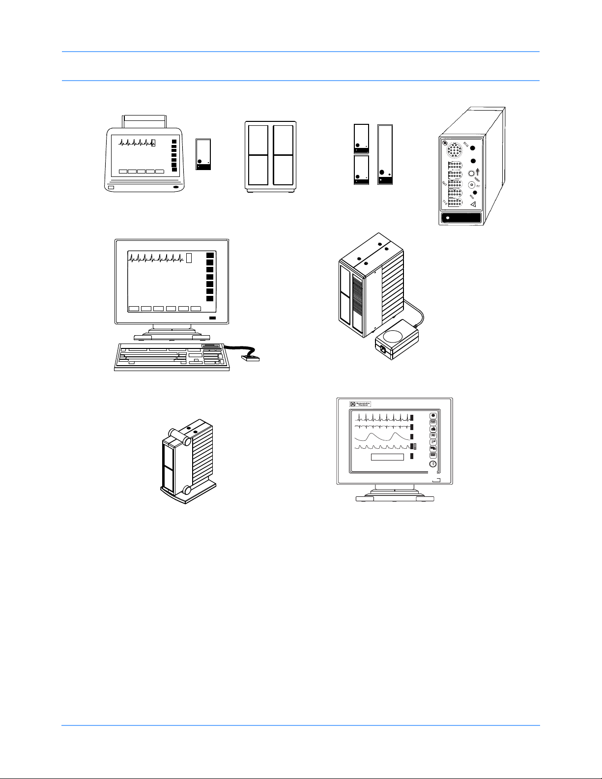
System Introduction and Network Basics
Modules
90491 Module
Housing
module
90367 Ultraview 1030 Monitor
90369 Ultraview 1050 Monitor
90385 UCW
®
Monitor
90364 Ultraview 1600 Monitor
90387 Ultraview 1700 Monitor
90363 Ultraview 1500 Monitor
a
d
u
l
t
N
I
B
P
N
I
B
P
S
p
O
2
P1
-
2
P
3-4
CO
h
lo
2
h
lo
1
2
90496 Ultraview
Command Module
90499 Module Housing
Color Display, CRT or flat panel
with Touchscreen
Only
Caution:
US Federal law restricts the devices documented herein to sale by, or on the order of, a
Rx
physician.
Figure 1-1: Ultraview Care Network monitor family
15:55 110/ 68( 84) mmHg HR= 69 (ECG)
16:54 115/ 68( 77) mmHg HR= 69 (ECG)
16:55 113/ 55( 88) mmHg HR= 69 (ECG)
16:56 108/ 56( 82) mmHg HR= 69 (ECG)
16:57 116/ 62( 83) mmHg HR= 69 (ECG)
♥ II MON
E
?
ST= 0.08
A=0
HELP
C
ROW 5
120
G
69
40
MONITOR
SETUP
V3
E
ST=-0.16
R
C
X
G
SPECIAL
FUNCTIONS
RA-LA
R
E
*
TONE RESET
S
ALM SUSPEND
30
P
20
0
RECORD
S
*
P
68
bpm
O
100
2
85
%
97
PREVIOUS
MENUS
( 83)
N
I
m
116
LAST BP=
NORMAL
m
B
SCREEN
16:57
150
H
P
S
02/21
100
62
g
21 FEB 1994
Ultraview Care Network Operations Manual 1-2
Page 17

System Introduction and Network Basics
System Basics
Ultraview Care Network monitors provide a consistent operator interface across all bedside and central
monitoring environments. Monitors installed on a network provide access from monitor to monitor and enable
you to control the remote data.
Networked monitors enable you to view waveforms and numeric values of patient parameters, review vital sign
and ECG arrhythmia and ST history, and record patient data automatically during alarm events. Refer to
Network Basics on page 1-10 for more information.
• Central stations display patient specific parameters, remote alarms, and alarm limits that are based on the
setting of the bedside as determined by the primary caregiver. Refer to Central Monitors on page 6-3 for
detailed information on the system capabilities.
• The Remote View feature enables you to monitor two patients simultaneously. Remote views of
waveforms and numerics are nearly identical in display and function to the parameter at the originating
monitor. Alarms, trends, menu keys, and recordings are accessible through a Remote View. Refer to
Viewing Remote Parameters on page 1-11 and Alarms on page 2-3 for more information.
• The Full Bed Review feature enables you to view multiple parameters on a UCW and Ultraview 1700
bedside monitor from any other bedside or central monitor on the network. Refer to Full Bed Review —
UCW and Ultraview 1700 Only on page 1-13 for more information.
• The Alarm Watch feature notifies you when an alarm occurs on any other monitor on the network. Refer to
Alarm Watch on page 2-8 for more information.
• Vital signs trending provides minute-by-minute recording of parameter data for review and for
documentation in the patient record. You select the format and interval for trending. Refer to Trends on
page 26-3.
• Optional calculations features provide automatic calculation and trending of advanced clinical variables
including hemodynamic, renal, oxygenation, ventilation calculations, and drug dosage. Refer to
Calculations on page 25-5.
Ultraview Care Network Operations Manual 1-3
Page 18

System Introduction and Network Basics
Monitor Basics
Ultraview Care Network monitors use modules to monitor various clinical parameters. For example:
• Electrocardiograph (ECG). Refer to ECG on page 8-3.
• Noninvasive Blood Pressure (NIBP). Refer to NIBP on page 13-3.
• Cardiac Output (CO). Refer to Cardiac Output on page 19-3.
Remote module housing units may be used with Ultraview Care Network monitors to house additional
modules. The 90385 Universal Clinical Workstation (UCW), 90363 Ultraview 1500, 90364 Ultraview 1600, and
90387 Ultraview 1700 monitors must use a remote module housing unit to house any of its modules.
• Each 90499 module housing holds up to two modules.
• Each 90491 module housing holds up to four modules.
An external power supply is needed whenever a module housing is used. A separate power supply is required
for the 90491 and 90499 module housing.
Warning:
Due to the potential for electromagnetic interference, portable communication transmitters and
cellular phones should not be operated within 1.07 meters (3.5 feet) of the patient, patient leads, or
associated patient monitoring equipment.
Note:
All references to the Universal Clinical Workstation or UCW include the Universal Clinical WorkstationIndependent Display (UCW-ID), and all the available features of the UCW-ID.
Power Failure
Warning:
• In the case of a power failure, the remote module housing (90491 or 90499) provides +5 volts of
power to maintain data integrity.
• If the power is interrupted to the remote module housing but not to the monitor, the module will
remain active and the following will occur:
- Waveforms will go flat (as if the patient has no vital signs) or will be totally lost.
- Parameter values will go to the minimum limit or ??? (except for non-invasive pressure,
which will display the last value before the power failure).
- Alarms may sound for low limit violations or for conditions such as Asystole, Leads Off,
Loss of Signal, or Adapter Disconnected.
• If any of the above conditions occur, check to determine whether or not power has been
interrupted to the remote module housing and re-establish AC power.
• Do not allow the Ultraview 1600, Ultraview 1700, or the 90499 module housing to be left turned
ON without power applied for long periods of time or the memory backup batteries will be
depleted.
Ultraview Care Network Operations Manual 1-4
Page 19

System Introduction and Network Basics
Modules are designed with default settings for alarms and various other parameter settings (for example, NIBP
reading frequency) which you may adjust to meet the needs of your patients. When events occur that might
cause the selected limits or values to return to the monitor default settings, the monitor may display a CHECK
SETUP key in the ECG zone combined with a low priority alarm tone (refer to Setting Alarm Limits on page 2-4
for details on alarm priorities). To cancel the message and the alarm, simply touch the CHECK SETUP key on
the screen.
The following describes the events that will cause the CHECK SETUP key to appear.
Event Reason
Any time you power ON a monitor, all
parameters are reset to their default values or
Monitor power ON
When you insert an
ECG module
to the values set the last time the monitor was
in use. It is very important to review the
parameter limits and/or their values and adjust
them appropriately for the current patient.
Because the module values will come up with
default settings, it is important to review and
reset the limits and/or values for that particular
patient.
An error is detected
and the monitor
resets
Note:
Check Setup is an optional feature on the ECG channel. Contact your system administrator if your system
does not have this feature.
The monitor has detected an error that cannot
be corrected through other means.
Ultraview Care Network Operations Manual 1-5
Page 20
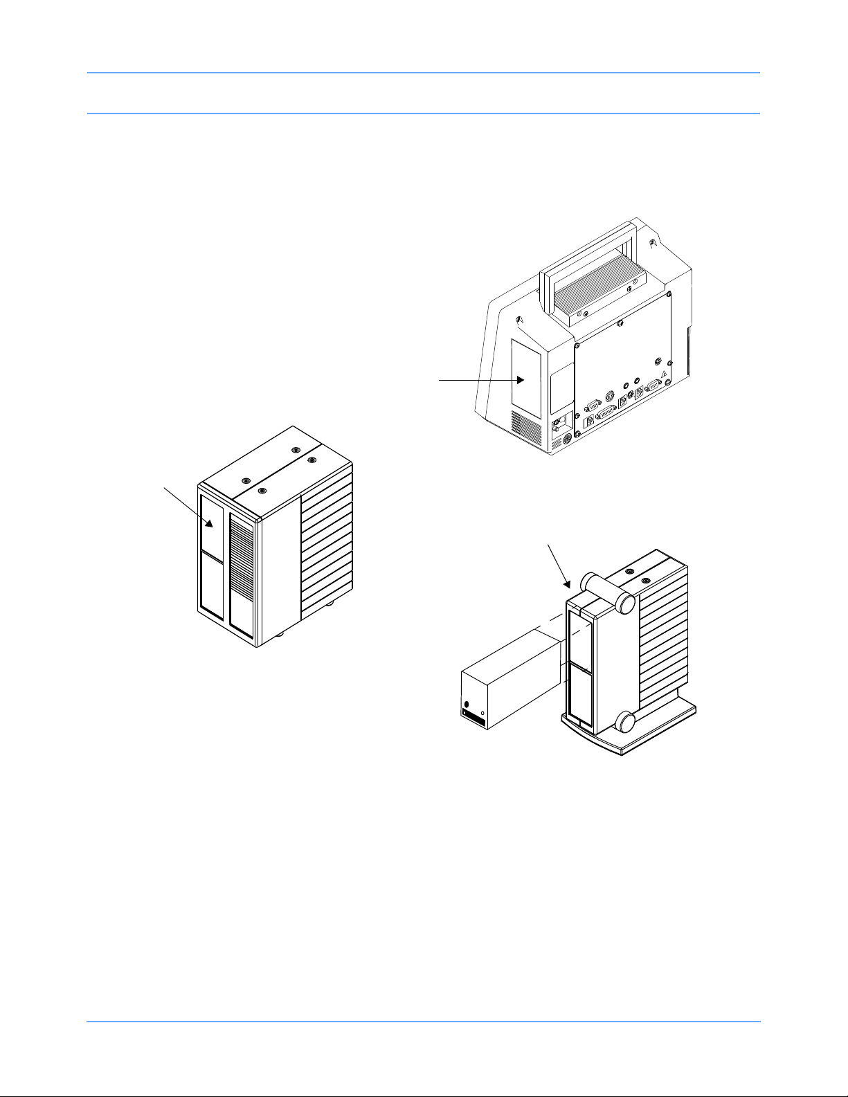
System Introduction and Network Basics
remote module housing
Ultraview 1030/1050
right side view
patient
module
slot
90499 Module Housing
patient
module
slot
Ultraview 1600 and
Ultraview 1700 Monitors
Inserting Modules
Insert a module into the bedside monitor (Ultraview 1030/1050) or into the remote module housing as shown
below.
Figure 1-2: Ultraview Care Network module insertion
Patient Preparation
To prepare the patient for monitoring, attach the patient cable, and connect the patient cable to the module.
Touch a parameter key, then touch the menu keys as needed to set up monitoring for a specific parameter.
Ultraview Care Network Operations Manual 1-6
Page 21
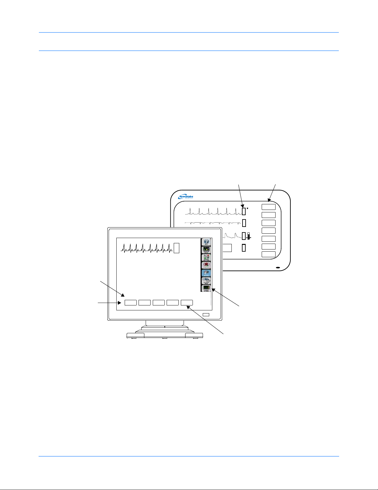
System Introduction and Network Basics
monitor
keys (Icons)
monitor
keys
parameter
keys
menu keys
menu
line
message
area
PRINTER
CONTROLS
11:32
11:33
11:34
11:35
11:36
110/ 69( 84)
113/ 73( 88)
113/ 69( 84)
82/ 51( 64)
108/ 67( 83)
TEMP
34.7
Using the Monitor Screen
Ultraview Care Network monitors employ touchscreen technology for interaction with the system. To activate a
menu or parameter key, simply touch the key on the screen.
Using the Screen Keys
The Ultraview Care Network monitors use keys on the screen to execute monitor functions. The monitor keys
are located to the far right side of the screen and have standard functions regardless of the parameter being
monitored. The menu keys appear along the bottom of the screen as menu items. The (physiological)
parameter keys appear next to the parameter display. Some monitors (for example, the UCW) display these
keys pictorially as icons, but the key names and functionality are the same for all Ultraview Care Network
monitors.
Figure 1-3: Screen keys
Ultraview Care Network Operations Manual 1-7
Page 22

System Introduction and Network Basics
Menu and Parameter Keys
The menu and parameter keys appear on the monitor screen as displayed in Figure 1-3.
• Touch a parameter key to display a set of menu keys for that parameter
• Touch a menu key to control a monitoring function, for example, ALARM LIMITS
Keys that are currently active appear in bold lettering. Inactive keys appear in dim lettering. When you touch an
inactive key an error tone will sound.
Touch the HELP key, and then the key in question, to display a description of its function in the system
message area above the menu line.
To obtain help about a menu key:
• Touch HELP.
• Touch the desired menu key.
Touch the MONITOR SETUP key to display a menu that enables you to adjust tones, enter patient data,
modify the screen format, set time and date, adjust brightness, determine battery status (Ultraview 1030/1050
only), and specify printing characteristics.
To customize your monitor:
• Touch MONITOR SETUP.
• Select any menu key.
The UCW and Ultraview 1700 enable you to display a digital clock, stopwatch, or timer in the lower right corner
of the screen. Touch the clock to display the clock menu. The Ultraview 1030, 1050, 1500, and 1600 monitors
display a digital clock at the bottom right of the screen. Refer to Bedside/Transport Monitors on page 5-3 and
Central Monitors on page 6-3 for a detailed explanation of the functions that apply to your system.
Touch the SPECIAL FUNCTIONS key to display a menu that enables you to view remote parameters, activate
automatic notification of remote alarms, view trends of vital sign data and clinical and drug calculations, and
use other optional network applications.
To activate additional functions:
• Touch SPECIAL FUNCTIONS.
• Select any menu key.
When you touch the TONE RESET/ALM SUSPEND key once during an alarm condition it will silence the
alarms for 45 seconds at the unit where the key was touched (bedside or central). Touching the key again
during the initial 45-second suspension will silence the alarms for three minutes at the bedside only. Refer to
Alarms on page 2-3 for more details.
Ultraview Care Network Operations Manual 1-8
Page 23

System Introduction and Network Basics
To temporarily silence alarm tones:
• Touch TONE RESET/ALM SUSPEND once to silence for 45 seconds.
• Touch TONE RESET/ALM SUSPEND again (within 45 seconds) to suspend alarms for
three minutes (bedside only).
You may use either a system printer or a printer module for recording patient data. Recordings of monitored
data can be generated by touching the RECORD key and then touching up to four flashing parameter keys
(depending on the printer capacity). Refer to Printing on page 4-5 for more details.
To record a parameter:
• Touch RECORD once.
• Select up to four flashing parameter keys.
Touch the PREVIOUS MENU key to move back one menu level. From the Main menu level, touch PREVIOUS
MENU to remove the current menu from the display and close the application window.
Touch the NORMAL SCREEN key to close any active application window, and its menus, or to return to the
basic display.
To change the screen display:
• Touch PREVIOUS MENU to return to last menu.
• Touch NORMAL SCREEN to remove the menu from the screen.
Using the Keyboard
A keyboard can be used for certain applications like Calculations and Admit/Discharge. An on-screen
keyboard is provided for all local applications, but you may also use an external keyboard. Refer to Using the
On-Screen Keyboard on page 3-4 for keyboard displays. Use the arrow keys and TAB key on the keyboard to
move within an application window.
Using the Mouse
If your system is equipped with a mouse it may be used with selected functions in lieu of the keyboard or
touchscreen. Click the left mouse button on a menu key to activate the key.
Ultraview Care Network Operations Manual 1-9
Page 24
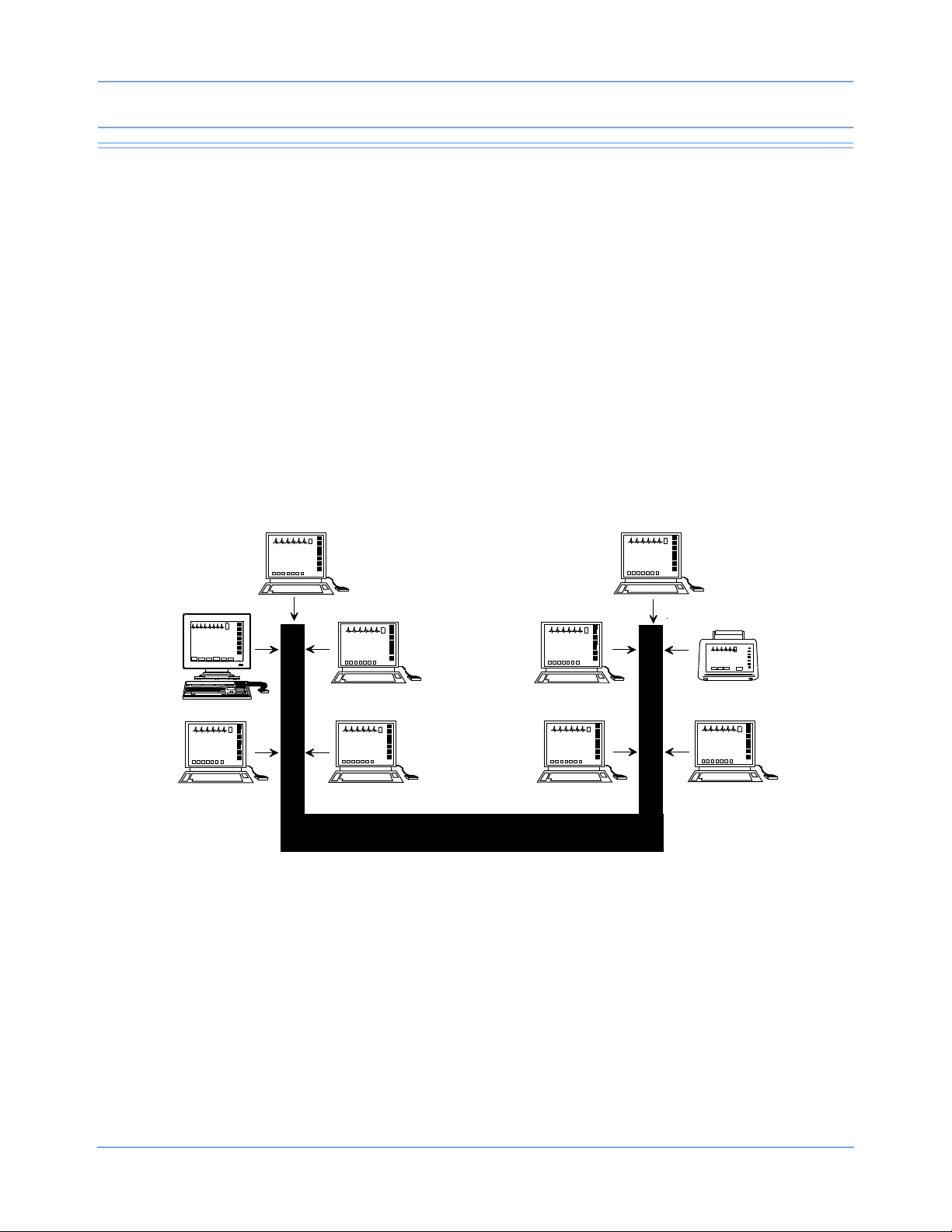
System Introduction and Network Basics
Subnet #1
Intensive Care Unit
Subnet #2
Emergency Room
NETWORK
Network Basics
To aid in understanding the concept of a network operation, consider your need to communicate between beds
in a single care unit. While you are in the care unit at a bedside monitor, you can view parameter waveforms
from another bed and control those parameters just as if you were at that remote bedside.
Advanced networking allows remote access and interaction with Clinical and Drug Calculations, Tabular
Trends, Graphic Trends, and parameters from remote beds. Standard networking allows the remote viewing of
single parameters from bedside to bedside, and bedside to central. The Full Bed Review feature on the UCW
and Ultraview 1700 allows remote viewing of the entire bedside monitor.
If you need to review information from another unit on the network, you can do so by specifying the unit as well
as the bed. For example, if you have a need for frequent communication between your care unit and another
care unit, those units would be designated as subnets on your networked system. This identification typically
appears on the keys in the appropriate menus.
The following figure illustrates a possible network configuration.
Although the presence of the network is invisible to you as you operate any monitor on the system, decisions
were made during installation to configure the system according to your hospital’s specifications. Typically,
hospitals designate a system administrator for this task. This manual directs you to refer questions to that
individual where system operation may differ according to the decisions made by your hospital.
Ultraview Care Network Operations Manual 1-10
Figure 1-4: Network configuration
Page 25

System Introduction and Network Basics
Watching Alarms Remotely — Alarm Watch
With the network Alarm Watch function enabled you will be notified of all alarms at all monitors. Once a monitor
has been set up to Alarm Watch a bed, any alarm from that bed is reported.
Warning:
• The Alarm Watch function is not automatically enabled. You must first select the bed that the
central or bedside monitor should Alarm Watch.
• Alarm conditions for parameters not currently displayed on the central monitor will only be
reported at a central monitor when Alarm Watch is enabled at the central monitor.
Refer to Alarm Watch on page 2-8 for more information.
To enable Alarm Watch:
• Touch SPECIAL FUNCTIONS.
• Touch ALARM WATCH.
• Select a bed or a subnet.
• If you selected a subnet, then select a bed.
• Touch ALARM WATCH.
Viewing Remote Parameters
Each parameter on a bedside monitor can be independently viewed (Remote View) on any other bedside or
central monitor on the network. Remote views of parameters can be identical in display and function to the
local bedside, with the addition of the patient name and bed identification label.
If enabled by your system administrator alarms and menu keys operate the same at the remote monitor as
they do at the local bedside.
Bedside monitors can have parameters remotely viewed by up to 16 other devices.
Note:
Your network protocol may not enable you to make remote alarm limit changes or to remotely control a
parameter. If you have a question regarding this function, ask your system administrator.
To view remote parameters from a bedside monitor:
• Touch SPECIAL FUNCTIONS.
• Touch REMOTE VIEW.
• Select a bed or a subnet.
• If you selected a subnet, then select a bed.
• Select desired parameter.
Ultraview Care Network Operations Manual 1-11
Page 26
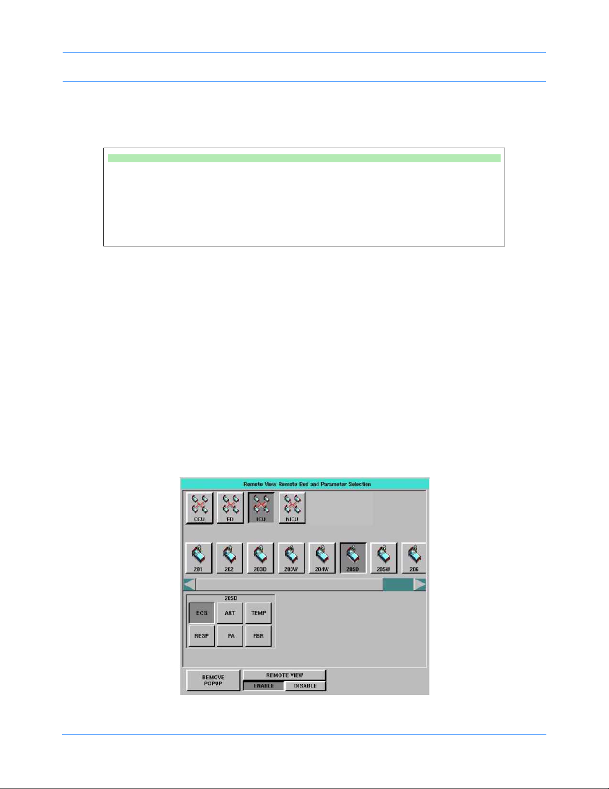
System Introduction and Network Basics
Remotely viewed parameters occupy the lowest zone on the screen of a bedside monitor. On the central
monitor each remote parameter is assigned a specific display position. Every Remote View zone is separated
from other zones by a dividing line.
To view remote parameters from a central monitor:
• Touch MONITOR SETUP.
• Touch SCREEN FORMAT.
• Select the destination display zone.
• Select a subnet or bed as appropriate.
• Select a parameter and color.
When a bedside monitor is set up to remotely view a parameter from another bedside, a one-second advisory
tone sounds at the onset of the alarm condition. The remote alarm tones must be active at that bedside
monitor.
Arrhythmia and ST segment review data can also be viewed from remote monitors if optional Arrhythmia and
ST segment analysis software is part of your system.
Warning:
Remote View and Alarm Watch are mutually exclusive functions on the bedside monitor. Selecting
to remotely view a parameter at a bedside inactivates the Alarm Watch function at that monitor.
When you need to control or continually observe a parameter from a remote monitor, use the Remote View
function. When you wish to have remote notification of alarms, use the Alarm Watch function.
Note:
Your network protocol may not allow you to control remotely viewed parameters. If you have a question
regarding this function, ask your system administrator.
Figure 1-5: Remote View (UCW/Ultraview 1700)
Ultraview Care Network Operations Manual 1-12
Page 27

System Introduction and Network Basics
Full Bed Review — UCW and Ultraview 1700 Only
The Full Bed Review (FBR) key allows you to view several parameters from another monitor at your bedside or
central station monitor. The monitor at which the Full Bed Review is enabled will display all available
parameters from the remote monitor within the limitations of the capabilities of the displaying monitor.
Whenever a bedside or central monitor is displaying another monitor’s data, an FBR key appears in the lower
left corner if no menus are displayed. Full Bed Review can be activated by touching this FBR key, then
selecting one of the flashing parameter keys. If the monitor is not displaying another monitor’s data, Full Bed
Review can be activated by touching the FBR key that follows the last parameter icon for the selected bed.
If more parameters are available from the remote bedside than FBR can display, keys for these additional
parameters are displayed as numeric keys along the bottom of the screen. Selecting any of these numeric
keys causes the selected parameter to replace the lowest parameter.
The parameter keys displayed by FBR are interactive. To access the controls for a parameter, touch that
parameter’s key. Remote review of trended or calculated data for the selected monitor is available by touching
the TRENDS/CALCS key found in the Special Functions menu.
Note:
Full Bed Review displays a single ECG lead if the remote bedside is configured to display ECG data using
the Full View or Split View format.
To deactivate the FBR feature, touch NORMAL SCREEN.
To activate Full Bed Review at a bedside monitor when a remote view is not
displayed:
• Touch SPECIAL FUNCTIONS.
• Touch REMOTE VIEW.
• Select one of the subnet icons, then select a bed icon.
• Touch the FBR key displayed after the last parameter icon for that bed.
-OR-
• Select any parameter icon, then perform the steps in the following Quick Start.
To activate Full Bed Review when a remote parameter is already displayed:
• Touch NORMAL SCREEN, if needed, to display all parameters.
• Touch FBR displayed in the lower left corner of the monitor.
• Touch the flashing parameter key of the selected remote bed.
Ultraview Care Network Operations Manual 1-13
Page 28

System Introduction and Network Basics
To activate Full Bed Review at a central monitor without parameters already
displayed:
• Touch MONITOR SETUP.
• Touch SCREEN FORMAT.
• Select one of the subnet icons, then select a bed icon.
• Touch the FBR key displayed after the last parameter icon for that bed.
-OR-
• Select any parameter icon, and select a display zone to assign that parameter to that
display zone.
• Follow the steps in the previous Quick Start.
To deactivate the Full Bed Review:
• Touch NORMAL SCREEN.
Reviewing Remote Trends
Retrospective vital sign review through either graphic or tabular trends provides minute-by-minute access to
data from any monitor on the network.
To display a trend from a remote monitor:
• Touch SPECIAL FUNCTIONS.
• Touch REMOTE TRENDS/CALCS.
• Select a bed or a subnet.
• If you selected a subnet, then select a bed.
• Touch GRAPHIC TRENDS or TABULAR TRENDS.
Ultraview Care Network Operations Manual 1-14
Page 29
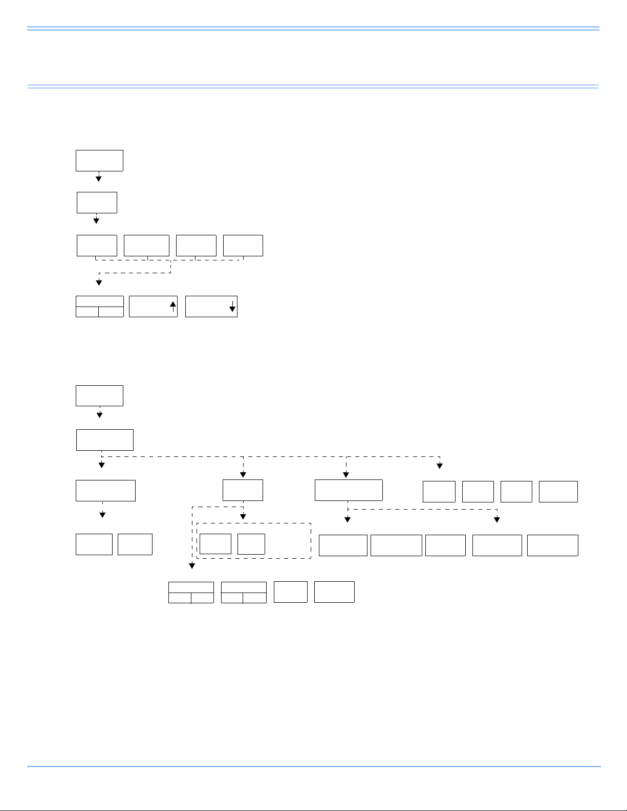
Alarms
Adjusting Alarm Tones
TONE
OFF
MONITOR
SETUP
TONES
REMOTE
ALARMS
ALARM
WATCH
KEY
TONE
LOCAL
ALARMS
VOLUME VOLUME
MONITOR
SETUP
RECORDER
CONFIG.
RECORDING
DURATION
ALARM
PAR AMS
MORE
Setting Up Automatic Alarm Recordings
MONITOR SETUP
MONITOR SETUP - Select type of tone to change
MONITOR SETUP - LOCAL ALARM TONE
MONITOR SETUP
RECORDER CONFIGURATION
Select parameters which require alarm recordings from BED X
RECORDING
DESTINATION
NETWORK BOTH
ALARM RECORDINGS TO
THIS
MONITOR
12 SEC 20 SEC
On Central only - Select Bed
BED X
...
Select duration for recordings
initiated from this monitor
1
2
4
VITALS
SETUP
Number of recorder channels
THIS
NETWORK
MONITOR
OTHER RECORDINGS TO
ON
ECG
ON OFF
RESP
ON OFF
...
Directory of Keys
Note:
Based on features purchased, more or fewer keys may appear here than on your menu screens.
Ultraview Care Network Operations Manual 2-1
Page 30
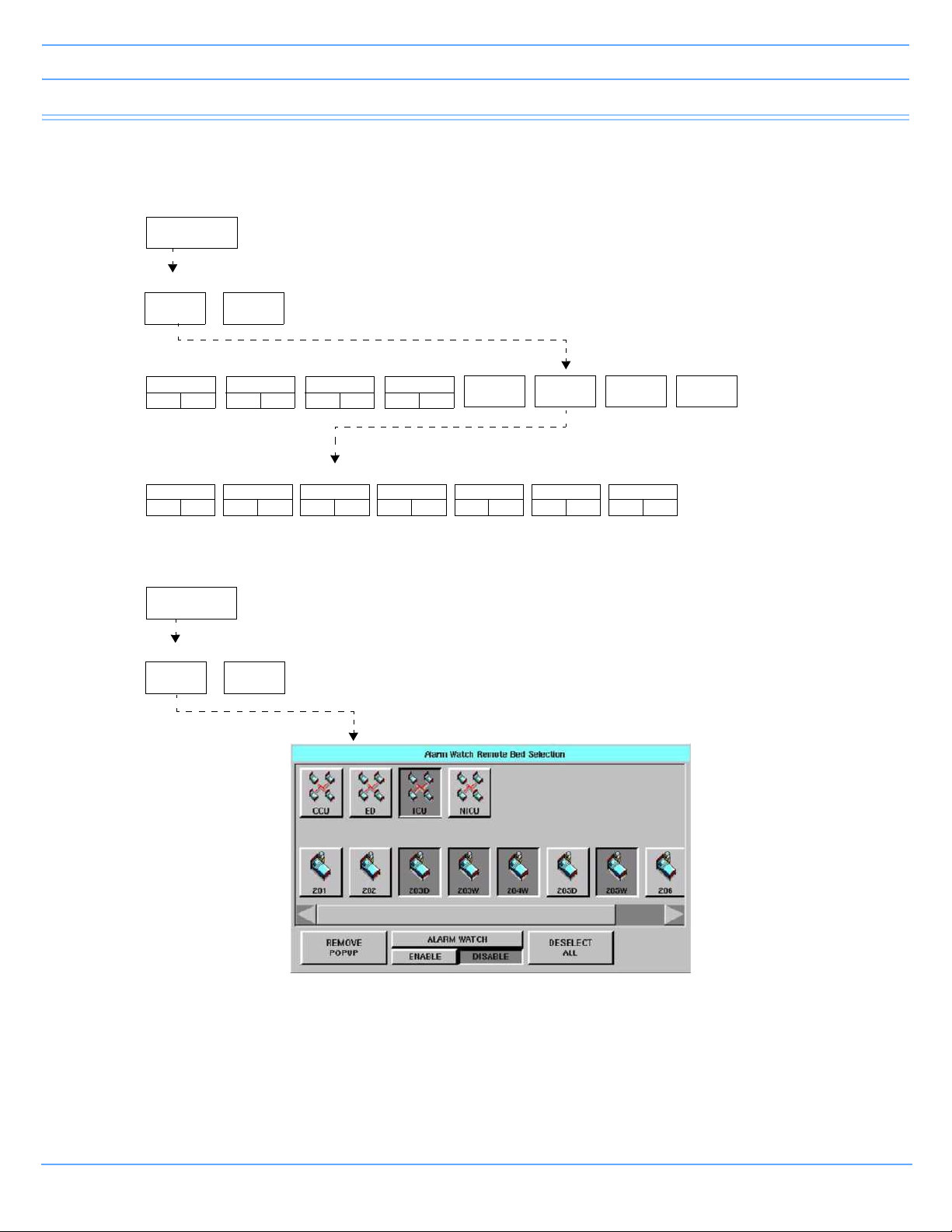
Directory of Keys
SPECIAL
FUNCTIONS
ALARM
WATCH
RV/AW
OFF
NET 02 NET 03 NET 04 MORE
SPECIAL FUNCTIONS
ALARM WATCH - Select bed(s) for ALARM WATCH
ALARM WATCH - Select bed(s) for ALARM WATCH in subnet NET03
1001
ON OFF
1002
ON OFF
1003
ON OFF
1004
ON OFF
3001
ON OFF
3002
ON OFF
3003
ON OFF
3004
ON OFF
3005
ON OFF
3006
ON OFF
3006
ON OFF
Setting Up Alarm Watch (1030/1050/1500/1600)
Setting Up Alarm Watch (UCW/Ultraview 1700)
SPECIAL
FUNCTIONS
ALARM
WATCH
RV/AW
OFF
SPECIAL FUNCTIONS
Alarms
Note:
Based on features purchased, more or fewer keys may appear here than on your menu screens.
Ultraview Care Network Operations Manual 2-2
Page 31

Alarms
Contents
Overview. . . . . . . . . . . . . . . . . . . . . . . . . . . . . . . . . . . . . . . . . . . . . . . . . . . . . . . . . . . . . . . . . . . . . . . . . . . . . 3
Default Alarm Limits . . . . . . . . . . . . . . . . . . . . . . . . . . . . . . . . . . . . . . . . . . . . . . . . . . . . . . . . . . . . . . . . . . . . 3
Setting Alarm Limits . . . . . . . . . . . . . . . . . . . . . . . . . . . . . . . . . . . . . . . . . . . . . . . . . . . . . . . . . . . . . . . . . . . . 4
Identifying Alarm Levels . . . . . . . . . . . . . . . . . . . . . . . . . . . . . . . . . . . . . . . . . . . . . . . . . . . . . . . . . . . . . . . . . 4
Adjusting Alarm Tones/Key Tones . . . . . . . . . . . . . . . . . . . . . . . . . . . . . . . . . . . . . . . . . . . . . . . . . . . . . . . . . 6
Controlling Alarms via the TONE RESET/ALM SUSPEND Key. . . . . . . . . . . . . . . . . . . . . . . . . . . . . . . . . . . 7
Alarm Watch . . . . . . . . . . . . . . . . . . . . . . . . . . . . . . . . . . . . . . . . . . . . . . . . . . . . . . . . . . . . . . . . . . . . . . . . . . 8
Automatic Recording of an Alarm . . . . . . . . . . . . . . . . . . . . . . . . . . . . . . . . . . . . . . . . . . . . . . . . . . . . . . . . . 11
Alarms Troubleshooting Guide . . . . . . . . . . . . . . . . . . . . . . . . . . . . . . . . . . . . . . . . . . . . . . . . . . . . . . . . . . . 12
Overview
This chapter describes how to use the Alarm Watch feature, set alarm limits, silence and suspend alarms, set
alarm tones, and specify parameters for automatic alarm recordings.
When a parameter goes into alarm on a local bedside monitor, the corresponding parameter key flashes on the
screen, an alarm message is displayed, and an alarm tone sounds (unless tones are disabled). You can also
choose to automatically record the parameter in alarm on a bedside or network printer. Networked monitors
enable you to monitor alarm conditions at both the central and bedside monitors simultaneously through the
Alarm Watch feature.
Warning:
Alarm conditions for which you want to be alerted must be set to ON or enabled at the location
where you want to be alerted, bedside or central. You can enable them from the local bed, remote
bed, or central.
Note:
Define your own default settings for alarm limits, alarm priorities, recordings, and other attributes with the
Module Configuration Manager feature. Refer to Module Configuration Manager on page 7-5 for further
details.
Default Alarm Limits
Factory default alarm limit settings are activated whenever the monitor is powered ON, whenever a module is
inserted, or when a parameter is enabled. You can modify these settings to meet your own protocols.
Refer to the Alarm section of the appropriate parameter chapter in this manual for details concerning setting or
adjusting alarm limits for a specific parameter.
Ultraview Care Network Operations Manual 2-3
Page 32

Alarms
Setting Alarm Limits
You can change parameter alarm limits by using the parameter's Alarm Limits menu. The steps to the left
illustrate the minimum procedure used to adjust high and low alarm limits for a parameter.
Note:
• Parameters may contain additional alarm limit features not listed here. Read the specific parameter
chapter (for example, ECG or NIBP) in this manual for details.
• To set fetal alert limits, please refer to Fetal Monitoring on page 15-3 for further details.
To set alarm limits:
• Touch a parameter key (ECG, TEMP, etc.).
• Touch ALARM LIMITS.
• Ensure ALARMS ON is set.
• Select HI = or LO =.
• Use arrow keys to adjust.
Identifying Alarm Levels
Alarm conditions are visually and audibly prioritized as high, medium, or low.
Table 1: Bedside Alarms
Priority Tone Type* Visual Tone Duration
Until the alarm condition is
resolved, the alarm is
suspended, or the tone is
reset
Until the alarm condition is
resolved, the alarm is
suspended, or the tone is
reset
Until the alarm condition is
resolved, the alarm is
suspended, or the tone is
reset
High
Medium
Low
Continuous tone, or 2
bursts of 5 tones every
15 seconds
Intermittent tone (one
second ON, one
second OFF), or burst
of 3 tones every
30 seconds
Intermittent tone (one
second ON, four
seconds OFF), or 1
tone every 30 seconds
Flashing key;
message appears in
red on color monitors
Flashing key;
message appears in
yellow on color
monitors
Flashing key;
message appears in
yellow on color
monitors
* The repetition rate for the tone bursts on the High, Medium, and Low levels may be adjusted for all
monitors by your system administrator.
Ultraview Care Network Operations Manual 2-4
Page 33

Alarms
Warning:
Parameters shown in the ECG waveform zone in Enhanced Vital Signs mode do not alarm at the
central station. Only parameters set via the Alarm Watch mode will alarm as set up by the system
administrator.
Table 2: Alarm Watch and Remote View Alarms
Priority Tone Type* Visual Tone Duration
Central
continuous tone, or 2 bursts
High
Medium
Low
* The repetition rate for the tone bursts on the High, Medium, and Low levels can be adjusted for all
monitors by your system administrator.
of 5 tones every 15 seconds
Bedside
one single tone
Central
intermittent tone
(one second ON,
one second OFF), or burst
of tones every 30 seconds
Bedside
one single tone
Central
intermittent tone
(one second ON,
four seconds OFF), or one
tone every 30 seconds
Bedside
one single tone
Flashing key;
message appears in
red on color monitors
Flashing key;
message appears in
yellow on color
monitors
Flashing key;
message appears in
yellow on color
monitors
Central
until the alarm condition is
resolved or the tone is
reset
Bedside
one second
Central
until the alarm condition is
resolved or the tone is
reset
Bedside
one second
Central
until the alarm condition is
resolved or the tone is
reset
Bedside
one second
Ultraview Care Network Operations Manual 2-5
Page 34

Alarms
Adjusting Alarm Tones/Key Tones
You can turn the alarm tone ON or OFF and adjust the tone volume for local alarms, Remote View alarms, or
Alarm Watch alarms. While you are adjusting tone volume, a tone sounds briefly as an example of the new
level.
Alarm tones refer to the sound associated with an alarm condition. Key tones sound each time you touch a
screen key.
Volume adjustments affect only the monitor where the adjustment is made. The tone volume of an alarm
notification at a remote monitor must be adjusted at that monitor. It cannot be adjusted remotely. A visual alarm
notification is displayed until the condition is resolved, even if you disable the alarm tones at that monitor.
Alarm Watch tones sound when the Alarm Watch feature is active and an alarm condition exists on a watched
monitor. The Alarm Watch feature must be enabled via the Special Functions menu for the Alarm Watch tone
to sound.
The Remote View alarm tone only sounds when a remotely viewed parameter goes into alarm.
Warning:
Disabling alarm tones via Monitor Setup at a bedside or at a central monitor eliminates alarm tones
for all alarm conditions at that monitor, even in the case of life-threatening events.
To set local alarm tones or key tones:
• Touch MONITOR SETUP.
• Touch TONES.
• Select LOCAL ALARMS or KEY TONE.
• Select TONES ON.
•Use VOLUME and VOLUME keys to adjust.
To set alarm watch tones or remote view tones:
• Touch MONITOR SETUP.
• Touch TONES.
• Select ALARM WATCH or REMOTE ALARMS.
• Select TONES ON.
•Use VOLUME and VOLUME keys to adjust.
Ultraview Care Network Operations Manual 2-6
Page 35

Alarms
Controlling Alarms via the TONE RESET/ALM SUSPEND Key
During an Alarm Condition
If you touch TONE RESET/ALM SUSPEND once at a monitor during an alarm condition:
• The alarm tone is silenced at that monitor for 45 seconds, but the alarm tone continues to sound at other
monitors. If the alarm condition continues, the alarm tone resumes at that monitor at the end of the
45-second period. If another parameter goes into alarm during this period, or if the initial condition ends
and then begins again, the alarm tone will again sound at that monitor.
• The message ALARM TONES SUSPENDED FOR 45 SECONDS is displayed only on that monitor.
• All flashing parameter keys continue to flash.
At a bedside monitor, when you touch the TONE RESET/ALM SUSPEND again within 45 seconds:
• All alarms and alarm recordings are suspended for three minutes. No alarms sound for any reason during
this period, and no new alarm recordings are produced.
Note:
The ALM SUSPEND feature is only available at bedside monitors. If this feature has been disabled (set to
OFF), the TONE RESET/ALM SUSPEND key does not suspend alarms.
• A message is displayed to indicate that all alarms are suspended.
• Trend data may not be collected. This feature can be enabled or disabled only by your system
administrator.
To silence an alarm tone for 45 seconds at any monitor, touch the TONE RESET/
ALM SUSPEND key once.
To resume alarm tones at a central monitor, touch the TONE RESET/ALM
SUSPEND key again.
To suspend all alarms at a bedside monitor for three minutes, touch the TONE
RESET/ALM SUSPEND key again within 45 seconds.
Note: If alarms resume the second time the key is touched, your bedside monitor
may be configured differently for this feature. Contact your system administrator
for details.
Normal alarm operation can be resumed within the three-minute time period by touching the TONE RESET/
ALM SUSPEND or RESUME ALARMS key again.
Note:
The ALM SUSPEND key is relabeled as RESUME ALARMS after the first key touch.
Ultraview Care Network Operations Manual 2-7
Page 36

Alarms
To resume normal alarm operation at a bedside monitor within the three-minute
period, touch the TONE RESET/ALM SUSPEND or RESUME ALARMS
(Ultraview 1030, 1050, 1500, and 1600 monitors) key again.
In the Absence of an Alarm Condition
Note:
The TONE RESET/ALM SUSPEND key is relabeled as ALARM SUSPEND after the first key touch.
Touching the TONE RESET/ALM SUSPEND key once when no parameters are in an alarm condition
suspends the alarms at the bedside monitor. (Refer to During an Alarm Condition on page 2-7.)
To resume alarms at a bedside monitor, touch the TONE RESET/ALM SUSPEND key again.
Note:
You cannot suspend alarms from a central monitor. However, you can silence alarm tones for 45 seconds.
Touching this key has no effect if it is touched at the central monitor when no alarm is sounding.
To suspend alarms at a bedside monitor when no alarm is sounding, touch the
TONE RESET/ALM SUSPEND key once.
Alarm Watch
With the network Alarm Watch feature, you can be notified at a local bedside or central monitor of all alarms
from a remote bed. The Alarm Watch feature defaults to its last setting when the monitor is turned ON. The
local monitor displays the message ALARM WATCH ON when the Alarm Watch feature for a remote bed is
active. On a central monitor, the message AW OFF also displays for each bed not selected for Alarm Watch.
Note:
A central monitor can be configured with the Central Alarm Watch Manager to automatically Alarm Watch
every bed it is currently monitoring. Contact your system administrator about this feature.
Refer to Viewing Remote Parameters on page 1-11 for more information. The listed limits for the number of
devices that can remotely view a monitor apply to Alarm Watch-initiated remote views.
When a parameter from a monitor that is under Alarm Watch goes into alarm, a message such as ALARM
WATCH – BED 28 ECG CHANNEL IN ALARM displays on the message line of the alarm-watching monitor. A
one-time advisory tone sounds at the watching bedside or central monitor. The corresponding waveform
appears in the lowest zone on the screen of the alarm-watching monitor, unless:
• another alarm-watched parameter is in alarm and its waveform already occupies that zone at the watching
monitor,
-OR-
• a parameter is displayed in the lowest zone of the monitor and its parameter key has been activated
displaying a menu.
Ultraview Care Network Operations Manual 2-8
Page 37

Alarms
When a waveform for an Alarm Watch parameter in alarm displays, the appropriate tone sounds at the bedside
(once) and at the central monitors for the duration of the alarm.
Only one Alarm Watch waveform can be viewed at a time. When subsequent, concurrent alarms occur for one
patient or other patients on Alarm Watch, a message displays and a one-second advisory tone sounds.
Remember to enable Alarm Watch tones in the Monitor Setup menu to produce audible alarms.
If multiple alarms occur simultaneously, the messages displayed cycle from one to another every three
seconds (up to a maximum of ten alarms) until all alarm conditions are resolved, or until you disable alarms at
either the local monitor (through Remote View) or the remote monitor.
Warning:
• Using the Alarm Watch feature, you can watch for alarms from 32 other monitors. However,
more than ten remote alarms cannot be reported simultaneously to any monitor using the Alarm
Watch feature.
• Remote View and Alarm Watch are mutually exclusive features on bedside monitors. If you
select to Remote View a parameter the Alarm Watch feature at that monitor is inactivated.
To resume Alarm Watch, touch the ALARM WATCH or ALARM WATCH ENABLE (on the UCW and Ultraview
1700) key. Alarm Watch is resumed for all previously selected patients. You can also add patients for Alarm
Watch. The ALARM WATCH ON message displays in the message zone whenever one or more remote beds
are selected for Alarm Watch from that local monitor.
If your hospital protocol requires remote monitoring of all alarms, you can activate Alarm Watch during the
setup of your bedside or central monitors. Alarm Watch remains ON as long as you do not power down the
monitor. Refer to Power Failure on page 1-4 for further information.
To enable Alarm Watch:
• Touch SPECIAL FUNCTIONS.
• Touch ALARM WATCH.
• Select a bed or a subnet.
• If you selected a subnet, then select a bed.
• Ensure that the key for the desired bed(s) has the ON segment highlighted or is
indented.
• Touch ALARM WATCH ENABLE for the UCW and Ultraview 1700.
To disable Alarm Watch:
• Touch SPECIAL FUNCTIONS.
• Select RV/AW OFF.
To de-select beds for Alarm Watch:
• Touch SPECIAL FUNCTIONS.
• Touch ALARM WATCH.
• Touch the bed to de-select.
-OR-
• Touch DESELECT ALL.
Ultraview Care Network Operations Manual 2-9
Page 38

Alarms
ALARM WATCH
SETUP
ROATATE ALARM
WATCH
ALARM WATCH
ROTATION
ROTATION TIME
ON OFF PRIORITY SIMPLE 15 SEC 30 SEC
Alarm Watch Rotation
On some monitors, your system administrator can configure the Alarm Watch feature to rotate the visible
active alarms through the Alarm Watch display zone on the screen. Active alarms being monitored will rotate in
and out of the display zone at an interval set by your system administrator. The Alarm Watch rotation time,
signal tone, and rotation algorithm are set in the ALARM WATCH SETUP menu, accessed by touching the
PRIVILEGED ACCESS key.
ROTATE ALARM WATCH — enables the system administrator to turn the rotation of alarms ON or OFF. If
you select OFF, the ALARM WATCH ROTATION and the ROTATION TIME options are unavailable.
ALARM WATCH ROTATION — enables the system administrator to select either a rotation system allowing
the higher priority alarms to rotate into the window more often (Priority) or a simple rotation system allowing all
alarms equal time in the rotation regardless of the alarm priority.
ROTATION TIME — selects the interval between rotations in the Alarm Watch window.
Central Alarm Watch Manager
Your system administrator may have configured your central station monitor with the Central Alarm Watch
Manager feature enabled. This feature automatically activates the Alarm Watch feature for all beds currently
displayed on that central monitor.
Note:
• When the Central Alarm Watch Manager is activated, it displays alarms for each bedside that has the
Alarm Watch feature enabled. The central monitor continues watching for alarm conditions from the
selected bedside monitors until you disable Alarm Watch for that bedside monitor or disable the Auto
Alarm Watch feature altogether.
• The factory default is Auto Alarm Watch ON with access to the Auto Alarm Watch feature DISABLED.
• The Central Alarm Watch Manager must be set by a system administrator with a Biomed level of
privileged access.
Ultraview Care Network Operations Manual 2-10
Page 39

Alarms
Alarm Tone Manager
The Alarm Tone Manager provides two levels of managing alarm notifications.
• If this feature is ENABLED, it will not allow individual alarm tones to be permanently disabled.
• The system administrator can set a minimum volume for alarm tones ensuring that they are always at a
safe and audible level.
Note:
• The factory default for the Alarm Tone Manager is OFF, which inhibits access to the ALARM TONES
keys in the Monitor Setup menu.
• The Alarm Tone Manager must be set by a system administrator with a Biomed level of privileged
access.
Automatic Recording of an Alarm
Touch the ALARM PARAMS key to display a menu of parameters that can initiate alarm recordings on a
bedside recorder and on a network printer if the parameter goes into an alarm condition. Recording on a
network printer is configuration-dependent. See your system administrator for details.
If alarm recordings are disabled for a parameter, no alarm recording is produced on either the bedside or
network printer. However, the designated alarm tones are still generated and alarm messages are displayed.
Alarm recordings print the last 12 or 20 seconds (selectable under RECORDING DURATION) of a waveform
or print until the alarm stops or is suspended, whichever is longer. To stop a recording at the bedside printer,
touch STOP or UNIT OFF on the printer module.
When a bedside recorder is present in the monitor and is selected and online, an alarm recording is
automatically directed to that recorder.
Use the key labeled OTHER ON/OFF for any new parameter not yet on the alarm parameters menu.
Note:
• Spacelabs Healthcare strongly recommends verifying alarm parameter settings on the monitor once
per shift and upon each admission.
• If a printer is not attached to the monitor, the recorder channel (1, 2, 4) keys do not appear in the menu.
To select parameters for alarm recording and generate automatic recordings on a
bedside recorder:
• Touch MONITOR SETUP.
• Touch RECORDER CONFIG.
• Select RECORDING DESTINATION.
• Select a destination for the alarm recording.
• Touch PREVIOUS MENU.
• Touch ALARM PARAMS.
• Select parameter key(s) ON to initiate a recording in case of alarm. If the parameter
key is OFF, no alarm recording is produced for that parameter in an alarm condition.
Ultraview Care Network Operations Manual 2-11
Page 40

Alarms
Alarms Troubleshooting Guide
Clinical Situation Possible Cause Solution
Duplicate alarm recordings
print at the bedside and
system printer
No alarm recordings are
printed
■ Alarm recording directed to
both bedside and network
printers under the
RECORDING DESTINATION
key.
■ Parameters for alarm
recordings are set to OFF.
■ Bedside printer is OFF.
■ The alarms have not been
directed to the bedside printer.
■ ALARMS SUSPENDED for
three minutes.
■ System printer is not identified
as one of two network printers.
■ Printer is out of paper. ■ Load paper into printer.
■ Select THIS MONITOR or
NETWORK for alarm
recordings.
■ Select parameters for alarm
recordings from the Alarm
Parameters menu or Record
Alarm Parameters menu.
■ Turn bedside printer ON.
■ Ensure that THIS MONITOR or
BOTH is selected.
■ Ensure that alarms are not
suspended.
■ Have your system
administrator verify
configuration.
Alarms continue to violate
after touching TONE RESET
No alarm notification occurs
at a central monitor
CANNOT INTERACT WITH
ALARM WATCH parameter
displayed
Ultraview Care Network Operations Manual 2-12
■ More than one alarm may be in
violation.
■ The Alarm Watch function is
not active.
■ Parameters not displayed. ■ Display the desired
■ The monitor may not be
configured to allow interaction
with remote parameters.
■ Touch TONE RESET/ALM
SUSPEND again.
■ Activate Alarm Watch for the
desired beds at the central.
parameters using SCREEN
FORMAT under MONITOR
SETUP.
■ Contact your system
administrator.
Page 41

Alarms
CANNOT deselect ALARM
WATCH
■ The Ultraview Central Monitor
is configured with Central
Alarm Watch Manager to
prevent de-selection of
automatically alarm watched
beds.
■ Contact your system
administrator.
Ultraview Care Network Operations Manual 2-13
Page 42

Page 43

Admit/Discharge
Directory of Keys — Ultraview 1030/1050/1500/1600
To enter patient name, ID, or other data
MONITOR
SETUP
MONITOR SETUP
ADMIT/
DISCHARGE
ADMIT/DISCHARGE - Selection function
ADMIT
CHANGE
DATA
ADMIT - Purge existing data for this bed? DISCHARGE - Are you sure? (All data for the bed will be purged)
YES NO YES NO
DISCHARGE
Select data you want to enter
ID NAME
DATE OF
BIRTH
ADMIT/DISCH. - Patient’s Date of Birth: DDMMMYYYY
on-screen
keyboard
MONTH DAY YEAR
Enter patient name/ID for bed xx
on-screen keypad
To enter height, weight, BSA (and calculations with Clinical Calculations feature)
HT 66.9
789
4 5 6 RESTORE
HEIGHT
in/cm
WEIGHT
lb/kg
REMOVE
KEYPAD
BSA
m2
CLEAR
MALE
FEMALE
ADULT
NEONATE
Note: HEIGHT keypad
shown as an example
ENTER
123
+/- 0 .
ENTER
Note:
Based on features purchased, more or fewer keys may appear here than on your menu screens.
Ultraview Care Network Operations Manual 3-1
Page 44
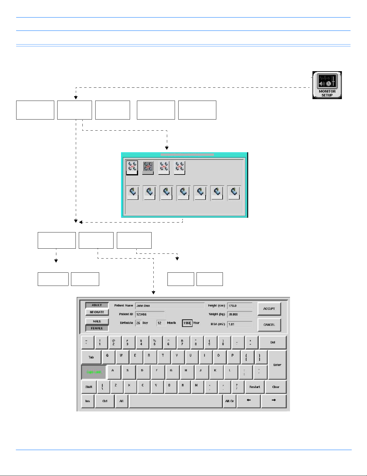
Admit/Discharge
NICU
BED01
BED01 BED02 BED0 3 BED04 BED05
BED06
BED07
ICU
CCUMICU
MONITOR SETUP-Admit/Discharge: Select Bed
For bedside
monitoring
Directory of Keys — UCW and Ultraview 1700
To enter patient name, ID, or other data
MONITOR SETUP
TONES
ADMIT/
DISCHARGE
MONITOR
CONFIG.
RECORDER
CONFIG.
PRIVILEGED
ACCESS
For central
monitoring
ADMIT/DISCHARGE - Select function
ADMIT
CHANGE
DATA
DISCHARGE
Admit - Purge existing data for this bed? DISCHARGE - Are you sure? (All data for the bed will be purged)
YES NO YES NO
Note:
Based on features purchased, more or fewer keys may appear here than on your menu screens.
Ultraview Care Network Operations Manual 3-2
Page 45

Admit/Discharge
Contents
Overview. . . . . . . . . . . . . . . . . . . . . . . . . . . . . . . . . . . . . . . . . . . . . . . . . . . . . . . . . . . . . . . . . . . . . . . . . . . . . 3
Entering New Patient Information . . . . . . . . . . . . . . . . . . . . . . . . . . . . . . . . . . . . . . . . . . . . . . . . . . . . . . . . . . 3
Changing Patient Information . . . . . . . . . . . . . . . . . . . . . . . . . . . . . . . . . . . . . . . . . . . . . . . . . . . . . . . . . . . . . 9
Discharging a Patient . . . . . . . . . . . . . . . . . . . . . . . . . . . . . . . . . . . . . . . . . . . . . . . . . . . . . . . . . . . . . . . . . . 10
Admit/Discharge Troubleshooting Guide . . . . . . . . . . . . . . . . . . . . . . . . . . . . . . . . . . . . . . . . . . . . . . . . . . . 11
Overview
This chapter describes how to enter new patient data, change data for an existing patient, and delete patient
data from a Ultraview Care Network monitor.
You can access the Admit/Discharge menu on either the central or bedside monitor. However, if you are
accessing this menu at a central monitor, you must also select the patient's bed (this is not necessary at a
bedside monitor).
Entering New Patient Information
The only information required when admitting a patient to the system is the patient's name (up to 40
characters). Entering the patient's ID number (up to 15 characters) is optional.
This section discusses how to enter the following patient information, depending on which monitor you have.
• Patient Name and ID
(refer to Ultraview 1030/1050/1500/1600 on page 3-5 and UCW/Ultraview 1700 on page 3-6)
• Height, Weight, and BSA (body surface area)
(refer to Entering Height, Weight, and BSA on page 3-7)
• Date of Birth
(refer to Entering Patient Date of Birth on page 3-9)
• Patient Type and Gender
(refer to Entering Patient Type and Gender on page 3-9)
Ultraview Care Network Operations Manual 3-3
Page 46

Admit/Discharge
To enter new patient information (Ultraview 1030/1050/1500/1600):
• Touch MONITOR SETUP.
• Touch ADMIT/DISCHARGE.
• Touch ADMIT.
• Select YES to purge the existing data.
• Select ID and/or NAME.
• Enter information using the on-screen keyboard.
• Touch ENTER.
• Touch PREVIOUS MENU (if necessary).
• Select DATE OF BIRTH and enter MONTH, DAY, and YEAR.
• Touch ENTER.
• Touch PREVIOUS MENU.
• Select HEIGHT, WEIGHT, or BSA and enter information using the on-screen keypad.
• Touch ENTER.
• Touch MALE/FEMALE until the correct gender is highlighted.
• Touch ADULT/NEONATE until the relevant selection is highlighted.
To enter new patient information (UCW/Ultraview 1700):
• Touch MONITOR SETUP.
• Touch ADMIT/DISCHARGE.
• Select a subnet or a bed (central only).
• If you selected a subnet, then select a bed.
• Touch ADMIT.
• Select YES to purge the existing data.
• Select a field on the on-screen keyboard.
• Enter information using the on-screen keyboard.
• Touch ENTER after completing each field.
• Select ADULT or NEONATE.
• Select MALE or FEMALE.
• Touch ACCEPT to store the new patient data.
Using the On-Screen Keyboard
A keyboard is displayed on the monitor screen as you begin the process of admitting or changing data on a
patient. The on-screen keyboard functions differently depending on the monitor model you have. You can also
use the external computer keyboard to enter patient data into the selected field.
Ultraview Care Network Operations Manual 3-4
Page 47

Admit/Discharge
RESTART CLEAR BACKSPACE
!
1
@
2
#
3
$
4
%
5
^
6
&
7
*
8
(
9
)
0
_
-
QWERTYUIOP
“
‘
CAPS
LOCK
ASDFGHJKL
:
;
SHIFTZXC VB NM
<
,
>
.
?
/
ENTER
Ultraview 1030/1050/1500/1600
The keyboard shown in Figure 3-1 appears when you touch the NAME or ID key under the ADMIT and
CHANGE DATA keys. Use this keyboard to enter or change the patient’s name or ID only.
Figure 3-1: Ultraview 1030/1050/1500/1600 on-screen keyboard
Ultraview Care Network Operations Manual 3-5
Page 48
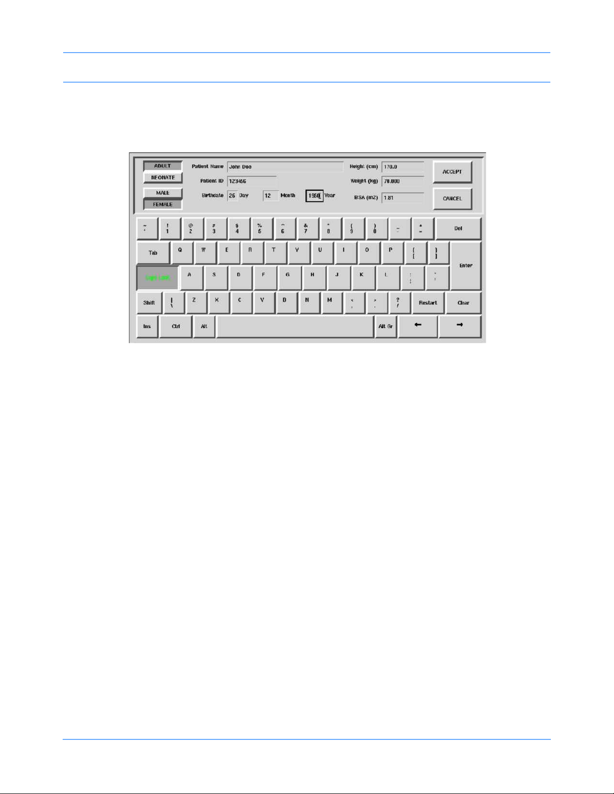
Admit/Discharge
UCW/Ultraview 1700
The keyboard shown in Figure 3-2 appears when you touch the ADMIT or CHANGE DATA keys. You can use
this keyboard to enter or change ALL patient information.
Figure 3-2: UCW/Ultraview 1700 on-screen keyboard
Character Keys — Each character key you touch displays above the keyboard on the 1030, 1050, 1500 and
1600. It displays in the selected field on the UCW and Ultraview 1700.
Function Keys —
DEL or BACKSPACE deletes the character to the LEFT of the cursor.
moves the cursor left one position.
moves the cursor right one position.
RESTART redisplays the last name or value stored and deletes all earlier changes.
CLEAR deletes the currently displayed name or value.
ENTER stores the data displayed in the selected field into system memory.
TAB moves the cursor to the next field.
CAPS LOCK locks the keyboard in all caps mode.
SHIFT toggles the shift mode on and off.
INS inserts the selected data in the current space.
SPACE BAR inserts a space.
ACCEPT enters the data into the system and completes the admit.
Ultraview Care Network Operations Manual 3-6
Page 49

Admit/Discharge
Entering Height, Weight, and BSA
Table 1 lists the default values and valid ranges for height, weight, and BSA (body surface area). You can
adjust the values up or down within the valid range. The values last set for height, weight, and BSA remain until
manually changed.
Table 1: Height, Weight, BSA Default Value
Default Value
(1030, 1050, 1500, 1600 only)
Label Name Units
BSA
HT Height
WT Weight
The parameter value can be displayed in either U.S or metric units (see your system administrator for details).
The system automatically computes BSA from the values entered for height and weight and uses this BSA
value to obtain indexed values for physiologic calculations such as Cardiac Output.
Toggle the ADULT/NEONATE key to display the respective adult and neonatal default values for height,
weight, and BSA.
Note:
On central monitors, the ADULT/NEONATE key appears dotted if the remote monitor where the admit/
discharge occurs does not support the patient type selection.
Body Surface
Area
m
cm
in
kg
lb
2
1.81 0.11 0.03 to 3.69
170
66.9
70.000
154.324
35
13.8
1.500
3.307
Valid Range Adult Neonatal
20 to 215
7.9 to 84.6
0.2 to 250.0
0.441 to 551.156
Ultraview Care Network Operations Manual 3-7
Page 50

Admit/Discharge
HT 66.9
789
REMOVE
KEYPAD
CLEAR
456RESTORE
123
ENTER
+/- 0 .
Using the On-Screen Keypad (Ultraview 1030/1050/1500/1600 only)
When you select either the HEIGHT, WEIGHT, or BSA parameter key, an on-screen keypad will appear
displaying the selected parameter in the upper left corner (Figure 3-3). The current parameter value is
displayed in the upper right corner. You can change this parameter value up or down using the arrow keys, or
you can use the keypad numbers to enter up to seven digits, including a decimal point. The system recognizes
any value within the range that displays immediately below the keypad. The default values for height, weight,
and BSA are displayed if other values are not available.
Figure 3-3: Ultraview 1030/1050/1500/1600 on-screen keypad
Numeric Keys — The 0 to 9 and decimal point keys allow you to enter numeric data.
Function Keys —
increases or decreases the displayed parameter value by 1.0, 0.1, 0.01, or 0.001 depending on the
resolution of the input value.
ENTER stores the value displayed in the top right corner of the keypad in system memory. The ENTER
key must be touched to store the value.
CLEAR sets the value in the top right corner of the keypad to 0.
RESTORE returns the previous value or displays the stored value.
REMOVE KEYPAD clears the keypad from the screen and restores the previously displayed value.
+/- This key is disabled.
Ultraview Care Network Operations Manual 3-8
Page 51

Admit/Discharge
Entering Patient Date of Birth
Ultraview 1030/1050/1500/1600
To enter the patient’s date of birth, touch the DATE OF BIRTH key and enter the month, day, and year. Touch
ENTER to store the information in the monitor’s memory.
UCW/Ultraview 1700
To enter the patient’s date of birth, use the TAB key to move to the Birthdate field on the on-screen keyboard
and enter the Day, Month, and Year. Touch ENTER and ACCEPT to store the information in the monitor’s
memory.
Entering Patient Type and Gender
To select the patient type, touch the ADULT/NEONATE key. Once the selection has been made, it is stored in
the monitor’s memory and either ADULT or NEONATE is highlighted. If you use one patient type exclusively,
your system administrator may set the selection to that specific type.
To select the patient gender, touch the MALE/FEMALE key. Once the selection has been made, it is stored in
the monitor’s memory and either MALE or FEMALE is highlighted.
Changing Patient Information
To alter any existing patient information, use the CHANGE DATA key. This key does not function when there is
no patient name or ID number stored in the system.
To change patient information:
• Touch MONITOR SETUP.
• Touch ADMIT/DISCHARGE.
• Select a subnet or a bed (central only).
• If you selected a subnet, then select a bed.
• Touch CHANGE DATA.
• Make desired changes as described under Entering New Patient Information on
page 3-3.
Ultraview Care Network Operations Manual 3-9
Page 52

Admit/Discharge
Discharging a Patient
To clear the bedside monitor of existing patient information, touch the DISCHARGE key. You can now purge
the existing patient data.
To discharge a patient:
• Touch MONITOR SETUP.
• Touch ADMIT/DISCHARGE.
• Select a subnet or a bed (central only).
• If you selected a subnet, then select a bed.
• Touch DISCHARGE.
• Select YES to purge the existing data.
Ultraview Care Network Operations Manual 3-10
Page 53

Admit/Discharge
Admit/Discharge Troubleshooting Guide
Clinical Situation Possible Cause Solution
Patient name incorrect as
entered on keyboard
menu
■ Name exceeds 40 character
maximum and system has written
over some characters.
■ No patient name or ID number
stored in system.
■ Re-enter name using
40 characters or less.
■ Enter name or ID number.
Ultraview Care Network Operations Manual 3-11
Page 54

Page 55

Printing
RECORDER
CONFIG.
RECORDING
DURATION
ALARM
PAR AMS
RECORD
ALL
RECORD
PRESELECTED A
RECORD
PRESELECTED B
CONTINUOUS
RECORD
PRINTER
(1 - 8)
STOP
RECORDING
CONVERT TO
CONTINUOUS
To set up the printer:
To obtain recordings from the monitor:
Touch RECORD once
Touch this key, then touch
RECORDER MENU
Touch RECORD twice
the desired parameter key
(up to four), for each parameter
to be continuously recorded
PRINTER (1 - 8 ) CONTROL MENU
1 42
Number of Recorder Channels
RECORDING
DESTINATION
NETWORK BOTH
ALARM RECORDINGS TO:
THIS
MONITOR
OTHER RECORDINGS TO:
VITALS
SETUP
RECORD
PRINT
VITAL SIGNS
SYSTEM PRINTER MODULE
To control recordings from the monitor using the system printer module:
12 SEC
PRIVILEGED
ACCESS
See following pages
MONITOR SETUP
RECORDER CONFIGURATION
Select duration
of recordings
initiated from
this monitor
Select parameters
that require
alarm recording
from bed x
20 SEC
ECG
ONOFF
...
ONOFF
NETWORK
THIS
MONITOR
SLOW
ON OFF
PRINTER
ON OFF
Directory of Keys — Monitor Setup Level
Note:
Based on features purchased, more or fewer keys may appear here than on your menu screens.
Ultraview Care Network Operations Manual 4-1
Page 56

Printing
SELECT
BIOMED LEVEL: Select Parameter
ACCESS
Enter BIOMED password
RECORDER
NAMES
RECORDER
SETUP
RECORDERS
ALARM EXTENDED
DURATION SETTING
RECORDER SETUP - Select Parameter
Select recorder name to change
Selecting a key displays keyboard for renaming printer.
RECORDER A
RECORDER B
Select priority of recorder to be assigned to bed x
Select RECORDER x recorder for bed x
Laz1
PRIVILEGED
ALARM EXTENDED DURATION SETTING
SELECTION
AUTO BACKUP
0 SECONDS 6 SECONDS 12 SECONDS
Laz1
Directory of Keys — Biomed Level
Note:
Based on features purchased, more or fewer keys may appear here than on your menu screens.
Ultraview Care Network Operations Manual 4-2
Page 57

Printing
PRIVILEGED
ACCESS
Enter CLINICAL password
PRESELECTED RECORDINGS - Select configuration to change
Select option to change - X: (current selection displays)
SELECT
TYPE
SELECT
BED
Select recording type - X: Beds = (current selection displays)
ALL BEDSIDE
BEDSIDE PARAM(S)
CONFIGURED
PARAMETERS
Select beds/subnets - X: (current selection displays)
ALL
SUBNETS
THIS
SUBNET
THIS
MONITOR
ALL BEDS ON
THIS MONITOR
PRESELECTED A PRESELECTED B
PRESELECTED
RECORDINGS
Directory of Keys — Clinical Level
Refer to To obtain recordings from the monitor and To control recordings from the monitor using the system printer module on page 4-1 for
more UCW and Ultraview 1700 keys.
Note:
Based on features purchased, more or fewer keys may appear here than on your menu screens.
Ultraview Care Network Operations Manual 4-3
Page 58

Page 59

Printing
Contents
Overview. . . . . . . . . . . . . . . . . . . . . . . . . . . . . . . . . . . . . . . . . . . . . . . . . . . . . . . . . . . . . . . . . . . . . . . . . . . . . 5
Bedside Printer Module . . . . . . . . . . . . . . . . . . . . . . . . . . . . . . . . . . . . . . . . . . . . . . . . . . . . . . . . . . . . . . . . . 6
System Printer Module . . . . . . . . . . . . . . . . . . . . . . . . . . . . . . . . . . . . . . . . . . . . . . . . . . . . . . . . . . . . . . . . . . 7
Ultraview 1030/1050 Monitor Printers. . . . . . . . . . . . . . . . . . . . . . . . . . . . . . . . . . . . . . . . . . . . . . . . . . . . . . . 7
PrintMaster . . . . . . . . . . . . . . . . . . . . . . . . . . . . . . . . . . . . . . . . . . . . . . . . . . . . . . . . . . . . . . . . . . . . . . . . . . . 8
Printing Priorities. . . . . . . . . . . . . . . . . . . . . . . . . . . . . . . . . . . . . . . . . . . . . . . . . . . . . . . . . . . . . . . . . . . . . . 12
Selecting Print Duration . . . . . . . . . . . . . . . . . . . . . . . . . . . . . . . . . . . . . . . . . . . . . . . . . . . . . . . . . . . . . . . . 14
Printer Key Functions . . . . . . . . . . . . . . . . . . . . . . . . . . . . . . . . . . . . . . . . . . . . . . . . . . . . . . . . . . . . . . . . . . 15
Recording Alarms . . . . . . . . . . . . . . . . . . . . . . . . . . . . . . . . . . . . . . . . . . . . . . . . . . . . . . . . . . . . . . . . . . . . . 16
Selecting Recording Destination. . . . . . . . . . . . . . . . . . . . . . . . . . . . . . . . . . . . . . . . . . . . . . . . . . . . . . . . . . 16
Printing via Monitors . . . . . . . . . . . . . . . . . . . . . . . . . . . . . . . . . . . . . . . . . . . . . . . . . . . . . . . . . . . . . . . . . . . 17
Defining Preselected Recording Keys . . . . . . . . . . . . . . . . . . . . . . . . . . . . . . . . . . . . . . . . . . . . . . . . . . . . . 19
Loading Paper . . . . . . . . . . . . . . . . . . . . . . . . . . . . . . . . . . . . . . . . . . . . . . . . . . . . . . . . . . . . . . . . . . . . . . . 20
Paper Out Conditions . . . . . . . . . . . . . . . . . . . . . . . . . . . . . . . . . . . . . . . . . . . . . . . . . . . . . . . . . . . . . . . . . . 23
Record Vitals Report (Ultraview 1030/1050 Only) . . . . . . . . . . . . . . . . . . . . . . . . . . . . . . . . . . . . . . . . . . . . 23
Printing Troubleshooting Guide . . . . . . . . . . . . . . . . . . . . . . . . . . . . . . . . . . . . . . . . . . . . . . . . . . . . . . . . . . 26
Overview
This chapter documents the printing functions of the following printing components:
• 90449 bedside printer module
• 90469 (two- and four-channel) system printer module
• Record Vitals Report
• Ultraview 1030/1050 printer
• 90838 PrintMaster
The chapter reviews each printer and includes information and instructions about its features.
Printers can provide strip chart recordings of the following:
• Automatic recordings of any parameter in an alarm condition (if configured in the MCM and if the Record
Alarms Parameters function is enabled for that parameter).
• Parameter data such as:
- Patient name, bed name, time and date of recording
- Vital signs, edgeprint annotation, and scaling information
- Waveform data (including timing tick marks and a grid)
- Arrhythmia/ST segments
™
laser printer
• Non-waveform data displayed on the screen such as graphic trends, data tables, hemodynamic
calculations, and cardiac output.
Ultraview Care Network Operations Manual 4-5
Page 60

Printing
Bedside Printer Module
The 90449 bedside printer module is a two-channel printer that provides automatic and manual recordings of
parameter data on 50 mm fanfold paper.
Figure 4-1: 90449 bedside printer module
The bedside printer module prints recordings of parameters in alarm conditions, requested waveforms, and
non-waveform data such as:
• tabular trends
• hemodynamic calculations
• drug dose calculations
• graphic trends waveform data
Note:
The bedside printer is not designed for use as a system printer and will not function correctly if used in this
manner.
Ultraview Care Network Operations Manual 4-6
Page 61

Printing
System Printer Module
The 90469 system printer module is a two- or four-channel printer that provides automatic and manual
recordings of parameter data on 50 mm or 120 mm fanfold paper.
Figure 4-2: 90469 system printer module
The Ultraview Care Network system printer module prints recordings of parameters in alarm conditions,
requested waveforms, and non-waveform data such as:
• tabular trends
• hemodynamic calculations
• drug dose calculations
• graphic trends waveform data
Ultraview 1030/1050 Monitor Printers
The printers in the Ultraview 1030/1050 monitors are two-channel printers that provide automatic and manual
recordings of parameter data on 50 mm roll paper. The printers print recordings of parameters in alarm
conditions, requested waveforms, and non-waveform data.
Ultraview Care Network Operations Manual 4-7
Page 62

Printing
PrintMaster
The 90838 PrintMaster is a four-channel, network printer that provides automatic and manual recordings of
parameter data on 8 1/2 × 11 or A4 paper.
Figure 4-3: PrintMaster
Display panel
Top cover release
Top printout tray
Rear cover release
Central processing unit
Paper drawer
Front cover release
The PrintMaster printer functions the same as the bedside and system printer modules in that it prints
recordings of parameters in alarm conditions, requested waveforms, and non-waveform data.
Ultraview Care Network Operations Manual 4-8
Page 63

Printing
Clearing Paper Jams (PrintMaster)
If a paper jam occurs, a message will indicate the location of the jam. Once the jam is cleared, the cover
closed, and the printer warmed up, the printer will print all the pages affected by the jam.
One of three paper jam messages may appear on the printer display:
Table 1: PrintMaster Paper Jam Messages
Message Text Solution
1 Pull out the paper drawer.
2 Remove the sheet that did not feed.
PAPER INPUT JAM
PAPER FEED JAM
PAPER EXIT JAM
3 Inspect remaining sheets to ensure they are not wrinkled or
stuck together.
4 Close the paper drawer.
5 Open and close the top cover to clear the paper jam message.
1 Open the top cover.
CAUTION! THE FUSING UNIT IS HOT.
2 Lift out the image drum cartridge.
3 Carefully remove the jammed paper.
4 Replace the image drum cartridge.
5 Close the top cover.
1 Open the top cover and the rear cover to release the roller
pressure.
CAUTION! THE FUSING UNIT IS HOT.
2 Pull the paper out from the rear or inside of the printer.
3 Close the top and rear covers.
Terminating a Print Job (PrintMaster)
To terminate an undesired multi-page print job that is currently printing, power the printer OFF (until the front
panel lights go out) then turn it back ON. This cancels any print job in process.
Replacing the Toner Cartridge (PrintMaster)
When the TONER LOW message appears on the printer display:
1 Open the top cover.
2 Lift and pull the toner cartridge out at an angle.
3 Insert the new cartridge.
4 Close the top cover.
Ultraview Care Network Operations Manual 4-9
Page 64

Printing
PrintMaster Display Messages
Table 2: Printer Display Messages
Message Text Reason
ON-LINE Ready to receive data.
OFF-LINE Not ready to receive data.
DATA PRESENT Print data is in buffer.
PRINTING Data is being received and printed.
POWER SAVING Power saving mode is active.
LOW TONER
TONER EMPTY REPLACE TNR
CART
TONER SENSOR Malfunction of toner sensor is detected.
RESET
PRINT FONTS Font page is printing.
DRUM CLEANING Drum cleaning page is printing.
PRINT DEMO PAGE Demo page is printing.
PRINT MENU Menu page is printing.
CHANGE DRUM
FUSER LIFE Fuser near end of life. Contact a field service engineer.
COPY nnn/mmm
Toner is running out. 100 more pages can be printed
when this message is first displayed.
Toner cartridge is empty. Printer will stop receiving
printing until toner cartridge is replaced.
Manual reset was initiated. All temporary fonts and
macros are deleted.
Drum near 90% of life. Change drum and reset drum
counter.
Indicates number of copies printed.
nnn = page being printed.
mmm = total copies requested.
STACKER FULL
REMOVE THE PAPER
mmmmm MANUAL PAPER
REQUEST
Ultraview Care Network Operations Manual 4-10
Paper exit bin is full. Printing is stopped until paper is
removed.
Insert requested paper. Printing is stopped until paper is
provided or RECOVER is pressed.
mmmmm = requested size.
Page 65

Printing
Table 2: Printer Display Messages (continued)
Message Text Reason
mmmmm ttttttt PAPER REQUEST
PAPER OUT ttttttt
ERROR MEMORY OVERFLOW
ERROR RECEIVE BUFFER
OVERFLOW
ERROR PRINT OVERRUN
ERROR HOST I/F
CARD NOT FOUND PLEASE
REINSERT
ERROR PAPER SIZE CHECK ttttttt
Paper size mmmmm requested at tray ttttttt. Printing is
stopped until paper is provided or RECOVER is pressed.
Paper is out at tray ttttttt. Printing is stopped until paper is
provided.
Page data exceeds available memory. Press RECOVER
to continue. Adjust RASTER BUFFER, RECEIVE
BUFFER, and/or FONT PROTECT in menu, and resend
job.
Received buffer overflow. Data was lost. Press
RECOVER to continue, and resend job.
Data too complex for current RASTER BUFFER setting.
Increase RASTER BUFFER value and resend job or add
memory. Press RECOVER to continue.
Host interface error. Data was lost. Press RECOVER to
continue, and resend job.
Font card removed. Reinstall card. Press RECOVER to
continue, and resend job.
Incorrect paper size detected for tray ttttttt. Provide
correct paper size and press RECOVER to continue.
PAPER INPUT JAM CHECK ttttttt
PAPER FEED JAM CHECK tttttttt
PAPER EXIT JAM REMOVE THE
PAPER
COVER OPEN Close cover.
EEPROM RESETTING
ERROR CARD FORMAT CHECK
ERROR CARD REMOVED ON-LINE
Ultraview Care Network Operations Manual 4-11
Paper jammed while being supplied from tray ttttttt. Clear
jam and open/close top cover.
Paper jammed during feeding from tray tttttttt. Clear jam
and open/close top cover.
Paper jammed during exit. Clear jam and open/close top
cover.
EEPROM resetting to factory defaults; returns to ONLINE.
Installed font card has invalid data. Turn off printer to
clear error.
Font card removed while ON-LINE. Turn off printer to
clear error.
Page 66

Printing
Table 2: Printer Display Messages (continued)
Message Text Reason
ERROR CONTROLLER nn
On -aaaaaaaa
88888888
88888888
INITIALIZING Controller is being initialized at power ON.
RESET TO SAVE
The PrintMaster will beep every 15 seconds under the following conditions:
• paper jam
• missing toner cartridge
• top cover or back door open
• power to printer is OFF
• power cord is disconnected
• printer cable is disconnected
• printer in Not Ready mode
Controller error, nn = error type. Power off printer to clear
error. If error continues, contact your field service
engineer.
Displayed when power is turned ON. This is done to test
all LEDs and LCD segments.
Press RESET to save menu changes. Menu changes
cannot be reset automatically because data is present in
buffer.
Printing Priorities
Each Spacelabs Healthcare network-connected patient monitor is capable of sending recordings to two
network printers. With two printers available to monitors on the network, printer selection rules are used to
strike the best possible balance to:
• generate the most timely output of high-priority recordings;
• ensure that subsequent recordings from one patient over a short time span are processed by one printer;
and
• use paper as efficiently as possible.
When the printing load is heavy, these objectives may conflict. The factors that are taken into consideration
when a print request occurs include:
• Are either of the two printers outputting, holding in memory queue, or loading in queue a print job from this
monitor?
• Are either of the printers idle?
• Is the record request a high-priority request (alarm vs. manual)?
• Are either of the printers currently printing a continuous recording?
Ultraview Care Network Operations Manual 4-12
Page 67

Printing
• Are either of the printers’ queues full?
• Which of the printers is the preferred size for this request (1, 2, or 4 channels)?
At the time of a printing request, the monitor from which the request is coming evaluates both of the available
printers one at a time, leading to a score for each of the two printers. Each printer’s evaluation passes all the
way through the priority tree from the top score to the score at the bottom of the tree. The printer generating the
highest score gets the job. If the evaluation produces the same score for each printer, the print job is sent to
the printer designated as the primary printer for that monitor.
The printing rules mentioned work best when the two printers are sharing the printing load. The monitor
automatically determines which printer is best for each type of recording. Another configuration designates one
printer as the primary printer and the other as the backup printer. All recordings are sent to the primary printer
unless it is unable to print for the following reasons:
• Offline
• Out of paper
• Disconnected from network
• Powered OFF
• All print queues full
• Unable to accept recording type
If the primary printer is unable to print, the recordings are then sent to the backup printer unless it is also
unable to print for the reasons listed above.
Some networks are configured so that recordings from a given monitor are directed to only one of the printers
on the network. In this case only one printer will be available instead of two during possible times of
simultaneous multiple bed alarms. The selection rules will not be applicable, and print performance will be
affected.
The following list defines recording priorities in descending order:
Highest
• Alarm recording or a manual recording request via a monitor
• RECORD ALL request via a bedside monitor
• RECORD ALL request via a central monitor
• Non-waveform recordings
Lowest
• All Arrhythmia/ST classes
In all network printing cases:
• High-priority print jobs bump lower-priority jobs. For instance, an alarm recording will bump graphic
trends to a lower position in the print queue.
• A fully loaded printer will bump graphic trends out of the queue.
• A high-priority request erases as many lower-priority requests as needed to make room for the data it
contains.
Note:
A status message is not displayed when a print request replacement occurs.
Ultraview Care Network Operations Manual 4-13
Page 68

Printing
Selecting Print Duration
Waveform Data
In the absence of an alarm condition, the print request origin determines the length of time that waveform data
(ECG, ART, RESP, etc.) is recorded.
Recordings requested via the monitor are either 12 or 20 seconds in duration. This is selectable via the
RECORDING DURATION key. Recordings start with a few seconds of data received just prior to the print
request, followed by real-time data.
Note:
The RECORDING DURATION key will not display if the recording duration has been preset by your
system administrator.
To select print duration from the monitor:
• Touch MONITOR SETUP.
• Touch RECORDER CONFIG.
• Touch RECORDING DURATION to change length of time for printing.
Non-Waveform Data
The length of time the printer requires to record non-waveform data, such as graphs and data tables, depends
on the complexity of the data and cannot be pre-determined.
Ultraview Care Network Operations Manual 4-14
Page 69

Printing
Printer Key Functions
Ultraview 1030/1050 Monitor, Bedside, and System Printer Modules
Printer control keys for the bedside and system printer modules are located on the module front. The printers
can also be controlled by keys on the monitor itself.
Table 3: Key Descriptions
Key Function
Changes the print speed of waveform recordings to 6.25 mm/second.
SLOW
ON/OFF
CONTINUE
Pressing SLOW a second time returns the printer to the current system
sweep speed. SLOW has no effect on the print speed of non-waveform
recordings (data tables, graphics, etc.).
• When the printer is offline, press this key to feed roll paper at
25 mm/second or to feed one sheet of perforated paper through
printer module.
• When the printer is online and currently printing a 12- or 20-second
waveform recording, press CONTINUE to convert to a continuous
recording. If you press CONTINUE, the 12- or 20-second
recording completes, followed by a horizontal line, and then the
current data. The horizontal line appears even on recordings that
are not in a queue, but are the only request.
STOP
RECORDING
PRINTER
ON/OFF
To access printer control keys from the monitor:
• Touch NORMAL SCREEN.
• Touch RECORD.
• Select the desired key.
• Stops any printing currently in progress and moves to the next print
request in the queue.
• Stops any roll paper advance currently in progress.
Takes the printer offline without turning the power OFF. Alarms and print
requests are now ignored. An LED (located either in the key or on the
front panel of system printer) illuminates when this function is selected.
Ultraview Care Network Operations Manual 4-15
Page 70

Printing
Recording Alarms
An alarm recording may be triggered whenever a parameter enters an alarm condition. Recordings in the
process of printing cannot be interrupted or delayed by a new alarm condition.
Note:
Parameter alarm recordings can be set to OFF so that a printer will not respond to an alarm condition (the
alarm tone and accompanying alarm message are unaffected). Refer to Automatic Recording of an Alarm
on page 2-11 for more details.
To select parameters for alarm recording and generate automatic recordings on a
bedside recorder:
• Touch MONITOR SETUP.
• Touch RECORDER CONFIG.
• Select RECORDING DESTINATION.
• Select a destination for the alarm recording.
• Touch PREVIOUS MENU.
• Touch ALARM PARAMS.
• Select parameter key(s) ON to initiate a recording in case of alarm. If the parameter
key is OFF, no alarm recording is produced for that parameter in an alarm condition.
Selecting Recording Destination
The Recording Destination menu contains keys that direct alarm recordings to a bedside recorder, a network
printer, or both. All other recordings may be directed only to a bedside printer or a network printer, but not both.
Alarm recordings begin with several seconds of pre-alarm waveform data and continue for as long as the alarm
condition exists (a minimum of 12 seconds).
Note:
12-lead ECG reports will always print to the 90838 printer, if available, regardless of the destination
settings for the recording.
Ultraview Care Network Operations Manual 4-16
Page 71

Printing
Printing via Monitors
Non-Waveform Data
Whenever you display non-waveform data on either the central or bedside monitors, a PRINT key displays.
The RECORD key is not functional for printing non-waveform data. As a result, non-waveform data must be
displayed before it can be recorded.
Non-waveform data usually occupies a minimum of two slots in the printer's queue due to the volume of
information being sent. This means that a single non-waveform recording may take up as much room on the
strip chart as two simultaneous waveform recordings.
If the data cannot fit on the strip at one time, it is separated horizontally, printing first the top half and then the
bottom half of the data.
To start a manual recording via the monitor:
• Touch RECORD.
• Touch up to four flashing parameter keys.
• Touch CANCEL RECORD SELECTION(S) to terminate.
-OR-
• Touch STOP RECORDING in the PRINTER CONTROLS menu to terminate.
Waveform Data
Waveform data is recorded using the RECORD key on the monitor.
Note:
• Requests for recording waveform data are limited to only those waveform parameters that are currently
displayed on the screen (except ECG where all leads print).
• If a parameter menu is left on the screen, the CONTINUOUS RECORD key is not displayed.
Each time you touch RECORD on the monitor, the CONTINUOUS RECORD key displays and waveform
parameter keys flash for up to four seconds. You must make your key selection within this four-second
window. This window stays open for an additional two to four seconds each time a key is selected. Once the
parameter keys stop flashing, any waveforms that have been selected are automatically sent to the printer for
recording.
Touch the RECORD key twice to display the Recording menu. From the Recording menu you can:
• Record all parameters currently on this screen by touching RECORD ALL.
• Initiate a preselected group of recordings by touching PRESELECTED A or PRESELECTED B.
• Select PRINT VITAL SIGNS to manually print the vital signs you have selected (refer to Record Vitals
Report (Ultraview 1030/1050 Only) on page 4-23 for more information).
RECORD ALL and PRESELECTED A OR B recordings are eight seconds in duration.
Ultraview Care Network Operations Manual 4-17
Page 72

Printing
To print group recordings via the monitor:
• Touch RECORD twice.
• Touch RECORD ALL.
-OR-
• Touch RECORD PRESELECTED A or B.
To start a continuous recording via the monitor:
• Touch RECORD.
• Touch CONTINUOUS RECORD, then touch the desired parameter key (up to four, for
each parameter to be continuously recorded.
• Touch CANCEL RECORD SELECTION to restart the selection process.
To stop a continuous recording via the monitor:
• Touch RECORD.
• Touch STOP CONT. RECORD.
-OR-
• Touch STOP RECORDING in PRINTER CONTROLS.
Group Recordings
The printers record all the requested parameters on one patient before beginning on the parameters of the
next patient. Under no circumstances will the printer combine the parameters of different patients onto the
same strip chart. Recordings in the process of being printed cannot be interrupted or delayed by additional
print requests.
Ultraview Care Network Operations Manual 4-18
Page 73

Printing
Defining Preselected Recording Keys
The Preselected Recordings function enables you to define which beds and parameters will be automatically
recorded. The preselected group is established by the system administrator. For UCW and Ultraview 1700
monitors this is set up through the Clinical level of the Privileged Access menu.
To define the PRESELECTED A and B parameters (UCW and Ultraview 1700):
• Touch MONITOR SETUP.
• Touch PRIVILEGED ACCESS.
• Enter Clinical password.
• Touch PRESELECTED RECORDINGS.
• Touch key to be defined (A or B).
• Touch SELECT TYPE.
• Touch FIRST 2 BEDSIDE PARAM(S) and use arrow keys to cycle through parameter
selections: ALL BEDSIDE PARAM(S) or FIRST n BEDSIDE PARAM(S) (where n is 1,
2, 4 or 8).
-OR-
• Touch CONFIGURED PARAMETERS and toggle desired parameters ON or OFF.
• Touch PREVIOUS menu twice to define the remaining PRESELECTED key.
To define the PRESELECTED A and B beds (UCW and Ultraview 1700):
• Touch MONITOR SETUP.
• Touch PRIVILEGED ACCESS.
• Enter Clinical password.
• Touch PRESELECTED RECORDINGS.
• Touch key to be defined (A or B).
• Touch SELECT BEDS.
• Select ALL SUBNETS.
-OR-
• Select THIS SUBNET.
-OR-
• Select THIS MONITOR.
• Touch PREVIOUS menu twice to define the remaining PRESELECTED key.
Ultraview Care Network Operations Manual 4-19
Page 74

Printing
Note orientation of small cue mark
Loading Paper
Bedside Printer Module
The small black rectangular cue mark on the bedside printer paper must face out and be at the bottom of the
tray when loading paper into the tray.
Figure 4-4: Bedside printer module paper tray
Each recording starts at the Z-fold perforation and blank sheets are not placed between successive print
requests.
To load paper in a bedside printer module (2-channel only):
• Press eject button next to PAPER OUT light.
• Withdraw plastic paper tray.
• Discard old cardboard retainer inside tray.
• Remove label from new paper but keep cardboard retainer in place around one end.
• Start inserting paper into tray, beginning with cardboard retainer end.
• With paper halfway into tray, lift up spring-loaded roller.
• Bring out top fold of paper from under top end of cardboard retainer.
• Bring top fold over top of spring-loaded roller.
• Release spring-loaded roller onto remainder of paper.
• Insert stack fully.
• Unfold paper and position over top of black roller at end of tray.
• Slide tray completely back into printer module.
Ultraview Care Network Operations Manual 4-20
Page 75

Printing
four-channel two-channel
paper roller
paper roller
cue mark
cue mark
System Printer Module
The system printer module has a slide-out plastic tray that accepts packets of Z-fold paper. The two-channel
printer uses 50 mm wide by 27 m long paper. The four-channel printer uses 120 mm wide by 45.7 m long
paper. Each sheet has a small black rectangular cue mark located along the edge used to load the paper into
the tray.
Figure 4-5: System printer module paper trays (top view)
To load paper in a system printer module (2- or 4-channel):
• Press eject button next to PAPER OUT light.
• Withdraw plastic paper tray.
• Discard old cardboard retainer inside tray (2-channel only).
• Remove label from new paper but keep cardboard retainer in place around one end
(2-channel only).
• Discard 4-channel container.
• Start inserting paper into tray, beginning with cardboard retainer end (2-channel only).
• Make sure black squares are in the top left corner of the pages (4-channel).
• Insert stack fully.
• Unfold paper and position over top of black roller at end of tray.
• Slide tray completely back into printer module.
Ultraview Care Network Operations Manual 4-21
Page 76

Printing
Ultraview 1030/1050 Printers
The Ultraview 1030/1050 monitor’s printer uses 50 mm wide by 30 m long rolls of thermal paper. The printer
has an automatic self-feed mechanism for threading the paper through the rollers.
Figure 4-6: Loading printer paper
To load paper in the Ultraview 1030/1050 printer:
• Press release button on door.
• Open paper tray door all the way.
• Snap new roll into place.
• Pull out 6 to 12 inches of paper.
• Close door.
PrintMaster
The PrintMaster printer has a slide-out paper drawer that accepts up to 500 pages of letter or A4-sized copy
paper. Slide the drawer out of the printer, place the paper (according to orientation) into the cassette, and
place the cassette back into the printer.
Ultraview Care Network Operations Manual 4-22
Page 77

Printing
START
TIME
PRINT
VITAL SIGNS
Configure parameters or start vitals recording
SELECT
VITALS
SETUP
DATA
INTERVAL PARAMETERS
Paper Out Conditions
Warning:
While printers are offline, or out of paper, they will ignore any new alarm that would normally start
a recording, and no alarm or requested recordings will go into a queue.
All printers signal a paper out condition by periodically sounding a tone. The PrintMaster will beep every
15 seconds when there is no paper in the cassette, or the cassette is not loaded. In addition, the PrintMaster
and the bedside printer module flash the PAPER OUT light, while the two-channel and four-channel system
printer modules display a LOCAL PRINTER PAPER OUT message. On the Ultraview 1030/1050 monitor’s
printer, the PAPER OUT tone does not sound if the local alarm tone key is set to OFF.
After reloading paper in the system printer module, the paper-feed mechanism ejects a sheet to verify proper
paper feeding. For the paper-feed mechanism to work, you must leave the printer power ON while you are
loading paper.
Caution:
Removing a bedside or system printer module from the monitor to load paper causes an immediate
loss of pending print requests.
Record Vitals Report (Ultraview 1030/1050 Only)
The Record Vitals Report:
• provides manual recordings of parameter data on 50 mm roll paper
• only prints to the monitor’s internal recorder
Figure 4-7: Vitals Setup menu keys
Ultraview Care Network Operations Manual 4-23
Page 78

Printing
To define the details of a report:
• Touch MONITOR SETUP.
• Touch RECORDER CONFIG.
• Touch VITALS SETUP.
• Touch DATA INTERVAL and select an interval for report history.
• Touch PREVIOUS MENU.
• Touch START TIME and select a time period for report history.
• Touch PREVIOUS MENU.
• Touch SELECT PARAMETERS and select the parameters you wish to include in the
report.
• Touch PREVIOUS MENU.
Data Interval
You may choose a time interval ranging from one minute to 60 minutes, specifically, 1-, 2-, 3-, 5-, 10-, 15-,
30-, and 60-minute intervals. You can also select NIBP ON/OFF and other parameter data from that reading
time. If you select NIBP ON, you are not required to select an interval. NIBP readings appear in the report
based on the time that you take the readings. If you do not choose an interval or NIBP ON before printing, the
message VITALS REPORT ERROR prints.
Start Time
You may print vital sign measurements ranging from those taken in the past hour to those taken in the last
24 hours, specifically, 1, 2, 4, 8, 12, and 24 hours.
Select Parameters
You may choose the parameters you wish to have included in the report. If you choose a vital sign for which no
data is available, ??? appears on the report.
The following is an example of a vitals report. A blank space to enter notes is standard in every report.
Time HR BPM Resp RPM Temp °C Notes
07:50 74 18 37.8
07:52 74 18 37.8
07:54 54 13 37.8
07:56 54 13 37.8
Figure 4-8: Vitals report
Ultraview Care Network Operations Manual 4-24
Page 79

Printing
Print Vital Signs
To print the report, touch PRINT VITAL SIGNS or touch RECORD twice and then touch PRINT VITAL SIGNS.
Note:
Be sure to choose the data interval, the start time, and the parameters you wish to include on the report
before printing.
To print a manual report with the Record Vitals Report option:
• Touch VITALS SETUP, PRINT VITAL SIGNS.
-OR-
• Touch RECORD twice and touch PRINT VITAL SIGNS.
Ultraview Care Network Operations Manual 4-25
Page 80

Printing
Printing Troubleshooting Guide
Clinical Situation Possible Cause Solution
Printer displays PAPER
OUT message
Printer fails to print
self-test strip
Message UNABLE TO
RECORD THE
REQUESTED CHANNEL
is displayed
CONTINUOUS RECORD
key not displayed
■ Printer is out of paper. ■ Load paper (refer to Loading
Paper on page 4-20).
■ Printer door is open.
■ Paper was loaded improperly.
■ Failed internal diagnostics. ■ Notify qualified field service
engineer.
■ Printer not active.
■ Printer not selected by a system
administrator.
■ Printer is out of paper.
■ Menu is at the bottom of the
screen.
■ Toggle PRINTER ON/OFF key.
■ Check with your hospital
biomed or system administrator.
■ Load paper.
■ Touch NORMAL SCREEN, then
RECORD.
Ultraview Care Network Operations Manual 4-26
Page 81

Bedside/Transport Monitors
ADMIT/
DISCHARGE
TONES
MONITOR
CONFIG.
RECORDER
CONFIG.
MONITOR SETUP
MONITOR CONFIGURATION
Refer to System Introduction chapter
Refer to
SPECIAL FUNCTIONS
ENERGY SAVING MODE
ON
REMOTE
VIEW
PAR AMETE R
CONFIG
SCREEN BRIGHTNESS
NORMAL
SPECIAL
FUNCTIONS
Refer to Setting up Priorities
and Colors in this chapter
BRIGHTNESS
CONTRAST
REMOTE
TRENDS/CALCS
ALARM
WATCH
RV/AW
OFF
LOCAL
TRENDS/CALCS
PRIVILEGED
ACCESS
TONE RESET
ALM SUSPEND
NORMAL
SCREEN
RECORD
PREVIOUS
MENU
MINOR
GRATICULE
Refer to
Alarms chapter
Refer to
Alarms chapter
Refer to
System
Introduction
chapter
Refer to
Trends or
Calcs chapter
Select bed
MINOR GRAT
ON
OFF
MINOR GRATICULE - 2 divisions
MONITOR SETUP: DISPLAY BRIGHTNESS AND CONTRAST
BRIGHTNESS
CONTRAST
UCW, Ultraview 1500, 1600, and 1700
OFF DIM
Refer to
Alarms chapter
Refer to
Admit chapter
Printing chapter
OUTBOUND
PAR AMETE RS
DATA
LOGGER
Refer to
Refer to
Refer to
System Introduction
chapter
Printing chapter
Alarms chapter
Refer to
Patient Data Logger
chapter
Ultraview 1030 and 1050 only
MONITOR
SETUP
HELP
DC Power AC Power
Refer to the next page
CLOCK
ON OFF
AC TIVATE
SCREEN SAVER
UCW and Ultraview 1700 only
Ultraview 1030/1050
Directory of Keys
Note:
Based on features purchased, more or fewer keys may appear here than on your menu screens.
Ultraview Care Network Operations Manual 5-1
Page 82

Bedside/Transport Monitors
ROTATE ALARM WATCH
ALARM WATCH SETUP - Select parameter to change
PRESELECTED RECORDINGS - Select configuration to change
RESET
MONITOR
CHANGE CLINICAL
PASSWORD
CLINICAL LEVEL - Select Parameter
UNITS OF
MEASURE
USER
ACCESS
ALARM
SETUP
CLINICAL LEVEL - Select Parameter
TIME/
DATE
TIME
DATE
24 HOURS
HOURS ENTER
USER ACCESS - Enable user access to functions
PRESELECTEDAPRESELECTED
B
ALARM WATCH ROTATION
PRIORITY
MINUTES
mmHg
kPa
inchescmlb
kg
MONITOR SETUP - Time/Date 10:06 AM/PM
ROTATION TIME
15 S
30 SSIMPLEON OFF
AM
PM
ALARM WATCH
SETUP
Restart monitor after selecting
units of measurement
Enter clinical level password
ALARM SETUP - Select parameter
ADMIT/
DISCHARGE
TONES
MONITOR
CONFIG.
RECORDER
CONFIG.
MONITOR SETUP
PRIVILEGED
ACCESS
PRESELECTED
RECORDINGS
MORE
REMOTE ACCESS
ON OFF
ALARM SUSPEND
ON OFF
TREND SUSPEND
ON OFF
ALARM
RELAY
MORE
QRS/SPO2 TONE ENABLE
ALWAYS
DURING ALARM
ALARM WATCH TONE
SINGLE TRIPLE
PATI E NT TYPE
ON OFF
PARAMETER CONFIG
ON OFF
RECORDING DURATION
ON OFF
SUBNET ACCESS
ON OFF
REMOTE KEYPAD
STATION ADDRESS
Directory of Keys — UCW and Ultraview 1700 (Privileged Access)
Note:
Based on features purchased, more or fewer keys may appear here than on your menu screens.
Ultraview Care Network Operations Manual 5-2
Page 83

Bedside/Transport Monitors
Contents
Overview. . . . . . . . . . . . . . . . . . . . . . . . . . . . . . . . . . . . . . . . . . . . . . . . . . . . . . . . . . . . . . . . . . . . . . . . . . . . . 3
Display Detail . . . . . . . . . . . . . . . . . . . . . . . . . . . . . . . . . . . . . . . . . . . . . . . . . . . . . . . . . . . . . . . . . . . . . . . . . 4
Identifying Special Applications . . . . . . . . . . . . . . . . . . . . . . . . . . . . . . . . . . . . . . . . . . . . . . . . . . . . . . . . . . . 4
Bedside and Transport Monitor Features . . . . . . . . . . . . . . . . . . . . . . . . . . . . . . . . . . . . . . . . . . . . . . . . . . . . 5
Setting Up Priorities and Colors . . . . . . . . . . . . . . . . . . . . . . . . . . . . . . . . . . . . . . . . . . . . . . . . . . . . . . . . . . . 8
Data Shuttle Option . . . . . . . . . . . . . . . . . . . . . . . . . . . . . . . . . . . . . . . . . . . . . . . . . . . . . . . . . . . . . . . . . . . 12
Battery Status . . . . . . . . . . . . . . . . . . . . . . . . . . . . . . . . . . . . . . . . . . . . . . . . . . . . . . . . . . . . . . . . . . . . . . . . 15
Wireless Network Interface. . . . . . . . . . . . . . . . . . . . . . . . . . . . . . . . . . . . . . . . . . . . . . . . . . . . . . . . . . . . . . 17
Outbound Parameters Menu . . . . . . . . . . . . . . . . . . . . . . . . . . . . . . . . . . . . . . . . . . . . . . . . . . . . . . . . . . . . 17
Ultraview 1030/1050 Connections . . . . . . . . . . . . . . . . . . . . . . . . . . . . . . . . . . . . . . . . . . . . . . . . . . . . . . . . 20
Ultraview 1030/1050 with Capnography (Option G, H, or M) . . . . . . . . . . . . . . . . . . . . . . . . . . . . . . . . . . . . 23
Maternal Obstetrical Monitor — 94000 . . . . . . . . . . . . . . . . . . . . . . . . . . . . . . . . . . . . . . . . . . . . . . . . . . . . . 24
Bedside/Transport Monitor Troubleshooting Guide . . . . . . . . . . . . . . . . . . . . . . . . . . . . . . . . . . . . . . . . . . . 29
Overview
This chapter describes the functions and features of bedside and transport monitors. Refer to the Bedside/
Transport Monitors
The Ultraview Care Network family of monitors and modules have built-in error detection and recovery
circuitry. This circuitry, together with special software, enables the monitor to re-initialize and continue to
function if an error occurs.
When the system detects an error that cannot be corrected through other means, the bedside monitor reinitializes or resets (blanks). Normally, a reset involves very little loss of patient monitoring time (approximately
five seconds) and, with few exceptions, all operator set inputs (alarm limits, pressure labels, transducer offsets,
etc.) are retained. The entire process of restoring the bedside monitor following a reset, takes approximately
20 seconds, depending upon the number of parameters being monitored.
In some cases, stored trend data will be lost when the monitor resets. If this occurs, the lost data may indicate
a hardware condition that requires corrective action. The system will then initiate the start-up diagnostics to
check the monitor's operation and fully recover the data. This process takes approximately 10 seconds longer.
If a bedside monitor resets, the bedside monitor displays CHECK SETUP in the ECG zone to alert you to
check all limits and values and ensure that the monitor has restored all preset values. (Refer to Power Failure
on page 1-4 for more information.) This also occurs when the monitor is turned ON or when an ECG module
has been inserted. Your system administrator may disable the CHECK SETUP feature.
Warning:
Due to the potential for electromagnetic interference, portable communication transmitters and
cellular phones should not be operated within 1.07 meters (3.5 feet) of the patient, patient leads, or
associated patient monitoring equipment.
on page 5-1
for help in locating functions not described in this chapter.
Ultraview Care Network Operations Manual 5-3
Page 84

Bedside/Transport Monitors
UCW/Ultraview 1500/1600/1700 Ultraview 1030/1050
Display Detail
All monitoring data originates at the bedside. Parameter modules plug into the monitor itself or into a remote
module housing to obtain patient information, including waveforms and numeric displays.
The bedside screen may (optionally) display up to eight full waveform zones. If more than eight zones are
used, zones 9 through 24 appear at the bottom of the screen as numeric values. When you activate a numeric
value key, that parameter is displayed in the lowest priority display zone.
Figure 5-1: Bedside and transport monitors
Identifying Special Applications
If your monitor has access to Special Applications, additional keys identifying those functions appear in the
Special Functions menu. Touch the SPECIAL FUNCTIONS key to access the applications.
Special applications include:
• Patient Data Logger (refer to Patient Data Logger on page 29-3)
• Dynamic Network Access (DNA) (refer to DNA on page 30-3) (UCW and Ultraview 1700 only)
Ultraview Care Network Operations Manual 5-4
Page 85

Bedside/Transport Monitors
Bedside and Transport Monitor Features
Adjusting Screen Brightness and Contrast
Using the Monitor Setup menu you may increase or decrease the monitors’ screen contrast and brightness.
Ultraview 1030/1050 monitors contain a SCREEN BRIGHTNESS key for monitors operating on AC power
enabling you to set the screen to NORMAL or DIM. Setting the screen to DIM also enables the power saving
features such as shutting off the LEDs and disabling the mouse and keyboard. The screen will also dim
approximately 30 seconds after the last time a key is touched or after the final alarm ends. Ultraview 1030/
1050 monitors operating on DC (battery) power contain an ENERGY SAVING MODE ON/OFF key that
enables and disables the power saving features.
To adjust screen clarity:
• Touch MONITOR SETUP.
• Touch MONITOR CONFIG.
• Touch BRIGHTNESS.
-OR-
• Touch CONTRAST.
-OR-
• Touch BRIGHTNESS/CONTRAST (for Ultraview 1500 only).
• Use arrow keys to adjust.
Setting QRS Tones
Your monitor can be configured to sound a tone whenever an R-wave (QRS tone) or SpO2 pulse (SpO2 tone)
is detected. The pitch of the QRS tone can be modulated with the current SpO
Tones on page 8-18 and Adjusting Tone Volume on page 14-10 for more information.
Your monitor has two options for how the QRS or SpO
parameter’s TONE ON/OFF key. Your monitor can be configured to always sound this tone (default setting) or
to only sound this tone when an alarm is occurring.
On UCW and Ultraview 1700 monitors, this selection is available to any user with the Clinical level of
“privileged access.” On Ultraview 1030, 1050, 1500, and 1600 monitors, this selection is only available to your
system administrator.
tone sounds if it has been enabled via either
2
value. Refer to Adjusting
2
Ultraview Care Network Operations Manual 5-5
Page 86

Bedside/Transport Monitors
To set the QRS tones (UCW and Ultraview 1700):
• Touch MONITOR SETUP.
• Touch PRIVILEGED ACCESS.
• Enter Clinical password.
• Touch ALARM SETUP.
• Touch MORE.
• Select QRS/SPO2 TONE ENABLE ALWAYS
-OR-
• Select QRS/SPO2 TONE ENABLE DURING ALARM.
Using Scaled Displays
Bedside monitors display up to four scaled pressures simultaneously.
Monitors optionally display minor graticule lines that may be adjusted. Minor graticules are small dashed line
segments that appear between the full scale graticule lines.
To adjust the scaled display:
• Touch MONITOR SETUP.
• Touch MONITOR CONFIG.
• Touch MINOR GRATICULE.
• Select MINOR GRATICULE ON.
• Use arrow keys to adjust.
Setting the Time and Date
The TIME/DATE key controls both the time and date menus. The current time or date displays above the
menu.
The time displays in either 12- or 24-hour format. Network monitors display the network time; standalone
monitors display the internal system time.
Touch ENTER to make the time/date change permanent in the system.
Note:
Setting the time on any networked monitor sets the time for all monitors on that network.
Ultraview Care Network Operations Manual 5-6
Page 87

To change the network or internal system time and date (UCW and
digital timer
02 DEC 08 02 DEC 08 02 DEC 08
Elapsed
Remaining
stopwatch
Ultraview 1700 only):
• Touch MONITOR SETUP.
• Touch PRIVILEGED ACCESS.
• Enter Clinical password.
• Touch TIME/DATE.
•Select TIME.
-OR-
•Select DATE.
• Select 24 HOURS or AM/PM (12 hours).
-OR-
• Select MONTH, DAY, and YEAR.
• Use arrow keys to set time or date.
• Touch ENTER.
Using the System Clock
Bedside/Transport Monitors
A system clock can be continually displayed in the lower right corner of the screen. The clock feature may also
be used as a stopwatch or timer.
Figure 5-2: Clock display formats
Note:
• The digital clock is available for all monitors.
• The stopwatch and timer are only available for the UCW and Ultraview 1700.
To access the clock menu (UCW and Ultraview 1700 only):
• Touch MONITOR SETUP.
• Touch MONITOR CONFIGURATION.
• Select CLOCK ON.
• Touch the clock that appears in the lower right of the screen.
• Select DIGITAL, STOPWATCH, or TIMER.
Ultraview Care Network Operations Manual 5-7
Page 88

Bedside/Transport Monitors
Activating the Screen Saver
Activating the screen saver blanks the screen (displaying only the Spacelabs Healthcare logo). You may also
disable the screen saver by touching the screen, clicking (or dragging) the mouse, or pressing any key on the
keyboard.
Note:
• The screen will automatically be restored by an incoming alarm condition.
• This feature is only available for the UCW and Ultraview 1700.
To activate the screen saver:
• Touch MONITOR SETUP.
• Touch MONITOR CONFIG.
• Touch ACTIVATE SCREEN SAVER.
Setting Up Priorities and Colors
Table 1 lists default priorities and colors for each screen parameter.
To change a parameter priority or color:
• Touch MONITOR SETUP.
• Touch MONITOR CONFIG.
• Touch PARAMETER CONFIG.
• Select a parameter.
• Select the destination priority.
• Select a color.
• Select the parameter key to be colored (the key and waveform will appear in the
chosen color).
• Touch STORE to store local color and priority settings.
Table 1: Parameter Priorities and Colors
Channel Type Name Priority Color
ECG1 Electrocardiogram (first lead) 1 Green
ECG2 Electrocardiogram (second lead) 2 Green
RESP Respiration 3 Cyan
VARI Varitrend 4 White
Ultraview Care Network Operations Manual 5-8
Page 89

Bedside/Transport Monitors
Table 1: Parameter Priorities and Colors (continued)
Channel Type Name Priority Color
ART Arterial Pressure 5 Red
UA Umbilical Artery Pressure 6 Red
PA Pulmonary Arterial Pressure 7 Yellow
UV Umbilical Vein Pressure 8 Blue
CVP Central Venous Pressure 9 Blue
RAP Right Atrial Pressure 10 Blue
ICP Intracranial Pressure 11 Magenta
LAP Left Atrial Pressure 12 Red
PRS Other Pressure (general) 13 Magenta
UNLP Unlabeled Pressure 14 Blue
EtCO
2
SpO
(SaO2) Pulse Oximetry (O2 Saturation) 16 Green
2
End Tidal CO2 (Capnography) 15 White
NIBP Noninvasive Blood Pressure 17 Red
SvO
2
TCP Partial Pressure of Transcutaneous O
Venous O2 Saturation 18 Magenta
2
19 White
EEG Electroencephalogram 20 Blue
GAS Gas Analyzer Flexport
®
Interface 21 White
CO Cardiac Output 22 Magenta
TEMP Temperature 23 White
INCUB
WARMR
PO + ET SpO
Incubator/Warmer 24 White
and EtCO2 Flexport Interface 25 White
2
IV Infusion Flexport Interface 26 White
VENT Ventilator Flexport Interface 27 White
OTHER 28 White
Ultraview Care Network Operations Manual 5-9
Page 90

Bedside/Transport Monitors
On the UCW and Ultraview 1700 Parameter Configuration screen, you can touch ALL to display all color
configurations (Figure 5-3) or touch LOCAL to display the local color configurations (Figure 5-4).
Figure 5-3: UCW and Ultraview 1700 parameter configuration (ALL selected)
Figure 5-4: UCW and Ultraview 1700 parameter configuration (LOCAL selected)
Ultraview Care Network Operations Manual 5-10
Page 91

Bedside/Transport Monitors
Not available on
Ultraview 1030
monitors
ART CO CVP ECG1 WHITE
ECG2 EEG ETCO2 GAS RED
ICP
NIBP OTHER PA PO+ET BLUE
PRS RAP RESP SPO2 YELLOW
SVO2 TCP TEMP UA CYAN
UNLP UV VARI VENT MAGENTA
INS
BLANK
INCUB
WARMR
DEL
BLANK
IV LAP GREEN
STORE RESTORE
Figure 5-5: Ultraview 1050, 1500, 1600 parameter configuration
1
ECG12 ECG23RESP4VAR I
5
ART
9
CVP
13
PRS14UNLP15ETCO216SPO2
17
NIBP18SVO219TCP
21
GAS
25
PO+ET
29 30 31 32
6
UA
10
RAP
22
CO
26
IV
7
PA
11
ICP
23
TEMP24INCUB
27
VENT28OTHER
DEFAULTS
UV
LAP
EEG
FACTORY
8
12
20
Note:
Your monitor or workstation may not be configured to allow changes to parameter priorities or colors.
Contact your system administrator for details.
The Parameter Configuration screen enables you to change the monitor’s default priorities and colors.
Each parameter is displayed in order, and is based upon its assigned priority. The highest priority appears at
the top of the screen.
Blank parameter keys enable you to insert a space above, between, or below other parameters. Blanks of any
priority can be inserted into a template by selecting the blank and putting it into the desired location. This
causes a blank zone to be inserted into the corresponding display area and pushes down all active parameters
with a lower priority.
For the UCW and Ultraview 1700, the DISPLAY PRIORITIES key displays a list of the currently active
parameters, or all possible parameters, ordered by priority. Touch LOCAL to display only this bed’s currently
active parameters.
STORE — causes the currently displayed parameter priorities and colors to be stored in memory.
RESTORE — causes the last stored local priority and color settings to be restored from memory.
FACTORY DEFAULTS — causes the factory default priority and color settings to be restored.
Ultraview Care Network Operations Manual 5-11
Page 92

Bedside/Transport Monitors
Data Shuttle Option
The Data Shuttle option enables you to transfer patient admit data (e.g., age, gender, name, and BSA) and up
to 24 hours of trend and episodic data from one monitor to another using a 90496 Ultraview Command Module.
You can transfer data acquired through any Ultraview Care Network module or Flexport interface. Before you
shuttle data from one monitor to another, you must first transfer the data from the source monitor into a 90496
module. When you remove the module from the source monitor and insert it into the receiving monitor, data
can be transferred to the receiving monitor.
Note:
The time and date set on both the sending and receiving monitors must be identical for the data transfer to
be successful.
Transferring Data to the Module
If your monitor and module support the Data Shuttle option, the monitor displays a TRANSFER DATA key in
your ECG Setup menu. When you wish to transfer data (for example when transporting a monitored patient
from one unit to another), touch the TRANSFER DATA key to initiate data transfer into the module. The
monitor will then display the message TRANSFERRING PATIENT DATA INTO MODULE.
Note:
• The Data Shuttle option is only available in bedside or transport monitors. Central monitors do not
display keys and messages related to data transfer.
• If you insert a module that supports the Data Shuttle option into a monitor that does not have the option,
the monitor will not display data transfer messages and keys.
To transfer data:
• Touch ECG.
• Touch SETUP.
• Select TRANSFER DATA.
• Remove module after DATA TRANSFER COMPLETED is displayed.
• Insert module into a monitor to retrieve the data.
• Touch RETRIEVE DATA.
• Touch YES.
Once the data is completely transferred, the monitor sounds a tone and displays the message DATA
TRANSFER COMPLETED below the UPDATE TRANSFER and CANCEL TRANSFER keys. The module is
now ready to be removed from that monitor.
Ultraview Care Network Operations Manual 5-12
Page 93

Bedside/Transport Monitors
E
C
G
CANCEL TRANSFER
UPDATE TRANSFER
DATA TRANSFER COMPLETED
Figure 5-6: Data Transfer Completed display
If you do not transfer the module to the receiving monitor immediately, the source monitor will be storing new
data, but the module's transfer data is not automatically updated.
After two minutes, a tone will sound once each minute to remind you to update the module with the newly
acquired data and the monitor will display the message DATA TRANSFER COMPLETED.
The message DATA IS XX MINUTES OLD displays the amount of time that has elapsed since you last
transferred the data. The monitor updates this message each minute.
Updating the Data Transfer
If time has elapsed between data transfer into the module and module removal, you may wish to update the
transferred data before you remove the module. To update this data, touch UPDATE TRANSFER.
To update transfer data:
• Touch UPDATE TRANSFER.
While the data is being updated, the monitor re-displays the message TRANSFERRING PATIENT DATA INTO
MODULE.
Note:
• Parameter information acquired between the time you transfer data and the time you remove the
module is lost. The monitor indicates this lost information as a gap in the trends of the parameters
involved when you retrieve the data.
• To provide seamless trend information, remove the module and insert it into the receiving monitor
within 30 to 45 seconds after you transfer the data. If there is a delay in completing the data shuttle,
update the transfer data just before you remove the module.
• If the module has been out of the monitor for 10 or more minutes, all data will be lost.
Ultraview Care Network Operations Manual 5-13
Page 94
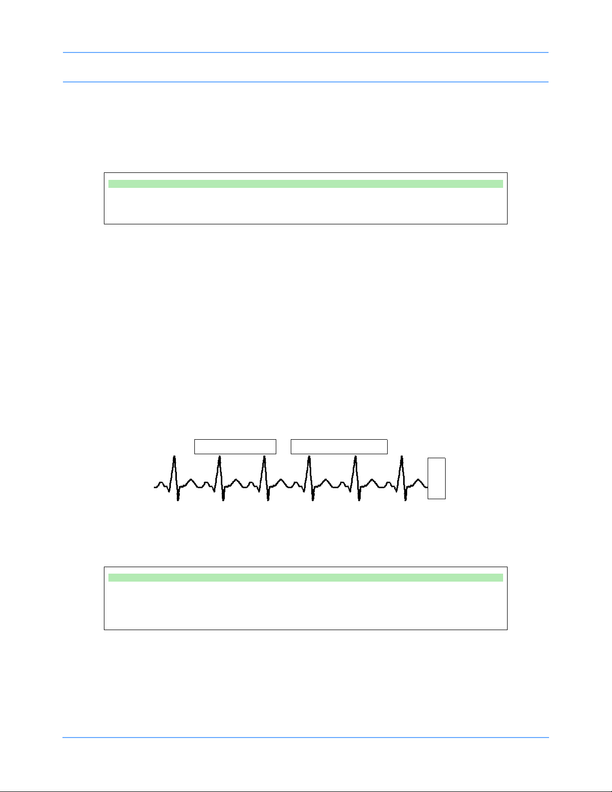
Bedside/Transport Monitors
CST
E
C
G
CANCEL TRANSFER
Module: Jones, B
Monitor: Adams, S
RETRIEVE DATA
Canceling the Data Transfer Before Module Removal
Touch the CANCEL TRANSFER key to clear all data transfer messages and keys from the ECG display zone
and purge previously transferred data from the module. The monitor will then reactivate the TRANSFER DATA
key in the ECG Setup menu.
To cancel data transfer:
• Touch CANCEL TRANSFER.
Retrieving Transfer Data
When you insert the module into the receiving monitor, the monitor displays the RETRIEVE DATA and
CANCEL TRANSFER keys and sounds a low priority alarm tone every five seconds until you either cancel the
data transfer or retrieve the data. The monitor also displays the patient name associated with the data to be
transferred and, if applicable, the patient name associated with the data that currently resides in the monitor.
When you touch the RETRIEVE DATA key, the monitor displays YES and NO keys along with the following
message:
YES purges the monitor's data and retrieves data from the module.
NO cancels this action.
Touch NO to return to the previous screen. Touch YES to transfer the data from the module into the receiving
monitor and purge any data previously stored in that monitor.
Figure 5-7: Retrieving Transfer Data display
To receive transferred data:
• Touch RETRIEVE DATA.
• Touch YES.
Once you initiate data retrieval, the monitor removes all data transfer-related keys from the ECG display zone
and displays the message TRANSFERRING PATIENT DATA INTO MONITOR. When the data retrieval into
the monitor is complete, the monitor displays the message DATA TRANSFER COMPLETED for one minute.
Ultraview Care Network Operations Manual 5-14
Page 95

Bedside/Transport Monitors
When you insert a module loaded with transfer data, you cannot purge a prior patient's data (while data is
being transferred) using the monitor’s Admit or Discharge menus. If you attempt to purge patient data in this
manner, the monitor will display the following message:
Purge is not allowed during transport.
Canceling the Data Transfer After Module Insertion
To cancel a data transfer, touch the CANCEL TRANSFER key. The monitor displays YES and NO keys along
with the following message:
YES purges data previously transferred into the module.
NO cancels this action.
Touch YES to confirm the cancellation of the data transfer and reactivate the TRANSFER DATA key in the
ECG Setup menu. Touch NO to return to the previous screen.
To cancel data transfer:
• Insert module into receiving monitor.
• Touch CANCEL TRANSFER.
• Touch YES.
Battery Status
Battery status conditions are indicated as follows:
Solid Green LED
A solid green LED indicates the external power supply is connected to the AC mains power and does not
indicate the battery charge level. Only a charging cycle or a faulty battery will cause the green LED to flash,
and these conditions only occur when a battery is installed in the monitor.
Flashing Green LED — Battery Charging
A flashing green LED indicates a battery, or batteries, installed in the monitor are being charged and are not
ready to be used.
A flashing LED turns on and off in a constant pattern with no delays. It functions with the monitor powered ON
or OFF. The flashing is different than the battery fault detection flash.
Note:
The green LED will stop flashing and glow solid when the charging cycle is complete.
Ultraview Care Network Operations Manual 5-15
Page 96

Bedside/Transport Monitors
Intermittent Flashing Green LED — Battery Fault Detected
An intermittent flashing green LED indicates that either battery A or battery B is faulty. Faulty batteries are
determined to be batteries which do not hold a charge or batteries which attempt to charge too long.
The intermittent signal will display a solid green LED for one second and then display a flashing LED for one
second in a repeating pattern. An error message is also added to the error log for review by your system
administrator.
To determine whether one battery, or both, are faulty, power the monitor ON using the front panel switch and
observe the display message. The message will display along the bottom of the monitor indicating whether
one, or both, of the batteries are faulty. Replace the faulty battery with the same battery type.
Battery Gauge
The battery gauge is always present in the lower right corner of the display when the monitor is operating on
batteries (powered ON and not plugged into AC power). This gauge indicates the approximate battery
capacity. For example, the gauge will display:
• a fully charged battery
• 3/4 battery charge remaining
• 1/2 battery charge remaining
• 1/4 battery charge remaining
• minimum battery charge remaining
Note:
• Recordings are automatically inhibited when the battery power reaches 1/2 battery charge remaining.
• Recordings drain large amounts of power and could cause the monitor to power OFF without warning.
• When the battery power becomes critically low (approximately 1/4 battery charge remaining), the entire
battery gauge flashes to emphasize this warning. The monitor may power OFF at any time, depending
on monitor loading.
• Upon power OFF, the monitor will cease to function.
Ultraview Care Network Operations Manual 5-16
Page 97

Bedside/Transport Monitors
Wireless Network Interface
The Wireless Network Interface (WNI) provides Ultraview 1030/1050 monitors equipped with the wireless
option to communicate with the Spacelabs Healthcare Ethernet network. This enables the wireless bedside
monitor to communicate with a central station and other networked devices.
The WNI provides wireless transmission of up to five waveforms along with associated numerics, alarms,
trends, arrhythmia, ST, and Flexport Interface Systems data.
Alarm Watch and Remote Trends are not restricted. Bed-to-bed communications enable a bedside to use the
Remote View or Alarm Watch features to view data from other beds on the wireless or hard-wired network.
Outbound Parameters Menu
To view the Outbound Parameters menu, touch the OUTBOUND PARAMETERS key in the Monitor Setup
menu.
When a parameter key is ON, the parameter is available for selection in another monitor’s Remote View menu
and Select Outbound Parameters menu. If two parameters have identical labels, both parameters will
display. The maximum number of parameters that can be set depends upon the monitor’s specific
configuration for wireless networking. When the maximum number of parameters is reached, the remaining
parameters that were not selected become unavailable. The monitor’s default outbound parameter selection is
ECG1 when turned ON.
All parameters, including the parameters that are set to OFF in this menu, are displayed by other monitors that
are set to ALARM WATCH this monitor. If an outbound parameter is set to OFF, all existing remote views for
that parameter will be dropped.
Note:
Setting OTHER to ON selects any unlisted channel types such as VARI, CO, and unlabeled pressures.
To select parameters for display at remote monitors:
• Touch MONITOR SETUP.
• Touch OUTBOUND PARAMETERS.
• Select the parameters you wish to display (up to five).
To change parameters for display at remote monitors:
• Touch MONITOR SETUP.
• Touch OUTBOUND PARAMETERS.
• Deselect the parameter key that you wish to stop displaying.
• Select the parameter you wish to display.
Ultraview Care Network Operations Manual 5-17
Page 98

Bedside/Transport Monitors
Wireless Ethernet Connection
Ultraview 1030/1050 Monitors (Option Z)
In wireless mode, the monitor maintains network communication with a central station through the Wireless
Network Interface (WNI) that is connected to the standard Spacelabs Healthcare hard-wired Ethernet network.
Wireless communication is automatically disabled when the monitor is directly hard-wired to the network using
its network port, and enabled when the hard-wired port is disconnected.
Figure 5-8: Rear panel Ultraview 1030/1050
Ultraview Care Network Operations Manual 5-18
Page 99

Bedside/Transport Monitors
rack mounting
power LED
hardware
(single or double)
90310 front panel
antenna
ã
status LEDs
channel selection
thumbwheel
connectors
connects to
AUI multiport for
wireless network
90310 rear panel
Optional Model 90310 Wireless Network Interface
Figure 5-9: 90310 Wireless Network Interface
Ultraview Care Network Operations Manual 5-19
Page 100

Bedside/Transport Monitors
J1 - external
power supply
connection
external power
supply
DC outlet
cable
Ultraview 1030/1050 Connections
External Power Supply Connection
The connection for the external power supply is shown in Figure 5-10. The green LED on the front panel will
display ON whenever the unit is powered by an external power supply.
Figure 5-10: Ultraview 1030/1050 external power supply connection
The Ultraview 1030/1050 also provides an external Flexport System Interface connection (Figure 5-11).
Ultraview Care Network Operations Manual 5-20
 Loading...