

Page 1

91390
070-2451-01 Rev. F | www.spacelabshealthcare.com October 2014
SERVICE MANUAL
Page 2

91390 QUBE
©2014 Spacelabs Healthcare
All rights reserved. Contents of this publication may not be reproduced in any form without the
written permission of Spacelabs Healthcare. Products of Spacelabs Healthcare are covered by U.S.
and foreign patents and/or pending patents. Printed in U.S.A. Specifications and price change
privileges are reserved.
Spacelabs Healthcare considers itself responsible for the effects on safety, reliability and performance
of the equipment only if:
• assembly operations, re-adjustments, modifications or repairs are carried out by persons
authorized by Spacelabs Healthcare, and
• the electrical installation of the relevant room complies with the requirements of the standard in
force, and
• the equipment is used in accordance with the operations manual.
Spacelabs Healthcare will make available, on request, such circuit diagrams, component part lists,
descriptions, calibration instructions or other information which will assist appropriately qualified
technical personnel to repair those parts of the equipment which are classified by Spacelabs
Healthcare as field repairable.
Spacelabs Healthcare is committed to providing comprehensive customer support beginning with
your initial inquiry through purchase, training, and service for the life of your Spacelabs Healthcare
equipment.
CORPORATE OFFICES
Corporate Headquarters
Spacelabs Healthcare, Inc.
35301 SE Center Street
Snoqualmie, WA 98065
U.S.A.
Telephone: (1) 800-287-7108
Telephone: (1) 425-396-3300
Authorized EC Representative
Spacelabs Healthcare, Ltd.
43 Moray Place
Edinburgh, EH3 6BT
Scotland
Telephone: 44 (0) 131 240 6481
Fax: 44 (0) 131 240 6459
Please refer to http://www.spacelabshealthcare.com/en/company/trademarks for a full listing of
Spacelabs Healthcare trademarks.Other brands and product names used herein are trademarks of
their respective owners.
• Rx Only U.S. Federal law restricts the devices documented herein to sale by or on
the order of a physician.
• Before use, carefully read the instructions, including all warnings and cautions.
www.spacelabshealthcare.com
Page 3

Table of Contents
1Introduction
Overview.............................................................................................................................. 1-1
Warnings, Cautions, and Notes.................................................................................. 1-2
Product Specifications .................................................................................................. 1-3
Electrical Specifications................................................................................................ 1-5
Classification ............................................................................................................. 1-5
Environmental Requirements ..................................................................................... 1-6
Transport and Storage ........................................................................................... 1-6
Operating ................................................................................................................... 1-6
Expected Service Life.................................................................................................... 1-6
Monitor Options............................................................................................................... 1-7
Product Overview ........................................................................................................... 1-7
Monitor Assembly and Module Housing ........................................................... 1-7
External AC Power Supply ................................................................................... 1-8
Batteries ...................................................................................................................... 1-8
Display ................................................................................................................................. 1-8
LCD Display ............................................................................................................... 1-8
Video Subsystem ..................................................................................................... 1-8
Basic Components .......................................................................................................... 1-9
Battery Indicators ................................................................................................... 1-10
Energy Saving Mode (Battery) .......................................................................... 1-13
Signal Strength Indicator ..................................................................................... 1-13
Batteries and Recharging Batteries ........................................................................1-14
To change batteries without interruptions while operating on battery
power ...........................................................................................................................1-15
Battery Power Level .................................................................................................1-15
Architecture......................................................................................................................1-16
Directory of Keys............................................................................................................1-17
2Setup
Unpack the Monitor........................................................................................................ 2-1
Display Assembly ........................................................................................................... 2-2
Input/Output Connections (Internal and External) .......................................... 2-3
Power LED ................................................................................................................ 2-9
Battery Status LED ................................................................................................. 2-9
Alarms ......................................................................................................................... 2-9
Cables ................................................................................................................................. 2-9
Maximum Cable Lengths ...................................................................................... 2-9
SDLC External Devices ......................................................................................... 2-9
SDLC Cable Interconnection ............................................................................... 2-15
SDLC Bus Termination ................................................................................................ 2-15
Alarm Relay for option A .................................................................................... 2-15
Power-ON Test............................................................................................................... 2-17
Configure the Monitor ................................................................................................. 2-17
Privileged Access Menus ..................................................................................... 2-17
www.spacelabshealthcare.com
I-I
Page 4

91390 QUBE
3Theory
CPU PCB ............................................................................................................................. 3-1
Battery Charger and Power Supply Subsection (on CPU PCB) ..................3-4
Li-Ion Batteries................................................................................................................3-5
Battery Switch PCBA for Options B and C .......................................................... 3-7
Monitor Docking PCBA and Connector PCBA.................................................... 3-8
Front Bezel Assembly .................................................................................................. 3-9
Pod Interface PCB........................................................................................................ 3-10
Interconnect PCB ......................................................................................................... 3-10
4 Maintenance
Overview............................................................................................................................. 4-1
Required Test Equipment .................................................................................... 4-2
Mechanical Inspection .................................................................................................. 4-2
Tests for Electrical Safety ........................................................................................... 4-2
Definitions ................................................................................................................. 4-2
Equipment Required ................................................................................................4-3
Ground Resistance ................................................................................................. 4-3
Chassis Leakage Current Tests .......................................................................... 4-4
Patient Lead Leakage Current Tests (Patient Modules) ........................... 4-4
Preventive Maintenance ..............................................................................................4-4
Touchscreen Calibration ...................................................................................... 4-4
To perform touchscreen calibration.................................................................4-4
Functional Tests.............................................................................................................. 4-5
Monitor Self-Test .................................................................................................... 4-5
Monitor Functional Tests ..................................................................................... 4-5
Verification of Monitor Functions ....................................................................... 4-5
Optional Recorder Assembly for Options A and B ......................................4-6
External Alarm Relay Output for Option A ..................................................... 4-6
Ethernet (Wired) ....................................................................................................... 4-7
Assembly/Disassembly Procedures........................................................................ 4-7
Required Tools and Parts .................................................................................... 4-7
Setup for Disassembly .......................................................................................... 4-7
For Option A.............................................................................................................. 4-8
For Options B and C............................................................................................... 4-8
Remove the Bezel Assembly .............................................................................. 4-8
Reassembly ................................................................................................................ 4-10
CPU PCB .................................................................................................................... 4-11
Restore Data to the Monitor .............................................................................. 4-14
Option 1: Exchange the USB Drive PCBAs .................................................... 4-14
Option 2: Format the USB Drive ....................................................................... 4-14
Complete Main Chassis Removal ..................................................................... 4-17
Reinstall the Chassis ............................................................................................. 4-18
SDLC Interface PCB .............................................................................................. 4-19
Speaker ................................................................................................................... 4-20
Mon-Dock PCB ........................................................................................................ 4-21
Battery Door for Option A ................................................................................ 4-22
Connector Board PCB ......................................................................................... 4-23
Replace the Battery Contact PCB .................................................................. 4-24
Replace and Align the Module Door .............................................................. 4-25
Handle ....................................................................................................................... 4-26
Reinstall the Rear Handle Assembly .............................................................. 4-26
Fan ............................................................................................................................. 4-27
Install or Replace the Optional Recorder Assembly ................................ 4-28
To install the recorder......................................................................................... 4-28
To replace the recorder ..................................................................................... 4-29
I-II
www.spacelabshealthcare.com
Page 5

91390 QUBE
Insert Recorder Paper ......................................................................................... 4-29
To insert a roll of paper...................................................................................... 4-29
Dock Connector Covers for Option A ........................................................... 4-29
Removal of Pod Interface PCBA for Options A and B ........................... 4-30
Reinstallation of the Pod Interface PCBA ................................................... 4-30
Docking Station PCBA Replacement Procedures for Option A ................ 4-31
Required Tools and Parts ................................................................................... 4-31
Docking Station ...................................................................................................... 4-31
Replace the Docking Station Latch ................................................................ 4-33
Replace the Docking Station Push Button .................................................. 4-34
Cleaning .......................................................................................................................... 4-35
5Troubleshooting
Overview............................................................................................................................. 5-1
Required Tools and Parts ..................................................................................... 5-2
System Startup................................................................................................................ 5-2
System ........................................................................................................................ 5-3
Power-ON Diagnostics................................................................................................. 5-3
Boot Menu......................................................................................................................... 5-4
To access the Boot menu if the display is functional ................................5-4
Boot Parameters ..................................................................................................... 5-6
Extended Diagnostics................................................................................................... 5-7
Diagnostic Menus ........................................................................................................... 5-8
Main Diagnostic Menu ........................................................................................... 5-8
Individual Diagnostic Menu ................................................................................. 5-9
Memory Menu ......................................................................................................... 5-10
Video Menu ............................................................................................................... 5-11
Error Log............................................................................................................................5-11
View the Error Log ................................................................................................ 5-12
Diagnostics Failure Messages and Error Codes ............................................... 5-14
System Troubleshooting ............................................................................................5-16
Suggested Tools/Test Equipment ................................................................... 5-16
Qube Monitor Does Not Power ON ................................................................. 5-17
Qube Monitor Powers ON, But Fails System Startup ............................... 5-19
High-pitched Tones Heard from the qube Monitor and
No Display is Present ............................................................................................ 5-21
System Software Failure Window Shown
Immediately After System Startup ................................................................. 5-22
Monitor Fails Power-ON Diagnostics ............................................................. 5-23
Troubleshooting Method 1: Use the Touchscreen or Mouse ..................5-23
Troubleshooting Method 2: Use the Remote Terminal—Use When
No Display is Present ............................................................................................. 5-23
Monitor Fails System Functions ...................................................................... 5-24
Batteries/ Battery Charger ..................................................................................5-24
Touchscreen .............................................................................................................5-24
Module does not sign on when installed in an
external module housing .....................................................................................5-24
Module does not sign on when installed
in the monitor for options A and B ..................................................................5-25
Pod does not sign on ......................................................................................... 5-26
Module signs on but parameters do not function ................................... 5-26
Ethernet ................................................................................................................... 5-26
External Alarm Relay for Option A ................................................................. 5-27
Keyboard, Mouse, or Barcode Scanner ......................................................... 5-27
Touchscreen ........................................................................................................... 5-27
Ethernet/Network ................................................................................................ 5-28
External Alarm Relay/Nurse Alert for Option A ........................................ 5-28
www.spacelabshealthcare.com
I-III
Page 6

91390 QUBE
Keyboard, Mouse, or Barcode Scanner ......................................................... 5-29
6Parts
Overview............................................................................................................................. 6-1
Parts List ............................................................................................................................ 6-2
Option A .................................................................................................................... 6-2
Option B ..................................................................................................................... 6-4
Option C ..................................................................................................................... 6-7
Assembly Drawings and Schematics.................................................................... 6-10
7 Glossary
A Appendix A — Electromagnetic Compatibility
Electromagnetic Emissions .........................................................................................A-1
Electromagnetic Immunity .........................................................................................A-2
Separation Distances ................................................................................................... A-3
Mitigation ................................................................................................................... A-4
B Appendix B — Symbols
I-IV
www.spacelabshealthcare.com
Page 7

91390 QUBE
Introduction
Overview
Spacelabs Healthcare designs and manufacturers its products under
good manufacturing practices and in compliance with all applicable
regulatory requirements. To make sure that the product operates
correctly in accordance with these guidelines, trained technicians
using Spacelabs Healthcare authorized replacement parts maintain
this product.
The expected service life of the monitor is seven years from the date
of installation, but its service life can be extended. Many of the
monitor parts are replaceable. Calibration is not required, but
routine safety checks are required. Install a functional battery in the
unit for normal operation. Check the battery periodically and replace
it when necessary.
The qube™ monitor has a 26.2 cm (12.1 inches) LCD display with 1024
x 768 resolution. It has an intuitive user interface and a stylish,
compact design. The monitor includes a single module slot and
supports up to three Flexports® and four USB devices (a mouse,
keyboard, barcode scanner, etc.). Available options include an
integrated recorder and 802.11a/b/g wireless. Dual-battery slots
allow for its use as a transport monitor, as well as at the bedside.
The system has an improved performance and high-resolution LCD
display system. The touchscreen has built-in alarm lights, LED status
indicators (to show the power and battery state), and a power ON/
OFF switch.
www.spacelabshealthcare.com
1-1
Page 8
91390
A
B
C
QUBE
I NTRODUCTION
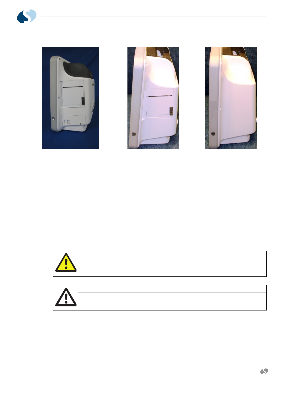
Figure 1-1 91390 qube monitor configuration options
a qube with both printer and battery slots (option A)
b qube with only printer slot (option B)
c qube with no printer or battery slots (option C)
Note:
For more details refer to Table 1-1 on page 4.
Warnings, Cautions, and Notes
Warnings, cautions, and notes are used throughout this manual. The
formats below show how warning, cautions, and notes are identified.
Warning:
Alerts the user to potentially serious outcomes (death, injury, or serious
adverse events) to the patient or user.
Caution:
Alerts the user to actions to be taken to avoid non-serious injury to the
patient or user, or to adverse effects to the device.
1-2
Note:
Failure to observe notifications can result in unexpected
outcomes.
www.spacelabshealthcare.com
Page 9

91390 QUBE
Product Specifications
Refer to Basic Components on page 1-9 for more information.
Product Specifications
Height 26.2 cm 10.3 inches
Width 31.5 cm 12.4 inches
Depth 13.2 cm 5.2 inches
Weight 4.1 kg 9 lbs
Color thin film transistor (TFT) liquid crystal display (LCD), resistive touchscreen
Resolution 1024 x 768 pixels
I NTRODUCTION
Physical Dimensions
Display
Size- wide
- high
24.6 cm
18.4 cm
9.7 inches
7.3 i nc he s
Printer
Printing Method* Thermal array print head
Paper Heat-sensitive paper roll, 50 mm wide x 30 m long
Resolution Eight dots per mm (vertical) and 32 dots per mm
(horizontal) at 25 mm per second sweep speed
Prints Manual and automatic alarm recordings for waveforms,
vital sign data, trends, calculations, and full annotations
are included
Controls Continuous, Stop Recording, Compressed, Paper Advance
Indicators Paper out, Unit off
Sweep Speed Various speeds are available under module control.
* May not be included in the qube configuration option package.
For more details on configuration options, refer to Qube
Configuration Options on page 1-4.
www.spacelabshealthcare.com
1-3
Page 10
91390
AB C
QUBE
I NTRODUCTION
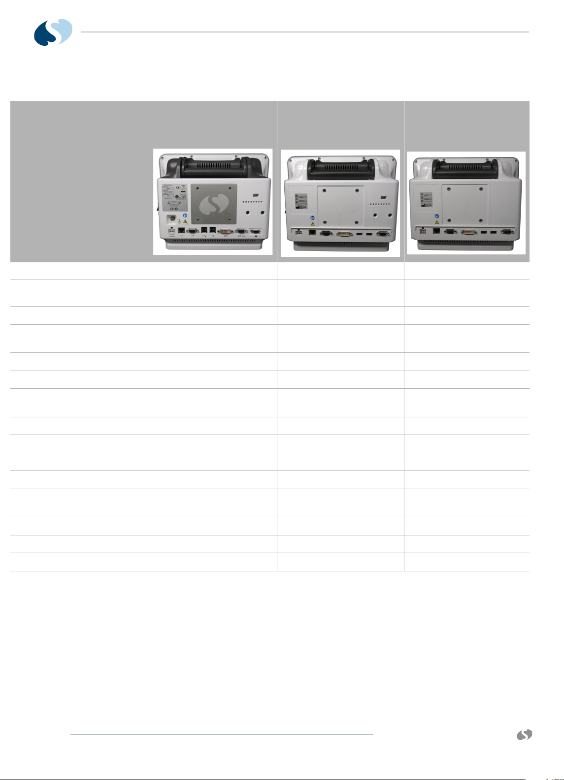
Table 1-1 Qube Configuration Options
Connectors
Internal Recorder Slot 1 on right panel 1 on right panel not included
Front Integrated Alarm Light 1 on top, front, and back of
Docking Station connection included not included not included
Integrated or Hot Swappable
Battery Slot
Equipotential Terminal 1 on rear panel not included not included
DC Power Input 1 on rear panel 1 on rear panel 1 on rear panel
Ethernet 10/100 Base T
Connection
Serial Port 1 on rear panel 1 on rear panel 1 on rear panel
USB Ports 4 on rear panel 2 on rear panel 2 on rear panel
Video Output, DVI-D 1 on rear panel 1 on rear panel 1 on rear panel
SDLC Port 1 on rear panel 1 on rear panel 1 on rear panel
Remote Alarm Output-Nurse
Alert
Module Slot 1 on left panel 1 on left panel 1 on left panel
POD Connection 1 on rear panel 1 on rear panel not included
Power On/Off Button on right side of display on right side of display on right side of display
2 Lithium-Ion (Li-Ion), right
side below printer slot
display
1 on rear panel 1 on rear panel 1 on rear panel
1 on rear panel not included not included
1 on front of display not included
2 Lithium-Ion (Li-Ion), fixed
non-removable
1 Lithium-Ion (Li-Ion), fixed
non-removable
1-4
www.spacelabshealthcare.com
Page 11
91390 QUBE
Electrical Specifications
Classification
Warning:
• Use designated power supply only.
• Do not modify this equipment without the authorization of the
manufacturer.
• To avoid electric shock, connect this equipment only to a supply mains
with a protective earth conductor.
• Class I - Requires outlet with Protective Earth (safety ground)
conductor
• Mains Power: 100 - 240 VAC, 50 - 60 Hz, 3 - 1.5 A
• Rated for continuous operation
• Isolation: Leakage currents meet ANSI/AAMI ES 60601-1, CSA
C22.2 No. 60601-1, and IEC 60601-1.
I NTRODUCTION
• Batteries: (For configuration options, refer to Qube
Configuration Options on page 1-4).
1 10.8 Volt (7.2-Ah Li-ion) smart battery. One battery
provides approximately 4 hours of operation. Two
batteries allow up to approximately 8 hours of operation.
There are approximately 300 charge/discharge cycles of
operation for each battery.
2 10.8 Volt (4.8-Ah Li-ion) smart battery. One battery
provides approximately 2 hours of operation. Two
batteries allow up to approximately 4 hours of operation.
There are approximately 300 charge/discharge cycles of
operation for each battery.
3 10.8 Volt (4.8-Ah Li-ion) smart battery. One battery
provides approximately 2 hours of operation. There are
approximately 300 charge/discharge cycles of operation
for each battery.
Note:
One battery charges in approximately two hours. Two batteries
charge in approximately four hours.
www.spacelabshealthcare.com
1-5
Page 12

91390
QUBE
Environmental Requirements
Transport and Storage
Temperature: -25º to 60º C (-13º to 140º F)
Humidity: 95% (non-condensing)
Altitude: 0 to 12,192 meters (0 to 40,000 feet)
Operating
Operating Temperature: 0º to 40º C (32º to 104º F)
Humidity: 95% (non-condensing)
Altitude: 0 to 4,572 meters (0 to 15,000 feet)
Expected Service Life
I NTRODUCTION
The expected service life is seven years from the date of first use.
Spacelabs Healthcare recommends regular replacement of the
following parts to extend service life:
•LCD
• LCD backlights
• batteries
•fan
Replace the listed items especially if you use them beyond the
service life range. Perform safety checks and maintenance of the
monitor on regular schedules. Spacelabs Healthcare offers a
refurbishment program for equipment that has passed its expected
service life. Contact your local service representative for more
information.
To protect the environment, properly dispose of all
batteries, electronic assemblies, plastics, and metals.
Follow your internal procedures or local (provincial)
laws regarding disposal or recycling.
1-6
www.spacelabshealthcare.com
Page 13

91390 QUBE
Monitor Options
I NTRODUCTION
Table 1-2 91390 Monitor Options
Option Definition
D Perioperative: provides customizable, user-specific display
setups and start case and end case functions
N Vital Signs Calculations (Hemodynamics, Oxygenation,
Ventilation, and Renal)
Q Data Shuttle
information
R Patient Data Logger (PDL); presents an ASCII data stream of
patient name and vital sign data to the serial port in a predefined format
S Dynamic Network Access (DNA); Spacelabs Healthcare
proprietary version of the Citrix ICA Client connects and
interacts with remote applications hosted on Citrix servers.
Citrix server software and other associated licenses and
applications must be purchased separately.
®
supports the transfer for up to 96 hours of trend
U Printer; one printer slot, refer to the product specifications
section for details
V Full View; supports simultaneous display of 12 ECG leads
W Full Bed Review; provides a multi-parameter view for any
monitored patient on the network (up to seven waveforms)
X Wireless; 802.11a/b/g
Product Overview
Monitor Assembly and Module Housing
The monitor is a portable product that provides physical mounting,
electrical connection, and power for a plug-in module. It also
provides power and SDLC I/O for externally connected flexports
and other devices. The monitor provides interfaces for:
• internal and optional external displays
• connections for a mouse, keyboard, barcode reader using USB
• remote control through IR remote control: option A
(SL number 90360-01)
www.spacelabshealthcare.com
• the required video signals for an external display
A separate external power supply powers the monitor. All voltage
conversion that is required to support the modules and the internal
electronics is provided inside the product. Provisions are provided
for detection of an AC line failure to provide for an orderly power
off.
1-7
Page 14

91390
QUBE
External AC Power Supply
The external AC supply that powers the monitor meets worldwide
safety and EMC requirements. The external AC supply provides
20 VDC. The external AC supply provides 20 VDC at 4.5 Amps. The
external power supply (an AC/DC converter) has a 6pin rectangular
connector (P/N 119-0552-00).
Batteries
The option A monitor accommodates the use of two removable
internal batteries. At least one battery must be installed for normal
operation.
The option B monitor has two fixed (non-removable) batteries. The
option C monitor has one fixed (non-removable) battery.
For more information, refer to Batteries and Recharging Batteries on
page 1-14.
Display
I NTRODUCTION
LCD Display
Video Subsystem
For options A and B, the LCD display assembly provides multicolor
visual alarm notification based on the severity of the alarm. The
software controls the operation of the alarm lights. There is a red
light for high priority, a yellow light for medium priority, and a cyan
light for low priority and technical alarms.
The alarm lights are visible directly above the display screen on
options A and B, and on the rear of the monitor above the handle on
option A.
The primary display is a 12.1-inch color TFT LCD. The video interface
is 24-bit Flat Panel Display Link (FPD-Link) using LVDS.
The display has an LED backlight supplied with 12-volt power. A
PWM control signal controls the brightness of the LED backlight.
The power supply microcontroller generates the PWM control signal
under the direction of the host application.
The secondary display is an external monitor compatible with
standard Digital Visual Interface (DVI) signaling. The interface is
DVI-D which supports digital-only, single-link.
The secondary display has the same image and resolution as the
primary display.
1-8
www.spacelabshealthcare.com
Page 15
91390 QUBE
1
2b
2a
3
3
4
Parameter Minimum Typical Maximum Unit Remarks
Video Clock Rate 60.0 15.385 68.0 nS 65-MHz typ.
Horizontal Rate 19.67 20.676 22.4 uS 48.363-KHz typ.
Vertical Rate 13.3 16.666 18.5 mS 60-Hz typ.
Basic Components
I NTRODUCTION
• Resolution 1024 x 768
• Active Lines 768
• Active Pixels 1024
Table 1-3 Display Specifications
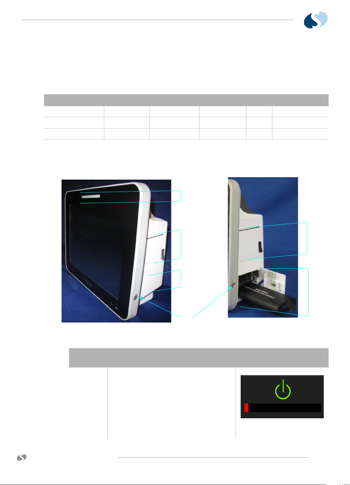
Callout
Number
1 Power On/Off Button- Press and hold the
www.spacelabshealthcare.com
Figure 1-2 Front and Right Side of the Qube Option A
Description Symbol
power button for at least three seconds to turn
the monitor off. System shutdown progress is
shown below the green power symbol.
Note:
Hold the power On/Off for 3 seconds,
or the monitor will not power off.
Figure 1-3 System shutdown
progress
1-9
Page 16
91390
QUBE
I NTRODUCTION
Callout
Number
2a Integrated Battery Slot closed* Refer to To change batteries
2b Hot Swappable Battery Slot open with battery
3 Internal Recorder Slot* N/A
4 Front Integrated Alarm Light* N/A
Description Symbol
partially pulled out.*
Battery Indicators
Warning:
At least one battery should always be installed in the monitor. The
battery is a critical component of the electrical system. It improves EMC
immunity performance when the monitor is connected to the AC power.
without interruptions while
operating on battery power on
page 1-15 for details.
Refer to To change batteries
without interruptions while
operating on battery power on
page 1-15 for details.
* Not all of the qube configuration options include these items.
For more details, refer to Qube Configuration Options on
page 1-4.
Notes:
• The battery provides power to the monitor when it is
separated from the AC power.
• Batteries charge when the monitor is connected to the AC
power.
• The monitor auto-switches to battery operation when
separated from the AC power.
• Remove batteries if the monitor is not likely to be used for
some time.
• Remove batteries from the monitor before storage or
shipment.
1-10
www.spacelabshealthcare.com
Page 17
91390 QUBE
2
1
I NTRODUCTION
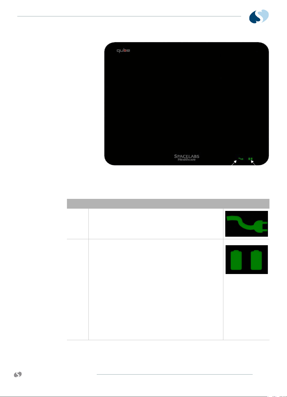
Figure 1-4 Battery charger and AC/DC power indicators
Table 1-4 Power Indicators (only shown when AC is connected)
Description Symbol on panel
1 AC/DC Power Indicator - External power supply is connected
to the monitor and the AC mains. When the AC power
indicator comes on, the connection is good.
Refer to Figure 1-4.
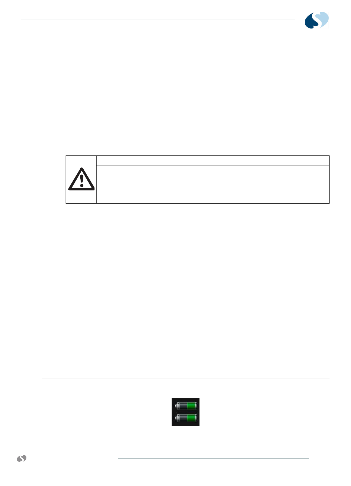
2 Battery Charge Status Indicator-
Shown if a battery is present. The left light shows if the top
battery is installed. The right light shows if the bottom
battery is installed.
Flashing (rate of 1 second on and 1 second off) shows the
battery is charging.
Steady ON shows the battery is charged.
Flashing, rapid or erratic shows the battery is faulty and must
be replaced.
Refer to Figure 1-4.
Note:
The option C monitor has one battery, so only one
battery charge indicator shows.
www.spacelabshealthcare.com
1-11
Page 18
91390
1
12
11
2
10
98 7 66 5 4 3
QUBE
I NTRODUCTION
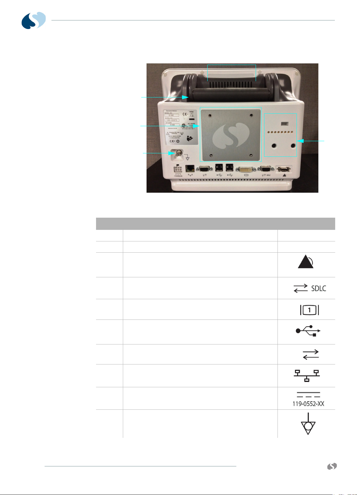
Figure 1-5 Back Panel of Qube*
Description Symbol on panel
1 Integrated Alarm Light*N/A
2 POD Connection such as Capnography Pod.* N/A
3 Remote Alarm Output - Nurse Alert*
Refer to Alarm Relay for option A on page 2-15 for
details.
4 SDLC Ports
Refer to SDLC Bus Termination on page 2-15 for details.
5 Video Output, DVI-D
Digital only
6 USB Ports
qty= 4 for option A
qty= 2 for options B and C
7 Serial Port
8 Ethernet 10/100 Base T Connection
9 DC Power Input
119-0552-00
1-12
10 Equipotential Terminal*
used for grounding the monitor
www.spacelabshealthcare.com
Page 19
91390 QUBE
Description Symbol on panel
11 75 mm VESA Mounting Pattern N/A
12 Handle N/A
* Not all of the qube configuration options include these items.
For more details, refer to Qube Configuration Options on
page 1-4.
Energy Saving Mode (Battery)
The qube has an energy saving mode. Energy saving mode lets the
monitor dim after 30 seconds of no interaction. If you enable this
mode, do not touch the monitor for 30 seconds to see it dim. The
monitor does not dim if you use a mouse with the monitor or an
alarm event occurs. Refer to the XPREZZON and qube System
Administration Manual (P/N 070-2380-xx) for more details.
I NTRODUCTION
Signal Strength Indicator
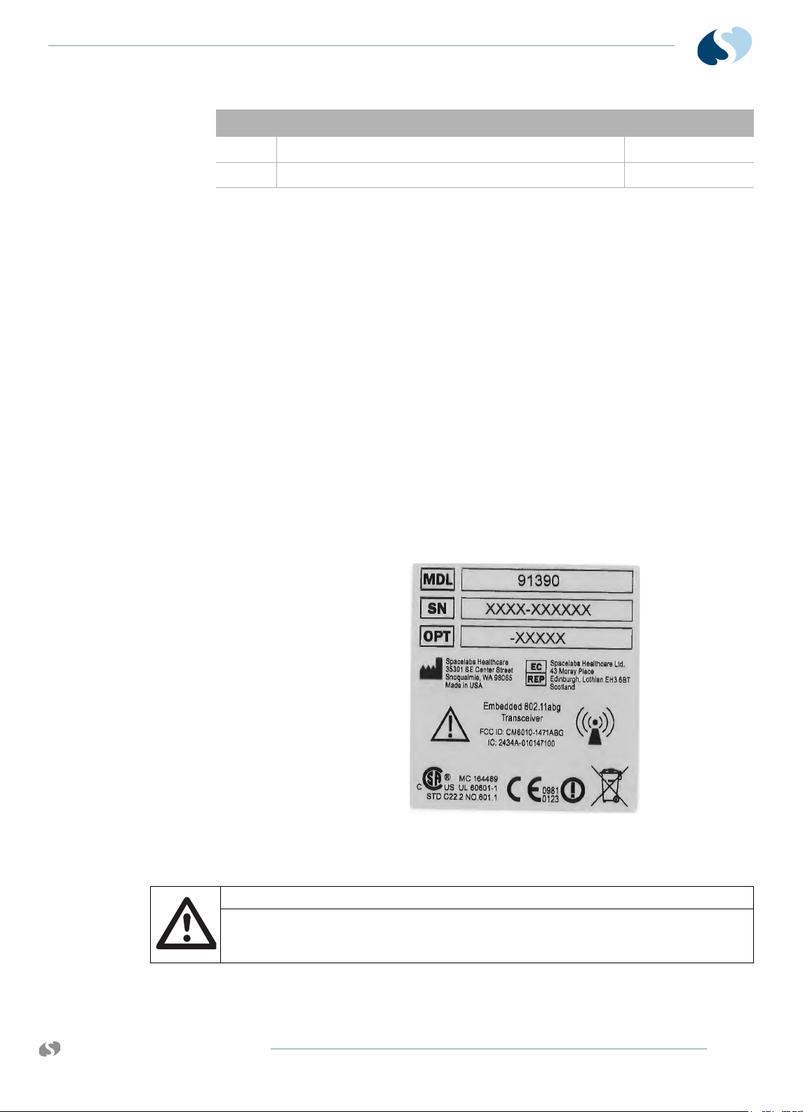
Monitors equipped with option X (an embedded 802.11a/b/g
transceiver) are labeled at the factory. A separate label is provided
with the option X kit for field installation (Refer to Figure 1-6).
Figure 1-6 P/N 334-6134-01, LABEL,MOD,S/
N,OPT,REG,WIRELESS,91390
Caution:
www.spacelabshealthcare.com
The only other indication for the presence of option X is the wireless field
strength icon that shows when the ethernet cable is removed and the
wireless option is enabled (Refer to Figure 1-7).
1-13
Page 20
91390
QUBE
I NTRODUCTION
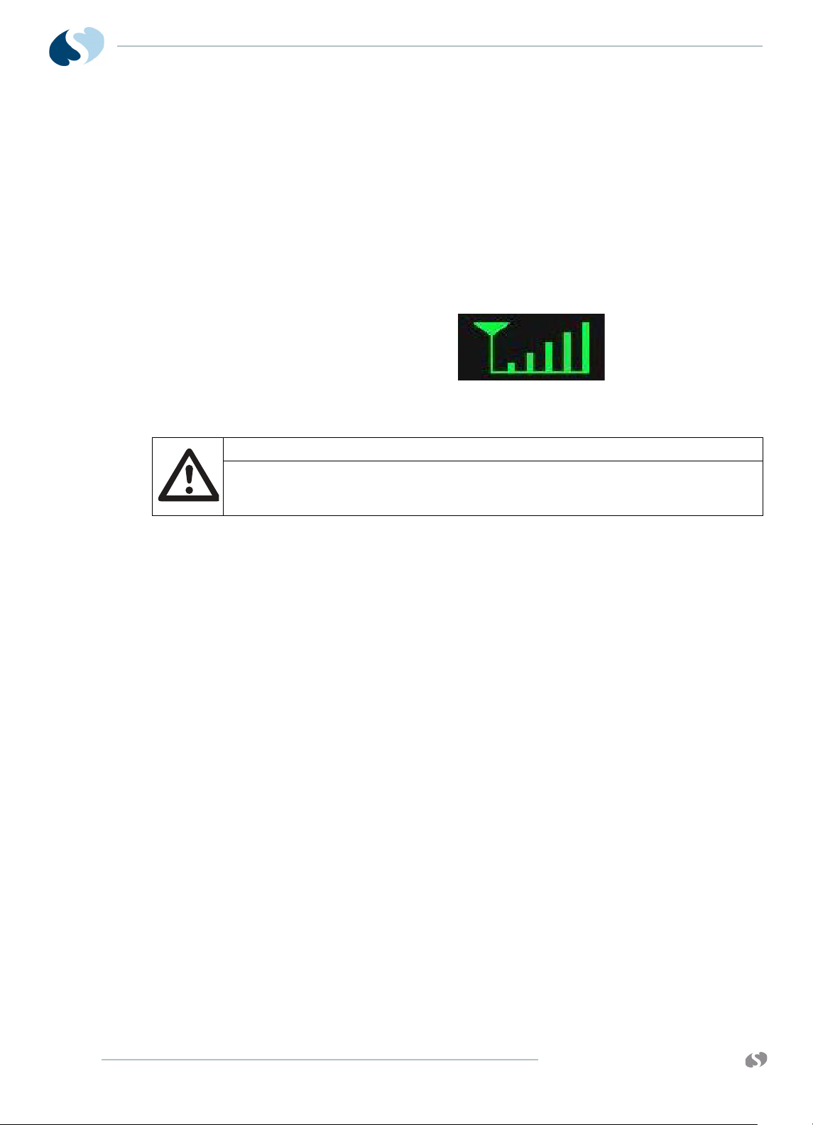
Monitors with wireless network communication show a wireless
signal strength indicator while they communicate over the wireless
network. To use the wireless feature, disconnect the wired network
connector. Not all qube monitors include the wireless option.
The wireless signal strength shows between the Admit Patient
button and alarm buttons. The signal strength shows a green
antenna with vertical bars on a black background. The number of
bars show the strength level. One bar is low strength. The strongest
signal is five bars. The signal changes to yellow when the network
connection is lost. For more information, refer to the XPREZZON and
qube System Administration Manual (P/N 070-2380-xx).
Figure 1-7 Wireless signal strength indication
Caution:
Signal strength and radio system congestion can contribute to waveform
gaps over the wireless network. Should this be a persistent issue, consult
with a Spacelabs Healthcare field service representative.
Batteries and Recharging Batteries
For option A, the monitor uses smart batteries, and at least one
battery must be installed for normal operations. If it uses two fully
charged batteries in a standard configuration, the monitor operates
up to eight (8) hours. With one fully-charged battery in a standard
configuration, the monitor operates up to four (4) hours.
The battery icon shows if the batteries are inserted. This icon shows
how much charge the batteries have. The icon updates every six
seconds and is to the left of the audio icon on the lower-right
section of the monitor. Refer to Table 1-5 on page 1-15.
Charge temperature limits are ≤80% RH.
The battery must be capable of continuous charge at 12.6 V. To
charge the battery, only use a dedicated level II or level III smart
battery charger. When you use a level II or level III smart battery
charger, the battery requests the appropriate charging voltage and
current.
The FULLY_CHARGED bit in the Battery Status is set when the
charging current tapers down to under 240 µA, while charging at
12.6 V.
Notes:
• The battery life greatly depends on usage, age, and the
environment. The battery operating life decreases over time.
1-14
www.spacelabshealthcare.com
Page 21
91390 QUBE
I NTRODUCTION
• One battery charges in approximately two hours, and two
batteries charge in approximately four hours.
The option B monitor operates for up to four hours with two fully
charged batteries and standard configuration. With a single fully
charged battery and standard configuration, the monitor operates
for up to two hours. The battery is not removable from the monitor.
The option C monitor operates for up to two hours with a single
fully-charged batteries and standard configuration. The battery is
not removable from the monitor.
Note:
For options B and C monitors, only one battery icon shows on the
main screen.
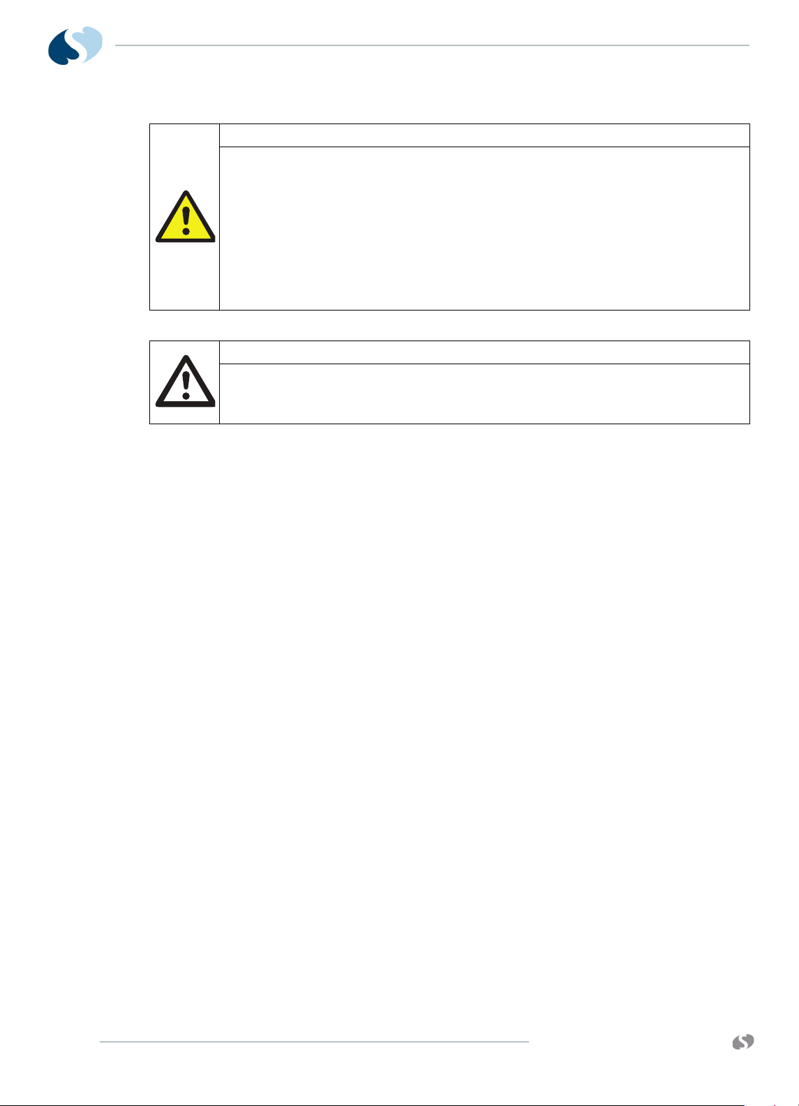
Caution:
The qube monitor and smart rechargeable Li-Ion batteries and cells do
not overheat, they have internal protection devices. Overexposure to heat
will activate one of these devices and may permanently disable the
battery. If this happens, contact Spacelabs Healthcare to purchase a
replacement battery.
Battery Power Level
A green color on the battery icon shows the current charge level of the battery.
A yellow or red color shows that the battery power is at a critically low level. If the battery power is critically
To change batteries without interruptions while operating on battery power
1 If operating on top battery (battery A), remove lower battery
(battery B).
2 Install new battery (battery C) into the lower battery slot.
3 To make sure that the operation of the new battery is correct,
look at the battery indicator lights (Refer to Table 1-5 on page 1-
15).
4 Remove battery A. Replace it with another new battery.
Extended use of the batteries depletes the battery power. To
prevent patient data loss, the qube monitor watches the battery
power level that remains. As power gets low, the monitor warns the
user about low battery power and inhibits the use of the internal
recorder to extend run time.
Table 1-5 Battery power level messages and tones
low, recharge the battery.
www.spacelabshealthcare.com
1-15
Page 22
91390
QUBE
I NTRODUCTION
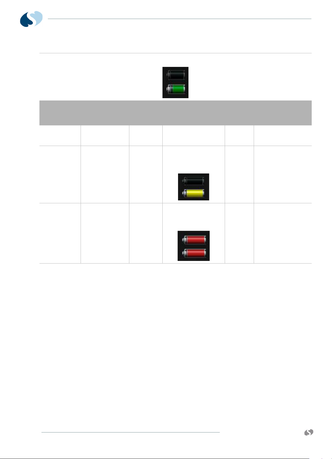
Table 1-5 Battery power level messages and tones
A dark gray outline around a solid black battery icon shows that a battery slot is empty. After you install a
battery into the slot, the battery icon shows a white outline and the current charge level of the battery..
Power level
(one battery)
11% 6% Yes The message shown
6% 3% Yes Yellow flashing battery
4% 2% With or
Power level
(two batteries)
Recorder
attached
without
recorder
** Time can be shorter or longer depending on the battery performance.
Warning description
lets you know that the
recordings stop.
icon is shown. Message
shown lets you know
the recordings are
stopped.
Red flashing battery
icon is shown. Message
shows that the battery
power level is critically
low.
Audible
tones
soft 30 minutes
soft 15 minutes
loud 10 minutes
**Approximate
time before device
shuts down
Architecture
1-16
The basic internal architecture, or Printed Circuit Board Assembly
(PCBA), of the qube monitor, is shown in the System Block Diagram
(Drawing 1, Sheet 1). Refer to the drawings section of this manual for
more information.
The hardware for the monitor has the following features built around
the Microprocessor Controller (MPC) MPC8270:
•10/100BaseT Ethernet
• 266-MHz maximum CPU speed
• 66-MHz system bus for memories
• 32 MB Flash, 64 MB of SDRAM, and 2 MB SRAM
• 3.3-V logic design
• PCI2.2 at 33 MHz
www.spacelabshealthcare.com
Page 23

91390 QUBE
Directory of Keys
I NTRODUCTION
• USB support (USB2)
• Optional mini-PCI Wireless interface for 802.11a/b/g devices
• External Video (Digital DVI)
• 5-wire resistive touchscreen
• Barcode Reader support (through USB port)
• Optional Remote IR Keypad support: option A
• Multilevel/Multicolor alarm indicator: option A
For a comprehensive directory of keys and explanations, refer to the
XPREZZON and qube System Administration Manual.
www.spacelabshealthcare.com
1-17
Page 24

91390
QUBE
I NTRODUCTION
1-18
www.spacelabshealthcare.com
Page 25

91390 QUBE
Setup
Unpack the Monitor
Standard contents in the box includes:
•91390 monitor
• Country-specific power cord
• Battery (option A: one, second is optional)
• External DC power supply
Make sure that there is a packing list for optional accessories. Keep
at least one shipping box and its packing materials in case you must
return items, or if the monitor requires factory service.
Notes:
• When you remove items from the shipping containers, make
sure that you remove ALL components from each container.
• To determine the contents, refer to the packing list for your
individual order.
• When you receive the equipment, complete a detailed
inventory to make sure that the equipment you received
matches your order. This inventory must include serial
numbers, model numbers, and all options and cables received.
Carefully examine these items for shipping damage. If you find
any damage, immediately notify the freight company and
Spacelabs Healthcare.
www.spacelabshealthcare.com
2-1
Page 26
91390
QUBE
S ETUP
Warning:
• The qube monitor and smart rechargeable Li-Ion batteries and cells do
not overheat, they have internal protection devices. Overexposure to
heat will activate one of these devices and may permanently disable
the battery. If this happens, contact Spacelabs Healthcare to purchase
a replacement battery.
• Failure to properly configure this device prior to network connection
may alter network time or corrupt patient data.
• Do not mount the monitor or docking station directly above the
patient.
Caution:
• If liquid spills onto the docking station, make sure that the docking
station is checked by service staff before you use it again.
• Observe precautions for handling electrostatic-sensitive devices!
Notes:
• Before you touch electrostatic-sensitive electronic
components, follow proper anti-static procedures, including
the use of an ESD wrist band and mat. An electrostatic
discharge from your fingers can permanently damage
electronic components and cause latent failures.
• All static-sensitive electronic components are packaged in
static-shielding bags. Keep the bag in case you must
repackage the component to store it or return it to Spacelabs
Healthcare for any reason.
• For options B and C, the battery switch must be set to ON
prior to use.
Display Assembly
2-2
Display features:
• LCD TFT Display, 12.1" with backlight control
• 5 Wire Resistive Touch screen
• RED, YELLOW, and CYAN LED bars: options A and B
• Remote control IR receiver: option A
• Power and Battery status indicators (LEDs)
•Power switch
www.spacelabshealthcare.com
Page 27
91390 QUBE
S ETUP
Input/Output Connections (Internal and External)
This section defines the I/O connections.
The back panel includes:
•DC Input Power connector
• SDLC (Flexport) connector
• Pod interface connector (SDLC protocol): options A and B
• Remote Nurse Alert connector: option A
• Second display connector (DVI-D)
• RS232 serial connector
• USB ports: Four for option A. Two for options B and C.Ethernet
10/100 base T, RJ45 connector.
Warning:
Data interface connectors on this device are Ground (Earth) referenced!
- Only connect this device to other medical equipment suitable for
use in the Patient Vicinity.
Pod Interface Connector - 8
CONTACT PADS for options A
and B
- Check Ground (Earth) Leakage after connecting data interface
cables.
The left side supports the module slot. The right side accommodates
two lithium batteries and the recorder.
The pod interface SDLC I/O connector (P300) is on the back panel
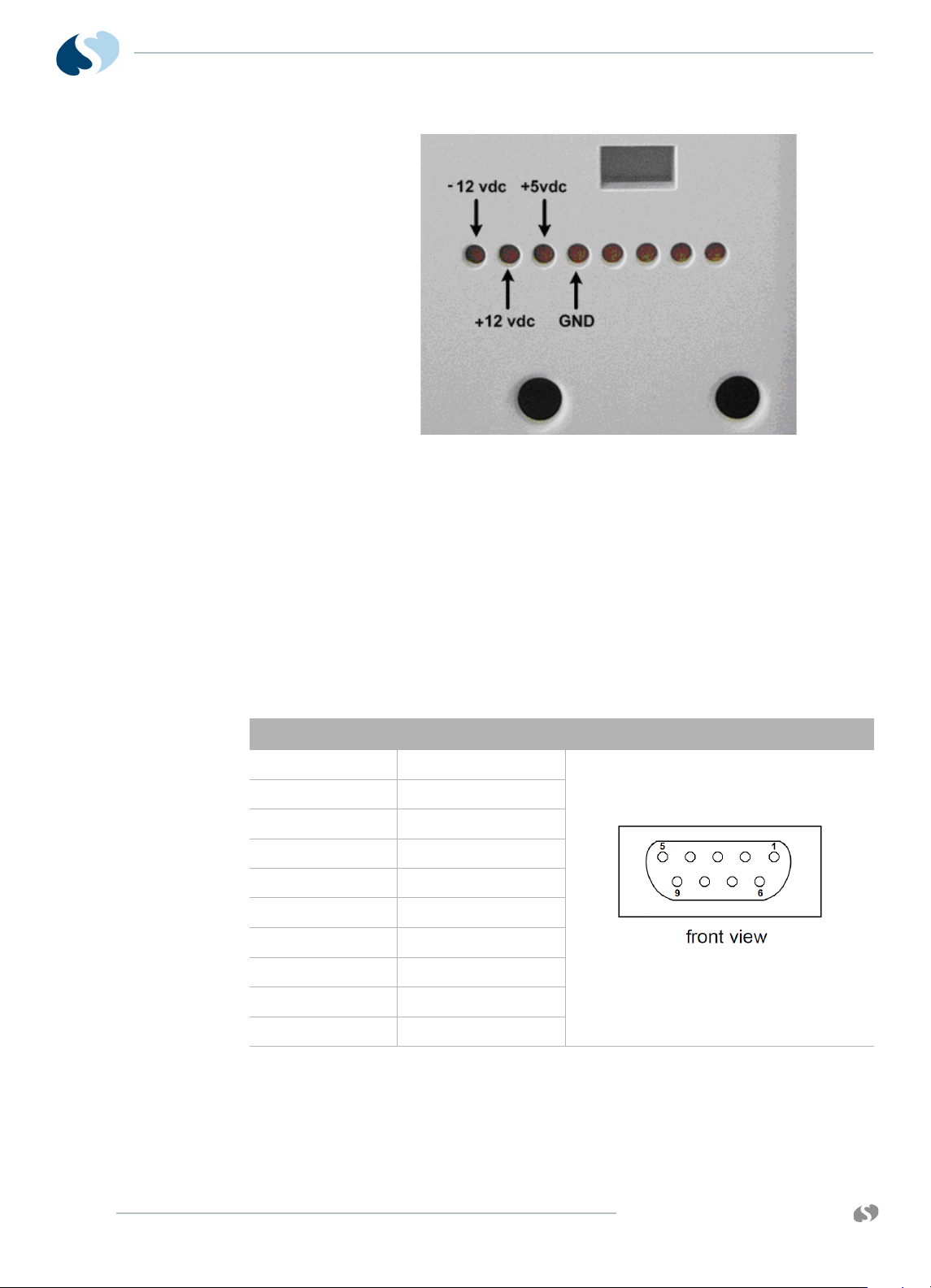
of the monitor. The pinout for this connector is designed as follows:
Table 2-1 Pinout for Pod Interface Connectors
Pin # Function
PIN 1 SDLC_DAT+
PIN 2 SDLC_DAT-
PIN 3 SDLC_CLK+
PIN 4 SDLC_ CLK +
PIN 5 GROUND
PIN 6 +5 VDC
PIN 7 +12 VDC
PIN 8 -12 VDC
www.spacelabshealthcare.com
2-3
Page 28
91390
QUBE
S ETUP
Figure 2-1 Voltage test points on pod connector
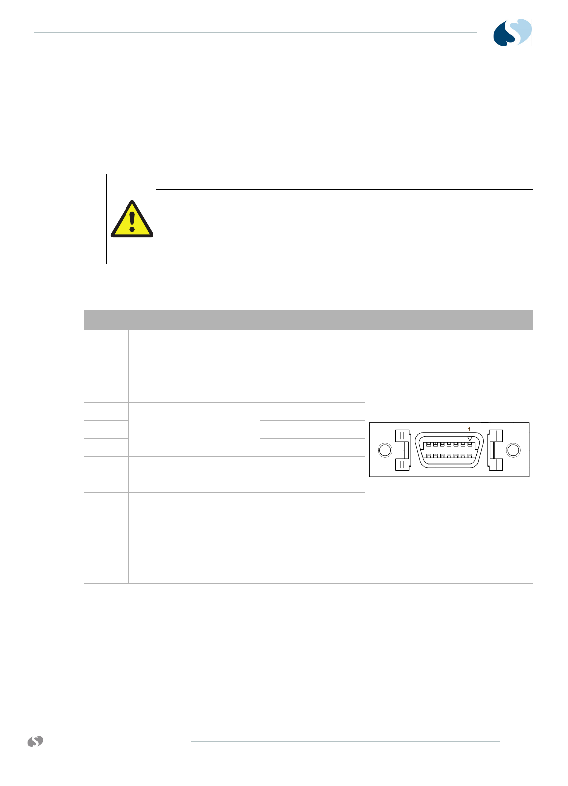
SDLC I/O Connector - DB9
Female
Pin # Function Image
The Flexport SDLC I/O connector is on the back panel. The SDLC
clock frequency is approximately 2 MHz. Docked, (P506) becomes
the SDLC I/O. This interface is electrically compatible with the EIARS485/RS422 standard. The communications protocol is derived
from the IBM Synchronous Data Link Control specification, and uses
its Non-Switched Multipoint Half-Duplex configuration. This
interface is compatible with all of Spacelabs Healthcare Flexports.
The CPU board always provides the SDLC clock. The SDLC clock
frequency is 3.7847 MHz ±100 ppm. The pinout for this connector is
as follows:
Table 2-2 Pinout for external SDLC connector
PIN 1 RTN
PIN 2 SDLC DATA +
PIN 3 SDLC DATA -
PIN 4 + 5V
PIN 5 + 12V
PIN 6 SDLC CLK +
PIN 7 SDLC CLK -
2-4
PIN 8 -12V
PIN 9 RTN
www.spacelabshealthcare.com
Page 29
91390 QUBE
S ETUP
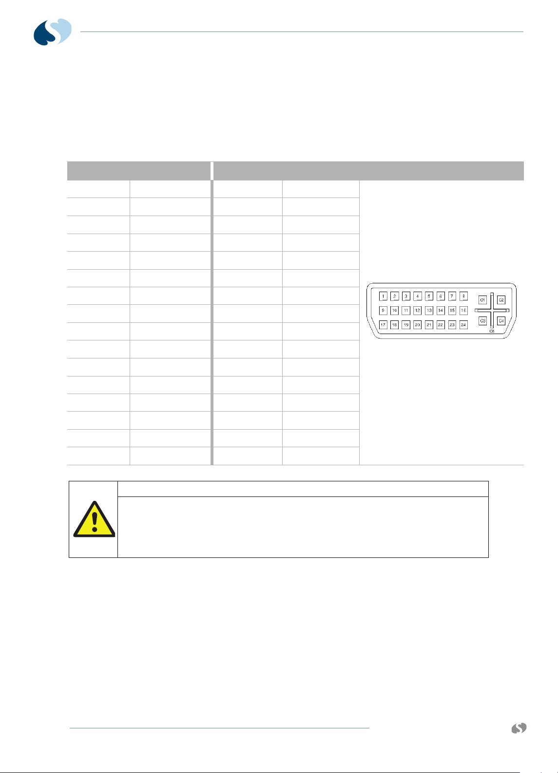
Remote Nurse Alert Connector 14 Pin for option A
Warning:
Data interface connectors on this device are Ground (Earth) referenced!
Pin
1 Alarm 0 (high priority) Common
2 Normally Closed
Alarm Circuit Meaning Image
The Remote Nurse Alert connector is primarily designed to provide
a contact closure to the outside world to indicate an alarm
condition. The nurse alert output provides +12V, return and three
sets of relay contacts. There is one set of relay contacts for each of
the three alarm levels. Each set of relay contacts consists of a
common normally open (NO) and normally closed (NC). Each
contact is able to carry at least 150 mA continuous.
- Only connect this device to other medical equipment suitable for
use in the Patient Vicinity.
- Check Ground (Earth) Leakage after connecting data interface
cables.
The pinout for this connector is as follows:
Table 2-3 Connector Pinouts
3Normally Open
4GND
5 Alarm 1 (medium priority) Normally Closed
6Normally Open
7 Common
8GND
9 +12 V, 140 μA
10 GND
11 GND
12 Alarm 2 (low priority) Normally Open
13 Common
14 Normally Closed
www.spacelabshealthcare.com
2-5
Page 30
91390
QUBE
S ETUP
DVI Digital Video Output
Connector - 29 PIN DVI-D
Pin # Function Pin # Function Image
PIN 1 TX2N PIN 17 TX0N
PIN 2 TX2P
PIN 3 RTN
PIN 4 NC
PIN 5 NC PIN 21 NC
PIN 6 DDC_CLK
PIN 7 DDC_DAT
PIN 8 NC
PIN 9 TX1N
PIN 10 TX1P
This DVI-D video connector (P207) is an output to an optional
secondary display. The voltage levels on these connectors are
compatible with the EIA-RS343A standard. The video timing
supports the qube monitor itself. The pinout for this connector is as
follows:
Table 2-4 Pinout for External DVI Connector
PIN 18 TX0P
PIN 19 RTN
PIN 20 NC
PIN 22 RTN
PIN 23 TXCP
PIN 24 TXCN
PIN C1 NC
PIN C2 NC
PIN 11 RTN
PIN 12 NC
PIN 13 NC
PIN 14 +5VDC
PIN 15 RTN
PIN 16 NC
Warning:
Only connect to an approved medical device.
- Common computer equipment may exceed safe leakage current
limits in the patient vicinity.
- Check leakage currents after equipment is interconnected.
PIN C3 NC
PIN C4 NC
PIN C5A RTN
PIN C5B RTN
PIN 31 SHIELD
PIN 32 SHIELD
2-6
www.spacelabshealthcare.com
Page 31

91390 QUBE
S ETUP
DC Power Input Connector There is one DC Power input connector (P204). on the back of the
unit. The DC Power Input connector mates to an external AC/DC
converter supply. The pinouts for this connector are as follows:
Table 2-5 Pinout for the DC Power Input Connector
Pin # Function Image
PIN 1 Ground
PIN 2 + V
PIN 3 + V
PIN 4 RTN
PIN 5 RTN
PIN 6 Ground
Serial I/O Connector - DB9
Female
The Serial I/O connector is on the back of the unit and provides RS232 access to the CPU Board. This interface conforms to the EIARS232 standard. The baud rate and the number of start, stop, and
parity bits are software programmable.
This connector is also used to support the Sysgen Data Key function,
which controls access to menus to enable and disable qube options.
The pinouts for this connector are as follows:
Table 2-6 Pinout for Serial Port
Pin # Function Image
PIN 1 CD
PIN 2 RXD
PIN 3 TXD
PIN 4 DTR
PIN 5 RTN
PIN 6 DSR
PIN 7 RTS
PIN 8 CTS
PIN 9 NC
www.spacelabshealthcare.com
2-7
Page 32

91390
QUBE
S ETUP
USB Connectors (4 for option A,
2 for options B and C)
Port A Top PIN A1 A: VBUS (+5V)
Port B Bottom PIN B1 B: VBUS (+5V)
10/100BASE-T Ethernet
Connector - RJ 45
There are two dual USB type-A connectors which allow connection
of up to 4 USB devices. The type of USB devices supported are
limited to keyboards, mice, barcode readers, and USB flash drives.
Ports are compatible with USB 2.0. The pinouts for these connectors
are as follows:
Table 2-7 Pinout USB Connectors
Pin # Function Image
PIN A2 A: DATA-
PIN A3 A: DATA+
PIN A4 A: RTN
PIN B2 B: DATA-
PIN B3 B: DATA+
PIN B4 B: RTN
The 10/100 Base-T Ethernet connector is on the back of the unit. The
Ethernet interface is designed to conform to the IEEE802.3
standard. The monitor is designed to auto-detect and switch
between 10 Base-T and 100 Base-Tx. Pinouts for this connector are
as follows:
Table 2-8 Pinout 10/100 Base-T Ethernet Connector
Pin # Function Image
PIN 1 TD +
PIN 2 TD -
PIN 3 RD+
PIN 4 TCT (+3.3 VDC)
PIN 5 RCT
PIN 6 RD-
PIN 7 N/C
PIN 8 CHS
2-8
www.spacelabshealthcare.com
Page 33

91390 QUBE
Power LED
Battery Status LED
Alarms
S ETUP
The monitor has a recessed momentary push-button switch on the
right side to toggle the unit between ON and OFF. To turn OFF the
monitor, hold the On/Off switch for three seconds. When you power
off the monitor, it also turns the power off to all devices drawing
power from the monitor, such as keyboards, mice, barcode readers,
Flexports, Pod interfaces, and printers.
If you switch the power off, it does not stop the charging of
batteries when connected to mains. Refer to Battery charger and
AC/DC power indicators on page 1-11 for details.
Refer to To change batteries without interruptions while operating
on battery power on page 1-15 for details.
For information on alarms configuration and alarm tones, refer to
the XPREZZON™ and qube™ System Administration Manual.
Cables
Maximum Cable Lengths
The list of cables that follow are limited to the indicated maximum
length:
• SDLC Cable — 40 feet (12.2 m) maximum (total length from the
monitor to the last device on the bus). For longer SDLC cable
runs, contact your local customer service representative.
• DVI-D Video Cable — 16 feet without a repeater. For distances
greater than 16 feet, a repeater may be required in order to
guarantee signal quality.
• Ethernet cable (10/100BaseT) — 328 feet (100 m) maximum.
SDLC External Devices
External devices (for example, Flexport® system interfaces) can be
connected to the SDLC bus. In this context, the term external means
connected to the SDLC bus by cable through an external connector.
This is in contrast to modules, which are connected by inserting
them into a module housing.
www.spacelabshealthcare.com
2-9
Page 34

91390
QUBE
S ETUP
Warning:
Unreliable system operation will occur if the SDLC bus is not correctly
terminated or the maximum cable length is exceeded. Flexport interfaces
must be attached to the most distal module housing on the SDLC bus.
Figure 2-2 Qube Option A Connected to the 90499 Module Housing
Figure 2-3 Qube Option B Connected to the 90499 Module Housing
2-10
www.spacelabshealthcare.com
Page 35

91390 QUBE
S ETUP
Figure 2-4 Qube Option C Connected to the 90499 Module Housing
If no supplementary module housings are present (not including the
module slot on the monitor), then directly connect external devices
to the SDLC connector on the monitor (refer to Figure 2-5, Figure 2-
6, or Figure 2-7 depending on your monitor option).
www.spacelabshealthcare.com
Figure 2-5 Qube Option A Connected Directly to Flexports
2-11
Page 36

91390
QUBE
S ETUP
Figure 2-6 Qube Option B Connected Directly to Flexports
2-12
Figure 2-7 Qube Option C Connected Directly to Flexports
If one or more supplementary module housings are present, Flexport
devices are connected to connector J2 on the 90499
supplementary module housings. Refer to the
Module Housing Service Manual (P/N 070-0680-xx) for more
information.
www.spacelabshealthcare.com
Page 37

91390 QUBE
S ETUP
If multiple module housings are present, external devices must be
connected to the last module housing in the daisy-chain (the
housing electrically farthest from the monitor on the SDLC bus).
Even though multiple connectors can be available, only the SDLC
connector on the most distal module housing can be used for
connecting external devices. Do not use more than a single Flexport
connector, regardless of how many module housings are present
(refer to Figure 2-8, Figure 2-9, or Figure 2-10 depending on your
monitor option).
If you install multiple Flexport interfaces, they must be daisychained using the T-cable supplied with those devices. Up to three
Flexport interfaces can be connected in this way (refer to Figure 2-
8, Figure 2-9, or Figure 2-10 depending on your monitor option).
www.spacelabshealthcare.com
Figure 2-8 qube option A connected to 90499 module housing and
Flexports
2-13
Page 38

91390
QUBE
S ETUP
Figure 2-9 Qube Option B Connected to 90499 Module Housing and
Flexports
2-14
Figure 2-10 Qube Option C Connected to 90499 Module Housing
and Flexports
www.spacelabshealthcare.com
Page 39

91390 QUBE
Non-terminated Terminate
SDLC Cable Interconnection
To ensure Electromagnetic interference (EMI) compliance, the
appropriate Spacelabs Healthcare 9-pin connector must be used.
Refer to the Module Housing Service Manual (P/N 070-0680-xx).
SDLC Bus Termination
The SDLC bus must be properly terminated for correct operation. If
no external devices (for example, Flexports or multigas analyzers)
are connected, proper termination of the SDLC bus is accomplished
automatically. If external devices are connected, the switch on the
module housing farthest from the monitor must be set to the
terminated ( ) position. All others must be set to the nonterminated ( ) position. The SDLC clock and data signals are
switched by the terminator switches and are not present
“downstream” of any switch set to the position.
S ETUP
Because bus termination is handled by setting the switches
appropriately, an external terminator is only required when external
devices are connected.
If external devices are connected, an external cable terminator is
required to terminate the SDLC bus. This must be installed at the
end of the SDLC bus (following the last external device). In this case,
all module housings must have their switches in the position.
Note:
Flexports require a powered Flexport cable (P/N 012-0555-00)
when used with the 90499 module housing. SDLC data is only
passed along to the external device or devices when the
terminator switch (SW2) is in the position.
Alarm Relay for option A
Alarm output signals are available at the Nurse Alert ( )
connector instantaneously when an alarm occurs. Table 2-3
describes the connector pinouts for remote alarms. Figure 2-12 on
page 2-16, Figure 2-13 on page 2-16, and Figure 2-14 on page 2-17
illustrate the circuits for each alarm function.
Figure 2-11 Terminator switch settings
www.spacelabshealthcare.com
2-15
Page 40

91390
ALMON
+12 V
+5 V
relay
1
2
3
4
8
10
9
common
NC
NO
140
μA
Relay maximum ratings:
28 V AC/DC
0.25 A
11
GND
GND
GND
GND
ALMON
+12 V
+5 V
relay
7
5
6
4
8
10
9
common
NC
NO
140
μA
Relay maximum ratings:
28 V AC/DC
0.25 A
11
GND
GND
GND
GND
QUBE
S ETUP
Warning:
Data interface connectors on this device are Ground (Earth) referenced!
• Only connect this device to other medical equipment suitable for use
in the Patient Vicinity.
• Check Ground (Earth) Leakage after connecting data interface cables.
Warning:
For operational safety and reliability, the following relay contact ratings
MUST NOT BE EXCEEDED:
•Current = 250ma
• Voltage = 28 V AC/DC
2-16
Figure 2-12 Alarm 0 (High Priority) Relay Schematic
Figure 2-13 Alarm 1 (Medium Priority) Relay Schematic
www.spacelabshealthcare.com
Page 41

91390 QUBE
ALMON
+12 V
+5 V
relay
13
14
12
4
8
10
9
common
NC
NO
140
μA
Relay maximum ratings:
28 V AC/DC
0.25 A
11
GND
GND
GND
GND
Power-ON Test
S ETUP
Figure 2-14 Alarm 2 (Low Priority) Relay Schematic
Each time the monitor is powered ON:
• Diagnostic information displays for approximately 17 seconds.
• Monitor keys display on the right side of the screen.
The monitor is now ready for normal operation.
Configure the Monitor
Privileged Access Menus
The Privileged Access button in the Monitor Setup window
provides access to several levels of configuration. These
configuration levels are described in the sections of the XPREZZON
and qube System Administration Manual.
Refer to XPREZZON and qube System Administration Manual (P/N
070-2380-xx) for the Clinical and Biomed Level menu structure.
www.spacelabshealthcare.com
2-17
Page 42

91390
QUBE
S ETUP
2-18
www.spacelabshealthcare.com
Page 43

91390 QUBE
MPC8270 CPU
SCC2
SDLC
PFAIL
CPU PCBA
670-1573-xx
E-NET
Controller/
Transceiver
E-NET
SMC1
SCC3
5-WIRE RESISTIVE
TOUCHSCREEN
CONTROLLER
DRIVERS
+3V
TOUCHSCREEN
P341
ALARM
CONTROL
EXT. ALARM RELAYS
F440 (0.35A)
PCI
ALARM 2
ALARM 1
ALARM 0
SERIAL PORT
SMC2
PCI SUBSYSTEM
32-BIT
I2C
I2C BUS
I/O
LOGIC-LEVEL
DRIVERS
J941
YELLOW
RED
CYAN
RS232 XCVR
ETHERNET
PWR_RX_TX
TO LCD/ BEZZEL ASSY
RC RX/TX
INTERNAL NURSE ALERT
+12V
GND
ENB
+3.3V
SPI
MISC I/O
J1
EXT NURSE
ALERT
I2C BUS
DOCKED*
64-BIT
32 MB
FLASH ROM
64 MB
SDRAM
2 MB SRAM
(GDS)
SUPERCAP
BATTERY
BACKUP
+3V
CPU CORE
VOLTAGE REG
+3.3V
+1.2V
Local Bus
Local
Bus
128 x 8 MB
NV RAM / RTC
ETHERNET
USB (7-PORT HUB)
I2C BUS
I2C BUS
FPGA PGM
SPI BUS
TO LCD/ BEZZEL ASSY
DOCKED*
SDLC
+1.5V
+1.8V
SDLC TO INTERCONNECT PCBA
-12V
+3.3V
+5V
+12V
+18V
FROM POWER SUPPLY
“ALWAYS ON” CPU
TO SYSTEM
FAILURE ALARM
WD_MAIN
TO/FROM
MON-DOCK PCBA
Theory
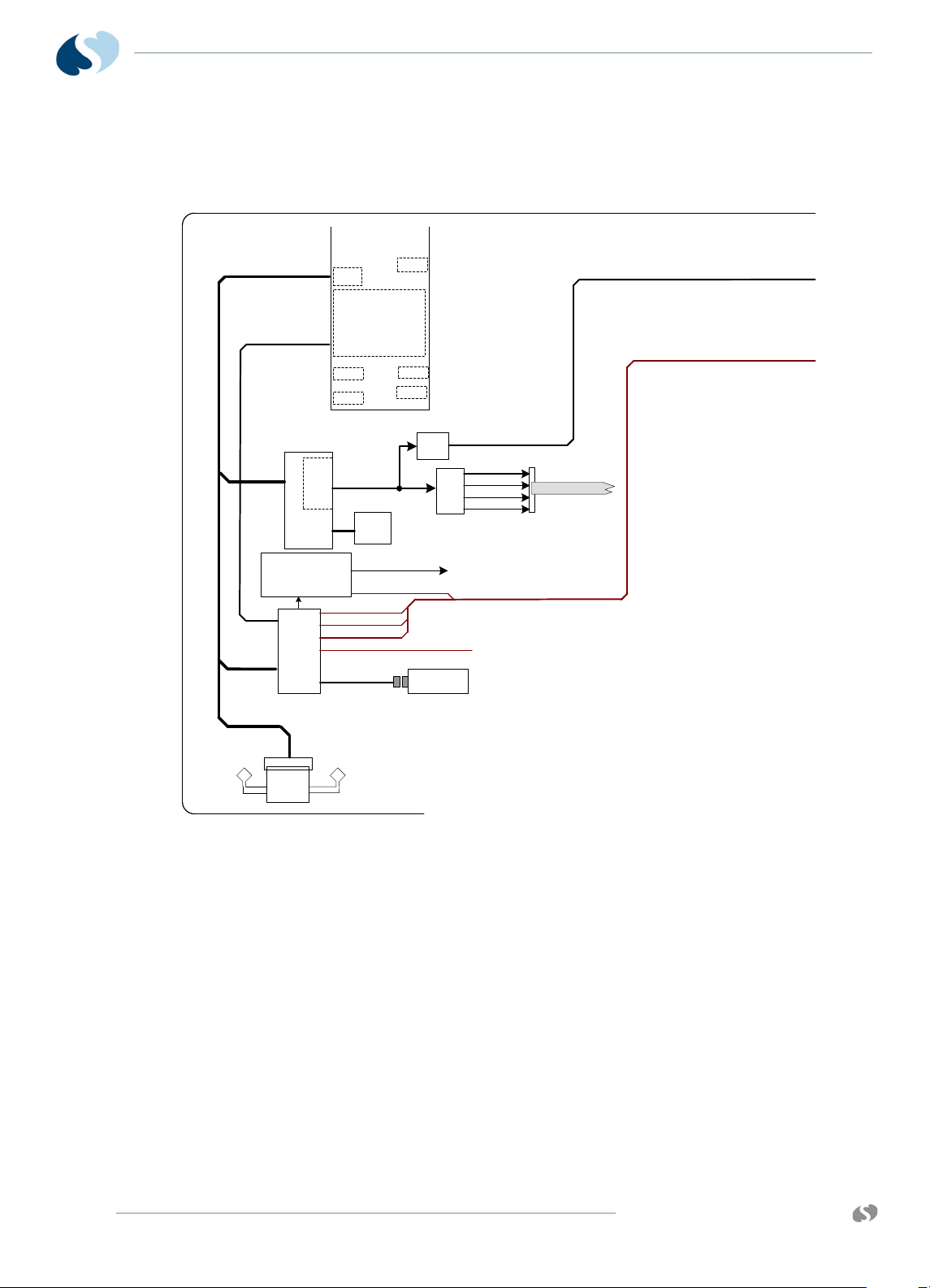
CPU PCB
The CPU PCB combines the CPU core, power supplies, Li-Ion battery
charger, touchscreen interface, USB subsystem, ATI ES1000
graphics processor and all other I/O interfaces (refer to Figure 3-1
on page 3-1). The Freescale MPC8270 running vxWorks Real Time
Operating System (RTOS) interfaces via 64-bit local bus to Flash,
SDRAM, SRAM, and Non-Volatile Memory (NVRAM). The application
code is stored in FLASH and loaded into SDRAM at run time.
NVRAM is used to store monitor configuration data and backed up
by an internal battery in the IC and also provides a real-time clock
function.
www.spacelabshealthcare.com
Figure 3-1 CPU Core Processing
3-1
Page 44
91390
P/O CPU
PCBA
670-1573-xx
SMC1
SCC3
PCI
SMC2
PCI SUBSYSTEM
32-BIT
I2C
I/O
PCI BUS
IEEE
802.11a/b/g
WIRELESS
J641
SPI
MISC I/O
Antenna
Antenna
USB FLASH
DRIVE PCBA
USB Host
Controller
P1
USB 1-2 VBUS
USB (FLASH DRIVE)
USB 2
USB (RECORDER)
USB (TO 7-PORT HUB)
USB 1
MISC I/O
USB POWER
ON/OFF &
OVER- CURRENT SENSE
USB RECODER VBUS
J261
12" TFT LCD DISPLAY
ATI ES1000
GRAPHICS
PROCESSOR
24-BIT DIGITAL
VIDEO OUT
64MB
VIDEO
SDRAM
VIDEO SIGNALS
DVI
TMDS
24-BIT DIGITAL VIDEO
LVDS
EXTERNAL VIDEO (DIGITAL)
PCI BUS
PCI BUS
USB 1-2, USB 1-2 VBUS, USB (TO 7-PORT HUB)
RED SERIAL
BLUE SERIAL
GREEN SERIAL
CONTROL
TO LCD/ BEZZEL ASSY
TO J5 (INTERCONNECT PCBA)
TO J5 (INTERCONNECT PCBA)
TO/FROM
MON-DOCK PCBA
USB 1-2, USB 1-2 VBUS, USB (TO 7-PORT HUB)
EXTERNAL VIDEO (DIGITAL)
P/O CPU
QUBE
T HEORY
A PCI bus is used to communicate to the ATI / ES1000 GPU, USB
host controller, and optional wireless card (refer to Figure 3-2 on
page 3-2).
The USB host controller has 5 USB ports and interfaces to:
• USB port 1 - USB Flash Drive
• USB port 2.3 - becomes external USB1, USB2
• USB port 4 - drives USB Hub on Mon-Dock PCBA
• USB port 5 - drives recorder.
If replacement is ever required, an internal flash drive provides bulk
memory and has special formatting requirements.
An on-board FPGA is used for SDLC Clock generation, and audio
clocks 11.3541 MHz (+/-1%). It is also used for SPI to I2S serial bus
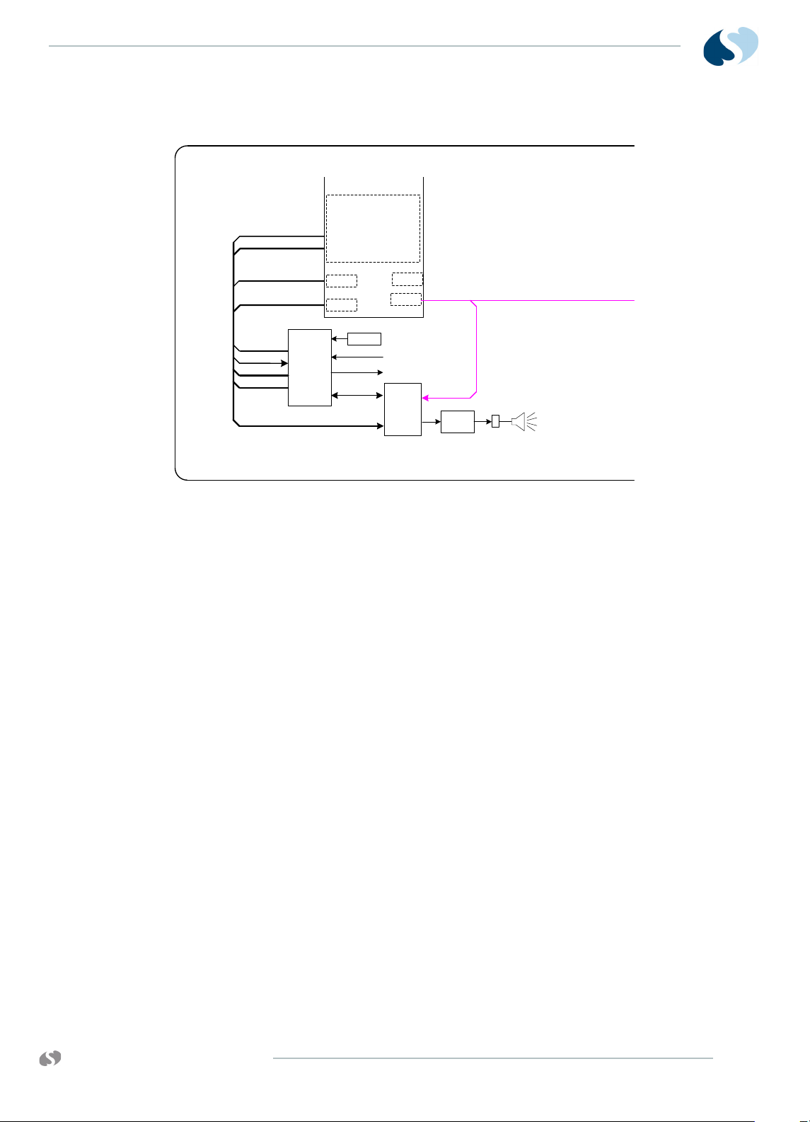
conversion to interface the MPC8270 to the audio codec. The FPGA
is also responsible for decoding the IR remote control signals when
used with the 90360-01 remote control.
Figure 3-2 PCI Subsystem
3-2
www.spacelabshealthcare.com
Page 45
91390 QUBE
P/O CPU
PCBA
670-1573-xx
SMC1
SMC2
I2C
I2C BUS
I/O
RC RX/TX
SPI
MISC I/O
AUDIO
CODEC
AUDIO
AMP
P070
FPGA
PLD
SPI BUS
11.4MHz
Clock
RKEY
CONTROL
I2C BUS
FPGA PGM
RC RX/TX
MISC I/O
MISC I/O
FPGA PGM
SPI BUS
FROM J50
SDLC CLOCK
TO SDLC SECTION OF CPU
MAIN
SPKR
TO/FROM
MON-DOCK PCBA
P/O CPU
T HEORY
Figure 3-3 FPGA Subsystem
www.spacelabshealthcare.com
3-3
Page 46

91390
P/O CPU
PCBA
670-1573-xx
BACKLIGHT
J40
J9
INPUT
SELECT
DC_IN
BATT A
BATT B
3.3VAO
“ALWAYS
ON”
BATTERY
CHARGER
CPU
“ALWAYS ON”
CPU
CONTROL
BAT1_CH_LED
MAINS_LED
PWR_ON_LED
SW_PWR
RKEY
FP LEDs & IR
J50
BAT2_CH_LED
+3.3VAO
FET
SWITCHES
CH_LED2
CH_LED1
+3.3V
DC_IN
+18V BOOST
+5V / +3.3V
BUCK
-12V INVERT
+12V/+12V_REC
BUCK-BOOST
+5V
EN_3V
EN_5V
EN_18V
EN_12V
VCOM
EN_INV
+18V
+3.3V
-12V
+12VREC
+12V
EN_18V
EN_5V
EN_3V
EN_INV
EN_12V
VCOM
FAN
VCOM
FAN_CTL
VCOM
VCOM
VCOM
VCOM
+12V
+3.3VAO
J8
FAN_CTL
BL_PWM
+12V
BL_PWM
+5V
TO LCD/ BEZZEL A SSY
TO FPGA PLD
TO LCD/ BEZZEL A SSY
+3.3VAO
+3.3VAO
DC_IN
DC_IN
PWR_RX_TX
TO
MAIN
CPU
ANY_PWR_IN
TO SYSTEM
FAILURE ALARM
PFAIL
WD_PWR
TO SYSTEM
FAILURE ALARM
TO/FROM
MON-DOCK PCBA
BATTERY BBATTERY A
J9
P401 P402
BATTERY CONNECTOR PCB A
670-1555-xx
WD_PWR
WD_MAIN
SYSTEM FAILURE ALARM
ANY_PWR_IN
FROM MAIN CPU
FROM P.S. “ALWAYS ON” CPU
PIEZOELECTRIC
BUZZER
FET
+5v
REG
ONE-
SHOT
ONE-
SHOT
SUPERCAP
V_ALARM
DUALFREQUENCY
OSCILLATOR
670-1573-03 and later
CPU PCBA only
QUBE
Battery Charger and Power Supply Subsection (on CPU PCB)
T HEORY
3-4
Figure 3-4 Power Supply Subsystem
The Power Supply and Battery Charger subsystem (refer to
Figure 3-4) consists of several subsystems:
• Always On (AO) MCU that provides ON/OFF control
• Battery management / charging control
• Voltage monitoring
• PWM for backlight
• Power sequencing
• Unit shutdown warning (PFAIL)
• Internal temperature monitoring
• Control of +12V, +5V, +3.3V, -12V power supplies
To show and monitor the supply voltages, open the Biomed menu,
click the System Info tab, then select the Analog key. If out of range
conditions are presented, voltages are checked at power-on, and
during run time and events are logged.
www.spacelabshealthcare.com
Page 47

91390 QUBE
T HEORY
The LTC1960 battery charger IC interfaces with the AO MCU. It is
responsible for load switching between AC and battery or batteries,
and direct communication via SMBUS protocol to the Li-Ion smart
batteries. The IC is also responsible for charging the batteries. Refer
to the battery section for more information on batteries.
For 670-1573-03 CPU PCBAs and higher, a high priority technical
alarm has been added. The AO MCU triggers a technical alarm in the
following events:
• Out of tolerance voltages on the +3.3V, +5V, +12V, and -12V
supplies
• No host CPU MPC8270 response
• If the AO MCU also fails to update the watchdog circuit
The technical alarm is a redundant alarming circuit that does not use
the main CPU audio. This circuit can derive power from the external
power supply, battery, or supercap incorporated in the circuit. The
safety circuit sounds if: the unit is unplugged from AC and no
battery is present, or if the unit is operating on battery and the
battery is depleted.
Li-Ion Batteries
If either the charger or host device fails to function correctly,
electronic circuitry is permanently connected within the battery
pack to prevent damage. If an illegal current source is placed across
the battery terminals or an illegal load is connected, the circuitry
also protects the battery. Redundant levels of protection have been
implemented (the primary protection levels are auto-resettable and
the secondary are non-resettable).
If any cell voltage >=4300 µV, the primary protection circuit
prevents the battery from charging. It allows charging again once all
cell voltages are <=4150 µV. If any cell voltage >=4.45 V +/-0.05 V
by blowing a power path logic fuse, the secondary protection circuit
prevents the battery from charging. The fuse is non-resettable,
which renders the battery pack nonfunctional.
The primary protection circuit also provides over-temperature
protection and prevents the battery from charging at temperatures
=>54º C. Then, once the battery temperature has cooled to <=45º C,
it again allows charging.
The primary protection circuit also provides continuous over-current
protection and prevents the battery from charging at Current()
=>4.25 A. Then, once the Average Current() <= 200 µA for 70 sec,
the battery will retest the overcurrent condition, and again allow
charging.
www.spacelabshealthcare.com
The primary protection circuit prevents the battery from being
further discharged once any cell voltage reaches <=2500 µV. Then,
once all cell voltages are >= 3000 µV, it allows discharge again.
3-5
Page 48

91390
QUBE
T HEORY
The primary protection circuit also provides over-temperature
protection and prevents the battery from discharging at
temperatures =>75º C. Then, once the battery temperature has
cooled to <=65º C, it allows discharging again. If the battery reaches
85º C for any reason, the secondary protection circuit blows the
in-line power path logic fuse. The fuse is non-resettable, which
renders the battery pack nonfunctional.
The primary protection circuit also provides continuous over-current
protection and prevents the battery from discharging at Current()
<= -6.25 A. Then, Once the Average Current() >= -200 µA for 70 sec,
the battery will retest the overcurrent condition, and again allow
discharging.
If a short-circuit is placed across the battery + / - terminals, the
primary protection circuit prohibits the discharge of the battery.
When the Average Current >= -1 µA for 70 sec, the battery retests
the short-circuit condition, and again allows discharging. The pack is
designed to withstand reasonable in-rush currents without resetting
the electronics and without interrupting the discharge cycle.
A thermal fuse is fitted in series with the charge/discharge path to
protect the battery from over temperature. This device goes open
circuit if the cell case temperature reaches the fuse's temperature
rating of 93° C (+0° C, -5° C). The fuse cannot be reset, which
renders the battery pack nonfunctional.
A current slow-blow fuse is assembled in series with the battery
pack to protect the battery pack against abusive overcurrent
overload. The hold current is rated at 12 A for 4 hours (minimum @
25C). The fuse is non-resettable, which renders the battery pack
nonfunctional.
Warning:
Make sure that a functional Li-Ion battery SLHC P/N 146-0142-xx is
installed in the unit as part of safety checks. Gas, BISx, and SvO2 modules
do not have battery backup of alarm settings, and alarm settings reset to
defaults if monitor power is interrupted for more than three minutes.
3-6
www.spacelabshealthcare.com
Page 49

91390 QUBE
BACKLIGHT
J40
J9
INPUT
SELECT
DC_IN
V BATT 1
V BATT 2
3.3VAO
“ALWAYS
ON”
BATTERY
CHARGER
CPU
“ALWAYS ON”
MCU
CONTROL
BAT1_CH_LED
MAINS_LED
PWR_ON_LED
SW_PWR
RKEY
FP LEDs & IR
J50
BAT2_CH_LED
+3.3VAO
FET
SWITCHES
CH_LED2
CH_LED1
+3.3V
DC_IN
+5V / +3.3V
BUCK
-12V INVERT
+12V/+12V_REC
BUCK-BOOST
+5V
EN_3V
EN_5V
EN_18V
EN_12V
VCOM
EN_INV
+3.3V
-12V
+12VREC
+12V
EN_5V
EN_3V
EN_INV
EN_12V
VCOM
FAN
FAN_CTL
VCOM
VCOM
VCOM
+12V
+3.3VAO
J8
FAN_CTL
SMART
BATTERY 2
J9
P401 P402
BL_PWM
+12V
BL_PWM
+5V
TO LCD/ BEZZEL A SSY
TO FPGA PLD
TO LCD/ BEZZEL A SSY
+3.3VAO
+3.3VAO
BATTERY CONNECTOR PCBA
670-1658-xx
DC_IN
PWR_RX_TX
TO
MAIN
CPU
ANY_PWR_IN
TO SYSTEM
FAILURE ALARM
PFAIL
WD_PWR
TO SYSTEM
FAILURE ALARM
WD_PWR
WD_MAIN
SYSTEM FAILURE ALARM
ANY_PWR_IN
FROM MAIN CPU
FROM P.S. “ALWAYS ON” CPU
PIEZOELECTRIC
BUZZER
FET
+5v
REG
ONE-
SHOT
ONE-
SHOT
SUPERCAP
V_ALARM
DUALFREQUENCY
OSCILLATOR
670-1573-02 and later
CPU PCBA only
BATTERY
DISCONNECT
SMART
BATTERY 1
BATTERY
1 SENSE
BATTERY
2 SENSE
SW1
TO MUX
TO MUX
ADC
+3.3V
+5V
+12V
DC_IN
VCOM
-12V
BATT 1 SENSE
BATT 2 SENSE
MUX
ADC
SELECT
VCOM
DC_IN
P/O CPU
PCBA
670-1573-xx
DC_IN
TO/FROM
MON-DOCK PCBA
Battery Switch PCBA for Options B and C
T HEORY
Figure 3-5 Battery Switch PCBA for Options B and C
The batteries ship pre-installed for qube options B and C and require
unit disassembly for replacement. The batteries used on these
options are the same type of Li-Ion smart battery used on option A,
but have a lower capacity and are physically shorter. The 670-1658xx battery board used on options B and C includes a small micro
switch mounted on the bottom left of the monitor (refer to
6).
Figure 3-
www.spacelabshealthcare.com
3-7
Page 50

91390
QUBE
T HEORY
Figure 3-6 Battery Switch on Bottom Left of the Monitor
This switch is designed to remove the batteries from the circuit
during shipment and recessed to prevent inadvertent contact from
changing its position. There are a few active components on the
options B and C battery board used to switch the battery V+ lines
and communication line to host with a single switch. These signals
are communicated to the power supply MCU which control battery
charging and front screen icon indications. The battery switch has
symbols to show when to turn the switch on and off. Turn the switch
off for shipping and service (refer to Figure 3-7). Turn the switch to
on for regular operation (refer to Figure 3-8).
Figure 3-7 Battery Switch Off Symbol
3-8
www.spacelabshealthcare.com
Page 51

91390 QUBE
SDLC
J1
J3
USB 1
SW
Y-USB1
X-USB1
DOCKED*
USB 2
SW
Y-USB2
X-USB2
USB 3
SW
Y-USB3
X-USB3
DOCKED*
USB 4
SW
Y-USB4
X-USB4
DOCKED*
DOCKED*
P500
DSB1-5 +PWR
-12V
+3.3V
+5V
+12V
(FROM USB HC) USB (7-PORT HUB)
SW
Y-ETHERNET
X-ETHERNET
DOCKED*
ETHERNET
MONITOR-DOCK PCBA
670-1521-xx
Edge card
X-USB1-4
7-PORT
USB 2.0
HUB
USB 3
USB 4
EXTERNAL NURSE ALERT
(DIGITAL) EXTERNAL VIDEO
DOCKED*
I2C BUS
USB VBUS 1-4
DSB VBUS (PWR) 1-5
DSB 1-5
DSB VBUS 1-5
USB VBUS 3-4
(FROM USB HC) USB 1
(FROM USB HC) USB 2
I2C BUS
USB VBUS 1-2USB VBUS 1-2
SERIAL PORT
DVI VIDEO
SWITCHER
X-EXTERNAL VIDEO (DIGITAL ONLY)
SERIAL PORT
NURSE ALERT
SDLC
DC_IN
DC_IN
-12V
+3.3V
+5V
+12V
+18V
SOFT-START
TO SOFT-START
DC_IN
(FROM P500)
DOCKED*
DC_IN
SERIAL PORT
Y-ETHERNET
NURSE ALERT
-12V
+3.3V
+5V
+12V
Y-EXTERNAL VIDEO (DIGITAL ONLY)
To / From CPU PCBA
INTERFACE PCBA
670-1559-xx
P4
P3
X-ETHERNET
P200
670-1522-xx
-12V
+3.3V
+5V
+12V
J4
P201
P204
DC_IN
SDLC
X-USB1-4 + PWR
DSB1-5 +PWR
EXT NURSE ALERT
P203
ETHERNET
SERIAL
P205
P207
P208
NURSE
ALERT
USB-1
USB-2
USB-3
P202
USB-4
SERIAL PORT
SDLC
(FLEXPORT)
P206
+5V +12V
X-EXTERNAL VIDEO (DIGITAL ONLY)
CONNECTOR PCBA
DOCKING STATION PCBA
P500
670-1558-xx
(DIGITAL ONLY)
P501
P502
DC_IN
EXTERNAL
POWER SUPPLY
+20VDC
DVI DIGITAL
VIDEO OUT
Y-EXTERNAL VIDEO
SERIAL
FLEXPORT
SDLC
+5V +12V
SERIAL PORT
SDLC
ETHERNET
NURSE ALERT
Y-USB1-4
USB-1
USB-2
USB-3
USB-4
NURSE ALERT
P508
P503
P506
P505
P507
P504
Y-ETHERNET
-12V
+3.3V
+5V
+12V
DOCKED*
J70
DOCKED LED
EXTERNAL
POWER SUPPLY
+20VDC
DVI DIGITAL
VIDEO OUT
DSB Support removed from
670-1521-02 and above PCBAs
I/O PORT
EXPANSION
DSB POWER
CONTROL
USB POWER
CONTROL
DSB 1
DSB 2
DSB 3
DSB 4
DSB 5
DSB Support removed from
670-1522-02 and above PCBAs
T HEORY
Figure 3-8 Battery Switch On Symbol
Monitor Docking PCBA and Connector PCBA
www.spacelabshealthcare.com
The monitor docking PCB has a docking connector for interface to a
docking station (refer to Figure 3-9). All I/O connectors and power
are routed on this board. They are available to either the docking
station when docked, or presented at the rear of the monitor when
not docked. High-speed signals like Ethernet, DVI and USB are
switched so the unused stubs when docked do not affect the signal
impedance.
Figure 3-9 Monitor Docking PCBA and Connector PCBA
3-9
Page 52

91390
QUBE
Input power from the external power supply is routed through this
board for both the monitor and docking station inputs. It also runs
through a soft start circuit to limit in-rush current. A 7-port USB Hub
is found on the docking station board to expand out USB / DSB.
The connector board is a board with all the I/O connectors on it. All
the I/O signals from the monitor dock PCBA are routed to the
connector board using a small interconnect PCB rather than cables.
This increases robustness and ease of service.
Front Bezel Assembly
T HEORY
3-10
Figure 3-10 LCD Display Assembly for Option A
Note:
Options B and C do not have the IR Receiver. Option C does not
have the internal nurse alert,
The front bezel assembly contains:
www.spacelabshealthcare.com
Page 53

91390 QUBE
J5
SDLC
+12V
+5V
-12V
+12VR
J7
P600
J
5
PATIENT
MODULE
J6
SDLC
SDLC
SDLC
USB (RECORDER)
+12VR
OEM
RECORDER
119-0549-xx
J6
+12V
+5V
-12V
+12VR
+5V
+12V
-12V
+5V
+12V
-12V
USB RECORDER VBUS
USB (RECORDER)
USB RECORDER VBUS
CAPNO POD
J7
P300
SDLC
+5V
+12V
-12V
INTERCONNECT PCBA
670-1481-xx
FLEXPACK PCBA
670-1551-xx
Pod Interface PCB
T HEORY
• 5-wire resistive touch panel
•LCD display
• Backlit ON/OFF button
• Integrated alarm light
• Battery status / AC connected LED’sand the IR remote keypad
receiver. The screen is wrapped in an aluminum frame and
powder coated for increased strength. The presentation of alarm
lights through the touch panel is patent pending.
All battery status and AC connected status comes from the CPU
PCB. The state of alarms to enable red, yellow, or cyan alarm lights
for high, medium, and low priority alarms also come from the CPU
PCB. The ON/OFF switch state is de-bounced by the AO MCU and
state updated to the system.
Note:
Option C does not have a pod port.
The pod interface PCB has gold immersion plated pads for corrosion
resistant contacts for electrical connection to an optional
Capnography Pod. A cable connects the SDLC and power for the
pod to the interconnect PCB. Ball stud contacts in the pod provide
more grounding and help secure the pod to the monitor.
Interconnect PCB
www.spacelabshealthcare.com
The interconnect PCB routes SDLC and module or pod power from
the CPU to the module bay and pod interface PCB. It also provides a
connection point for the optional USB thermal printer. The thermal
printer gets power from the 12-V supply and has a separate current
limiting circuit split off from the 12-V supply. The recorder talks to
the host CPU using USB protocol.
Figure 3-11 Connector PCBA
3-11
Page 54

91390
QUBE
T HEORY
3-12
www.spacelabshealthcare.com
Page 55

91390 QUBE
Maintenance
Overview
The following information describes the requirements and tests
necessary for safety and performance verification of the monitor.
Caution:
Observe precautions for handling electrostatic-sensitive devices!
Notes:
• Never touch electrostatic-sensitive electronic components
without following proper anti-static procedures, including the
use of an ESD wrist band and mat. An electrostatic discharge
from your fingers can permanently damage electronic
components and cause latent failures.
• All static-sensitive electronic components are packaged in
static-shielding bags. Keep the bag in case you must
repackage the component to store it or return it to Spacelabs
Healthcare for any reason.
• Perform cleaning, preventive maintenance, and safety checks
annually and following any product disassembly or assembly.
Only trained personnel only should perform preventive
maintenance and safety checks.
www.spacelabshealthcare.com
4-1
Page 56

91390
QUBE
Required Test Equipment
• Electrical Safety Analyzer — Dynatech Nevada 232C or
equivalent
• Patient Simulator — Dynatech Nevada 300B or equivalent
Notes:
• Before you test, make sure that the module housing or
housings and its DC power supply or supplies have their
associated cables attached, but are not interconnected.
• Make sure that the Ethernet cable and AC power sources are
removed.
• The AC line is auto detected; no user selection is necessary.
• Ensure that the leakage test equipment is calibrated.
Mechanical Inspection
Make sure that:
M AINTENANCE
• The monitor and all optional equipment are clean.
• All screws are tight.
• The case and connector pins are not damaged.
• There are no frayed or pinched wires or cables.
Tests for Electrical Safety
To protect the patient from electrical shock, especially micro-shock,
do the required safety tests. It has been determined experimentally
that current values in the microampere (mA) range can cause fatal
arrhythmias in electrically susceptible patients. A patient is deemed
electrically susceptible when connected to monitoring equipment.
Definitions
Classification — IEC/EN/UL 60601-1 Safety standard designation for
the class of equipment and type of patient applied parts that
indicate the degree of protection provided against electrical shock.
Leakage Current — Current that is not functional. It includes patient
leakage, ground leakage, and enclosure (or chassis) leakage.
Patient Lead Leakage — Current that flows from the applied part of
the patient lead to ground.
4-2
Chassis Leakage — Current flowing from the enclosure (or from
conductive parts accessible to the operator) through the ground
conductor.
www.spacelabshealthcare.com
Page 57
91390 QUBE
M AINTENANCE
Normal Condition — Condition in which all means provided for
protection are intact. Includes, ground connections, insulation,
creepage, and clearance distances.
Single Fault Condition — Open ground, open neutral, line voltage on
a patient connection, or any single state other than normal condition
that could compromise patient safety.
UUT — Unit Under Test.
Spacelabs Healthcare does not endorse standards to the exclusion
of others. Therefore: BE SURE TO CHECK YOUR LOCAL
REQUIREMENTS TO MAKE SURE YOUR EQUIPMENT SAFETY
TESTS COMPLY WITH LOCAL STANDARDS. Generally accepted
standards for medical monitoring equipment, such as the
Underwriters Laboratory (UL) and the National Fire Protection
Association (NFPA) standards, are summarized in Table 4-1 on page
4-3.
Table 4-1 Summary of Standards for Medical Monitoring Equipment
International Mains to
Chassis Leakage
100 μA - normal condition, ground
attached (AC connector to chassis)
500 μA - single fault condition, open
ground, or reverse polarity
* Measured from the AC Power cord third wire ground to the most distant ground attachment
Equipment Required
Warning:
Before you start safety tests, ensure that no patient is connected to the
device under test. If safety tests must be performed on equipment
currently monitoring a patient, obtain permission to disconnect the
cables from the monitor and patient.
U.S. (120 V) Mains to
Chassis Leakage
300 μA - normal condition, ground
attached (AC connector to chassis)
300 μA - single fault condition, open
ground, or reverse polarity
Mains Resistance
500 milliohms*
500 milliohms*
Electrical Safety Analyzer, Fluke model 232D, or equivalent.
Perform these tests according to the scheduling requirements for
the hospital, at least annually or after repair or modification.
Note:
Perform all tests according to the operations manual for the
safety analyzer and any local requirements.
Ground Resistance
www.spacelabshealthcare.com
1 Attach the power cord to the monitor under test.
2 Measure the resistance from the AC power cord third wire ground
to a chassis location, such as the equipotential post on the rear of
the monitor.
4-3
Page 58

91390
QUBE
3 Check that the resistance is less than 500 milliohms (0.5 ohms).
Chassis Leakage Current Tests
1 Plug the leakage analyzers into mains power.
2 Plug the equipment into the AC receptacle on the analyzer.
3 Verify that the leakage current from the chassis to ground is less
than the values in Table 4-2 on page 4-4.
Table 4-2 Enclosure Leakage Test Conditions and Limits
M AINTENANCE
Neutral
Condition
Closed neutral Closed ground Normal polarity 100 μA300μA
Open neutral Open ground Normal polarity 500 μA300μA
Closed neutral Open ground Normal polarity 500 μA300μA
Ground
Condition
Polarity
International
Limit
U.S. Limit
Patient Lead Leakage Current Tests (Patient Modules)
For patient lead leakage test instructions, refer to the service manual
of the specific module or modules you use.
Preventive Maintenance
A Spacelabs Healthcare Field Service Engineer or qualified hospital
biomedical technician checks the monitor and optional equipment
for acceptable performance and electrical safety. Checks are done
to make sure that the monitor and option equipment operate
according to current requirements.
Touchscreen Calibration
4-4
In the event the touchscreen becomes difficult to use or a
replacement has been installed, calibrate it. Calibrate by using the
calibration function in the Biomed menu.
To perform touchscreen calibration
1 Attach a mouse.
2 Power ON the monitor and wait for the monitor to pass the self
tests.
3 Click (or touch) the Monitor Setup key.
4 Click (or touch) the Privileged Access key.
5 Enter the Biomed password (default is biomed).
6 Click (touch) Biomed Setup.
7 Click (touch) Touchscreen Calibration.
www.spacelabshealthcare.com
Page 59

91390 QUBE
Functional Tests
Monitor Self-Test
M AINTENANCE
8 Wait for the Reset Monitor dialog box to display.
9 Click (touch) the Reset Monitor key.
The monitor resets. After 15 to 20 seconds, a lighted box will
appear in the upper left corner of the screen.
10 Touch the lighted box for one or two seconds until it
disappears.
Three more lighted boxes appear, one at a time, in the upper
right, lower right, and lower left corners.
11 Touch the lighted boxes as they appear.
After you touch these four corners one at a time as the boxes
appear, the touchscreen is calibrated.
A power-ON self-test is performed each time the monitor is turned
ON.
• The power ON/OFF switch illuminates indicating +5 V is present.
• If the monitor operates on external AC power, the power LED on
the front bezel also illuminates.
• If the monitor operates on AC power and batteries are charging,
the battery A and battery B status LEDs on the front bezel flash
ON and OFF at a constant rate. Once batteries fully charge,
these LEDs remain ON. If no battery is present, one or both of
the battery status LEDs remain OFF.
Monitor Functional Tests
This procedure verifies operation of the recorder assembly, network
connectivity, alarm relay output, and external SDLC connections. It
assumes that a 91496-B or 91496-C multi-parameter module (ECG,
RESP, and two PRESS channels) is available for testing purposes. If
these parameters are not available, you can substitute similar
modules.
Verification of Monitor Functions
Note:
To begin the test, make sure that no modules are inserted and no
Flexports or other SDLC devices are connected.
www.spacelabshealthcare.com
1 Plug in the monitor and verify that the front bezel power LED is
lit. If one or two batteries are installed, verify that the appropriate
battery LED or LEDs are ON solid or flashing.
2 To power ON the monitor, press the power ON/OFF switch.
3 Verify the following sequence of events:
a The power ON/OFF switch illuminates.
4-5
Page 60

91390
QUBE
M AINTENANCE
b The embedded front and rear alarm light LEDs illuminate
briefly. Verify that all LEDs are functional.
c The Diagnostic menu displays. (If errors are noted during
power ON, contact your Spacelabs Healthcare Field Service
Engineer.)
d If batteries are installed, the fan begins operating within
60 seconds after turning ON the monitor. The fan turns OFF
unless the internal temperature requires more cooling by the
fan.
e Monitor keys display along the right side of the screen.
4 Insert the ECG module without a patient cable connected. Verify
that the ECG parameter key appears on the screen with ??? and
the message LEADS OFF.
5 Connect a patient simulator to the ECG input with a patient cable.
Set the simulator to a known rate.
6 Verify that the ECG count and the lead being monitored are
displayed to the right of the ECG parameter key.
7 Verify that the ECG waveform appears on the screen.
8 Connect a patient simulator to the invasive pressure inputs.
9 Zero the pressures and verify that the numerics and waveforms
are accurate.
Optional Recorder Assembly for Options A and B
If the monitor is configured with the optional recorder assembly,
verify that the monitor initiates a recording. To verify that the
monitor initiates a recording, touch the RECORD key then touch one
of the flashing parameter keys.
Note:
The printed waveform should not have defects such as gaps,
extra lines, etc. If there are defects, notify a Spacelabs Healthcare
Field Service Engineer for servicing, or replace the recorder.
External Alarm Relay Output for Option A
If the monitor is configured to use the alarm relay output, to
interface to an external alarm device:
1 Plug the cable into the external alarm connector.
2 Initiate a high-priority alarm.
3 Verify that the external alarm responds appropriately.
4-6
4 If an external alarm light capable of displaying multiple colors is
attached, turn the high-priority alarm OFF. Generate a mediumpriority alarm.
5 Verify that the external alarm responds appropriately.
6 Repeat steps 4 to 5 for a low-priority alarm.
www.spacelabshealthcare.com
Page 61

91390 QUBE
An alternate method is to connect the cable and turn the monitor
ON and then OFF. Each color of the embedded alarm light
momentarily illuminates. An external alarm light also briefly
illuminates.
Ethernet (Wired)
1 Attach a 10/100BaseT cable from an active network onto the rear
panel connector.
2 Verify that the green link light on the connector is ON.
Assembly/Disassembly Procedures
Caution:
Before you begin any disassembly procedures, power OFF the monitor,
disconnect the AC cord from the AC power receptacle, and remove the
batteries.
M AINTENANCE
Note:
The external power supply is not designed for disassembly.
Required Tools and Parts
• Anti-static mat with wrist strap
• #1 and #2 Phillips-head screwdriver
• 3/16-inch nut driver
• Tool, antenna extraction, wireless card, P/N 003-0286-00
• XPREZZON™ and qube™ System Administration Manual, P/N
070-2380-xx
Setup for Disassembly
The battery switch has symbols to show when to turn the switch on
and off. Turn the switch off for shipping and service (refer to
Figure 4-1). Turn the switch to on for regular operation (refer to
Figure 4-2).
www.spacelabshealthcare.com
Figure 4-1 Battery Switch Off Symbol
4-7
Page 62

91390
QUBE
M AINTENANCE
Figure 4-2 Battery Switch On Symbol
For Option A
1 Remove the external power supply cable and battery or batteries,
if present.
2 Remove the patient parameter module.
For Options B and C
1 Remove the external power supply cable and turn the battery
switch to off.
2 Remove the patient parameter module.
Remove the Bezel Assembly
1 Place the monitor face-down on a stable and padded surface.
2 Remove the eight finishing plugs from the rear enclosure as
shown in Figure 4-3 for option A.
3 Remove the 10 screws from the rear enclosure, as shown in
Figure 4-3.
4-8
www.spacelabshealthcare.com
Page 63

91390 QUBE
M AINTENANCE
Figure 4-3 Screw Locations on Option A
4 Place the monitor on its feet and separate the bezel assembly
from the rear enclosure, as shown in Figure 4-4 on page 4-10.
www.spacelabshealthcare.com
4-9
Page 64

91390
175-1855-xx Com4 to J941 (CPU)
Touch Screen
Flat Ribbon Cable - P341 (CPU)
Center Video Port
175-1858-xx - J40 (CPU)
Center Video
Port - J40
(CPU)
175-1857-xx Com1 to J50 (CPU)
175-1857-xx Com1 to
J50 (CPU)
175-1856-xx to J261 (CPU)
QUBE
M AINTENANCE
Reassembly
Caution:
Figure 4-4 Bezel Assembly and Rear Enclosure
5 Start from the bottom and disconnect the three black wire
bundles from the monitor side. Refer to Figure 4-4.
6 Remove the video cable P/N 175-1856-00 from the monitor.
7 Disconnect the remaining black ribbon cable from the monitor
side. Refer to Figure 4-4.
8 Remove bezel assembly.
Use caution when handling the cables. The cables are fragile and can
easily be damaged.
1 Position the new bezel assembly as shown in Figure 4-4.
2 Connect cable 175-1855-xx Com4 to J941 (CPU).
3 Connect cable Center Video Port 175-1858-xx to J40 (CPU).
4 Connect cable 175-1856-xx to J261 (CPU).
5 Connect cable 175-1857-xx Com1 to J50 (CPU).
4-10
www.spacelabshealthcare.com
Page 65

91390 QUBE
M AINTENANCE
Figure 4-5 Connect the cables
6 To attach the bezel assembly to the rear enclosure with the 10
original screws. Be careful not to over-tighten the screws.
CPU PCB
Note:
The bezel and rear enclosure must align on the bottom of the
monitor. The bottom edge of the enclosure must fit into the
bezel. Be careful not to pinch any cables, especially the touch
screen cable.
7 Install the eight finishing plugs removed in Step 2 on page 4-8.
8 Perform the functional test procedure. Refer to Monitor
Functional Tests on page 4-5.
1 Perform Step 1 on page 4-8 though Step 8 on page 4-10.
Notes:
• If the wireless option is not installed, skip to Step 6 on page 4-
12.
• The replacement CPU PCB does not come with a new wireless
adaptor PCB. Remove the wireless adaptor card and install it
on the new CPU PCB.
2 To remove the two antenna cables from the wireless card, use the
003-0286-00 antenna extraction tool as shown in Figure 4-6.
Caution:
www.spacelabshealthcare.com
Use caution when handling the two antenna cables. The cables are fragile
and can easily be damaged.
4-11
Page 66

91390
Adaptor Clips
Do not
remove USB
daughter
board screw
Fan Cable
QUBE
M AINTENANCE
Figure 4-6 Wireless Antenna Cables
3 Gently press outward on the retaining clips that hold the wireless
adaptor card in place. Remove the wireless adaptor board.
4 Set aside the wireless adaptor PCB for installation on the
replacement CPU PCB. Use proper ESD protection.
5 Disconnect the fan cable from the CPU PCB.
6 Remove the 12 screws that secure the CPU PCB to the chassis.
Notes:
• Do not remove the screw that secures the USB daughter
board to the CPU PCB. Refer to Figure 4-6.
• The CPU PCB is press fitted onto the connectors, for the
interface, monitor dock, and battery PCBs.
7 Remove the old CPU PCB. Gently pull the CPU away from the
interface, monitor dock, and battery PCB connectors.
8 Disconnect the speaker cable from the back-side of the CPU PCB.
9 To replace the USB card, remove the screw that attaches the old
USB to the CPU PCB. Install the new USB card. Refer to Figure 4-
7 on page 4-13.
Notes:
• If you replace the USB daughter card, format and configure it.
Refer to the XPREZZON and qube System Administration
Manual (P/N 070-2380-xx).
4-12
www.spacelabshealthcare.com
Page 67

91390 QUBE
USB Card
M AINTENANCE
• The CPU PCBA contains a USB flash drive PCBA that stores
user-created Custom Trends, as well as Citrix certificates
required for the DNA feature.
• Reformat the new USB flash drive as part of the CPU
replacement procedure.
• When you replace the CPU PCBA, Spacelabs Healthcare
recommends that you transfer the old USB flash drive to the
new CPU PCBA.
Figure 4-7 USB Flash Drive
10 Connect speaker cable to P070 port. Connect the fan cable to J8
Port.
11 Install the new CPU onto the chassis. Connect to the battery,
monitor dock, and interface PCBs.
12 Make sure that the speaker and fan cables are not pinched.
13 Use the 12 screws removed in Step 6 on page 4-12 to secure the
CPU to the main chassis.
14 Reinstall the wireless adaptor PCB. Reconnect the two antenna
cables if applicable.
15 Place the monitor upright, as shown in Figure 4-4 on page 4-10.
16 Position the bezel assembly as shown in Figure 4-4 on page 4-10.
17 Connect cable 175-1855-xx Com4 to J941 (CPU).
18 Connect cable Center Video Port 175-1858-xx to J40 (CPU).
19 Connect cable 175-1856-xx to J261 (CPU).
20 Connect cable 175-1857-xx Com1 to J50 (CPU).
21 Move the bezel into position. Place the monitor face-down on a
stable, padded surface. To attach the bezel assembly to the rear
enclosure again, use the original screws and finishing plugs
(Refer to Step 2 on page 4-8 and Step 3 on page 4-8).
www.spacelabshealthcare.com
Note:
Options B and C do not have finishing plugs.
4-13
Page 68

91390
QUBE
22 Make sure that the rear enclosure aligns with the bezel (bottom
of monitor).
Restore Data to the Monitor
The CPU PCBA contains a USB flash drive PCBA that stores usercreated Custom Trends, as well as Citrix certificates required for the
DNA feature. These procedures outline the steps for successful
restoration of this data to your monitor when replacing the CPU
Flash Drive PCBA.
1 Remove and replace the CPU as specified in CPU PCB on
page 4-11.
2 Complete replacement of the CPU PCBA transfers a
nonformatted and nonprogrammed USB drive PCBA into the
qube monitor. Refer to Figure 4-7 on page 4-13 to identify the
location of the USB drive.
Select Option 1: Exchange the USB Drive PCBAs or Option 2: Format
the USB Drive as the next step. Use Option 1 if the USB Flash Drive
PCBA currently functions with no errors.
M AINTENANCE
Option 1: Exchange the USB Drive PCBAs
To maintain the user-created customized trends and Citrix
certificates in the USB drive, exchange the USB drives between the
defective CPU PCBA and the new CPU PCBA.
1 Locate the USB Drive is on the back side of the CPU PCBA. Refer
to Figure 4-7 on page 4-13 for the location of the USB Drive.
2 Remove the screw holding the USB drive to the CPU board.
3 Lift the USB drive PCBA away from the defective CPU PCBA.
4 Remove the USB drive PCBA from the replacement CPU PCBA.
5 Exchange the USB drives between the two CPU PCBAs.
6 Reassemble the monitor as described in Assembly/Disassembly
Procedures on page 4-7.
Option 2: Format the USB Drive
The factory does not format the USB flash drive that is on the
replacement CPU PCBA. A built-in software utility in the extended
diagnostics menu in the monitor formats the USB drive. If the
software utility in the monitor does not format the USB drive, the
message: System Software failure. Review error log for further
details shows after the power-ON self tests complete.
4-14
Note:
If you receive this message, format the new USB drive and
manually reprogram the user-defined Trends and DNA (Citrix)
certificates.
www.spacelabshealthcare.com
Page 69

91390 QUBE
M AINTENANCE
1 After you install the new CPU PCBA into the chassis, reassemble
the monitor as described in Assembly/Disassembly Procedures
on page 4-7.
2 Connect the power supply to the 91390 monitor.
3 To format the USB drive, power-ON the monitor (cold-boot).
4 To enter extended diagnostics, touch the lower corners of the
touchscreen in sequence during the 4-3-2-1 countdown. Touch
the corners of the visible part of the lighted electronic display
(LED), not the corners of the bezel (refer to Figure 4-8 on page 4-
15). If you use a mouse, click both the right and left mouse buttons
simultaneously during the countdown. The Main Diagnostics
Menu is shown in Figure 4-9.
Figure 4-8 Touch Points to Enter Extended Diagnostics on Options A
and B (left) and Option C (right)
5 Touch or click the f - format USB file system key.
www.spacelabshealthcare.com
4-15
Page 70

91390
QUBE
M AINTENANCE
Figure 4-9 Main Diagnostics Menu
The process takes about 10 seconds to complete. The results are
shown in Figure 4-10 on page 4-16.
Figure 4-10 Format USB Drive Results Screen
6 To cold-boot the monitor, touch or click the D - run diagnostics,
then the R - Reset Monitor (cold boot) keys. Let the monitor to
fully boot.
4-16
7 To restore the faculty user-defined rends and DNA (Citrix)
certificates, refer to the XPREZZON and qube Bedside Monitoring
Operations Manual (P/N 070-2112-xx).
8 Perform the retest procedure. Refer to Functional Tests on
page 4-5.
www.spacelabshealthcare.com
Page 71

91390 QUBE
Complete Main Chassis Removal
1 Remove the bezel by performing Step 1 on page 4-8 though Step
8 on page 4-10.
2 To remove the two antenna cables from the wireless card, if
present, use the 003-0286-00 Antenna extraction tool as shown
in Figure 4-11.
3 For option A, remove the four chassis screws, and the two hidden
screws seen in Figure 4-11 on page 4-17. For options B and C,
remove the two chassis screws and the one hidden screw.
Note:
When you work on chassis components, first remove the CPU
PCBA.
M AINTENANCE
Figure 4-11 Complete Main Chassis Removal
4 Place the monitor on its rear panel. Remove the five screws on the
bottom of the monitor, as shown in Figure 4-11.
5 Place the monitor upright.
6 Remove the connector PCB standoffs. Refer to Figure 4-12 on
page 4-18.
www.spacelabshealthcare.com
4-17
Page 72

91390
PCB Standoffs
QUBE
M AINTENANCE
Reinstall the Chassis
Figure 4-12 PCB Standoffs
7 Open module bay door to access and disconnect the 175-1860-xx
Pod interface cable from the Pod Interface Board for options A or
B.
8 Remove the DSB and docking connector covers as shown in
Figure 4-26 on page 4-30 for option C.
9 Remove the printer, if present in options A or B.
10 With the module bay door open, pull the main chassis from the
rear enclosure.
Note:
The DSB connector must clear the rear enclosure. To allow the
DSB connector to clear, gently flex the rear enclosure.
1 With the module bay door open, slide the chassis assembly into
the rear enclosure for options A or B.
2 Attach the 175-1860-xx Pod interface cable to the Pod Interface
Board again.
3 Install the four chassis screws again for option A. Install the three
chassis screws again for options B or C.
4-18
www.spacelabshealthcare.com
Page 73

91390 QUBE
SDLC Interface PCB
M AINTENANCE
Note:
For option A, install the hidden screw on the lower-right side of
the chassis through printer slot and hold the screw in place.
4 Install the connector PCB Standoffs again.
5 Place the monitor on its rear. Reinstall the five screws on the
bottom of the monitor.
6 Install the wireless card again, if applicable.
7 Attach antenna cables to the wireless card again, if applicable
8 Install the bezel again. Refer to Step Step 15 on page 4-13 through
Step 22 on page 4-14.
9 Perform the retest procedure. Refer to Functional Tests on
page 4-5.
1 Remove the Bezel Assembly by perform Step 1 on page 4-8
though Step 7 on page 4-10.
2 Perform Step 2 on page 4-15 through Step 7 on page 4-18 to
remove the Main Chassis assembly.
3 Remove the CPU. Refer to CPU PCB on page 4-11
4 Remove the two screws shown in Figure 4-13 on page 4-19.
www.spacelabshealthcare.com
Figure 4-13 SDLC Interface
4-19
Page 74
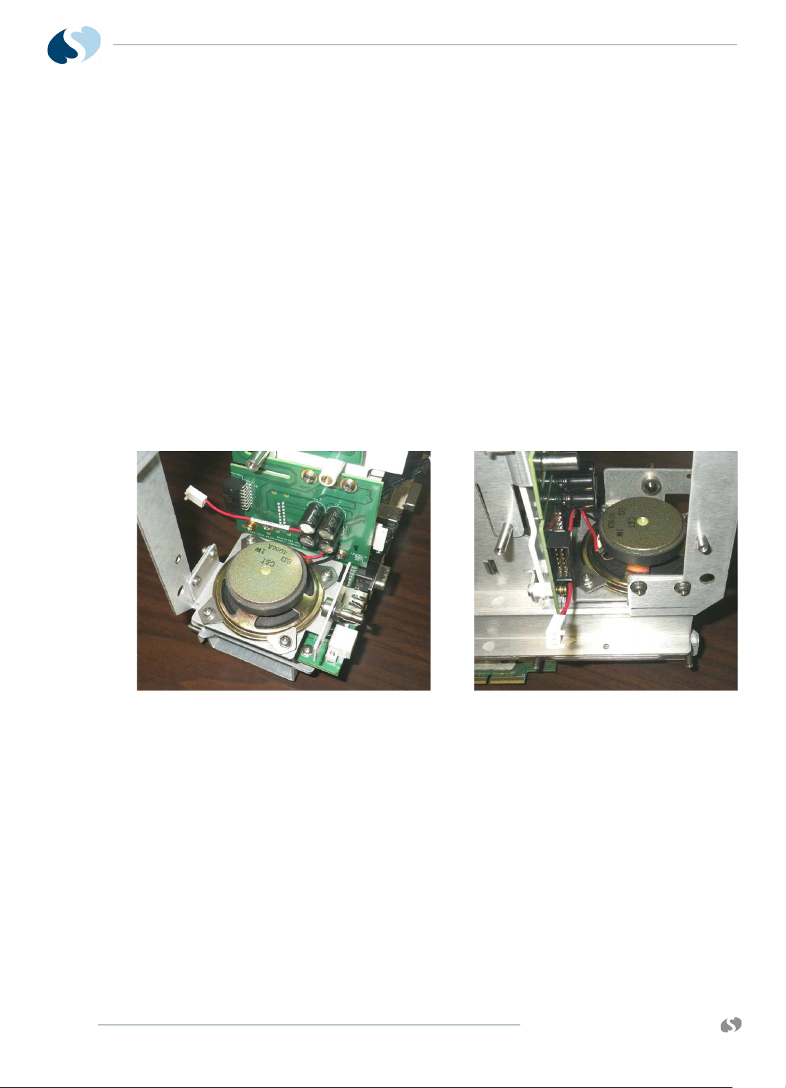
91390
Speaker
QUBE
M AINTENANCE
5 Remove the two screws from the SDLC Interconnect as shown in
Figure 4-13.
6 Install the Interface PCB and mounting bracket in the chassis with
the two screws.
7 Reinstall the CPU. Refer to Step 10 on page 4-13 through Step 14
on page 4-13
8 Slide the complete chassis assembly into the rear enclosure. Refer
to Figure 9.
9 Reinstall the chassis. Refer to Reinstall the Chassis on page 4-18.
1 Perform Step 1 on page 4-18 through Step 9 on page 4-19 to
access the Main Chassis assembly.
2 Disconnect the speaker connector from the CPU PCB.
3 Remove the four mounting tabs that secure the speaker to the
speaker bracket as shown in Figure 4-14 on page 4-20.
4-20
Figure 4-14 Speaker and Speaker Bracket
4 Remove the old speaker. Attach the new speaker onto the
speaker bracket using the four mounting tabs as shown Figure 4-
14.
5 Attach the speaker cable to the CPU Board.
6 Reinstall the main chassis into the rear enclosure. Attach the
bezel to the rear enclosure. Refer to Reinstall the Chassis on
page 4-18.
www.spacelabshealthcare.com
Page 75

91390 QUBE
Screws
Mon-Dock PCB
M AINTENANCE
1 Perform Step 1 on page 4-18 through Step 9 on page 4-19 to
access the Main Chassis assembly.
2 With the Chassis assembly face down, remove the seven screws
shown in Figure 4-15 on page 4-21 for option A. Remove the five
screws for option B or C.
www.spacelabshealthcare.com
Figure 4-15 Docking PCB
3 Replace the old PCB. Attach it again to the bottom of the chassis
assembly with the original screws.
4 Perform the retest procedure. Refer to Functional Tests on
page 4-5.
4-21
Page 76

91390
Rod
E-clip
Spring
QUBE
Battery Door for Option A
1 Open the battery door.
M AINTENANCE
Figure 4-16 Battery Door
2 Remove E-clip. Refer to Figure 4-16.
3 Slide the rod down through the door and rear enclosure. Refer to
Figure 4-16.
4 Remove the old door assembly.
5 Install the new door assembly.
6 Make sure that the spring is positioned correctly. Refer to
Figure 4-17.
Figure 4-17 Battery Door Spring
7 Slide the rod through the rear enclosure and door.
4-22
8 Attach E-clip.
www.spacelabshealthcare.com
Page 77

91390 QUBE
Remove
Loosen
Connector Board
Remove
Interface PCBA
Connector Board PCB
2 Remove the three screws, shown in Figure 4-18 for option A.
M AINTENANCE
1 Perform Step 1 on page 4-18 through Step 9 on page 4-19 to
access the Main Chassis assembly.
Remove the two screws for options B or C.
Note:
3 Remove the Connector Board.
4 Install the new Connector Board making sure that the connection
Note:
5 Connect board to the Interface PCBA. Connect to Monitor and
6 Install the three screws removed in step 2 for option A. Install the
Figure 4-18 Connector Board PCB
Loosen the top three Monitor Dock PCB screws.
to the interface PCB is good.
Tighten the top three Monitor Dock PCB screws.
Dock boards.
two screws removed in step 2 for options B or C.
www.spacelabshealthcare.com
4-23
Page 78

91390
QUBE
Replace the Battery Contact PCB
1 Remove the chassis. Refer to Complete Main Chassis Removal on
page 4-17.
2 Remove the connector PCB.
M AINTENANCE
Figure 4-19 Replace the Battery PCBA
3 Remove the three screws holding the battery PCB to the chassis.
4 Disconnect the battery PCB from the CPU.
5 Replace the battery connect PCB.
6 Reinstall the connector PCB.
7 Reinstall the chassis and bezel assembly.
8 Install the battery. Disconnect the AC mains. Make sure the unit
powers ON.
9 Perform the retest procedure. Refer to Functional Tests on
page 4-5.
4-24
www.spacelabshealthcare.com
Page 79
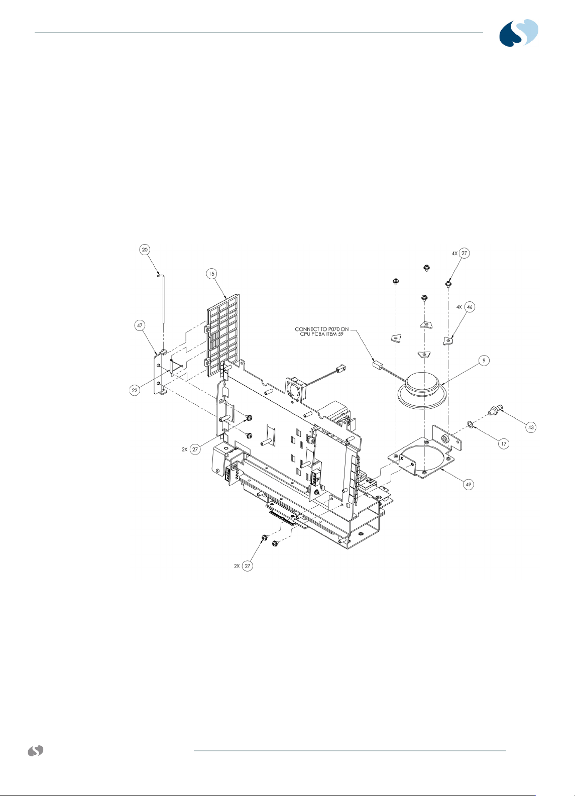
91390 QUBE
Replace and Align the Module Door
1 Remove the chassis. Refer to Complete Main Chassis Removal on
page 4-17.
2 To remove the door, remove the two screws fastening the hinge
to the wall of the module compartment assembly. This frees the
door assembly. When you install a new door, do not tighten the
two screws until you completely secure the chassis assembly to
the rear housing.
3 After the chassis and rear housing are reassembled, position the
door so that it freely opens and closes, and then tighten the two
screws.
M AINTENANCE
www.spacelabshealthcare.com
Figure 4-20 Module Door
4-25
Page 80

91390
Handle
QUBE
M AINTENANCE
1 Separate the bezel from the rear enclosure. Refer to Remove the
Bezel Assembly on page 4-8.
2 Remove the four screws on the handle cover as shown here
Figure 4-21 on page 4-26.
Figure 4-21 Handle
3 Remove the handle and dampening rod from the rear enclosure.
Reinstall the Rear Handle Assembly
1 Assemble the rear handle so that the dampening rod is inside the
tabs on the rear handle cover as shown in Figure 4-22 on page 4-
26.
Figure 4-22 Handle Assembly
2 To hold the dampening rod in place, slightly tilt the monitor
backwards. While it is tilted backwards, install the rear handle
assembly. Align the screws and holes. Secure the handle
assembly to the rear enclosure with the four screws.
4-26
www.spacelabshealthcare.com
Page 81

91390 QUBE
M AINTENANCE
3 Attach the bezel assembly again.
Figure 4-23 Installed Handle
Fan
4 Perform the retest procedure. Refer to Functional Tests on
page 4-5.
1 Separate the bezel from the rear enclosure. Refer to Remove the
Bezel Assembly on page 4-8.
2 Perform Step 2 on page 4-26 and Step 3 on page 4-26.
3 Disconnect the fan cable from the CPU board.
4 Remove the three screws that secure the fan to the chassis. Refer
to Figure 4-24.
www.spacelabshealthcare.com
Figure 4-24 Fan
4-27
Page 82

91390
QUBE
5 Install the new fan. Secure it to the chassis with the three screws
removed in Step 4 on page 4-27.
6 Reconnect the fan cable to the CPU board.
7 Attach the handle again. Refer to Reinstall the Rear Handle
Assembly on page 4-26.
8 Attach the bezel assembly again. Refer to Remove the Bezel
Assembly on page 4-8.
Install or Replace the Optional Recorder Assembly
Note:
Unless purchased separately for a monitor already in the field,
the recorder option is installed at the factory. Order an upgrade
from your local sales representative.
For options A and B only.
Warning:
A safety hazard is created if the mylar insulator is not properly installed
over the recorder CPU PCBA.
M AINTENANCE
To install the recorder
1 Power OFF the monitor and remove the batteries.
2 Remove the printer “dummy panel.”
3 Insert the recorder assembly. Make sure that it fully engages
the connector at the back of the recorder compartment. To
open the recorder assembly, press the release bar. tighten the
two Phillips-head screws at the rear of the recorder.
4-28
www.spacelabshealthcare.com
Page 83
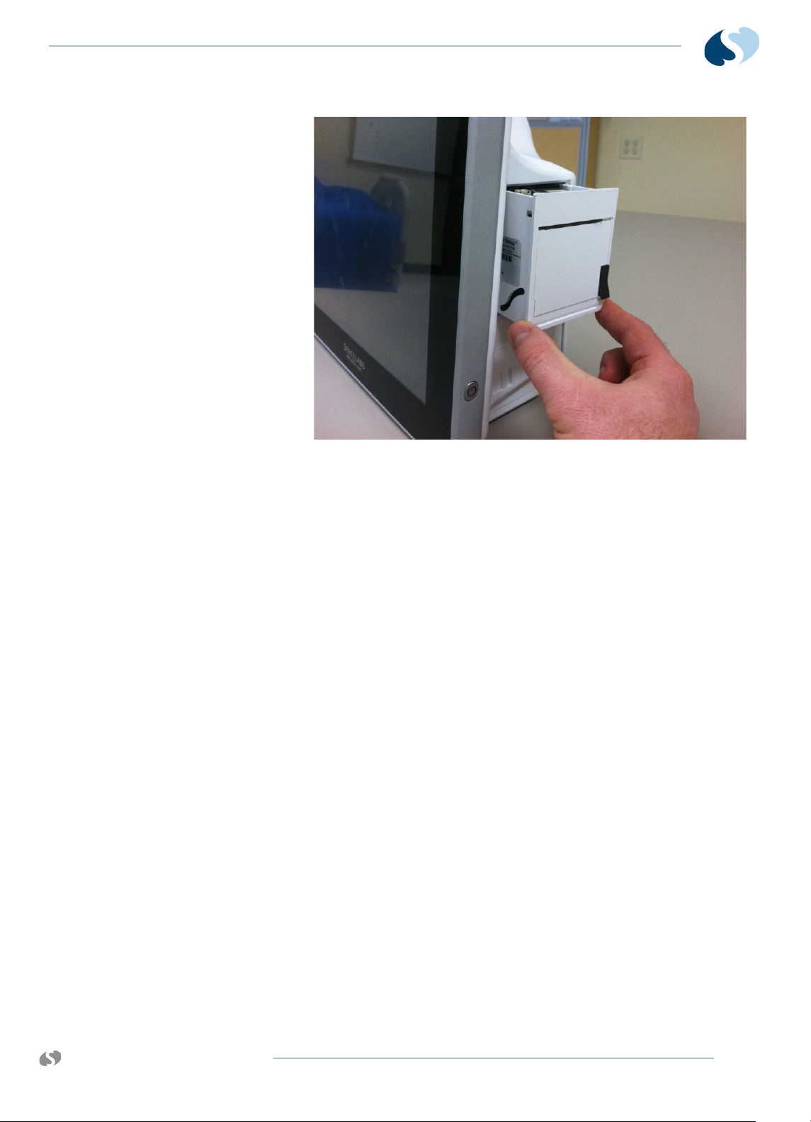
91390 QUBE
M AINTENANCE
Figure 4-25 Recorder Assembly and CPU PCBA
To replace the recorder
Insert Recorder Paper
Two rolls of thermal recorder paper are included with the optional
recorder assembly.
To insert a roll of paper
1 If the recorder assembly is installed, open the printer door.
Loosen the two captive screws. Pull out the assembly at the
top. Refer to Figure 4-25.
2 To reinstall, use the instructions in Step 3 on page 4-28.
1 Press the release bar at the right of the recorder assembly.
The front of the recorder assembly is hinged at the bottom.
Two spoon-shaped arms that hold the paper roll spindle
between them drop down.
2 Unroll a short length of paper from the roll. Orient the roll so
that the paper feeds from the bottom.
3 Slip the paper roll spindle between the plastic arms. Close the
front of the assembly so that the end of the paper roll sticks out
of the recorder assembly.
Dock Connector Covers for Option A
The covers are snap-on and snap-off, and can be removed by hand.
www.spacelabshealthcare.com
4-29
Page 84

91390
Docking Connector Plug
QUBE
Figure 4-26 Docking Connector Plug
Removal of Pod Interface PCBA for Options A and B
Refer to Drawing 7 for details and find the replacement assembly kit
listed with the Parts List on page 6-2.
1 Power OFF the monitor and remove the battery or batteries.
2 Remove the module from the monitor.
3 Disconnect the POD interface cable (Item 14).
M AINTENANCE
4 Use a right-angle Phillips head screw driver to remove the six
screws (items 27) while you hold the POD interface bracket (item
48) to the rear enclosure.
5 Remove the POD interface bracket. Do not remove the "Ball
Stud" clips.
6 Remove the four terminal washers (items 18).
7 You can gently pull on the PCBA if necessary, as there is a gasket
sealing the PCB to the rear enclosure.
8 Inspect the POD interface PCBA gasket and "Ball Studs" for any
visible damage. Replace them if necessary.
Reinstallation of the Pod Interface PCBA
1 Before you install the new POD interface PCBA again, make sure
that the POD interface gaskets and ball studs are not damaged.
Replace them as necessary.
2 If not already completed, attach the POD interface gaskets (Items
38 and 39) to the rear enclosure.
3 Place the monitor on a flat surface, so that the display side faces
up. Place the POD Interface PCBA and terminal washers in their
respective locations.
4-30
4 Place the two "Ball Stud" clips (Item 36) in place, and the use the
six screws (Items 27) to attach the POD Interface bracket (Item
48).
5 Reconnect the POD interface cable (Item 14).
6 Perform the retest procedure. Refer to Monitor Functional Tests
on page 4-5.
www.spacelabshealthcare.com
Page 85

91390 QUBE
M AINTENANCE
Docking Station PCBA Replacement Procedures for Option A
Required Tools and Parts
• Antistatic mat with wrist strap
• #1 and #2 Phillips-head screwdriver
• 3/16-inch nut driver
• Docking Station PCBA (P/N 670-1558-xx)
Caution:
Before you begin any disassembly procedures, disconnect the AC cord
from the AC power receptacle. Make sure to use the proper procedures to
handle electrostatic-sensitive devices.
Docking Station
www.spacelabshealthcare.com
Figure 4-27 Qube Docking Station
1 Disconnect all cables from the docking station.
2 Turn the docking station over. Remove the six screws from the
docking station cover plate. Refer to Figure 4-28 on page 4-32.
4-31
Page 86

91390
QUBE
M AINTENANCE
Figure 4-28 Docking Station Bottom View
3 Remove the docking station cover plate. Set it aside.
4 Remove the connection J70 (docking station release button LED
power) from the docking station PCBA. Refer to Figure 4-29.
5 Remove the seven (7) screws from the monitor docking PCBA.
Refer to Figure 4-29.
Figure 4-29 Docking Station Enclosure
6 To make room to slide out the docking station PCBA, loosen the
six screws on the latch assembly in order. Refer to Figure 4-30 on
page 4-33.
4-32
www.spacelabshealthcare.com
Page 87

91390 QUBE
M AINTENANCE
Figure 4-30 Latch Docking Station
7 Remove the six (6) connector standoff screws from the back of
the docking station with a nut driver. Refer to Figure 4-31.
Figure 4-31 Docking Station Connectors
8 Turn the docking station back over. Carefully slide out the
docking station PCBA. Do not damage the connectors.
9 Install a new docking station PCBA in the reverse order.
10 Perform functional tests in accordance with the monitor
functional tests. Refer to Figure 4-30.
Replace the Docking Station Latch
1 Disconnect all cables from the docking station.
2 Turn the docking station over. Remove the six screws from the
docking station cover plate. Refer to Figure 4-27 on page 4-31.
3 Remove the docking station cover plate. Set it aside.
4 Remove the connection J70 (LED wiring assembly) from the
docking station PCBA. Refer to Figure 4-32.
www.spacelabshealthcare.com
4-33
Page 88

91390
QUBE
M AINTENANCE
Figure 4-32 LED Wiring Assembly Connection J70
5 Remove the six (6) screws on the latch assembly. Refer to Figure
4-30 on page 4-33.
6 Carefully remove the pins, springs, and washers. Refer to Figure
4-30 on page 4-33.
7 Remove the two (2) screws from the push-button support
bracket.
8 Remove the push button.
9 Install the new latch assembly in reverse order.
10 Make sure that the docking station accepts the monitor correctly.
Replace the Docking Station Push Button
1 Do the steps to replace the docking station latch.
2 Remove the screws holding the push-button assembly. Refer to
Figure 4-30 on page 4-33.
3 Replace with a new push button.
4 Reassemble the unit in reverse order.
5 Make sure that the push button operates correctly by docking
and undocking a monitor.
4-34
www.spacelabshealthcare.com
Page 89

91390 QUBE
Cleaning
M AINTENANCE
To clean the case, wash it with mild soap and water or use Plast-NGlas cleaner. To clean the electronic connectors and contacts, use
TF solvent as necessary.
Caution:
• Do not autoclave.
• Never use solvents, acetone, abrasive cleaning agents, or abrasive
cleaning pads.
• Only use approved cleaning agents, including 70% alcohol, soap and
water, green soap, or 10% bleach solution.
• Do not directly spray liquids into the recorder, module, or battery
compartments.
Refer to the XPREZZON and qube Bedside Monitoring Operations
Manual (P/N 070-2112-xx) for more information.
www.spacelabshealthcare.com
4-35
Page 90

91390
QUBE
M AINTENANCE
4-36
www.spacelabshealthcare.com
Page 91

91390 QUBE
Troubleshooting
Overview
The first several sections describe the available diagnostics features
and how to use them. Next is a section which lists diagnostics failure
messages and the suggested corrective actions. The last section
gives specific troubleshooting steps which can be used to isolate
failures.
The troubleshooting procedures in this chapter isolate equipment
problems to a Field Replaceable Unit (FRU).
The following items are field replaceable:
• PCBA, CPU, P/N 670-1573-xx (all options)
• PCBA, Interconnect, P/N 670-1481-xx (options A and B)
PCBA, Interconnect, P/N 670-1644-xx (option C)
• PCBA, Monitor Dock, P/N 670-1521-xx (option A)
PCBA, Monitor Dock, P/N 670-1647-xx (options B and C)
• PCBA, Connector, P/N 670-1522-xx (option A)
PCBA, Connector, P/N 670-1645-xx (options B and C)
• PCBA, Battery Connector, P/N 670-1555-xx (option A)
PCBA, Battery Connector, P/N 670-1658-xx (options B and C)
• External DC Power Supply, P/N 119-0552-xx (all options)
• Pod interface, P/N 670-1550-xx (options A and B)
Pod interface, P/N 670-1559-xx (option C)
Caution:
www.spacelabshealthcare.com
Observe precautions for handling electrostatic-sensitive devices!
5-1
Page 92

91390
QUBE
Notes:
• Never touch electrostatic-sensitive electronic components
• All static-sensitive electronic components are packaged in
Required Tools and Parts
The items that follow are necessary for troubleshooting and repair:
• Anti-static mat with wrist strap
• #1 and #2 Phillips-head screwdriver
• Standard flat screwdriver
•Multimeter
TROUBLESHOOTING
without following proper anti-static procedures, including the
use of an ESD wrist band and mat. An electrostatic discharge
from your fingers can permanently damage electronic
components and cause latent failures.
static-shielding bags. Keep the bag for repackaging the
component to store it or return it to Spacelabs Healthcare for
any reason.
System Startup
The System Boot window is shown when the monitor is first
powered ON.
5-2
Figure 5-1 System Startup Window
www.spacelabshealthcare.com
Page 93

91390 QUBE
System
When this screen is shown, the monitor automatically begins
Power-On diagnostics. Any diagnostic failures are reported in the
upper window. If no serious diagnostics failures are encountered, the
monitor continues past this screen and starts normal monitor
operation.
You can halt the booting operation during the 4-3-2-1 countdown
and a Boot menu can be shown.
The Boot menu and the power-ON diagnostics are described in the
sections that follow.
Power-ON Diagnostics
Power-ON diagnostic tests make sure of system hardware integrity
during power-on and can often help isolate and troubleshoot a
problem. Most of these tests can also be done in the extended
diagnostic mode.
TROUBLESHOOTING
The diagnostics done at power-ON include:
• CPU—reads and writes control registers and does an internal
wraparound of one serial communication controller channel.
• DRAM read/write—reads and writes DRAM above 1 MB.
• Real-time clock—makes sure that the clock is running.
• GDS SRAM—reads and writes all of the SRAM, nondestructively.
• Video—tests the video memory, video controller, H-sync, and
blue video signals.
• Ethernet—reads and writes control registers.
• Flash checksum—checksums all flash memory.
• Touchscreen—tests the touchscreen controller.
• Audio—reads and writes control registers in the codec.
Power-ON diagnostic failures are reported in the upper portion of
the System Startup screen. For more information, refer to Boot
Menu on page 5-4.
Any error that occurs during one of these tests is logged in the
nonvolatile configuration memory. To retrieve the log, refer to Error
Log on page 5-11.
You can halt the booting operation during the 4-3-2-1 countdown to
enter the Boot menu. A description of the Boot menu is given in the
next section.
www.spacelabshealthcare.com
5-3
Page 94

91390
QUBE
Boot Menu
TROUBLESHOOTING
The Boot menu can only be accessed during a system startup (cold
boot). It allows access to several basic configuration menus and
functions of the monitor, including Extended Diagnostics. If the
serial port is configured for DIAGNOSTICS in the Biomed Menu, all
text shown on the screen is also output to the serial port.
To access the Boot menu if the display is functional
1 Power ON the monitor and wait for the 4, 3, 2, 1 countdown
(Refer to Figure 5-1 on page 5-2).
2 Before the countdown expires, do the following step based on
what equipment you use that is connected to the serial port:
• Touchscreen — Touch the bottom left and then the bottom
right corner (not simultaneously) of the screen (Figure 5-2
on page 5-4).
• Mouse — Click the left and right mouse buttons
simultaneously.
• Terminal or Keyboard — Press CTRL+D.
5-4
Figure 5-2 Touch Points to Enter Extended Diagnostics
www.spacelabshealthcare.com
Page 95
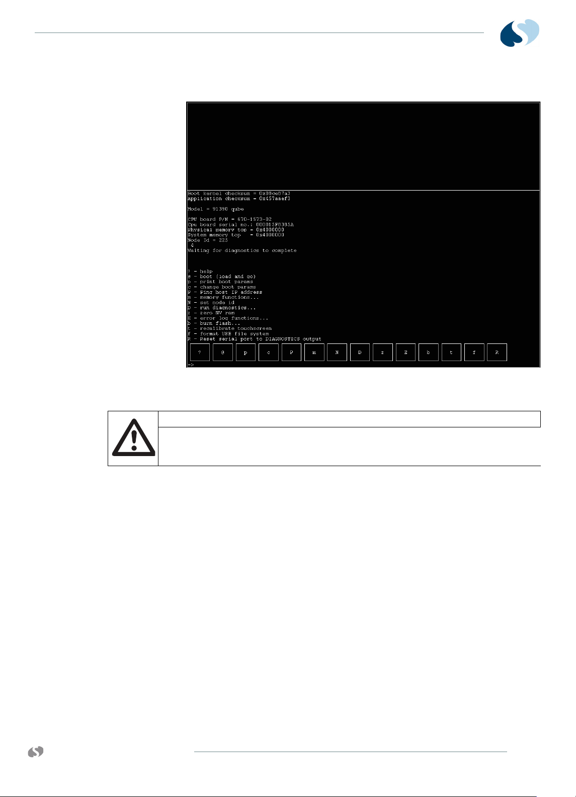
91390 QUBE
TROUBLESHOOTING
The Boot menu appears as shown in Figure 5-3.
Figure 5-3 Boot Menu
Caution:
Use caution when you do the functions in this menu. The user should only
execute Diagnostics (D) or use the Error Log (E). The rest of the features
are only for qualified Spacelabs Healthcare field service engineers.
Note:
All menu selections are case-sensitive when using a keyboard or
terminal.
The following keys are available in the Boot menu:
? — Provides an explanation of this menu.
@ — Starts the monitoring application.
p — Prints the boot parameters
c — Allows boot parameters to be changed.
P — Allows this monitor to ping the host IP address [host inet
(h)].
m — Requires a data key (Spacelabs Healthcare Field Service
Engineers only). The Memory menu shows (Memory Menu). This
menu has limited value in the field.
www.spacelabshealthcare.com
N — Allows the node ID to be changed and sets the monitor ID
number in Network Setup.
D — The Main Diagnostic menu shows (Main Diagnostic Menu).
5-5
Page 96

91390
QUBE
TROUBLESHOOTING
z — With a data key present (Spacelabs Healthcare Field Service
Engineers only): Zeros and initializes the NVRAM with factory
defaults. All Options and network settings revert to factory
defaults.
Without a data key present: Zeros and initializes the NVRAM, but
maintains the Options settings, TCP/IP settings and Node
(Monitor) ID.
E — Displays the Error Log Functions menu, which allows the
error log to be cleared or dumped to the screen and serial port.
b — Displays the Burn Flash menu, which allows new boot kernel
or application software to be loaded over the network and
burned into flash memory (Spacelabs Healthcare Field Service
Engineers only).
t — Recalibrates the touchscreen (monitor automatically resets).
f — Formats the USB device on the CPU board assembly.
R — Resets the serial port to DIAGNOSTICS output. This allows
the use of the serial terminal to access and control
DIAGNOSTICS.
Boot Parameters
To display the boot parameters, touch the p (lower-case) key in the
Boot menu. Figure 5-4 and Figure 5-5 shows the out-of-the-box
factory default settings. By default, the gateway inet parameter is
not shown. Touch Continue to return to the Boot menu.
If any of the boot parameters are incorrect, touch c from the Boot
menu. Each parameter setting is presented, one at a time. If the
setting is correct, touch the <ENTER> key to go on. If the setting is
incorrect, use the <Del> key to delete the incorrect text, and then
retype the entry using the onscreen keyboard. Touch @ - boot (load
and go) to reboot the monitor with the new settings.
5-6
Figure 5-4 Boot Parameters Menu with Factory Default Settings
(v3.01.00)
www.spacelabshealthcare.com
Page 97

91390 QUBE
Figure 5-5 Boot Parameters Menu with Factory Default Settings
Extended Diagnostics
TROUBLESHOOTING
(v3.03.00 and higher)
Extended diagnostic tests, like the power-ON diagnostics, can be
used to troubleshoot and isolate many system failures. The types of
tests and features available in the extended diagnostics are:
• Power-ON diagnostics.
• Interactive tests and read/write memory tests that are not
appropriate during power-ON diagnostics.
•Touchscreen calibration and data dump utilities.
• System data dump and system reset utilities.
The diagnostic menus allow most of these tests to be run
individually or all at once. If Loop mode is activated, a test can be
executed in a continuous loop. If Halt On Error mode is activated,
the looping stops when a diagnostic failure is detected. To avoid
false failures, do not use the touchscreen, mouse, or keyboard while
the diagnostic tests execute.
Any error that occurs during one of these tests is logged in the nonvolatile memory (NVRAM). Refer to Error Log on page 5-11 to
retrieve the log.
For detailed information on extended diagnostics and how to run
them, Refer to Diagnostic Menus on page 5-8.
www.spacelabshealthcare.com
5-7
Page 98
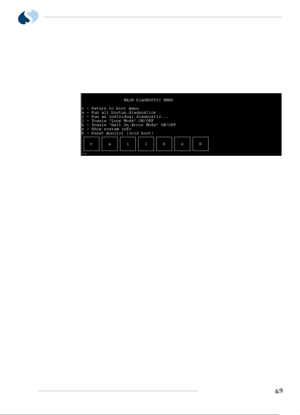
91390
QUBE
Diagnostic Menus
Main Diagnostic Menu
To show the Main Diagnostic menu (Main Diagnostic Menu), touch
the D key in the Boot menu.
TROUBLESHOOTING
Figure 5-6 Main Diagnostic Menu
The following functions are available in the Main Diagnostic menu:
r — Returns to the Boot menu.
a — Runs the same tests that run during power-ON diagnostics.
i — The Individual Diagnostic menu shows (Individual Diagnostic
Menu).
l — Toggles Loop mode ON or OFF. When Loop mode is ON,
selected test or tests are run continuously, until power is toggled
OFF.
h — Toggles Halt On Error mode ON or OFF. The system stops
on the test that failed, and displays the results on the screen.
s — Shows system information, including power supply and
battery status details, address spaces and variables used in the
system.
R — Causes a cold boot reset just like toggling the power OFF.
5-8
www.spacelabshealthcare.com
Page 99

91390 QUBE
Individual Diagnostic Menu
To display the Individual Diagnostic menu, touch the i key in the
Main Diagnostic menu. Tests designated by the asterisk (*) are the
same tests that are executed during power ON. Except where noted,
these tests are pass/fail only.
The following keys are available in the Individual Diagnostic menu:
TROUBLESHOOTING
Figure 5-7 Individual Diagnostic Menu
r — Returns to the Main Diagnostic menu.
c — Tests certain CPU functions, similar, but not identical to, the
power-ON CPU test.
a — Runs the power-ON audio diagnostic. An audible tone is
heard at the completion of the test.
w — Runs the power-ON wireless LAN diagnostic (if installed).
e — Runs the power-ON Ethernet test.
R — Makes sure that the real-time clock is running.
m — Displays the Memory menu (Memory Menu).
v — The Video menu shows (Video Menu).
t — The Touchscreen menu shows. Interactive test.
X — Runs the DSB diagnostics.
f — Shows the Fan Control menu (v3.03.00 only). Interactive
test. Fan control is returned to normal operations upon exiting
the Fan menu.
s — Safety Circuit test (requires -02 or higher CPU PCBA, and
v3.03.00 or higher installed). Interactive test.
www.spacelabshealthcare.com
5-9
Page 100

91390
QUBE
Memory Menu
TROUBLESHOOTING
To show the Memory menu, touch the m key in the Individual
Diagnostic menu. Tests designated by the asterisk (*) are the same
tests that are executed during power ON. These tests are pass/fail
only.
Figure 5-8 Memory Menu
The keys that follow are available in the Memory menu:
r — Returns to the Individual Diagnostics menu.
d — Runs a Dynamic RAM (DRAM) test, similar to the power-ON
DRAM test, but tests only the memory not in use by the boot
kernel.
f — Performs the power-ON Flash checksum.
F — Performs a read/write test on the application area of flash
memory, which overwrites the application software. Reload the
software after the test. Requires a data key (Spacelabs
Healthcare Field Service Engineers only).
g — Runs the power-ON GDS SRAM test. The SRAM stores the
trend data (GDS) for the patient.
n — Performs a checksum on NVRAM.
N — Requires a data key (Spacelabs Healthcare Field Service
Engineers only). Performs a read/write test of the NVRAM, which
overwrites configuration parameters in NVRAM. After the
NVRAM test completes, NVRAM must be zeroed with the data
key attached. The boot parameters and sysgen values must be
reentered.
5-10
www.spacelabshealthcare.com
 Loading...