

Page 1
BleaseSirius
Anesthetic Machine
Technical Manual
073-0227-00/REV. D
1
Page 2

2
Page 3
BleaseSirius
Anesthetic Machine
With 700/900 Series Ventilators
Technical
Manual
MODIFICATIONS LABEL
ECO A
REV B
REV C
REV D
REV E
PR023288
REV F REV G REV H REV I REV J
Spacelabs Healthcare Ltd.
1 Harforde Court • John Tate Road • Hertford
SG13 7NW • United Kingdom
Tel: +44 (0)1992 507700
Fax: +44 (0)1992 501213
e-mail (enquiries): advsales@spacelabs.com
e-mail (technical): advsupport@spacelabs.com
www.spacelabshealthcare.com
PR032030
PR033225
PR034475
Part Number: 073-227-00
Rev. D/ July 2013
3
Page 4

4
Page 5

Important
Read this manual before operating or servicing the machine.
For all users and Service Personnel, refer to the User Manual before operating
the machine.
© Copyright 2013, Spacelabs Healthcare Limited.
All rights reserved. The information contained in this publication may not be
used for any other purpose than that for which it was originally supplied.
This publication may not be reproduced in part or in whole without the written
consent of Spacelabs Healthcare.
5
Page 6

This page is intentionally left blank
6
Page 7

Contents
Chapter 1-Technical Description ............................................................... 19
1.1 Description .........................................................................................................21
1.1.1 General ................................................................................................21
1.1.2 The Frame ............................................................................................21
1.1.3 Pneumatic Assembly ............................................................................21
1.1.4 The Monitor Shelf .................................................................................21
1.2 Specifi cation ......................................................................................................24
1.2.1 Machine Dimension..............................................................................24
1.2.2 Work Surface Dimensions ....................................................................24
1.2.3 Monitor Shelf Dimensions ....................................................................24
1.2.4 Maximum Loading ................................................................................24
1.3 Pneumatics ........................................................................................................25
1.3.1 Gas-Specifi c Color Specifi cations ........................................................25
1.3.2 Gas Supply Combinations....................................................................25
1.3.3 Common Gas Outlet ............................................................................25
1.4 Technical/Performance Specifi cation ..............................................................26
1.4.1 Controls ................................................................................................26
1.4.2 Ventilator ..............................................................................................26
1.4.3 Alarms / Indicators ...............................................................................26
1.4.4 Regulator Safety Valve Settings ...........................................................26
1.4.5 Electrical ...............................................................................................27
1.4.6 Supplies ...............................................................................................28
1.4.7 Environmental ......................................................................................28
Chapter 2-Overview .................................................................................... 29
2.1 Description of the Ventilator ...........................................................................31
2.1.1 Overview ..............................................................................................31
2.1.1.1 PEEP ...................................................................................................31
2.1.1.2 Trigger .................................................................................................32
2.1.1.3 Support Pressure .................................................................................32
2.1.1.4 Fresh Gas Compensation ....................................................................32
7
Page 8

Contents
2.1.1.5 Oxygen ................................................................................................32
2.1.1.6 Tidal Volume ........................................................................................32
2.1.1.7 Minute Volume .....................................................................................32
2.1.1.8 Expired Tidal volume ...........................................................................32
2.1.1.9 BPM (Frequency Control) ....................................................................32
2.1.1.10 I:E Ratio ...............................................................................................33
2.1.1.11 Pressure Limit ......................................................................................33
2.1.1.12 Peak Pressure .....................................................................................33
2.1.1.13 Mean Pressure ....................................................................................33
2.1.1.14 Compliance ..........................................................................................33
2.1.1.15 Volume Measurement ..........................................................................33
2.1.1.16 Oxygen Measurement .........................................................................33
2.2 Pre-use Test .......................................................................................................34
2.2.1 Fresh Gas ............................................................................................34
2.2.2 Compliance ..........................................................................................34
2.2.3 Compensation ......................................................................................36
2.2.4 Mode Dependant Features ..................................................................37
2.3 Principles of Operation .....................................................................................41
Chapter 3-Planned Maintenance ............................................................... 43
3.1 Planned Maintenance ........................................................................................45
3.2 Routine Maintenance and Service Check. ......................................................48
3.2.1 Fitting Planned Maintenance Kit PN 14000511 ....................................48
3.2.2 Bodoc Seals .........................................................................................48
3.2.3 Backbar Seals ......................................................................................48
3.2.4 Backbar Dzus Springs..........................................................................48
3.2.5 Absorber Stop/’O’ Ring ........................................................................48
3.2.6 Pipeline Fitting and ‘O’ Ring .................................................................48
3.3 AGSS Probe and Float for Spacelabs AGSS
PN 14200018, (if Fitted) ......................................................................50
3.4 Bellows Base/Canister ......................................................................................51
3.5 Pop-off Valve ......................................................................................................51
8
Page 9

Contents
3.6 Absorber .............................................................................................................53
3.6.1 Valve Covers ........................................................................................53
3.6.2 Manometer ...........................................................................................53
3.6.3 Canister Seals ......................................................................................53
3.6.4 Fitting 4 Year Planned Maintenance Kit, PN 14000512 .......................54
3.6.5 Ventilator Filter ....................................................................................54
3.6.5.1 Two Valve Version Only (on units before Feb 2009) ............................54
3.6.5.1 Valve Block on units after Feb 2009 ........................................................54
3.6.6 Cylinder Regulator Pressure Relief Valve, PN 019-0831-00 ................55
3.7 CLEANING ......................................................................................................56
Chapter 4-System Checks ......................................................................... 59
4.1 Overview.............................................................................................................61
4.2 Tools and Test Equipment Required ...............................................................61
Parts Required........................................................................................................62
4.3 Visual Inspection ...............................................................................................65
4.4 Pipeline Leak Test .............................................................................................66
4.5 Cylinder Leak Test .............................................................................................68
4.6 Regulator Output Test .......................................................................................68
4.7 On/Off Switch Gas Cut Off Test .......................................................................70
4.8 Oxygen Supply Failure Test .............................................................................70
4.9 High Pressure Outlet Test .................................................................................71
4.9.1 Parts required ...............................................................................................71
4.10 Hypoxic Guard and Flow Control Accuracy Tests .......................................72
4.11 Backbar Tests ..................................................................................................74
4.11.1 Pressure Build-up Test ................................................................................74
4.11.2 T1 Backbar Test ..........................................................................................75
4.11.3 T2 Backbar test ............................................................................................76
4.12 Common Gas Outlet (CGO) Test ....................................................................77
4.12.1 Oxygen Flush Test ......................................................................................77
4.12.2 Pressure Relief Valve Test ..........................................................................77
9
Page 10

Contents
4.13 Suction System Test .......................................................................................78
4.14 Absorber Tests.................................................................................................79
4.14.1 Expiratory Valve Leak Test .........................................................................79
4.14.2 Inspiratory Valve Leak Test .........................................................................80
4.14.3 APL Valve Check ........................................................................................81
4.15 Ventilator Test ..................................................................................................83
4.16 Vaporizer Output Concentration Check ........................................................89
4.17 Electrical Safety Test .......................................................................................91
4.18 Complete the BleaseSirius Checkout Sheet .................................................92
Chapter 5-Detailed Repair Procedures ..................................................... 93
5.1 Removal/Replacement Instructions.................................................................95
5.1.1 Removal of Outer Cases (on units up to Jan 2009) .............................95
5.1.2 Removal of Outer Cases (on units after Jan 2009) .............................97
5.2 Mechanical Hypoxic Guard Block ..................................................................103
5.2.1 Introduction ........................................................................................103
5.2.2 Flow Meter Removal...................................................................................104
5.2.3 Replacement of Hypoxic Guard Block (FR135025) ...........................107
5.2.4 Calibration of Hypoxic Guard System ................................................108
5.2.5 Calibration procedure .........................................................................109
5.3 Setting Oxygen Basal Flow ............................................................................110
5.4 Nitrous Oxide and Air Flow Valve Leak Test ................................................. 111
5.5 Mechanical Hypoxic Guard Regulators, Adjustment and Output Check ... 115
5.5.1 Hypoxic Regulator Replacement (for units manufactured before Feb
2009) .................................................................................................. 117
5.6 Cylinder Regulator Pressure Relief Valve Replacement ...............................122
Replace the Cylinder Regulators.......................................................................123
5.7 Backbar Valve Replacement ...........................................................................129
5.8 Common Gas Outlet (CGO) Removal/Replacement (up to Feb 2009) ........130
5.9 Alarm Block Removal/Replacement ..............................................................131
5.9.1 On units Manufactured Before Feb 2009 ...........................................131
10
Page 11

Contents
5.9.2 On units Manufactured After Feb 2009Feb 2009 onwards) ...............132
5.10 Oxygen Flush & Common Gas Outlet Safety Valve Adjustment
(up to Feb 2009) ................................................................................133
5.10.1 Oxygen Flush Adjustment on units sold before July 2010
(Units sold after July 2010 are not adjustable.) ..................................134
5.10.2 Common Gas Outlet (CGO) Removal/ Replacement
(From Feb 2009 onward) ...................................................................135
5.11 ON/OFF Switch (PN FR142028) ...................................................................140
5.10.1 Test Procedure for Microswitches .............................................................145
5.12 Absorber .........................................................................................................146
5.12.1 General ..............................................................................................146
5.12.2 Absorber Interface Manifold Assembly...............................................150
5.12.3 Absorber Alignment ............................................................................151
5.12.4 Standby / Run ....................................................................................151
5.12.5 Absorber Docking...............................................................................152
5.12.6 Setting Ball Catch...............................................................................153
5.13 Internal Absorber ...........................................................................................155
5.13.1 Bellows Interface Gasket ...................................................................158
5.14 Servicing the Bag Arm ..................................................................................159
5.15 Drawer Removal/Replacement .....................................................................164
5.16 Braking System Maintenance.......................................................................167
5.17 Castors Maintenance ....................................................................................168
5.18 Suction Controller Removal/Replacement ..................................................169
5.19 Ventilator ........................................................................................................172
5.19.1 Inspiratory Block Assembly ................................................................172
5.198.2 Ventilator Internal System ..................................................................173
5.19.2.1 Replacement of Major Components .................................................173
5.19.3 Removal of Inspiratory Block (FR137025) .........................................174
5.19.4 Removal of BAV Controller (FR101027) ............................................177
5.19.5 Removal of BAV Power Supply (FR136029) ......................................178
5.19.6 Removal of Front Panel (FR101026) .................................................179
5.19.7 Removal of the Screen (FR812025) ..................................................181
11
Page 12

Contents
5.19.8 Removal of Switch Mode Power Supply (FR136025) ........................182
5.19.9 Removal of Flow Control Valves (up to March 2009) .........................183
5.19.10 Removal of Gas Inlet Module (FR 140026) (up to March 2009) ........184
5.19.11 Replacement of Battery (80300025) ..................................................185
5.19.12 Exchanging of Fuses (EF533789)......................................................186
5.20 Major Component Installation ......................................................................187
5.21 Set up Options ...............................................................................................188
5.22 Fresh Gas Calibration (2) ..............................................................................189
5.23 Absorber fi tted (3) .........................................................................................189
5.24 Sigh (4) 189
5.25 Gas Exhaust (5) .............................................................................................190
5.26 Enable Pre-use Test (6) .................................................................................190
5.27 Touch Calibration (7) .....................................................................................190
5.28 Ventilator Service Mode Passwords ............................................................191
5.28.1 Passwords used in the Service Mode ................................................191
Test Procedure ..................................................................................................199
5.29 Reprogramming .............................................................................................200
5.29.1 Software Upgrade Procedure.............................................................200
5.29.2 To use VentFlash................................................................................201
5.29.3 To upgrade the Language File ...........................................................202
5.29.4 To Upgrade the Ventilator Model ........................................................203
Chapter 6-EFM Option .............................................................................. 205
Chapter 7
Error Codes ................................................................................................ 237
7.1 Error Codes ......................................................................................................239
7.1.1 Error codes on the Blease700/900 series Ventilators ........................239
Chapter 8-Spare Parts .............................................................................. 241
8.1 Parts List ..........................................................................................................243
12
Page 13

Contents
Chapter 9-Notices and Important Information ....................................... 253
9.1 Product Improvement .....................................................................................255
9.2 Responsibilities of the User ...........................................................................255
9.3 Responsibilities of the Manufacturer ............................................................255
9.4 Disclaimer ........................................................................................................256
9.5 Technology Disclaimer / Tamper Proof Seal ................................................256
9.6 Note to Service Personnel ..............................................................................256
9.7 CE Mark 257
9.8 Trademarks and Acknowledgements ............................................................258
9.9 Hazard Notices.................................................................................................259
9.9.1 BleaseSirius Warnings .......................................................................260
9.9.2 Electrostatic Sensitive Devices (ESD) Warnings and Cautions .....262
9.9.3 Cautions .............................................................................................263
9.9.4 Ventilator Warnings ...........................................................................264
9.9.5 Hazard Information.............................................................................265
9.9.6 Cautionary Notices .............................................................................268
9.9.7 Vaporizer Warnings ...........................................................................270
9.9.8 Absorber Warnings ...........................................................................271
9.9.9 Cautionary Notices .............................................................................272
Chapter 10-Schematics ............................................................................ 273
13
Page 14

Figures
Figure 1 - BleaseSirius Anesthetic Machine .............................................................22
Figure 2 - Electrical Labeling ......................................................................................27
Figure 3 - PEEP Diagram ...........................................................................................31
Figure 4 - Ventilator Schematic ..................................................................................38
Figure 5 - Absorber Pneumatic Schematic .................................................................39
Figure 6 - Pneumatic Circuit .......................................................................................40
Figure 7 - BleaseSirius Annual Planned Maintenance Kit
PN 14000511 ......................................................................................46
Figure 8 - BleaseSirius Four Year Planned Maintenance Kit PN 14000512 ..............47
Figure 9 - Pipeline Fitting & ‘O’ Ring...........................................................................49
Figure 10 - AGSS .....................................................................................................50
Figure 11 - Pop-off Valve ............................................................................................51
Figure 12 - Bellows Assembly ....................................................................................52
Figure 13 - Pneumatic Module ...................................................................................54
Figure 14 - Primary Regulator ....................................................................................57
Figure 15 - BleaseSirius Checkout Sheet (PN 073-0301-00 Rev. C) .........................64
Figure 16 - Connect the Pipeline Test Shut-off Valve .................................................66
Figure 17 - N2O Pipeline Gauge .................................................................................67
Figure 18 - Connect Pressure
Measuring Device ...............................................................................69
Figure 19 - Regulator Nut and Set Crew Locations ....................................................69
Figure 20 - Test Hose Assembly .................................................................................71
Figure 21 - Test Hose Connections ............................................................................72
Figure 22 - Connect O2 Analyzer (L) and Tubing to AGSS (R) ...................................73
Figure 23 - Pressure Build-up Test .............................................................................74
Figure 24 - Fit 6 mm Plug ...........................................................................................75
Figure 25 - Steps 5 and 8 ...........................................................................................75
Figure 26 - Step 4: Plug the CGO Taper ....................................................................76
Figure 27 - Steps 6 and 8 ...........................................................................................76
Figure 28 - O2 Flush Test ............................................................................................77
Figure 29 - Connect Pressure Measuring Device.......................................................77
Figure 30 - Suction Gauge and Bowl..........................................................................78
Figure 31 - Expiratory Valve Test Setup .....................................................................79
Figure 32 - Setup for Inspiratory Valve Test ...............................................................80
Figure 33 - Steps 3 & 4 of the Inspiratory Valve Test .................................................81
Figure 34 - Connect a Pressure Measuring Device....................................................81
Figure 35 - Connect the Pressure Sampling Tee .......................................................82
Figure 36 - Step 5: Occlude the Bag Port...................................................................82
Figure 37 - Exhaust Port Location ..............................................................................83
Figure 38 - Step 11: Disconnect Patient Hose ............................................................84
14
Page 15

Figures
Figure 39 - Connect a Flow Measuring Device ..........................................................84
Figure 40A - Change the Flow Sensor Settings .........................................................85
Figure 40B - Pedi Sensor Placement setting..............................................................85
Figure 41 - Connect a Pressure Measuring Device....................................................86
Figure 42 - Step 5: Connect a Reusable Tube ...........................................................89
Figure 43 - Connect a Pressure Sample Tee .............................................................90
Figure 44 - Gas Analyzer Connection ........................................................................90
Figure 45 - Removal of Top Surface ...........................................................................95
Figure 46 - Removal of Screw as Shown ...................................................................96
Figure 47 - Removal of Top Screws as Shown ..........................................................96
Figure 48 - Removal of Front Cover ...........................................................................97
Figure 49 - Front Cover Fixing Screws (on units after Jan 2009) ...............................97
Figure 50 - Front of Machine With Front Cover Removed (Close-up) ........................99
Figure 51 - Rear of Machine .....................................................................................100
Figure 52 - Rear Panels ...........................................................................................101
Figure 53 - Removal of Large Rear Panel ................................................................102
Figure 54 - Flow Meter Removal ..............................................................................104
Figure 55 - BL1 Connector Location.........................................................................105
Figure 56 - Flow Tube Removal ...............................................................................106
Figure 57 - Removal of Screws on Flow Meter Assembly ........................................107
Figure 58 - Rear of Flow Meter Assembly ................................................................107
Figure 59 - Hypoxic Guard fi xing screws ..................................................................108
Figure 60 - Assembled Hypoxic Guard Unit ............................................................. 111
Figure 61 - Exploded View of Hypoxic Guard Components .....................................112
Figure 62 - Flow Block Showing Flow Tube Filters and Tube Lower Inserts ............113
Figure 63 - View of Assembled Hypoxic Guard From Below ....................................114
Figure 64 - Test Points .............................................................................................116
Figure 65 - Pre Feb 2009 Regulator Adjustment ......................................................117
Figure 66 - Rear Panel Screw Locations (8) ............................................................118
Figure 67 - Secondary Gas Test Point Locations .................................................... 118
Figure 68 - Secondary Gas Regulator Locations ....................................................119
Figure 69 - Adjust the Regulator Set Screw ............................................................120
Figure 70 - Primary Regulator Assembly ..................................................................122
Figure 71 - Cylinder Regulator Locations .................................................................123
Figure 72 - Location of Bonnet .................................................................................123
Figure 73 - Diaphragm and Actuator Assemblies .....................................................124
Figure 74 - Valve Cartridge and Relief Valve ...........................................................124
Figure 75 - Regulator Service Kit .............................................................................125
Figure 76 - Valve cartridge and Seal Ring ................................................................125
15
Page 16

Figures
Figure 77 - Assemble the Spring, Spring Rest and Bonnet ......................................126
Figure 78 - Slip Ring Location ..................................................................................126
Figure 79 - Diaphragm Assembly .............................................................................126
Figure 80 - Fit the Actuator Assembly ......................................................................127
Figure 81 - Attach the Bonnet to the Regulator ........................................................127
Figure 82 - Fit the Relief Valve to the Regulator ......................................................128
Figure 83 - Location of Valve Retaining Screws .......................................................129
Figure 84- Backbar Valve .........................................................................................129
Figure 85 - CGO Block (up to Feb 2009)..................................................................130
Figure 86 - Alarm Block Removal (up to Feb 2009) .................................................131
Figure 87 - Alarm Block Removal (Feb 2009 onwards) ............................................132
Figure 88 - CGO Adjustment (up to Feb 2009) ........................................................133
Figure 89 - Valve Adjuster and Disc Removed (up to Feb 2009) .............................134
Figure 90 - CGO Block (Feb 2009 onwards) ............................................................135
Figure 91 - Location of (4) Suction Plate Screws .....................................................136
Figure 92 - Location of (3) ACGO Assembly Screws ...............................................136
Figure 93 - Location of 6 mm Tubing ........................................................................136
Figure 94 - Location of 8 mm Tubing ........................................................................137
Figure 95 - Location of 6 mm Tubing ........................................................................137
Figure 96 - Location of 8 mm Stem ..........................................................................137
Figure 97 - Location of Microswitch ..........................................................................138
Figure 98 - ACGO Tubing Orientation ......................................................................138
Figure 99 - ACGO Switch Set to Absorber ...............................................................139
Figure 100 - A.C.G.O Ventilator Screen Display ......................................................139
Figure 101 - Microswitch Components .....................................................................140
Figure 102 - Ventilator Wire Orientation ...................................................................141
Figure 103 - NC Valves (PN 214-1089-00) ..............................................................142
Figure 104 - 4-6 mm Increaser (PN 54200184) and
6-5 mm Reducer (PN 54200110) ......................................................142
Figure 105 - 5 mm Tubing (1) and 6 mm Tubing (2) .................................................143
Figure 106 - Tubing Diagram ....................................................................................144
Figure 107 - Tighten Two Screws .............................................................................145
Figure 108 - Absorber Interface Manifold Assembly .................................................150
Figure 109 - ‘P’ Clip ..................................................................................................151
Figure 110- Absorber Prongs....................................................................................152
Figure 111 - Micro Switch .........................................................................................152
Figure 112 - Setting Ball Catch .................................................................................153
Figure 113 - Lock Screw Insertion ............................................................................154
Figure 114 - Absorber Molding 01 ............................................................................155
Figure 115 - Absorber Molding 02 ............................................................................155
16
Page 17

Figures
Figure 116 - Absorber Molding 03 ............................................................................156
Figure 117 - Absorber Molding 04 ............................................................................156
Figure 118 - Internal view of Absorber Moldings ......................................................157
Figure 119 -Valve Arc ...............................................................................................157
Figure 120 - Bellows Interface Gasket Fixing Screws ..............................................158
Figure 121 - Gasket Removed .................................................................................158
Figure 122 - Drawer Mechanism ..............................................................................164
Figure 123 - Location of Drawer Mechanism and Removal .....................................165
Figure 124 - Drawer Mechanism ..............................................................................166
Figure 125 - Drawer Re-Assembly ...........................................................................166
Figure 126 - Pedal Screw Location ..........................................................................167
Figure 127 - Hex Bar ................................................................................................167
Figure 128 - Hex Bar Removal .................................................................................167
Figure 129 - Location of Caster Retaining Screw .....................................................168
Figure 130 - Caster Removal ...................................................................................168
Figure 131 - Suction Controller Removal / Replacement .........................................169
Figure 132 - Suction Controller in Place ...................................................................170
Figure 133 - Electrical Fuses ....................................................................................171
Figure 134 - Ventilator Case Top ..............................................................................172
Figure 135 - Inside the Ventilator (Top View) ...........................................................173
Figure 136 - View of Removed Inspiratory Block .....................................................176
Figure 137 - View of BAV Controller .........................................................................177
Figure 138 ..........................................................................................................178
Figure 139 ..........................................................................................................178
Figure 140 - Ventilator Control Knob ........................................................................179
Figure 141 - Front Panel Retaining Screws..............................................................180
Figure 142 - Front Panel (Rear View) .......................................................................180
Figure 143 - Gas Inlet Module ..................................................................................184
Figure 144 - Replace the Battery..............................................................................185
Figure 145 - Replace the Fuses ...............................................................................186
Figure 146 - VentFlash Screen .................................................................................201
Figure 147 - VentFlash Sync Screen ........................................................................201
Figure 148 - VentFlash Check Language Screen ....................................................202
Figure 149 - EFM Components ................................................................................205
Figure 150 - System Information, Page 2 .................................................................209
Figure 151 - EFM Hypoxic Guard Block Assembly ..................................................210
Figure 152 - EFM-Machine Retaining Screws ........................................................211
Figure 153 - Ribbon Cable, Power Connector and Light Pipe Locations ...............211
Figure 154 - Flow Tube Locations ..........................................................................212
Figure 155 - Flow Sensor Screw Locations ............................................................212
17
Page 18

List of Schematics
Figure 156 - Banjo Fitting .........................................................................................212
Figure 157 - Hypoxic Guard Retaining Screws ........................................................213
Figure 158 - Screen Retaining Screws .....................................................................214
Figure 159 - Screen-Circuit Board Connectors (3) ...................................................215
Figure 160 - Circuit Board Screws (6) ......................................................................217
Figure 161 - Flow Sensor .........................................................................................218
Figure 162 - Software Update Panel ........................................................................220
Figure 164 - Exit Panel .............................................................................................222
Figure 163 - Confi guration Panel..............................................................................222
Figure 165 - Diagnostics Panel ................................................................................223
Figure 166 - Detect Sensors Display ........................................................................224
Figure 167 - Touch-Screen Panel .............................................................................226
Figure 168 - Exit Panel .............................................................................................227
Schematic 1 - Title Block ...........................................................................................................218
Schematic 2 - SOM Interface ....................................................................................................219
Schematic 3 - Power .................................................................................................................220
Schematic 4 - I2C Sensors ........................................................................................................221
Schematic 5 - Sensors ..............................................................................................................222
Schematic 6 - LCD Digital .........................................................................................................223
Schematic 7 - LCD/LCD Power .................................................................................................224
Schematic 8 - SD Card ..............................................................................................................225
Schematic 9 - Development Circuits .........................................................................................226
Schematic 10 - 10110326 Pressure Interface Board - Master .................................................265
Schematic 11 - 10110326 Pressure Interface Board - Transducers ..........................................266
Schematic 12 - 10110326 Pressure Interface Board - Patient Flow ..........................................267
Schematic 13 - 10110326 Pressure Interface Board - Fresh Gas ..........................................268
Schematic 14 - 10110375 Blease LVDS Display Interface sht. 1 of 4 ......................................269
Schematic 15 - 10110375 Blease LVDS Display Interface sht. 2 of 4 ......................................270
Schematic 16 - 10110375 Blease LVDS Display Interface sht. 3 of 4 ......................................271
Schematic 17 - 10110375 Blease LVDS Display Interface sht. 4 of 4 ......................................272
Schematic 18 - 10110376SCH Power Supply Board ...............................................................273
Schematic 19 - 10110377SCH Controller Board, CPU .............................................................274
Schematic 20 - 10110377SCH Controller Board, Alarms ..........................................................275
Schematic 21 - 10110377SCH Controller Board, Connect ........................................................276
Schematic 22 - 10110377SCH Controller Board, Analogue ......................................................277
Schematic 23 - 10110377SCH Controller Board, I/O Circuits ...................................................278
Schematic 24 - 10110377SCH Controller Board, PWM ............................................................279
Schematic 25 - 10110377SCH Controller Board, Xilinx PWM and I/O ......................................280
Schematic 26 - 13600381 Cable Assy Sirius Vent Interface sht 1of 2 ......................................281
Schematic 27 - 13600381 Cable Assy Sirius Vent Interface sht 2of 2 ......................................282
Schematic 28 - 13600379SCH Sirius Power Distribution 110VA...............................................283
Schematic 29 - 13600379SCH Transformer Interconnections & Soft-Start PCB - 110V ...........284
Schematic 30 - 13600379SCH Transformer Interconnections & Soft-Start PCB - 230V ...........285
18
Page 19

BleaseSirius
Anesthetic Machine
Chapter 1
Technical Description
19
Page 20

Technical Description
20
Page 21

Technical Description
1.1 Description
1.1.1 General
The BleaseSirius anesthetic machines contain all the pneumatic circuitry,
controls, monitoring, ancillaries and storage required to control, distribute and
mix medical gases and anesthetic agents in order to deliver them to a patient
system.
The BleaseSirius anesthetic machine is based on the Frontline machines. The
BleaseSirius has enhanced components and new features and improvements.
The BleaseSirius anesthetic machine is designed to comply with the following:
ASTM F-1850, UL 60601-1, ISO 5358, IEC 60601-1, IEC 60601-2-13, BS EN
740 and other International Standards.
The BleaseSirius machine consists of the major components described below
(See Figure 1).
1.1.2 The Frame
The frame is made of steel supported on a cast aluminum base with four castors,
there is a brake pedal at the bottom of the trolley. The steel frame is covered by
moldings with a painted fi nish.
1.1.3 Pneumatic Assembly
The frame contains the pneumatic assembly. The pneumatic unit contains the
gas supply inputs, the pneumatics that regulate the supply pressures to a usable
pressure, the oxygen failure alarm and its logic circuitry, the common gas outlet,
the user controls and the pneumatic power outlets. Above the work surface are
the cylinder contents and pipeline pressure gauges, fl ow control valves, hypoxic
guard and fl owblock assemblies, the vaporizer back bar and the uprights which
support the monitor shelf.
1.1.4 The Monitor Shelf
The monitor shelf A in Figure 1, is mounted on top of the machine. Loading
should not exceed 25Kg/55.1lbs.
In US markets, use a cord fi tted with a NEMA 5-15 hospital grade plug to connect
the BleaseSirius to the mains supply. Connection of equipment to the auxiliary
mains socket outlets may increase leakage currents to values exceeding the
allowable limits.
21
Page 22
R
Technical Description
S
Q
P
O
N
M
L
K
A
B
C
D
E
F
G
H
I
J
22
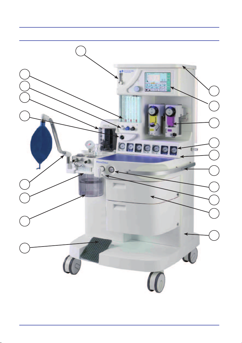
Figure 1 - BleaseSirius Anesthetic Machine
Page 23

Technical Description
Figure 1 Key
A Monitor shelf
B Ventilator
C Vaporizer
D Cylinder/pipeline gauges
E Pneumatic unit - (behind gauge panel)
F Handle
G Oxygen fl ush
H Common gas outlet (or option A.C.G.O.)
I Drawer
J Frame
K Brake Pedal
L Absorber
M Bag Arm Link Pipe
N Adjustable Bag Arm
O Main On/Off Switch
P Suction Controller
Q Flow Control Valves with Hypoxic Guard
R Flowblock Assembly
S Auxiliary Flowmeter
23
Page 24

Technical Description
1.2 Specifi cation
1.2.1 Machine Dimension
Height Max. Width Depth Average Weight
1486mm / 158.5” 705mm / 27.7” 747mm / 29” 110kg / 242.5lbs
1.2.2 Work Surface Dimensions
Height Area
854mm / 33.6” 98612.2mm2 / 152.8”
1.2.3 Monitor Shelf Dimensions
Height Area
1486mm/58.5” 175833mm2 / 272.54”
2
2
1.2.4 Maximum Loading
Monitor
Shelf
25kg/55.1lbs
evenly
distributed
Work
Surface
25kg/55.1lbs
evenly
distributed
Gross Loading = 250kg/551.1lbs
24
Bottom
Shelf
8kg/17.6lbs
evenly
distributed
Drawers
5kg/11.0lbs
evenly
distributed
Extended Work
Surface
15kg/33.0lbs
evenly distributed
(intermittent or
occasional loading
only).
Page 25

Technical Description
1.3 Pneumatics
1.3.1 Gas-Specifi c Color Specifi cations
Gas ISO ANSI
Oxygen White Green
Nitrous Oxide Blue Blue
MED AIR Black Yellow
1.3.2 Gas Supply Combinations
Max No. of Gases 3
Max No. of Cylinders 4
Max No. of Pipelines 3
Max No. of Gauges 7
Max Cylinder Size
(using PIV Index)
Large Cylinder Kit Max. 2
E
1.3.3 Common Gas Outlet
The common gas outlet is fi tted onto the front of the machine below the work
surface. It will accept a 22mm female or a 15mm male taper coupling.
25
Page 26

Technical Description
1.4 Technical/Performance Specifi cation
1.4.1 Controls
Oxygen fl ow 150ml/m to 10 l/m Simplex/ Cascade
Nitrous oxide fl ow 0ml/m to 12 l/m Simplex/Cascade
MED AIR fl ow 0ml/m to 15 l/m
Flowblock assembly accuracy ±5% measured value at 20ºC and
101.3 kPa/14.6 psi
Oxygen fl ush Non-locking 35 to 55 l/m
Vaporizers Accepts Selectatec
Hypoxic gases Minimum 21% oxygen/nitrous oxide
mixture allowed
1.4.2 Ventilator
A Blease700/900 ventilator is built
into the BleaseSirius.
1.4.3 Alarms / Indicators
Oxygen failure Audible alarm sounds for minimum
of 8 secs when oxygen pressure falls
below 30 psi.
1.4.4 Regulator Safety Valve Settings
Cylinder regulator 43 psi - 47 psi
Cylinder regulator relief valve > 75 psi
Machine gas piping design
rating
Secondary hypoxic regulators
Common gas outlet relief valve 3.25 psi - 3.95 psi
26
700 kPa/max. 101.5 psi/max
25-32 psi
25-35 psi
O
N
2
O2 0.5 Lpm fl ow
}
Page 27
Technical Description
1.4.5 Electrical
Voltage 100 / 230 V
Frequency 60 / 50 Hz
Power 1.2 / 1.0 kVa
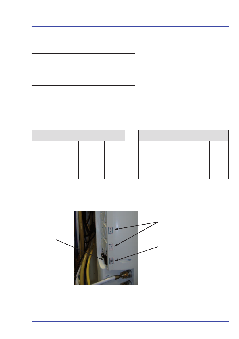
The auxiliary sockets are numbered 1 through 4, top to bottom and are rated
as in the following tables. If the machine has the switching sockets option,
sockets 3 and 4 will switch On and Off when the Main On/Off (Figure 1, Key
O) is switched On and Off, rather than with the Mains On/Off switch (Figure 2).
230V 110V
Socket
1 2A 3A 5A 1 - 4 2A 3A 4A
2 - 4 1A 2A 3.15A
1.4.5.1 Electrical Labeling
Mains ON/OFF
Outlet
Rating
switch
Breaker Fuse Socket
Figure 2 - Electrical Labeling
Outlet
Rating
Switched outlet label
Isolation transformer label
Breaker Fuse
27
Page 28

1.4.6 Supplies
O2, MED AIR, N2O pipeline Nominal pressure 400 kPa/58.0 psi,
Technical Description
minimum 275 kPa/39.8 psi, maximum
482 kPa/69.9 psi
Auxiliary pneumatic outlets MED AIR or O
zero fl ow. 80 l/m max. fl ow
Auxiliary Oxygen Outlet 0-15 lpm
1.4.7 Environmental
Operating Temperature 5ºC-40ºC (41ºF-104ºF)
oxygen cell operates to specifi cation
10ºC-40ºC (50ºF-104ºF)
Storage Temperature -20
cell removed
0ºC-50ºC (32ºF-122ºF) with oxygen
cell in place
Humidity 15-95% Non-condensing
- 400 kPa/58.0 psi at
2
o
C-60ºC (-4ºF-140ºF) with oxygen
28
Page 29

BleaseSirius
Anesthetic Machine
Chapter 2
Overview
29
Page 30

Overview
30
Page 31
Overview
2.1 Description of the Ventilator
2.1.1 Overview
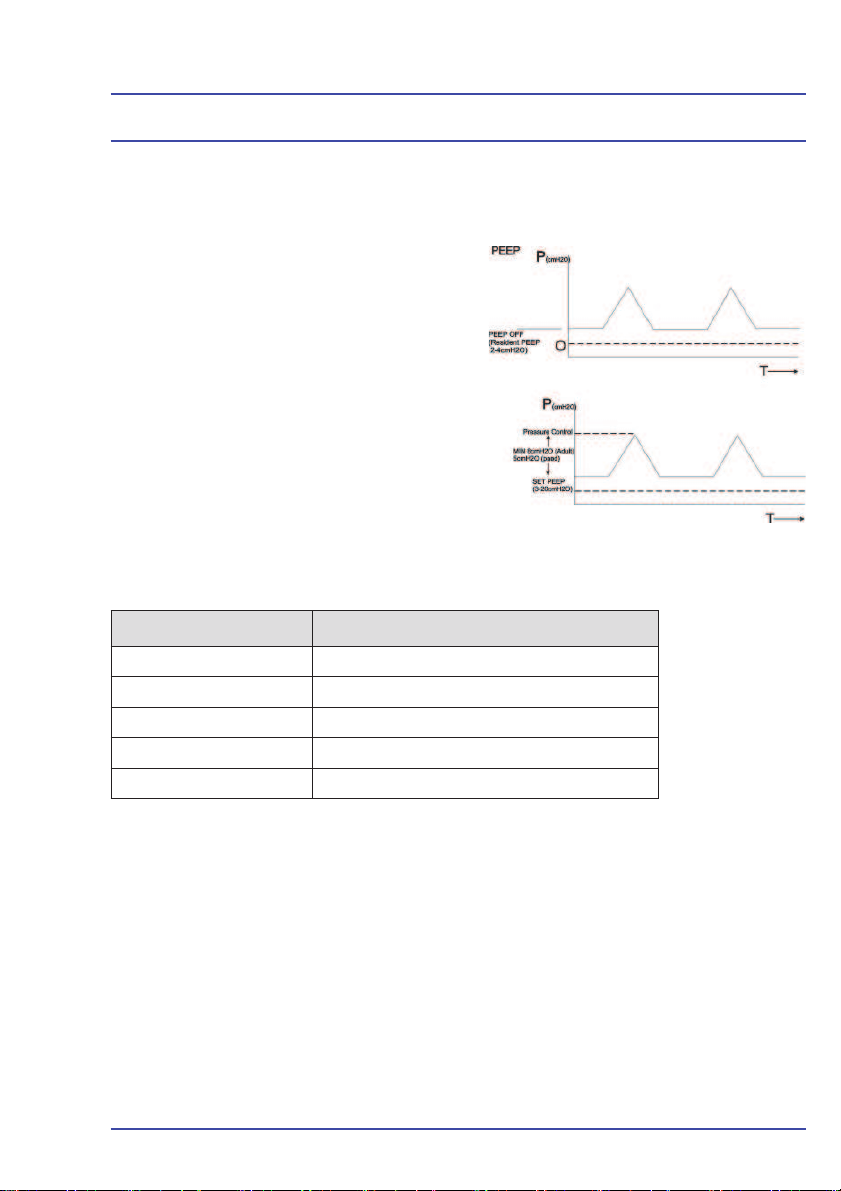
2.1.1.1 PEEP
The Blease700/900 series ventilator
continuously monitors and displays
the Positive End Expiratory Pressure
(PEEP). By default, a PEEP of
2 - 4 cmH
caused by the bellows assembly,
which is shown as OFF. A PEEP value
between 3 and 20 cmH2O can be set
from the panel, with an automatic alarm
of more than 25% above the set value.
A minimum difference of 8 cmH2O
in adult and 5 cmH2O in pediatric is
enforced between the set PEEP level
and the pressure controls shown below.
Mode Pressure Control
Volume Control Pressure Limit
Pressure Control Set Pressure
Pressure Support Support Pressure
SIMV-VC + PSV Support Pressure + Set Volume
SIMV-PC + PSV Support Pressure + Set Pressure
O is introduced to the circuit,
2
Figure 3 - PEEP Diagram
When the user changes a value such that it does not comply with the required
difference, the box surrounding the feature being adjusted and the value of
the feature causing limiting to be enforced is highlighted red. The value being
adjusted could either be the PEEP level or the relevant pressure control.
The user can then:
• Accept the value being adjusted, in which case, it will be set to the
nearest acceptable value.
• Adjust the value to a non-confl icting value.
If the user does not make the change before end of time allowed for adjustment,
the value will set to the nearest acceptable value.
31
Page 32

Overview
2.1.1.2 Trigger
The level of negative fl ow caused by the patient’s attempt to breathe before the
ventilator initiates fl ow to assist the patient with the spontaneous breath.
Range: 1 to 15 l/m all modes (SIMV + PSV and Pressure Support).
2.1.1.3 Support Pressure
Breathing circuit pressure level for assistance with patient’s spontaneous breath.
Range: 5 cmH
referenced).
O to 30 cmH2O SIMV-PC + PSV and Pressure Support (PEEP
2
2.1.1.4 Fresh Gas Compensation
Fresh gas can be compensated for and displayed on screen.
2.1.1.5 Oxygen
A fuel cell sensor can be connected to allow monitoring of 0% to 110% O
alarms of 18% to 110%. The sensor can be calibrated.
, with
2
2.1.1.6 Tidal Volume
Volume to be delivered by the ventilator in each breath.
Range: 20 ml to 1500 ml all modes.
2.1.1.7 Minute Volume
Measured volume delivered by the ventilator per minute.
Range: 0.3 l/m to 25 l/m all modes.
2.1.1.8 Expired Tidal volume
Expired tidal volume is measured by the sensor in the breathing circuit, in either
mechanical ventilator spontaneous breathing mode. The measured value is
displayed in the tidal volume window.
2.1.1.9 BPM (Frequency Control)
The mechanical frequency of the ventilator in breaths per minute (BPM).
Range: 2 bpm to 99 bpm all modes.
32
Page 33

Overview
2.1.1.10 I:E Ratio
The ratio of the inspiratory time to the expiratory time.
Range: 2.0:1 to 1:5.0, all modes in steps of 0.1.
2.1.1.11 Pressure Limit
The breathing system maximum pressure limit.
Range: 10 cmH
10 cmH2O to 50 cmH2O Adult.
O to 50 cmH2O Pediatric.
2
2.1.1.12 Peak Pressure
Range: 0 cmH
O to 100 cmH2O
2
2.1.1.13 Mean Pressure
Range: 0 cmH
O to 100 cmH2O
2
2.1.1.14 Compliance
System compliance in ml/cmH
Patient compliance in ml/cmH2O
O
2
2.1.1.15 Volume Measurement
Accuracy of delivered gas at 25ºC 101.3 kPa/14.6 psi (volume mode)
= ±10% or ± 10 ml from 50 ml to 1 liter
(whichever is greater)
Volume monitoring accuracy = ± 10% or ± 10 ml (whichever is greater)
Controlled Patient Pressure = ± 10% or ± 2 cmH
Monitored Patient Pressure = ± 5% or 1 cmH2O (whichever is greater)
O (whichever is greater)
2
Delivered PEEP = ±1.5 cmH2O from 4 to 20 cmH2O (whichever is greater)
Fresh Gas Flow = ± 10% or ± 200 ml from 300 ml to 15 liters (whichever is
greater)
2.1.1.16 Oxygen Measurement
Oxygen Concentration accuracy = 3%.
Drift < 1% over 8 hours at constant temperature.
Response time < 30 seconds for 90% change.
33
Page 34

Overview
2.2 Pre-use Test
2.2.1 Fresh Gas
Fresh gas (FG) fl ow adds to the delivered Tidal Volume (TV) during the
inspiratory period. To compensate, the delivered volume must be reduced.
The formula for this reduction is:
Effective TV = TV - TV due to FG
TVE =TV - ((FG fl ow rate (mL)/60)* Inspired time (sec))
TVE = TV - TV
For example, let
FG fl ow rate = 5LPM, TV = 600mL, Frequency = 10BPM, I:E = 1:20
Inspired time = * = 2 Sec
TVfg = * 2 = 83 1/3 = 167ml
Therefore,
Effective TV = 600 - 167 = 433mL
5000
60
FG
1
60
10
3
2.2.2 Compliance
Compression of gas in the dead space within the breathing system reduces the
tidal volume delivered to the patient. In an ideal ventilator, the Set TV would
be the volume of gas that is delivered to the patient’s lungs. This cannot be
achieved because the anatomy of the patient is unknown. However, the Set
TV can be accurately delivered from the catheter mount, thus reducing Set TV
errors to a minimum.
To calculate the effect of breathing system compliance on
the delivered TV, it is necessary to measure the capacity or
compliance (Cs) of the system. This can only be done as part
of a pre-use check procedure.
34
Page 35

Overview
1. Switch the unit ON. The compliance menu will be displayed.
The patient airway fl ow sensor head must be in the patient circuit
in order to carry out compliance compensation.
2. Select Yes to Compliance Compensation and follow the instructions
on screen instructions
The ventilator delivers a breath of known volume to the breathing circuit, records
the pressure (cmH
O) achieved and verifi es that a leak is not present.
2
3. The dead space is calculated as follows:
Volume (mL)
= dead space compliance (C
Pressure (cmH20)
)
3
This value is retained in memory until the ventilator is switched off or retested.
4. When the ventilator is set to use on a patient and when the
ventilation is stable, the total compliance of system and patient
(Ct) is measured. The TV can then be increased to compensate for
the volume lost due to compression within the breathing system.
The increase in tidal volume is calculated by the formula:
C
Set TV * (
1 + ) = new TV (mL)
s
C
C
-
t
s
For example:
A system test measurement at a TV of 200 ml gave a pressure rise of 25 cmH
C
200mL
=
s
25cmH2O
= 8
O.
2
Running the ventilator on a patient with a set 500ml TV gave a peak pressure
of 20cmH
O.
2
35
Page 36

Overview
To calculate the increase in TV:
C
The 735ml is the actual ventilator output into the breathing circuit to give
500ml at the catheter mount. The value must be recalculated every time volume
controlled ventilation starts.
500mL
=
t
20cmH2O
= 25
new TV = 500 * (
2.2.3 Compensation
Mode Compliance Fresh Gas
Volume Control
Pressure Support
SIMV-VC + PSV
SIMV-PC + PSV
Pressure Control
1 + ) = 735mL
25 88-
P P
O P
P P
O P
O P
36
Page 37

Overview
2.2.4 Mode Dependant Features
PRESSURE
V O L U M E
CONTROL
SIGH PAUSE
P P O O
SUPPORT
TRIGGER
PRESSURE
SUPPORT
PRESSURE
BPM
Set
VOL/
FLOW
Meas/
Set
I:E
Set
PRESSURE
LIMIT
Pressure
Limit
PR ESS U RE
SUPPORT
SIMV-VC +
PSV
SIMV-PC +
PSV
PR ESS U RE
CONTROL
O O
O P
O O
ALWAYS ALWAYS Meas Meas Meas
ALWAYS ALWAYS
ALWAYS ALWAYS
O O O O
Meas/
Set
Meas/
Set
Set
Meas/
Set
O
IINSP
FLOW
Meas/
Set
Meas/
Set
Set
Pressure
Limit
Pressure
Limit
Ptot
Set
Pressure
37
Page 38

Overview
38
Figure 4 - Ventilator Schematic
Page 39
Overview
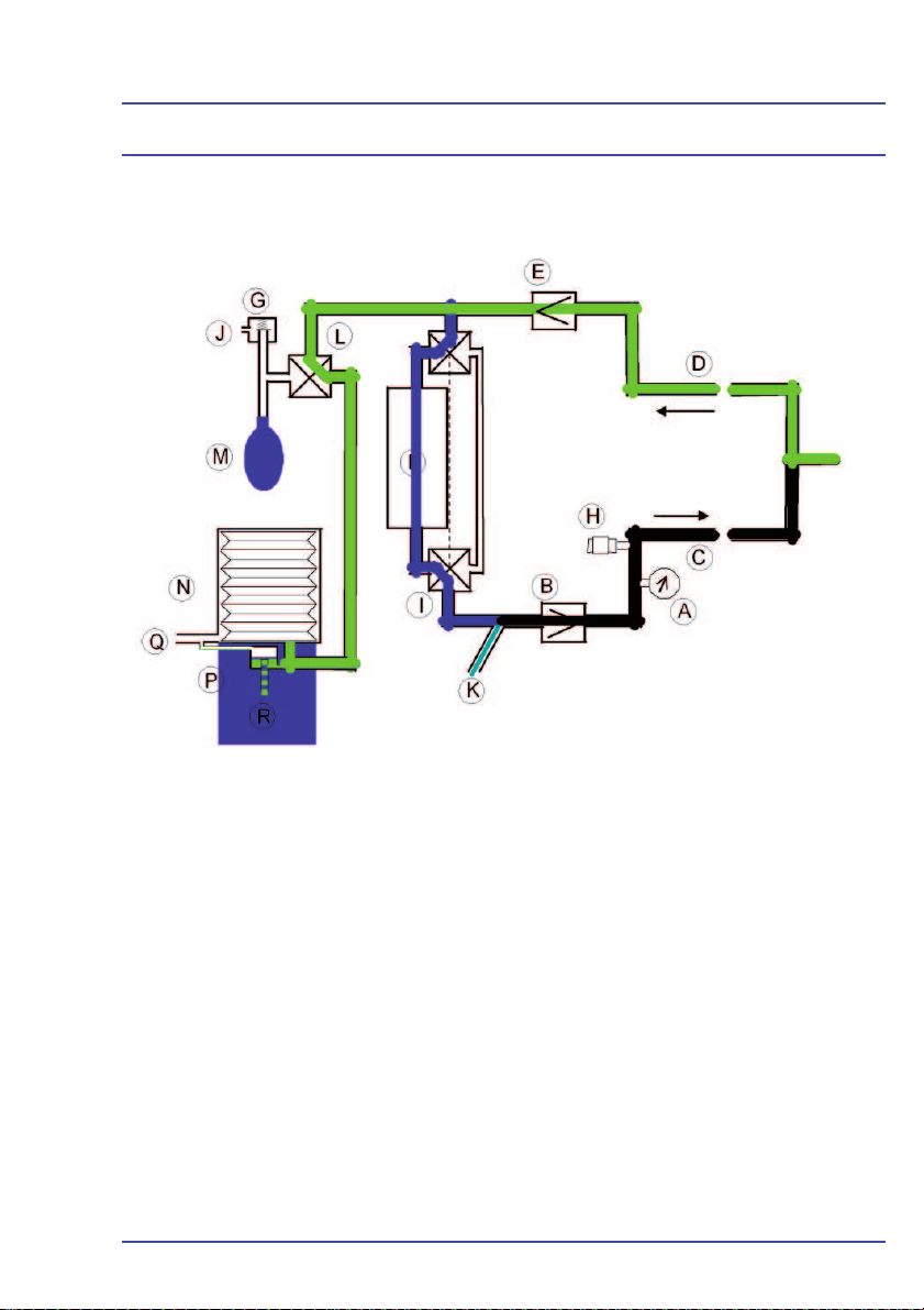
A Manometer
B Inspiratory Non-return Valve
C Patient Inspiratory Connector
D Patient Expiratory Connector
E Expiratory Non-return Valve
F Canister(s)
G APL Valve
H Oxygen Sensor Port
I Bypass Switch
Figure 5 - Absorber Pneumatic Schematic
J APL Exhaust Valve
K Fresh Gas Port
L Bag/Vent Valve
M Bag Port
N Bellows
P Pop-Off Valve
Q Ventilator Drive Gas
R Pop-Off Exhaust
39
Page 40

Overview
M
S
O
J
A B
T
U
P
Q
C
D
A Air Pipeline
B Air Cylinder Yoke
C N
D N
E O
F O
O Pipeline
2
O Cylinder Yoke
2
Pipeline
2
Cylinder Yoke
2
G Reservoir
H Auxiliary Flowmeter
I O2 High Pressure Outlet
J Air Takeover Valve
K O
Failure Alarm Whistle
2
L O2 Failure Alarm Valve
M On/Off Switch
V
M
K
L
FE
Y
Z
W
R
G
H
I
X
N
N Vent Supply
O Air Secondary Regulator
P N
O Secondary Regulator
2
Q Oxygen Secondary Regulator
R Oxygen Flush
S Air Flowmeter
T N
O Flowmeter
2
U Hypoxic Protection Link System
V Oxygen Flowmeter
W Pressure Relief Valve
X CGO
Y Seletatec Back Bar
Z Fresh Gas Flow Sensor
40
Figure 6 - Pneumatic Circuit
Page 41

Overview
2.3 Principles of Operation
For active inspiration, the fl ow control valve is opened to provide a specifi c gas
fl ow into the bellows assembly. Simultaneously, the expiratory solenoid closes
and pressure is generated in the bellows assembly producing an inspiratory
fl ow to the patient.
The fl ow and pressure are measured and monitored by the microprocessor
feedback system.
Expiration occurs when the fl ow control valve is closed and the expiratory
solenoid opens and releases the gas from the bellows assembly.
In Pressure Control Mode, the set pressure is achieved during inspiration
and maintained at that level by allowing a controlled bypass through the
expiratory valve. This allows the required pressure level to be maintained while
compensating for any fresh gas fl ow into the patient circuit.
For expiration, the expiratory solenoid is opened which releases the gas from
the bellows assembly.
During all modes of ventilation, an autozero is periodically applied to the fl ow
sensors just prior to a breath being delivered. At this point, there is no fl ow
through the sensors, which ensures that the measured values are maintained
as accurately as possible regardless of environmental variations.
A safety valve is present in the drive pressure exhaust
75 cmH2O. Its function is to protect the patient against pressures exceeding 75 cmH2O ± 2 cmH2O by relieving the drive
pressure on the bellows.
NEEP is not supported by this machine but patient generated pressures may be measured to - 10 cmH2O, at which
point an alarm will sound.
41
Page 42

Notes
42
Page 43

BleaseSirius
Anesthetic Machine
Chapter 3
Planned Maintenance
43
Page 44

Planned Maintenance
44
Page 45
Planned Maintenance
3.1 Planned Maintenance
Only authorized technical engineers should service the machine, since they
have the appropriate training and qualifi cations in the use of high-pressure
medical devices. Servicing should take place in a clean and controlled
environment taking particular care to prevent contaminants entering the unit
while disassembled.
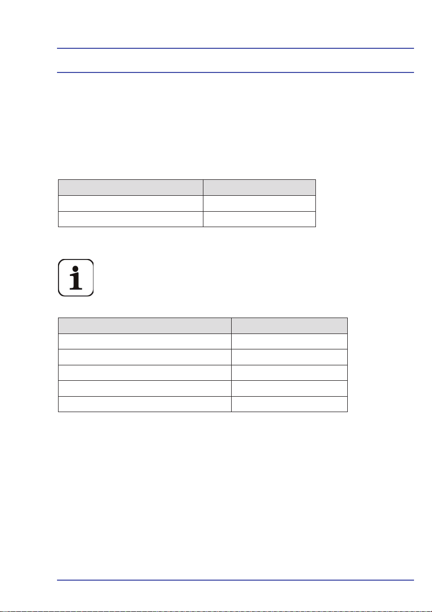
Service Kits Part Number
Annual Service Kit 14000511
*Four-Year Service Kit 14000512
* Includes all parts required for units with four cylinder yokes installed.
All parts included in PN 14000512 are not required for all
BleaseSirius machines. You can order idividual parts instead of
ordering PN 14000512.
Four-Year PM Kit Contents Part Number
*Annual PM Kit 14000511
*Battery 80300025
**Regulator Pressure Relief Valve 019-0831-00
***Filter 53700027
***O-ring 51150283
* Required for every machine
**One kit required for each cylinder yoke installed on the machine.
***Required for machines sold before February 2009.
45
Page 46

Planned Maintenance
• Bodocs Seals
• Backbar Seals
• Absorber Stop
+ O2 Blanking
Plug
• Backbar Dzus
Springs
• AGSS Probe
Seal
• AGSS Float
Seal
• Pipeline Filter
• Pipeline ‘O’ Ring
• Bellows Base/
Cover
• Ped Bellows
• Bellows Base/
Pop off
• Absorber Upper
Seal
• Absorber ‘O’
Rings for Insp/
Exp + APL
• Pop off Valve
• Absorber Gauge
• Absorber
Control Seal
• Absorber
Bottom Canister
Figure 7 - BleaseSirius Annual Planned Maintenance Kit
PN 14000511
46
Page 47

Planned Maintenance
• Cylinder
Regulator
Service Kit
• ‘O’ Ring for
Filter
• Battery
Figure 8 - BleaseSirius Four Year Planned Maintenance Kit
PN 14000512
Note:
Includes annual
kit, PN 14000511
47
Page 48

Planned Maintenance
3.2 Routine Maintenance and Service Check.
3.2.1 Fitting Planned Maintenance Kit PN 14000511
Bodoc Seals (1), Backbar Seals (2) and O2 Probe ‘O’ Ring (3)
are duplicated. The duplicated set is to be placed in one of the
drawers for the user to replace if one is damaged or fails test
during use.
3.2.2 Bodoc Seals
1. Remove cylinders from the yokes, then remove the old Bodoc Seal
and replace with new ones.
2. Refi t the cylinder.
3.2.3 Backbar Seals
1. Remove vaporizers from the Selectatec backbar then remove all
four seals.
2. Replace with new ones.
3.2.4 Backbar Dzus Springs
1. Remove the two Dzus Spring assemblies by undoing the two
screws (in the diagonal corners of the plate). Lift the place up,
taking care not to drop the index pin. The index pin must be fi tted
to the new Dzus Spring assembly before fi tting new item.
2. Refi t the vaporizers and check that they locate and lock on the
backbar currently.
3.2.5 Absorber Stop/’O’ Ring
1. Remove the ‘O’ Ring from the absorber blanking plugs and
absorber stop, then replace them. (The new cell is supplied with
‘O’ ring fi tted.)
3.2.6 Pipeline Fitting and ‘O’ Ring
1. Disconnect pipelines from their supply. Disconnect the pipeline
connection from the BleaseSirius.
2. Unscrew the two small grub screws until the main body of the
connection is free to rotate.
3. Unscrew the connector, the fi lter and ‘O’ Ring can now be changed.
48
Page 49

Planned Maintenance
4. Refi t the outer part of the connector and tighten the two small grub
screws.
5. Repeat for all three pipelines.
6. Note each gas type has a unique fi tting and can not be incorrectly
mixed.
7. Refi t the pipeline and check for leaks.
Figure 9 - Pipeline Fitting & ‘O’ Ring
49
Page 50

Planned Maintenance
3.3 AGSS Probe and Float for Spacelabs AGSS
PN 14200018, (if Fitted)
The AGSS is not available in the U. S.)
1. Disconnect electrical supply to BleaseSirius
2. Remove the bellows assembly by sliding the absorber forward until
the bellows connections become free, then
remove the two thumb wheels at the front of
the bellows. The bellows assembly can now
be lifted clear of the locating pins at the rear of
the bellows assembly.
3. Working through the apparatus below the
bellows assembly.
4. The AGSS probe can be pulled out of the top of
the AGSS unit.
5. Remove the ‘O’ Ring and replace with the new
part.
6. Disconnect the 30mm connector from the
side of the AGSS unit, (located approximately
100mm down the AGSS unit).
7. The AGSS unit will now pull off its V mounting
bracket and can be removed through the
apparatus.
8. Hold the lower black part of the body (where
the 30mm connector is) and unscrew the top
black part (with the windows).
9. Clean the fi lter.
10. Remove the top ‘O’ Ring slide the green fl oat
off the central stem and remove the bottom
‘O’ Ring.
11. Replace the bottom ‘O’ Ring.
12. Refi t the fl oat (make sure it is the correct way
up) then replace the top ‘O’ Ring.
13. Reassemble the fi tted/window on top, screw
onto the lower sections.
14. Place the AGSS unit back onto its V bracket.
15. Refi t the 30mm connector and the AGSS probe.
“O’ Ring
“O’ Ring
Figure 10 - AGSS
50
Page 51

Planned Maintenance
3.4 Bellows Base/Canister
1. Remove the bellows cover (bayonet fi tting), then replace the
bellows base/canister ‘O’ Ring.
2. Remove the bellows by gently pulling the lower convolution of the
retaining ring.
3. Remove the pop-off valve.
4. Replace the bellows base pop-off valve “O” ring.
3.5 Pop-off Valve
Figure 11 - Pop-off Valve
1. Replace Pop-off valve in bellows base.
2. Refi t bellows by gently pulling the lower convolution over the ring
in the bellows base.
3. Replace the bellows outer cover.
51
Page 52

Planned Maintenance
A
B
C
A - Cover
B - Bellows
C - Pop-off valve
D - Valve seat
E - Fixing screws
F - Bellows base
G - O-ring
52
G
D
E
F
Figure 12 - Bellows Assembly
Page 53

Planned Maintenance
3.6 Absorber
3.6.1 Valve Covers
When removing or refi tting any of these valves, it is important to
ensure the metal valve disk and seat are not damaged.
1. Remove the expiratory valve by twisting the clear plastic valve cover.
2. Replace the ‘O’ Ring seal on the valve cover.
3. Replace the expiratory valve on the absorber.
4. Remove the inspiratory valve cover.
5. Replace the ‘O’ ring seal.
6. Replace the valve cover.
7. Remove the APL valve.
8. Replace the ‘O’ ring seal.
9. Replace the APL valve.
3.6.2 Manometer
1. Remove the manometer gauge by pressing the quick release lever at the
base of the gauge.
2. Replace the ‘O’ ring seal.
3. Refi t the gauge.
3.6.3 Canister Seals
The outer canister seal is a bayonet fi tting.
1. Remove the soda lime canister.
2. The outer canister seal is located on the base of the absorber in the
groove.
3. Replace the outer canister seal.
4. The upper canister seal is fi tted to a lip inside the bottom absorber
molding.
5. Replace the upper seal.
6. The central seal is laid on top of the lower inner canister before the upper
canister is fi tted.
7. Install the canister assembly onto the bottom of the Absorber.
53
Page 54

Planned Maintenance
3.6.4 Fitting 4 Year Planned Maintenance Kit, PN 14000512
The recommended service intervals for the following are every 4 years. The
following procedure outlines the steps taken to replace the parts included in the
service kit 14200512.
3.6.5 Ventilator Filter
3.6.5.1 Two Valve Version Only (on units before Feb 2009)
1. Ensure all gas supplies are disconnected.
2. See Section 5.1 for removal of top surface and front cover.
3. Once the front cover is removed, you can access the 6 screws that secure
the top of the ventilator casing.
4. The front display panel will hinge forward a little. This will allow the top
cover to be hinged back.
5. The fi ller cover is in the inlet manifold which can be seen from the front
of the unit.
6. Remove the cover.
7. The fi lter can then be
unscrewed.
8. Replace the fi lter and cover
and make sure the new ‘O’
ring is fi tted.
9. Replace the screws in the
top cover and front display
panel.
10. Reconnect the O
pipeline
2
only and turn on the system.
11. Check that there are no
Figure 13 - Pneumatic Module
leaks.
12. Turn the systems OFF.
13. Fit the front cover and top surface.
3.6.5.1 Valve Block on units after Feb 2009
Due to major enhancements in the inlet fi ltration methods, a valve block fi lter is
no longer required and, therefore, is not fi tted.
54
Page 55

Planned Maintenance
3.6.6 Cylinder Regulator Pressure Relief Valve, PN 019-0831-00
1. Remove all cylinders.
2. Remove the large back panel.
3. Fit a service kit to each of the regulators.
Disassembly
1. Remove and discard relief valve by turning counter-clockwise using a
15/16” spanner or socket.
Assembly
1. Fit new relief valve and ‘O’ ring.
2. Reset the pressure as required. See ‘ADJUSTMENT’ below.
Adjustment
Turn the adjusting screw clockwise to increase and counterclockwise to
decrease outlet pressure setting. To reduce pressure, fi rst reduce to a
pressure less than that desired, then increase to the desired outlet pressure.
Turn the adjusting screw using a 1/8-inch hex key.
Once 45 psi setting has been achieved, secure the locknut.
55
Page 56

Planned Maintenance
3.7 CLEANING
Cleaning of external surfaces is possible using water or isopropyl alcohol.
Cleaning of internal surfaces and parts should not be required and is not
recommended.
This product is intended for use in medical compressed gas
systems only. Do not use this product where pressures and
temperatures can exceed those listed under Technical Data.
DO NOT use any lubricants that are not compatible with oxygen or medical gases. The use of lubricants not compatible
with oxygen may pose a risk of fi re or explosion.
Open the cylinder valve slowly to prevent the risk of fi re or explosion due to
oxygen pressure shocks. The relief valve is a safety device and must only be
removed for servicing. When servicing is complete, a new relief valve must be
fi tted. Do not attempt to adjust or tamper with the relief valve.
56
Page 57

Adjusting Screw
Spring
Planned Maintenance
Locknut
Bonnet
Slip Ring
Seal Ring
Body
Mounting Spacer
Upper Spring Rest
Diaphragm Assembly
Actuator Assembly
Valve Cartridge
‘O’ Ring
Relief Valve
Figure 14 - Primary Regulator
57
Page 58

Notes
58
Page 59

BleaseSirius
Anesthetic Machine
Chapter 4
System Checks
59
Page 60

System Checks
60
Page 61

System Checks
4.1 Overview
This chapter explains the systems checks that must be used on all BleaseSirius
anesthetic machines whenever any of the following procedures has been
performed:
• Installation
• Planned Maintenance (should be performed annually)
• Service
• Repair
Use the service check sheet, shown on page 64, to record the results.
4.2 Tools and Test Equipment Required
1. 2 mm, 2.5 mm, 3 mm, 4 mm, 1/8 inch Allen key
2. 13 mm wrench
3. Adjustable crescent wrench
4. Pressure measuring device (able to read 0 – 100 psi)
5. Pressure measuring device (able to read 0 – 100 cmH
6. Flow measuring device (able to read 0 – 100 L/min)
7. Flow measuring device (able to read 20 – 1000 ml)
8. Oxygen analyzer
9. Pressure Gauge (able to read 0 – 200 mmHg)
10. Copy of the BleaseSirius Checkout Sheet (See page 64). You can use a
print copy (073-0301-00) or an electronic copy (073-0321-00).
O)
2
Contact Technical Support at
advsupport@spacelabs.com to request an
electronic copy of the BleaseSirius Checkout Sheet.
61
Page 62

System Checks
Parts Required
Description Part Number Quantity
WHITE O2 DRV HOSE O2 NIST-UK
MINISCHRAEDER 0.32M
BLACK AIR DRIVEHOSE AIR NIST-UK
MINISCHR. 0.32M
GREEN O2 DRIVE HOSE O2 DISS-US DISS
0.32M
CONNECTOR, 22MM FEMALE TO BARB,
STAINLESS STEEL
9/16 O CLIP STD GAUGE ST2161 3
2 LITRE RE-BREATHING BAG ST2111 2
Patient Flow Sensor 10110090 2
Pediatric Flow Sensor 376-0561-00 2
22mm female – female connector 54100065 1
Clear smooth bore hose 166-7060-00 1
Siemens test lung 54100057 2
17mm male – 22mm female connector 12500055 1
6mm tubing (green) 53500030 100
C.G.O. ADAPTOR SK2226 3
6mm plug 54200151 5
BACKBAR VALVE TEST KIT 930210 1
22MM MALE /22MM MALE CONN ST4710 3
PATIENT CIRCUIT ASSEMBLY M1050-4 1
ANST,HYTREL TUBING,22MM
ID,110CM,REUSABLE
Fomblin Lubricant ST7014 1
Programming Cable 12600015 1
Pressure Sampling Tee 10500003 2
Dowty Seal 50300035 5
Snoop ST8026 1
10700007 1
10700008 1
10700009 1
376-0559-00 3
709-0488-00 1
62
Page 63

System Checks
Description Part Number Quantity
Pipeline Leak Test Valve, O2 DISS 010-1981-00 1
Pipeline Leak Test Valve, N2O DISS 010-1982-00 1
Pipeline Leak Test Valve, AIR DISS 010-1983-00 1
Note: Use PNs 010-1981-00, 010-1982-00 and 010-1983-00 for the Reverse DISS
Pipeline Leak Test.
Pipeline Leak Test Valve, O2 NIST 010-1984-00 1
Pipeline Leak Test Valve, N2O NIST 010-1985-00 1
Pipeline Leak Test Valve, AIR NIST 010-1986-00 1
Pipeline Leak Test Valve, O2 SIS 010-1987-00 1
Pipeline Leak Test Valve, N2O SIS 010-1988-00 1
Pipeline Leak Test Valve, AIR SIS 010-1989-00 1
63
Page 64

System Checks
Visual Ins
p
ection Hi
g
h Pressure Outlets
(
= or > 80LPM
)
Ventilator
Descri
p
tion Pass Fail N/A Descri
p
tion Pass Fail N/A Descri
p
tion Pass Fail N/A
C
y
linder Yokes O2 Shraeder
(
if fitted
)
Com
p
liance test
Pi
p
eline Inlets O2 diss
(
if fitted
)
S
y
stems check
Pi
p
eline Hoses Air Shraeder
(
if fitted
)
CALBK: flow control cal
Absorber Rods H
yp
oxic Guard/Flow Control Accurac
y
CALBK: ins
p
irator
y
valve cal
H
p
Outlet
(
if fitted
)
Descri
p
tion Pass Fail N/A CALBK: block and
p
ressure zeros
Backbar Flowmeter backli
g
ht
(
non-EFM
)
T
ouchscreen calibration
O2 Flush Ass
y
Min. O2 flow
(
130 - 170ml
)
Fresh
g
as calibration
Common Gas Outlet N2O = 1LPM
(
O2 = 21 - 30 %
)
VTI = 250 ±25ML
Flowmeter Ass
y
/ Control Knobs N2O = 6LPM
(
O2 = 21 - 30 %
)
VTI = 500 ±50ML
Drawers N2O = 12LPM
(
O2 = 21 - 35 %
)
VTI = 750 ±75ML
Castors O2 = 3LPM
(
O2 = 21 - 30 %
)
PEEP = 10 ±1.5cmH2O
Pi
p
eline Leak Test O2 = 1.5LPM
(
O2 = 21 - 30 %
)
Pressure = 10 ±2cmH2O
Descri
p
tion Pass Fail N/A O2 = 0.4LPM
(
O2 = 21 - 30 %
)
Pressure = 30 ±3cmH2O
O2 O2 & N2O = 3LPM
(
O2 = 47 - 53 %
)
Pressure Hi
g
h Alarm
N2O
(
if fitted
)
O2 & N2O = 6LPM
(
O2 = 47 - 53 %
)
Alarms
Air
(
if fitted
)
O2 & Air = 3LPM
(
O2 = 57 - 63 %
)
Descri
p
tion Pass Fail N/A
C
y
linder Leak Test O2 & Air = 6LPM
(
O2 = 57 - 63 %
)
A
p
nea
Descri
p
tion Pass Fail N/A Backbar Sustained
p
ressure
O2
(
if fitted
)
Descri
p
tion Pass Fail N/A Low
g
as
p
ressure
2nd O2
(
if fitted
)
Build u
p (
150mmH
g
in 7 sec
)
Pressure low
N2O
(
if fitted
)
T1
(
left side
)
O2 su
pp
l
y
fail
2nd N2O
(
if fitted
)
T1
(
ri
g
ht side
)
Pressure Limit
Air
(
if fitted
)
T2
(
left side
)
Minute vol. Low
C
y
linder Out
p
ut Test
(
45 ± 2PSI
)
T2
(
ri
g
ht side
)
Minute vol. Hi
g
h
Descri
p
tion Pass Fail N/A Common Gas Outlet Ox
yg
en low
O2
(
if fitted
)
Descri
p
tion Pass Fail N/A Ox
yg
en hi
g
h
2nd O2
(
if fitted
)
O2 flush
(
35 - 55LPM
)
O2 sensor error
N2O
(
if fitted
)
PRV
(
3.25 - 3.95PSI
)
Mains fail
2nd N2O
(
if fitted
)
Suction Absorber not fitted
Air
(
if fitted
)
Descri
p
tion Pass Fail N/A Va
p
orizer Concentration
(
if fitted
)
On/Off Switch Gas Cut Off Off
p
osition Descri
p
tion Pass Fail N/A
Descri
p
tion Pass Fail N/A Full
p
osition Va
p
s/n:
Switch "Off" no flow available Re
g p
osition Va
p
s/n:
Switch "On" flow available Absorber Va
p
s/n:
Switch "Off" flow dro
p
s to "0" Descri
p
tion Pass Fail N/A Va
p
s/n:
Switch "On" flow restored Ex
p
irator
y
leak test
(
<60ml/min
)
Va
p
s/n:
Ox
yg
en Su
pp
l
y
Failure Ins
p
irator
y
leak test
(
<60ml/min
)
Electrical Safet
y
Descri
p
tion Pass Fail N/A APL = 65
(
59 - 71cmH2O
)
Descri
p
tion Pass Fail N/A
Alarm sounds for 8 sec APL = 30
(
24 - 36cmH2O
)
<300µA(120/100Vac)/<500µA(220/240Vac)
N2O dro
p
s to "0"
(
if fitted
)
APL = MIN
(
<5cmH2O
)
<0.2ё
Air available
(
if fitted
)
BleaseSirius Service Checkout, PN 073-0301-00, Rev. C
Hospital: .
Address: .
........
City:.ST:.
.......
Contact:..PhoneNumber:.
SiriusSN: .
FrontPanelSW:.
BavControlerSW:.
Model#:.
AbsorberSN:.
Customer
PrintName:.Signature: .
Date: .
Representative
PrintName:.Signature: .
Date: .
64
Figure 15 - BleaseSirius Checkout Sheet (PN 073-0301-00 Rev. C)
Page 65

System Checks
4.3 Visual Inspection
Check that the following components are free of damage and are securely
mounted to the machine and/or fi ttings.
1. Cylinder Yokes
Verify the yoke block, index pins and bridges are free of damage and that the
tee screw freely threads into the yoke bridge.
2. Pipeline Inlets
Verify that the pipeline inlets are free of damage and inspect the threads for
damage as well. Connect pipeline hoses to each inlet and ensure that the hoses
connect freely.
3. Pipeline Hoses
Verify that pipeline hoses are free of deterioration and damage. Connect both
ends of the hoses and pull them to check for a secure connection.
4. Absorber Rods
Verify that the rods are free of damage, secure and not bent.
5. High Pressure Outlet (if fi tted)
Verify that the High pressure outlets are free of damage. Connect the proper
hose and check for a secure connection.
6. Backbar
Verify the backbar and backbar valves are free of damage. Check that the
o-rings on the valves are free of damage.
7. Oxygen Flush Assembly
Verify that the assembly is free of damage. Push the fl ush button and ensure it
goes in and comes out smoothly.
8. Common Gas Outlet
Verify that the common gas outlet is free of damage. Pull on the outlet and
ensure it is secured to the frame.
65
Page 66

System Checks
9. Flowmeter Assembly & Control Knobs
Verify that the fl owmeter assembly and knobs are free of damage. Turn the
knobs on and off to check for a smooth operation.
10. Drawers
Verify that the drawer(s) are free of damage. Open and close the drawers to
check for a smooth operation.
11. Castors
Verify that the castors are free of damage. Check that when the castors brakes
are not engaged, the machine can move freely in any direction. Listen for noise.
When the brake is engaged, ensure that the machine cannot be moved.
4.4 Pipeline Leak Test
1. Ensure that the On/Off switch is in the “OFF” position.
2. Ensure that all fl ow control valves are closed.
3. Ensure that no cylinders are fi tted to the machine.
4. If fi tted, disconnect all pipeline hoses connected to the pipeline inlets
coming from the hospital supply. Disconnect the hospital supply before
you perform this step.
5. Connect the pipeline test shut-off valve to the appropriate pipeline inlet for
the gas being tested (O
position.
/ N2O / AIR) and ensure the valve is in the “OFF”
2
66
Figure 16 - Connect the Pipeline Test Shut-off Valve
Page 67

System Checks
6. Connect the appropriate pipeline hose to the pipeline test shut-off valve
assembly, and then connect it to the hospital supply.
7. Turn the pipeline test shut-off valve “ON” to allow fl ow.
8. Verify that the appropriate gauge registers.
9. Wait 15 seconds for the system to pressurize and shut the pipeline test
shut-off valve off.
10. Disconnect the pipeline hose from the hospital supply and verify that the
appropriate digital gauge is still registering.
11. Verify that the pipeline gauge does not fall 50 kPa, half of a division in
three minutes.
Figure 17 - N
O Pipeline Gauge
2
12. If the leak test is passed, disconnect the pipeline test shut-off valve from
the machine and verify that the pipeline gauges value drops to zero.
13. Repeat steps 5-12 for all additional pipelines fi tted.
67
Page 68

System Checks
4.5 Cylinder Leak Test
1. Ensure that all fl ow control valves are turned off.
2. Ensure that the power switch is in the “OFF” position.
3. Ensure that no pipeline supply is connected to the pipeline inlets.
4. Fit a full O
5. Turn on the cylinder and ensure that the appropriate gauge registers
correct.
6. Close the cylinder and verify that the gauge does not drop more than
150 psi (345 kPa) over two minutes.
7. Remove the cylinder and verify the gauge reads zero.
8. Repeat steps 1-7, if two O
9. Repeat steps 1-7, if an air yoke is fi tted. Use a full air cylinder (at least
1000 psi).
10. Fit a full N
11. Turn on the cylinder and ensure the appropriate gauge registers correct.
12. Close the cylinder and verify that the gauge does not drop more than 150
psi (345kPa) over two minutes.
13. Remove the N
14. Repeat steps 10-13, if two N2O yokes are fi tted.
cylinder (at least 1000 psi) to the O2 yoke.
2
yokes are fi tted.
2
O cylinder (at least 700 psi) to the N2O yoke.
2
O cylinder and verify the gauge reads zero.
2
4.6 Regulator Output Test
1. Remove the lower inspection cover.
2. Ensure that the power switch is in the “OFF” position.
3. Fit a full cylinder to the yoke of the appropriate regulator being tested.
/ Air: at least 1000 psi and N2O: at least 700 psi).
(O
2
68
Page 69

System Checks
4. Disconnect the 6 mm plug from the regulator test point, then connect a
pressure measuring device to the test point.
Figure 18 - Connect Pressure
Measuring Device
5. Turn the cylinder on.
6. Turn the switch to the “ON” position and set a fl ow of 1 L/min on the fl ow
control valve for the appropriate gas being tested.
7. Verify that the pressure measuring device reads between 45 ± 2 psi.
8. If the reading is out of spec, loosen the nut on the regulator being tested
using a 13 mm wrench. Adjust the set screw using a 1/8 inch Allen key to
set the regulator to 45 ± 0.5 psi. Once achieved, secure the nut.
Figure 19 - Regulator Nut and Set Crew Locations
9. Repeat steps 3-8 for all regulators. (Note: When testing outputs or making
adjustments on N2O regulators, ensure that an O2 supply is connected to
the O2 pipeline inlet.)
69
Page 70

System Checks
4.7 On/Off Switch Gas Cut Off Test
1. Ensure that the power switch is in the “OFF” position.
2. Ensure that a supply is connected to all pipeline inlets.
3. While the switch is in the “OFF” position, check that no fl ow is
available to the fl owmeter. Turn the O2, N2O, and Air fl ow control valves
counterclockwise to open the valves. You should see no fl ow.
4. Set the power switch to the “ON” position and ensure fl ow is available to
the fl owmeter by setting a fl ow of 1 L/min on O
, N2O, and Air.
2
5. Set the power switch to the “OFF” position and ensure O2, N2O, and Air
fl ow drops to zero. If the system has EFM, ensure that the display powers
off.
6. Set the power switch in the “ON” position and ensure that fl ow is restored.
4.8 Oxygen Supply Failure Test
1. Set the power switch to the “OFF” position.
2. Ensure that the O
turning them clockwise.
3. Ensure that a pipeline supply is connected to all pipeline inlets.
4. Set the power switch to the “ON” position.
5. Set a fl ow of 4 L/min for O
6. Force a failure to the O2 supply by disconnecting the oxygen supply.
7. Verify that the O
and that the N2O fl ow drops to zero.
8. If fi tted with an Air fl ow control valve, ensure fl ow is available by turning it
counterclockwise.
9. Reconnect the oxygen supply and ensure that the O2 and N2O fl ows are
restored.
, N2O, and Air fl ow control valves are turned off by
2
and N2O.
2
failure alarm whistle sounds for a minimum of 8 seconds
2
70
Page 71

System Checks
4.9 High Pressure Outlet Test
4.9.1 Parts required
Only order parts that are required for testing, depending on which high pressure
outlet is fi tted to the machine.
O2 Schraeder (White) Air Schraeder (Black) O2 DISS (Green)
10700007, Quantity: 1 10700008, Quantity: 1 10700009, Quantity: 1
376-0559-00, Quantity: 1 376-0559-00, Quantity: 1 376-0559-00, Quantity: 1
ST2161, Quantity: 1 ST2161, Quantity: 1 ST2161, Quantity: 1
ST4710, Quantity: 1 ST4710, Quantity: 1 ST4710, Quantity: 1
4.9.2 Test Hose Assembly
1. For O
2. Fit the cut end of the hose through the O-clip.
3. Fit the 22 mm female connector through the hose and secure the
and Air Shraeder, cut the NIST fi tting end of the hose. For O2
2
DISS, cut either end of the hose.
assembly with the O-clip.
Figure 20 - Test Hose Assembly
71
Page 72

System Checks
4.9.3 Test the High Pressure Outlet(s)
1. Ensure that the power switch is in the “OFF” position.
2. Connect a supply to the pipeline inlet for the appropriate gas type of the
high pressure outlet being tested (O
or Air).
2
3. Connect the 22 mm male adapter
to the test hose and fl ow measuring
device.
4. Turn the fl ow control valve for the
appropriate gas being tested (O
2
or
Air) to maximum fl ow.
5. Connect the other end of the test
hose assembly to the high pressure
outlet.
6. Turn the power switch to the “ON”
position.
7. Ensure that the reading on the fl ow
measuring device is greater then
Figure 21 - Test Hose Connections
80 L/min.
8. Turn the power switch to the “OFF” position.
9. Close the fl ow control valve.
4.10 Hypoxic Guard and Flow Control Accuracy Tests
1. Ensure that the power switch is in the “OFF” position.
2. Ensure that a supply is connected to the pipeline inlets.
3. Ensure all fl ow control valves are closed.
4. Connect an O
72
analyzer to the CGO taper.
2
Page 73

System Checks
5. Connect a 22 mm reusable tube to the tee piece routed to the AGSS
auxiliary port. (Note: If the machine is fi tted with an ACGO, ensure that
the switch is set to ACGO.)
Figure 22 - Connect O2 Analyzer (L) and Tubing to AGSS (R)
6. Turn the power switch to the “ON” position.
7. Ensure that the fl owmeter backlight is on. (for non-EFM machines only)
8. Ensure minimum O
fl ow is between 130 – 170 ml.
2
9. Set a fl ow of 1 L/min on the N2O fl ow control valve. Verify the O2 analyzer
reads between 21-30%. (Note: The O2 fl ow will increase as the N2O fl ow
is increased)
10. Set a fl ow of 6 L/min on the N2O fl ow control valve. Verify the O2 analyzer
reads between 21-30%.
11. Set a fl ow of 12 L/min on the N
O fl ow control valve. Verify the O2
2
analyzer reads between 21-35%.
12. Set the fl ow on the O2 fl ow control valve down to 3 L/min. Verify that
the O2 analyzer reads between 21-30%. (Note: when the O2 fl ow is
decreased, the N
O fl ow will also decrease.)
2
13. Decrease the O2 fl ow to 1.5 L/min. Verify that the O2 analyzer reads
between 21-30%.
14. Decrease the O2 fl ow to 0.4L/min. Verify that the O2 analyzer reads
between 21-30%.
73
Page 74

System Checks
15. Close all fl ow control valves.
16. Set a fl ow of 3 L/min on the O
and N2O fl ow control valves. Verify that the
2
O2 analyzer reads between 47-53%.
17. Set a fl ow of 6 L/min on the O2 and N2O fl ow control valves . Verify that
the O2 analyzer reads between 47-53%.
18. Close the O
and N2O fl ow control valves.
2
19. Set a fl ow of 3 L/min on the O2 and Air fl ow control valves. Verify that the
O2 analyzer reads between 57-63%.
20. Set a fl ow of 6 L/min on the O2 and Air fl ow control valves. Verify that the
O2 analyzer reads between 57-63%.
4.11 Backbar Tests
4.11.1 Pressure Build-up Test
1. Ensure that an O
supply is connected to the machine.
2
2. Ensure that the power switch is in the “OFF” position.
3. Ensure that all fl ow control valves are closed.
4. Connect a bulb and pressure gauge to the CGO taper.
If the machine is fi tted with an ACGO, ensure that the switch is set to
ACGO.
5. Turn the power switch to the “ON” position. Set of fl ow of 0.3 L/min on the
O
fl ow control valve.
2
6. Ensure that a pressure of 150 mmHg is reached within 7 seconds, then
turn the power switch to the “OFF” position.
Figure 23 - Pressure Build-up Test
74
Page 75

System Checks
4.11.2 T1 Backbar Test
1. Remove the front cover.
2. Ensure that all fl ow control valves are closed.
3. Ensure that no pipelines or cylinders are connected to the machine.
4. Remove the 6 mm tubing from the 6 mm
push-fi t fi tting and plug it with
a 6 mm plug (Figure 24).
5. Fit TJ43T1 (part of PN 930210) on the left
position of the backbar and connect a bulb
and pressure gauge to it (Figure 25).
6. Apply a pressure of 200 mmHG and verify
that the pressure does not rise or fall 10
mmHg in 30 seconds.
7. If the test is failed, replace the backbar valve
being tested.
8. If the test is passed, fi t
TJ43T1 on the right position
and repeat steps 2 through 7.
9. Remove the 6 mm plug and
reconnect the 6 mm tube from
step 4.
Figure 24 - Fit 6 mm Plug
Figure 25 - Steps 5 and 8
75
Page 76

System Checks
4.11.3 T2 Backbar test
1. Ensure that the powert switch is in the “OFF” position.
2. Ensure that all fl ow control valves are closed.
3. Ensure that no pipelines or cylinders are connected to the machines.
4. Plug the CGO taper. If the machine is fi tted with an ACGO, ensure that
the switch is set to ACGO.
Figure 26 - Step 4: Plug the CGO Taper
5. Fit TJ43T2 (included in PN 930210) on the left position of the backbar
and connect a bulb and
pressure gauge to it.
6. Apply a pressure of 150
mmHG and verify that
the pressure does not
rise or fall 35 mmHg in 30
seconds.
7. If the test is failed, replace
the backbar valve being
tested.
8. If the test is passed,
fi t TJ43T2 on the right
position and repeat steps
1-7.
Figure 27 - Steps 6 and 8
76
Page 77

System Checks
4.12 Common Gas Outlet (CGO) Test
4.12.1 Oxygen Flush Test
1. Ensure that the power switch is in the “OFF” position.
2. Ensure that all fl ow control valves are closed.
3. Connect an O
4. Connect a fl ow measuring device
to the CGO taper. If the machine is
fi tted with an ACGO, ensure that the
switch is set to ACGO.
5. Push the fl ush button and verify
the fl ow measuring device reads
between 35-55 L/min.
4.12.2 Pressure Relief Valve Test
supply to the O2 pipeline inlet.
2
Figure 28 - O2 Flush Test
1. Ensure that the power switch is in the “OFF” position.
2. Ensure all fl ow control valves are closed.
3. Connect an O
supply to the O2 pipeline
2
inlet.
4. Connect a pressure measuring device to
the CGO taper. If the machine is fi tted with
an ACGO, ensure that the switch is set to
ACGO.
5. Turn the switch to the “ON” position.
6. Set a fl ow of 1 L/min on the O
fl ow
2
control valve and verify that the pressure
measuring device reads between 3.25-
3.95 psi.
Figure 29 - Connect Pressure
Measuring Device
77
Page 78

System Checks
4.13 Suction System Test
1. Ensure that the suction controller is in the “OFF” position.
2. Connect a vacuum hose to the vacuum pipeline inlet.
3. Ensure the vacuum system is on.
4. Ensure the suction gauge registers about 0 mmHg and that no suction is
available on the suction bowl.
Figure 30 - Suction Gauge and Bowl
5. Switch the suction controller to the full position.
6. Ensure that the gauge registers around -100 to -200 mmHg.
7. Occlude the suction bowl and ensure the gauge registers about
-500 mmHg.
8. Switch the suction controller to the REG position.
9. Occlude the suction bowl and ensure the vacuum can be regulated
between 0 – 500 mmHg by adjusting the suction controller.
78
Page 79
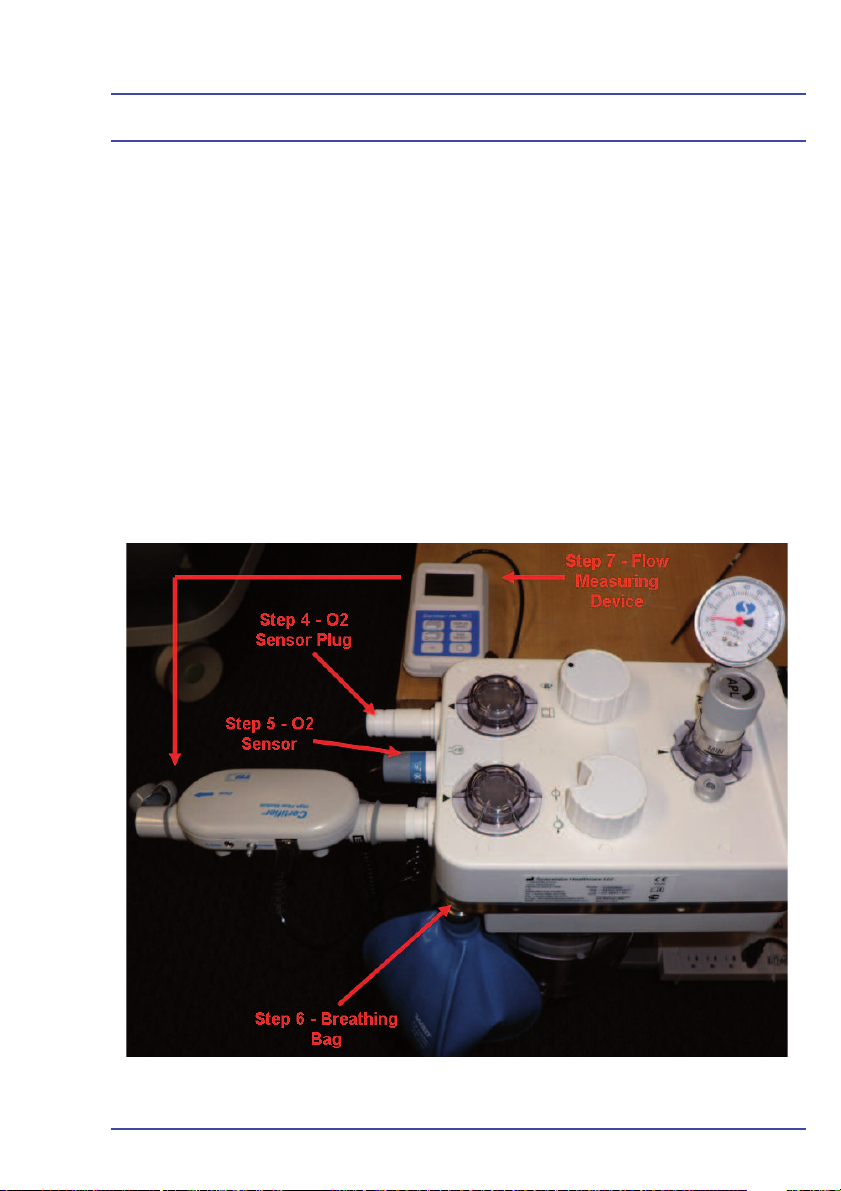
System Checks
4.14 Absorber Tests
If the machine is fi tted with an ACGO, ensure that the switch is set to
Absorber.
4.14.1 Expiratory Valve Leak Test
1. Remove all patient circuits from the Absorber.
2. Close the APL valve fully clockwise.
3. Set the Absorber bag/vent switch to bag.
4. Occlude the inspiratory outlet using the O
5. Occlude the O2 sensor port using the O2 sensor.
6. Attach a breathing bag to the bag port or bag arm.
7. Attach a fl ow measuring device on the expiratory port.
sensor plug.
2
Figure 31 - Expiratory Valve Test Setup
79
Page 80

System Checks
8. Pressurize the bag to 30 cmH
O (using absorber gauge) by turning up the
2
O2 fl ow. Once 30 cmH2O is reached, reduce the O2 back to its minimum
position.
9. Check the fl ow measuring device for any fl ow. Less than 60 ml/min is
acceptable.
10. If you fi nd a leak, replace the valve seat or valve disc. See Chapter 5 in
this service manual for replacement procedures.
4.14.2 Inspiratory Valve Leak Test
1. Remove the O
sensor plug and attach an additional breathing bag to the
2
inspiratory port (Figure 32).
Figure 32 - Setup for Inspiratory Valve Test
2. Pressurize the bag to 30 cmH
O (using the absorber gauge) by turning up
2
the O2 fl ow.
3. Remove the bag on the bag port and attach a fl ow measuring device as
indicated in Figure 33.
80
Page 81

System Checks
Figure 33 - Steps 3 & 4 of the Inspiratory Valve Test
4. Turn the power switch to the “OFF” position.
5. Gently squeeze the bag on the inspiratory port.
6. Check the fl ow measuring device for any fl ow. Less than 60 ml/min is
acceptable.
7. If you fi nd a leak, replace the valve seat or valve disc. See Chapter 5 in
this service manual for replacement procedures.
4.14.3 APL Valve Check
1. Ensure that an O
supply is
2
connected to the machine.
2. Ensure that all fl ow control valves
are closed.
3. Connect a pressure measuring
device to a pressure sampling tee.
Figure 34 - Connect a Pressure
Measuring Device
81
Page 82
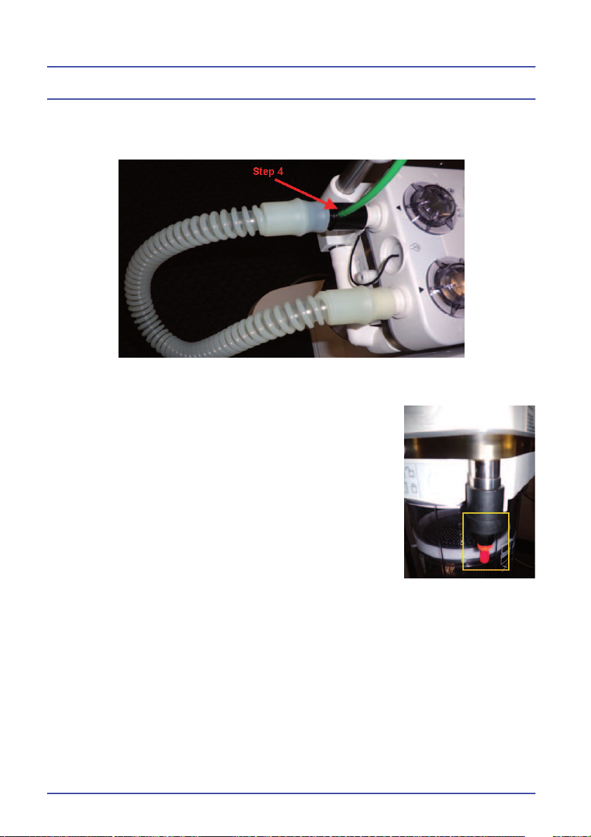
System Checks
4. Connect the pressure sampling tee to the inspiratory port and a 22 mm
reusable tube to the expiratory port and pressure sampling tee.
Figure 35 - Connect the Pressure Sampling Tee
5. Occlude the bag port.
6. Set the APL valve to “65”.
7. Turn the switch to the “ON” position and set a fl ow
of 6 L/min on the O
fl ow control valve.
2
8. Verify that the pressure measuring device reads
between 59-71 cmH20
9. Set the APL valve to “30”.
10. Verify that the pressure measuring device reads
between 24-36 cmH
11. Set the APL valve to “Min”.
12. Verify the pressure measuring device reads less
O
2
Figure 36 - Step 5:
Occlude the Bag Port
than 5 cmH2O.
82
Page 83

System Checks
4.15 Ventilator Test
If the machine is fi tted with an ACGO, ensure that the switch is set to
Absorber.
1. Ensure that the power switch is in the “OFF” position.
2. Ensure that all fl ow control valves are closed.
3. Ensure that a gas supply is connected to the pipeline inlets.
4. Turn the power switch to the “ON” position.
5. Perform the compliance test and systems check. Continue using
the same circuit used on the compliance and systems check for the
remainder of this check-out procedure.
6. Set the ventilator to “Stand by.”
7. Perform a CALBK calibration by pressing Setup > Confi guration > Service
Mode. Enter the password, CALBK. (Note: Do not perform “Front Panel
Zero”, as this will reset the VTI and VTE gain values back to defaults.)
8. Perform the “Flow Valve Calibration” by selecting this option on the
touchscreen.
9. Remove the drive gas hose from the rear of the machine and plug the
ventilator drive port.
!IMPORTANT! DO NOT PLUG THE EXHAUST PORT!
Figure 37 - Exhaust
Port Location
83
Page 84

System Checks
10. Perform the “Inspiratory Valve Cal” by selecting this option on the
touchscreen. Once complete, reconnect the drive gas hose onto the drive
gas fi tting.
11. Disconnect the patient hose from the
auxiliary plate.
12. Perform the “Block and Pressure Zeros”
calibration by selecting this option on the
touchscreen. Once complete, reconnect
the patient hose. Press “Home” on the
ventilator display.
13. Press Setup > Confi guration > Service
Mode. Enter the password, TECHY.
Figure 38 - Step 11: Disconnect
Patient Hose
14. Select “Touch Calibration”
and perform a touchscreen
calibration.
15. Select “Fresh Gas” to perform a
fresh gas calibration. Use the O
2
fl ow control valve to set 1-10 L/
min. If N2O is available, set O2
and N2O to 10 L/min in order
to set 20 L/min. If N2O is not
available, use O2 and Air. (Note:
To set 0 L/min, disconnect the
O2 supply from the machine and
press the O2 fl ush to release the
remaining O2. Once 0 L/min is
set, reconnect the O2 supply to
continue the calibration.
16. Connect a fl ow measuring device
to the inspiratory limb of the
breathing circuit as close to the
“Y” as possible. Connect a test
lung with a fi lter to the patient
fl ow sensor.
84
Figure 39 - Connect a Flow Measuring
Device
Page 85
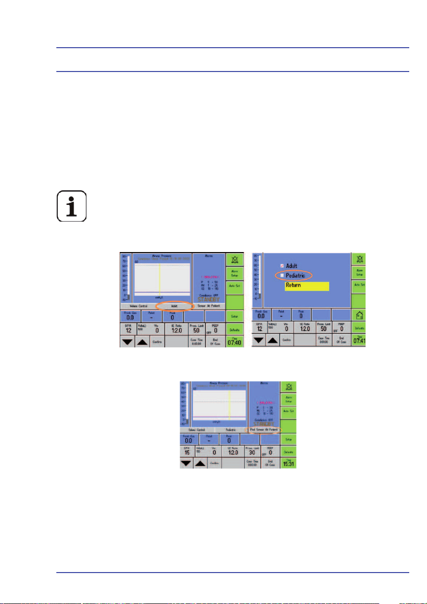
System Checks
17. Set the bag/vent switch on the absorber to Vent.
18. Run the ventilator in volume control mode with the following settings:
• Volume = 250 ml
• BPM = 8
• I:E = 1:2
• PEEP = OFF
19. Wait for the ventilator to stabilize.
For ventilators with front panel software 10.XX installed, use a
pediatric fl ow sensor when performing this step. Place the ventila-
tor in Standby. On the ventilator display, change the sensor setting from adult sensor to pediatric sensor (Figure 40A) and the
sensor placement setting to Pedi Sensor at Patient (Figure 40B).
Figure 40A - Change the Flow Sensor Settings
Figure 40B - Pedi Sensor Placement setting
20. Check that the inspired volume (VTI) on the fl ow measuring device is
250 ± 25 ml. Once complete, switch the ventilator back to adult mode and
use the adult fl ow sensor for the remaining checks.
21. Increase the tidal volume to 500 ml. Wait for the ventilator to stabilize.
85
Page 86

System Checks
22. Check that the inspired volume (VTI) on the fl ow measuring device is
500 ±50 ml.
23. Increase the tidal volume to 750 ml. Wait for the ventilator to stabilize.
24. Check that the inspired volume (VTI) on the fl ow measuring device is
750 ±75 ml.
If steps 20, 22 or 24 should fail, perform a PRAAA calibration according to the instructions given in PSN: 076-9027-00.
25. Place the ventilator in Standby. Connect a pressure measuring device to
the inspiratory port of the absorber (Figure 41).
Figure 41 - Connect a Pressure Measuring Device
26. Set the bag/vent switch to Vent.
27. Ensure that the bellows is full.
28. Set the PEEP on the ventilator to 10 cmH2O.
29. Verify that the pressure measuring device reads 10 ±1.5 cmH2O.
• Change the ventilator from volume control to pressure control mode at
the following settings: Pressure = 10 cmH2O
• BPM = 8
• I:E = 1:2
• PEEP = OFF
30. After 12 breaths, verify that the pressure measuring device reads
10 ± 2 cmH
O.
2
86
Page 87

System Checks
31. Increase the pressure to 30 cmH2O.
32. After 12 breaths, verify that the pressure measuring device reads 30 ±3
cmH2O.
33. Continuously squeeze test lung at the expiratory phase to simulate a high
pressure alarm. Ensure that the high pressure alarm is displayed on the
ventilator.
34. Remove all test equipment from the breathing circuit. Run the ventilator in
volume control mode with the following settings:
• Volume = 500 ml
• BPM = 8
• I:E = 1:2
• PEEP = OFF
35. Disconnect the O
supply and air supply (if fi tted). Verify that the following
2
alarms are displayed on the ventilator.
• Apnea
• Sustained Pressure
• Low Gas Pressure
• Pressure Low
Supply Fail
• O
2
36. Reconnect the O
and Air (if fi tted) supplies and let the ventilator stabilize.
2
37. Lower the pressure limit to 20 cmH2O. Secure the test lung so that it
cannot infl ate until the pressure limit alarm is displayed on the ventialtor
screen. After it is displayed, increase the pressure limit to 50 cmH2O.
38. Verify that the minute volume (MV) is displayed on the ventilator. Increase
the minute volume (MV) lower limit to 8, then verify that the Minute
Volume Low alarm is displayed on the ventilator.
39. Decrease the minute volume (MV) lower limit to 2 and the higher limit to
3. Verify that the Minute Volume High alarm is displayed.
40. Disconnect the O
sensor from the absorber and expose it to room
2
temperature. Wait for the O2 to read 21%. Increase the oxygen lower
alarm limit to 25, then ensure that the Oxygen Low alarm is displayed on
the ventilator.
Ensure that the O2 sensor used is calibrated.
87
Page 88

System Checks
41. Decrease the oxygen lower limit to 18% and the higher limit to 19%. Verify
that the Oxygen High alarm is displayed on the ventilator.
42. Disconnect the O
sensor, then verify that the O2 Sensor Error alarm is
2
displayed on the ventilator.
43. Disconnect the 700/900 ventilator AC power cord. Verify that the Mains
Fail alarm is displayed on the ventilator and that the green LED light turns
red.
44. Disconnect the AC power cord. Verify that the mains fail alarm is
displayed, the battery icon is displayed on the ventilator and that the
green LED light turns red.
45. Press Setup > Confi guration > System Information. Display the second
System Information screen and verify that the second battery voltage
(Switched) is greater than 11V. If not greater than 11V, ensure the unit
has had the battery continually charging for a minimum of 8hrs before
verifying. If the voltage is still low after 8 hours of continuous charge,
replace the battery.
System Information Screen #2, Battery (Unswitched/Switched)
Reading is greater Than 11 V
46. Slightly dismount the absorber. Verify that the Absorber Not Fitted alarm is
displayed on the ventilator.
47. Remount the absorber.
88
Page 89

System Checks
4.16 Vaporizer Output Concentration Check
1. Verify that the vaporizer being tested is fi lled to at least half its capacity.
2. Set the vaporizer dial to “0”.
3. Calibrate a gas analyzer (i.e. Riken) according to the manufacturer’s
instructions.
4. Ensure a waste gas scavenging systems is on, operational and is
connected to the absorber.
5. Connect a 22 mm reusable tube to the inspiratory and expiratory ports on
the absorber. Connect a breathing bag to the bag port.
Figure 42 - Step 5: Connect
a Reusable Tube
89
Page 90

System Checks
6. Connect a pressure sample tee to the CGO taper and the CGO boot to
the other end of the pressure sample tee. (Note: For ACGO units, connect
a 22 mm reusable hose from the other end of the pressure sampling tee
to the AGSS auxiliary port and set the switch to ACGO.)
Figure 43 - Connect a Pressure Sample Tee
7. Ensure that the pressure sampling tee is connected to a gas analyzer and
ensure that the gas analyzer is also connected to an active scavenger.
Figure 44 - Gas Analyzer Connection
8. Ensure that the bag-to-vent switch on the absorber is set to Bag. Open
the APL valve by turning it fully counter-clockwise.
9. Turn the power switch to the “ON” position.
10. Set a fl ow of 10 L/min on the O
fl ow control valve to fl ush the system of
2
any residual gas. Reduce the fl ow to 4 L/min after one minute.
11. Set the vaporizer dial to 1.0% and wait a few minutes for the vaporizer
concentration to stabilize.
90
Page 91

System Checks
12. Verify that the reading on the gas analyzer is between 0.8 – 1.2%.
13. Set the vaporizer dial to 2.5% and wait a few minutes for the vaporizer
concentration to stabilize.
14. Verify that the reading on the gas analyzer is between 2.0 – 3.0%.
15. Set the vaporizer dial to 5.0% and wait a few minutes for the vaporizer
concentration to stabilize.
16. Verify that the reading on the gas analyzer is between 4.0 – 6.0%.
17. If a Sevofl ourane vaporizer is being tested, set the vaporizer dial to 8.0%
and wait a few minutes for the vaporizer concentration to stabilize.
18. Verify that the reading on the gas analyzer is between 6.4 – 9.6%.
19. If a Desfl urane vaporizer is being tested, set the vaporizer dial to 10.0%
and wait a few minutes for the vaporizer concentration to stabilize.
20. Verify that the reading on the gas analyzer is between 8.0 – 12.0%.
21. Set the vaporizer dial to 18.0% and wait a few minutes for the vaporizer
concentration to stabilize.
22. Verify that the reading on the gas analyzer is between 14.4 – 21.6%.
23. Set the vaporizer dial to “0”.
24. Set the O
fl ow control valve to minimum fl ow and turn the switch to the
2
“OFF” position.
4.17 Electrical Safety Test
1. Connect the BleaseSirius anesthesia machine to an approved safety
analyzer. Verify that the leakage current is less than 300 µΑmps for
120/100 Vac and less than 500 µΑmps for 220/240 Vac
2. Connect the ground pin of the safety analyzer to an external grounding
plug. Verify that the resistence to ground is less than 0.2 Ω.
91
Page 92

System Checks
4.18 Complete the BleaseSirius Checkout Sheet
1. Complete the BleaseSirius Checkout Sheet.
2. Sign and date the form and ask the customer representative to also sign
and date the form.
3. Make 2 copies of the completed form. Leave one copy with the customer,
keep one copy for your records and submit the original form with your
service report.
92
Page 93

BleaseSirius
Anesthetic Machine
Chapter 5
Detailed Repair
Procedures
93
Page 94

Detailed Repair Procedures
94
Page 95

Detailed Repair Procedures
5.1 Removal/Replacement Instructions
When any repair or exchange is performed on internal components, a complete
check must be made on all functions. A complete overall performance check
must also be performed when any replacements or repairs have been completed.
5.1.1 Removal of Outer Cases (on units up to Jan 2009)
Figure 45 - Removal of Top Surface
1. Remove the 4 screws shown in Figure 45 and lift the top cover off.
95
Page 96

Detailed Repair Procedures
Figure 46 - Removal of Screw as Shown
96
Figure 47 - Removal of Top Screws as Shown
Page 97

Detailed Repair Procedures
2. Ensure work surface is
clear,then slide the front
cover forwards in the direction
shown.
Figure 48 - Removal of Front Cover
5.1.2 Removal of Outer Cases (on units after Jan 2009)
1. Loosen the four screws that hold the
top shelf in place. You do not need to
completely remove them.
2. Remove the two screws securing
the front cover to the BleaseSirius.
Figure 49 - Front Cover Fixing Screws (on units after Jan 2009)
97
Page 98

Detailed Repair Procedures
3. Remove the four screws
that hold the plate behind
the back bar and slide the
plate out from behind the
back bar.
4. Slide the front cover off the
BleaseSirius.
98
Page 99

Detailed Repair Procedures
Figure 50 - Front of Machine With Front Cover Removed (Close-up)
99
Page 100

Detailed Repair Procedures
Figure 51 - Rear of Machine
(Not necessary for Routine Service)
5. Remove the back cover - Remove all pipelines and cylinders before
removing the screws shown in Figure 51.
100
 Loading...