

Page 1

Multigas Analyzer
91518
Service Manual
070-1328-00 Rev. E
Page 2

©2008 Spacelabs Medical, Inc.
Rx Only
!
All rights reserved. Contents of this publication may not be reproduced in any form without the written permission of
Spacelabs Medical. Products of Spacelabs Medical are covered by U.S. and foreign patents and/or pending patents.
Printed in U.S.A. Specifications and price change privileges are reserved.
Spacelabs Medical considers itself responsible for the effects on safety, reliability and performance of the equipment
only if:
• assembly operations, re-adjustments, modifications or repairs are carried out by persons authorized by
Spacelabs Medical, and
• the electrical installation of the relevant room complies with the requirements of the standard in force, and
• the equipment is used in accordance with the operations manual.
Spacelabs Medical will make available, on request, such circuit diagrams, component part lists, descriptions,
calibration instructions or other information which will assist appropriately qualified technical personnel to repair those
parts of the equipment which are classified by Spacelabs Medical as field repairable.
Spacelabs Medical is committed to providing comprehensive customer support beginning with your initial inquiry
through purchase, training, and service for the life of your Spacelabs Medical equipment.
CORPORATE OFFICES
U.S.A.
Spacelabs Medical, Inc.
5150 220th Ave SE
Issaquah, WA 98029
Telephone: 425-657-7200
Telephone: 800-522-7025
Fax: 425-657-7212
Authorized EC Representative UNITED KINGDOM
Spacelabs Healthcare, Ltd.
Beech House, Chiltern Court
Asheridge Road, Chesham
Buckinghamshire HP5 2PX
Telephone: 44 (0) 1494 784422
Fax: 44 (0) 1494 794414
BirthNet, Clinical Browser, Data Shuttle, Flexport, Intesys, Mermaid, MOM, Multiview, PCIS, PCMS, PrintMaster,
Quicknet, Sensorwatch, TRU-CAP, TRU-CUFF, TruLink, Ultralite, Ultraview, Ultraview Care Network, Ultraview Clinical
Messenger, Ultraview Digital Telemetry, Ultraview SL, Uni-Pouch, UCW, Varitrend and WinDNA are trademarks of
Spacelabs Medical, Inc.
Other brands and product names are trademarks of their respective owners.
Caution:
US Federal law restricts the devices documented herein to sale by, or on the order of, a
physician.
Before use, carefully read the instructions, including all warnings and cautions.
Page 3

Table of Contents
Contents Page
Introduction
Overview. . . . . . . . . . . . . . . . . . . . . . . . . . . . . . . . . . . . . . . . . . . . . . . . . . . . . . . . . . . . . . . . . . . . . . . . . . . . . . . . . 1-1
Compatibility . . . . . . . . . . . . . . . . . . . . . . . . . . . . . . . . . . . . . . . . . . . . . . . . . . . . . . . . . . . . . . . . . . . . . . . . . . . . . . 1-2
Dimensions. . . . . . . . . . . . . . . . . . . . . . . . . . . . . . . . . . . . . . . . . . . . . . . . . . . . . . . . . . . . . . . . . . . . . . . . . . . . . . . 1-2
Environmental Requirements . . . . . . . . . . . . . . . . . . . . . . . . . . . . . . . . . . . . . . . . . . . . . . . . . . . . . . . . . . . . . . . . . 1-3
Controls and Connectors . . . . . . . . . . . . . . . . . . . . . . . . . . . . . . . . . . . . . . . . . . . . . . . . . . . . . . . . . . . . . . . . . . . . 1-4
Setup
Unpacking. . . . . . . . . . . . . . . . . . . . . . . . . . . . . . . . . . . . . . . . . . . . . . . . . . . . . . . . . . . . . . . . . . . . . . . . . . . . . . . . 2-1
Safety Checks . . . . . . . . . . . . . . . . . . . . . . . . . . . . . . . . . . . . . . . . . . . . . . . . . . . . . . . . . . . . . . . . . . . . . . . . . . . . 2-1
Multigas Setup . . . . . . . . . . . . . . . . . . . . . . . . . . . . . . . . . . . . . . . . . . . . . . . . . . . . . . . . . . . . . . . . . . . . . . . . . . . . 2-2
Power Up Verification . . . . . . . . . . . . . . . . . . . . . . . . . . . . . . . . . . . . . . . . . . . . . . . . . . . . . . . . . . . . . . . . . . . . . . 2-14
Theory
Overview. . . . . . . . . . . . . . . . . . . . . . . . . . . . . . . . . . . . . . . . . . . . . . . . . . . . . . . . . . . . . . . . . . . . . . . . . . . . . . . . . 3-1
Interface PCBA. . . . . . . . . . . . . . . . . . . . . . . . . . . . . . . . . . . . . . . . . . . . . . . . . . . . . . . . . . . . . . . . . . . . . . . . . . . . 3-3
Gas Analyzer Unit. . . . . . . . . . . . . . . . . . . . . . . . . . . . . . . . . . . . . . . . . . . . . . . . . . . . . . . . . . . . . . . . . . . . . . . . . . 3-4
Maintenance
Overview. . . . . . . . . . . . . . . . . . . . . . . . . . . . . . . . . . . . . . . . . . . . . . . . . . . . . . . . . . . . . . . . . . . . . . . . . . . . . . . . . 4-1
Preventive Maintenance . . . . . . . . . . . . . . . . . . . . . . . . . . . . . . . . . . . . . . . . . . . . . . . . . . . . . . . . . . . . . . . . . . . . . 4-2
Corrective Maintenance . . . . . . . . . . . . . . . . . . . . . . . . . . . . . . . . . . . . . . . . . . . . . . . . . . . . . . . . . . . . . . . . . . . . 4-16
Disassembly and FRU Replacement . . . . . . . . . . . . . . . . . . . . . . . . . . . . . . . . . . . . . . . . . . . . . . . . . . . . . . . . . . 4-24
Troubleshooting
Tools and Equipment . . . . . . . . . . . . . . . . . . . . . . . . . . . . . . . . . . . . . . . . . . . . . . . . . . . . . . . . . . . . . . . . . . . . . . . 5-1
Problem Solving . . . . . . . . . . . . . . . . . . . . . . . . . . . . . . . . . . . . . . . . . . . . . . . . . . . . . . . . . . . . . . . . . . . . . . . . . . . 5-1
Parts
Field Replaceable Parts . . . . . . . . . . . . . . . . . . . . . . . . . . . . . . . . . . . . . . . . . . . . . . . . . . . . . . . . . . . . . . . . . . . . . 6-1
Drawings. . . . . . . . . . . . . . . . . . . . . . . . . . . . . . . . . . . . . . . . . . . . . . . . . . . . . . . . . . . . . . . . . . . . . . . . . . . . . . . . . 6-5
Appendix A — Electromagnetic Compatibility
Electromagnetic Emissions. . . . . . . . . . . . . . . . . . . . . . . . . . . . . . . . . . . . . . . . . . . . . . . . . . . . . . . . . . . . . . . . . . . A-1
Frequency Separation Distances . . . . . . . . . . . . . . . . . . . . . . . . . . . . . . . . . . . . . . . . . . . . . . . . . . . . . . . . . . . . . . A-3
Appendix B — Symbols
90518 Multigas Analyzer Service Manual i
Page 4

Page 5
Introduction
Contents
Overview. . . . . . . . . . . . . . . . . . . . . . . . . . . . . . . . . . . . . . . . . . . . . . . . . . . . . . . . . . . . . . . . . . . . . . . . . . . . . . .1
Dimensions . . . . . . . . . . . . . . . . . . . . . . . . . . . . . . . . . . . . . . . . . . . . . . . . . . . . . . . . . . . . . . . . . . . . . . . . . . . . .2
Environmental Requirements . . . . . . . . . . . . . . . . . . . . . . . . . . . . . . . . . . . . . . . . . . . . . . . . . . . . . . . . . . . . . . .3
Controls and Connectors . . . . . . . . . . . . . . . . . . . . . . . . . . . . . . . . . . . . . . . . . . . . . . . . . . . . . . . . . . . . . . . . . .4
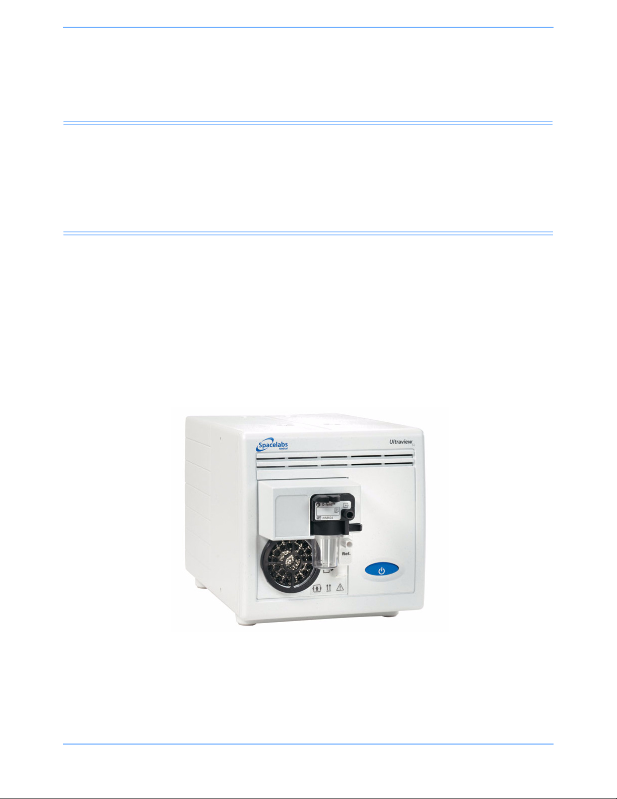
Overview
The 91518 is a multigas analyzer used primarily in an operating room environment to measure the CO2
produced by a patient and the O
are monitored are halothane, isoflurane, enflurane, sevoflurane, and desflurane.
The 91518 Multigas Analyzer interfaces to a Spacelabs Healthcare monitor through an SDLC connection. The
Spacelabs Healthcare monitor provides the numeric display for gas concentrations, a respiratory rate, and a
capnograph waveform for CO
, N2O, and anesthetic agents being administered. The anesthetic agents that
2
.
2
Multigas Analyzer
Figure 1-1: 91518 Multigas Analyzer
Spacelabs Healthcare products are designed and manufactured under good manufacturing practices and in
compliance with all applicable regulatory requirements. To ensure proper operation in accordance with these
guidelines, this product must be maintained by trained technicians using Spacelabs Healthcare authorized
replacement parts.
91518 Multigas Analyzer Service Manual 1-1
Page 6

Introduction
Compatibility
The 91518 Multigas Analyzer is designed for use with Ultraview SL, Ultraview, and UCW® monitors.
Ultraview SL
• Ultraview SL2400 (91369), SL2600 (91370), SL2700 (91387-27), SL2800 (91387-28)
Ultraview
• UCW (90385)*, Ultraview 1700 (90387)*, Ultraview 1500 (90363), Ultraview 1600 (90364), Ultraview 1050
(90369), Ultraview
* Some UCW (S/N below 385-3xxxxx) and Ultraview monitors (S/N below 387-1xxxxx) do not support all
waveforms and display options, such as colors.
™
®
1030 (90367)
Dimensions
Height 17.15 cm (6.75 inches) (enclosure: 14.605 cm [5.75 inches]); feet: 1.27 cm
(0.5 inches)
Width 15.24 cm (6 inches)
Depth 28.45 cm (11.2 inches) (enclosure: 21.59 cm [8.5 inches]); gas module protrudes
from front 4.572 cm (1.8 inches); handle in back of enclosure protrudes 2.286 cm
(0.9 inches)
Weight 3.714 kg (8.19 lbs)
91518 Multigas Analyzer Service Manual 1-2
Page 7
Introduction
Environmental Requirements
Table 1 lists the environmental requirements, including temperature, for operating and storing the 91518
Multigas Analyzer.
Table 1: Environmental Requirements
Operating Storage
Temperature
Humidity
Altitude N/A 12,192 m (40,000 feet)
Atmospheric Pressure
18° to 28° C (64.4° to 82.4° F),
±5° C of calibration
20 to 80% (non-condensing)
relative humidity (RH), ±20%
RH of calibration
500 to 800 mmHg, ±50mmHg
of calibration
-25° to 70° C (-13° to 158° F)
10 to 95% (non-condensing)
N/A
91518 Multigas Analyzer Service Manual 1-3
Page 8
Introduction
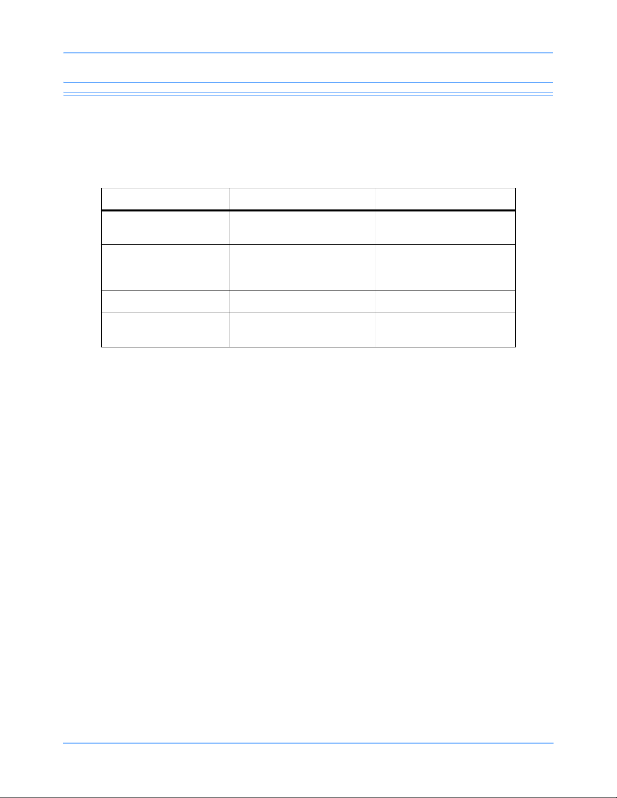
Controls and Connectors
The blue power ON/OFF switch is located on the front of the analyzer.
All other multigas analyzer functions are controlled using the touch keys on Spacelabs Healthcare monitors.
Front View
Figure 1-2: Front view of the 91518 Multigas Analyzer
Gas sampling line inlet connector
Replaceable D-fend water trap
Reference gas port (no connection)
Power ON/OFF switch
Gas outlet port
Fan and filter
91518 Multigas Analyzer Service Manual 1-4
Page 9
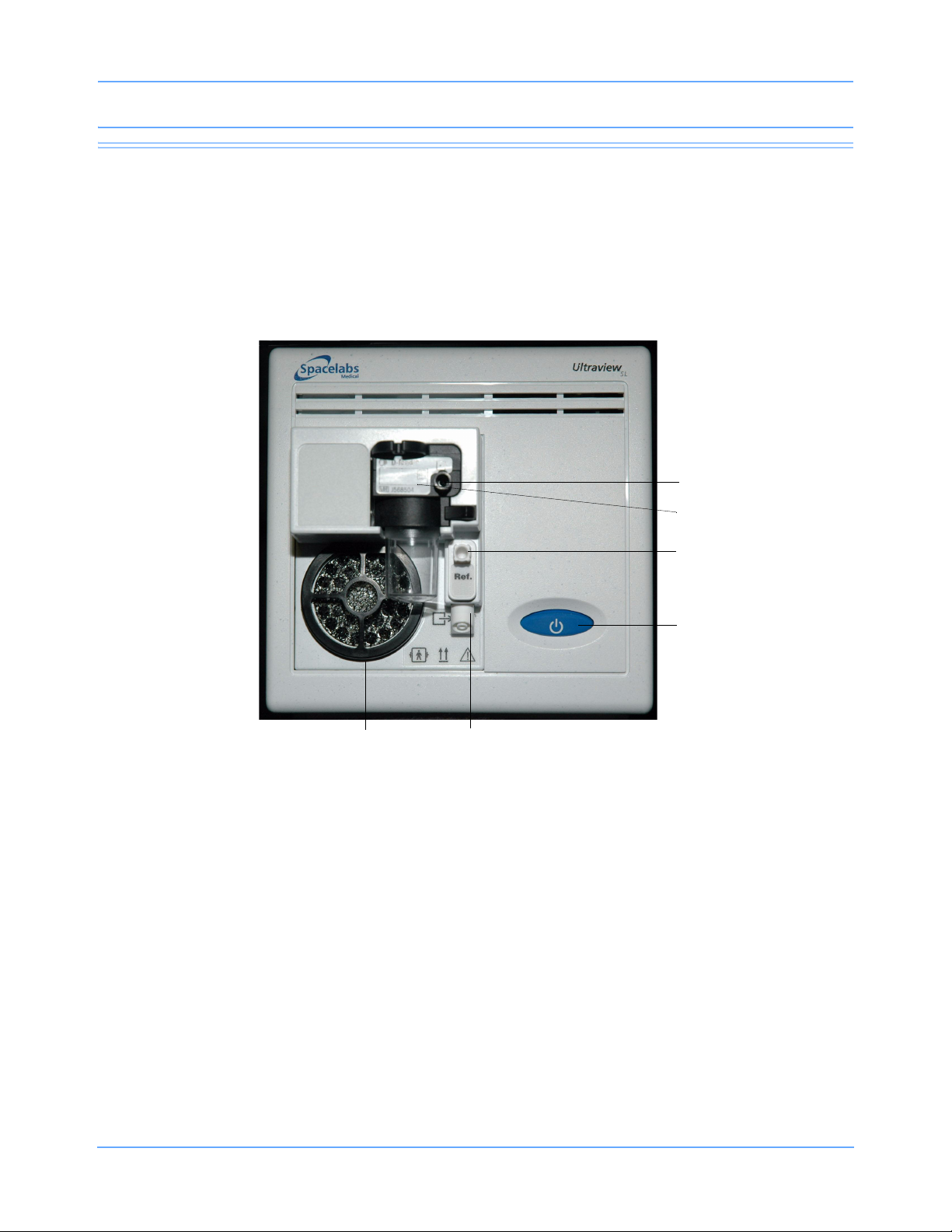
Rear View
Introduction
Figure 1-3: Rear of 91518 Multigas Analyzer
9 pin SDLC connector (J2)
RS-232 connector (J1)
SDLC terminator
Equipotential ground terminal
26-pin SDLC connector (J3)
Power connection
91518 Multigas Analyzer Service Manual 1-5
Page 10

Page 11

Setup
Contents
Unpacking. . . . . . . . . . . . . . . . . . . . . . . . . . . . . . . . . . . . . . . . . . . . . . . . . . . . . . . . . . . . . . . . . . . . . . . . . . . . . .1
Safety Checks. . . . . . . . . . . . . . . . . . . . . . . . . . . . . . . . . . . . . . . . . . . . . . . . . . . . . . . . . . . . . . . . . . . . . . . . . . .1
Multigas Setup . . . . . . . . . . . . . . . . . . . . . . . . . . . . . . . . . . . . . . . . . . . . . . . . . . . . . . . . . . . . . . . . . . . . . . . . . .2
Power Up Verification . . . . . . . . . . . . . . . . . . . . . . . . . . . . . . . . . . . . . . . . . . . . . . . . . . . . . . . . . . . . . . . . . . . .14
Unpacking
Before unpacking the 91518 Multigas Analyzer, inspect its shipping container for visible damage. Unpack and
remove the multigas analyzer from its container. Check the multigas analyzer's exterior for signs of physical
damage. Be sure to check the SDLC connectors (refer to Figure 1-3 on page 1-5) on the back of the multigas
analyzer for bent pins. If any damage is apparent, notify the carrier and Spacelabs Healthcare immediately.
Please follow your hospital’s procedure regarding the disposal or recycling of packaging waste.
Equipment Inventory
The following items are included with the 91518 Multigas Analyzer:
• Gas sampling input line
Safety Checks
Physical Inspection
Visually inspect the unit to verify that it is physically sound (no loose hardware, no damaged fittings, clean fan
filter, etc.).
Table 1: Summary of Standards for Medical Monitoring Equipment
International Mains to
Chassis Leakage
100 μA - normal condition, ground
attached (AC connector to chassis)
500 μA - single fault condition, open
ground or reverse polarity
300 μA - normal condition, ground
attached (AC connector to chassis)
300 μA - single fault condition, open
ground or reverse polarity
U.S. (120 V) Mains to
Chassis Leakage
Mains Resistance
500 milliohms*
200 milliohms*
* Measured from the AC Power cord third wire ground to the most distant ground attachment
91518 Multigas Analyzer Service Manual 2-1
Page 12
Setup
Non-terminated Terminated
Multigas Setup
Sampling Lines
The sampling lines used with a 91518 Multigas Analyzer must be constructed of a material that will not absorb
anesthetic agents and cause erroneous readings. The correct sample lines are available from Spacelabs
Healthcare. Refer to Parts on page 6-1.
Power Supply
The 91518 can be powered from the J3 SDLC connector from the patient monitor or module housing, or it can
be powered from an external power supply, P/N 119-0479-xx.
SDLC Bus Termination
The SDLC bus must be properly terminated for correct operation. Termination of the SDLC bus is
accomplished by means of terminator switches on the rear of the monitor and the multigas analyzer, or by a
terminator plug P/N 012-0507-02, when connected to a portable monitor.
Figure 2-1: Terminator switch settings
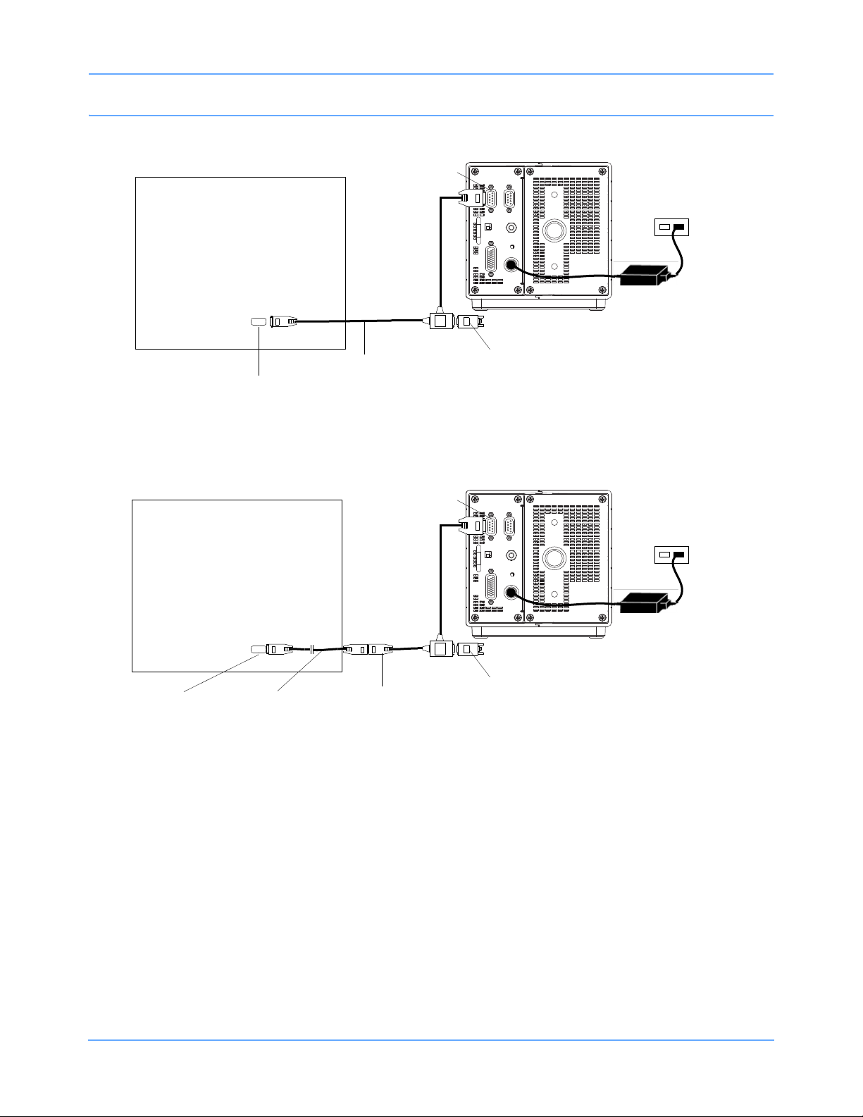
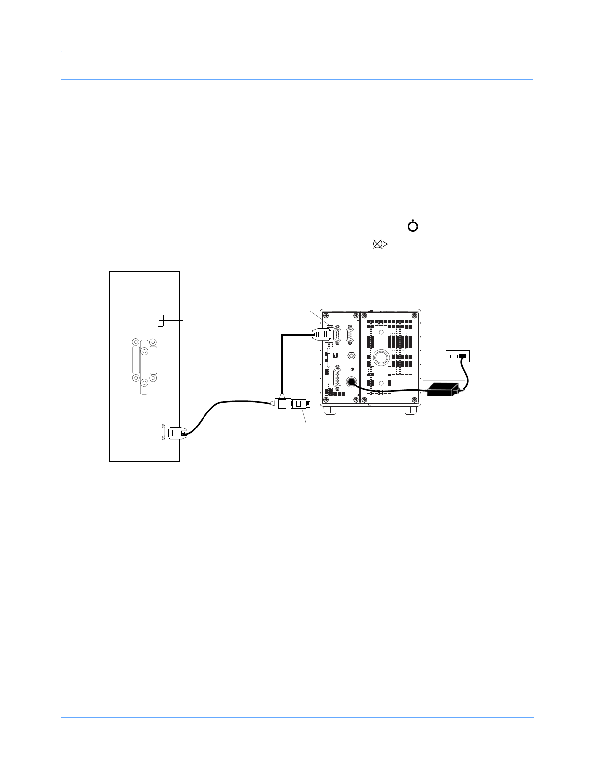
90367/69, 91369, 91370 Monitor Installations
To install the 91518 with 90367/69, 91369, 91370 monitors:
1 Verify that AC power is connected as required by local standards. An external power supply
(P/N
119-0480-00 or 119-0251-00) is required for use with the 91518 Multigas Analyzer.
2 Ensure that the monitor and multigas analyzer are powered OFF.
3 Assemble the required cables and terminators for your system configuration (refer to Figure 2-2 for part
numbers).
4 Connect the P1 connector of the tee cable (P/N 012-0175-01) to the SDLC jack (J2) on the 91518 rear panel
(refer to
Note:
An extension cable (6-foot SDLC extension cable [P/N 012-0619-00] or 3-foot SDLC extension cable
[P/N
(refer to
5 Connect the SDLC terminator to the P2 connector of the tee cable.
6 Connect the SDLC cable to the monitor.
7 Set the SDLC switch on the 91518 Multigas Analyzer to terminated ( ).
Figure 1-3 on page 1-5 for rear panel information).
012-0242-00]) can be connected to the tee cable to extend the distance of the 91518 from the monitor
Figure 2-3 on page 2-3).
91518 Multigas Analyzer Service Manual 2-2
Page 13
Setup
jack (J2)
P/N 012-0175-01
SDLC
terminator
P/N 012-0507-02
SDLC
SDLC
....
.....
tee cable
91518
90367/69/91369/91370
monitor
jack
AC power
source
Power supply
P/N 119-0480-00
jack (J2)
P/N 012-0175-01
SDLC
terminator
P/N 012-0507-02
SDLC
SDLC
....
.....
tee cable
91518
90367/69/91369/91370
monitor
jack
AC power
source
Power supply
P/N 119-0480-00
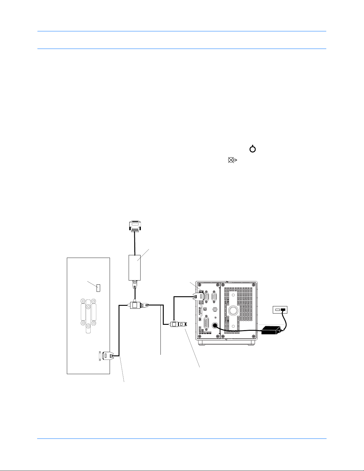
extension cable
P/N 012-0619-00
or 012-0242-00
Figure 2-2: 91518 connections to 90367/69, 91369, 91370 monitors
91518 Multigas Analyzer Service Manual 2-3
Figure 2-3: 91518 connections to 90367/69, 91369, 91370 monitors, using extension cable
Page 14
Setup
jack (J2)
P/N 012-0175-01
SDLC
terminator
P/N 012-0507-02
SDLC
SDLC
....
.....
tee cable
91518
90367/69/91369/91370
monitor
jack
AC power
source
Power supply
P/N 119-0480-00
P/N 012-0152-00
tee cable
To peripheral device
Flexport interface
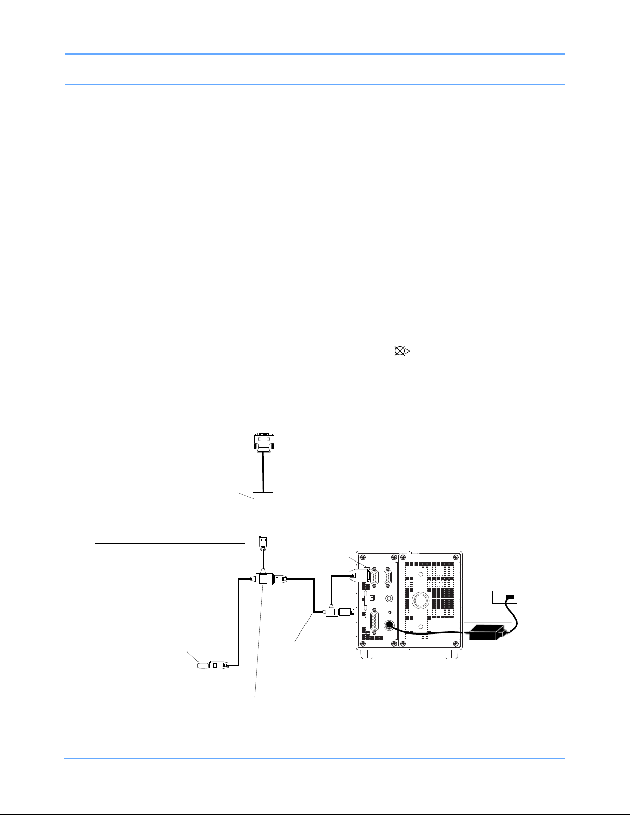
90367/69, 91369, 91370 Monitor Installations with Flexport
To install the 91518 with 90367/69, 91369, 91370 monitors:
1 Verify that AC power is connected as required by local standards. An external power supply
(P/N
119-0480-00 or 119-0251-00) is required for use with the 91518 Multigas Analyzer.
2 Ensure that the monitor and multigas analyzer are powered OFF.
3 Assemble the required cables and terminators or your system configuration (refer to Figure 2-4 for part
numbers).
4 Connect the P1 connector of the tee cable (P/N 012-0175-01) to the SDLC jack (J2) on the 91518 rear panel
(refer to
Note:
An extension cable (6-foot SDLC extension cable [P/N 012-0619-00] or 3-foot SDLC extension cable
[P/N
(refer to
5 Connect P3 of the Flexport tee cable (P/N 012-0152-00) to P2 of the tee cable (P/N 012-0175-01).
6 Connect P1 of the Flexport cable to the monitor.
7 Set the SDLC switch on the 91518 Multigas Analyzer to terminated ( ).
Figure 1-3 on page 1-5 for rear panel information).
012-0242-00]) can be connected to the tee cable to extend the distance of the 91518 from the monitor
Figure 2-5 on page 2-5).
Note:
If using more than one Flexport, Spacelabs Healthcare recommends the use of the Flexport Holder
(P/N
650-0201-00).
91518 Multigas Analyzer Service Manual 2-4
Figure 2-4: 91518 connections to 90367/69, 91369, 91370 monitors, with Flexport
Page 15
Setup
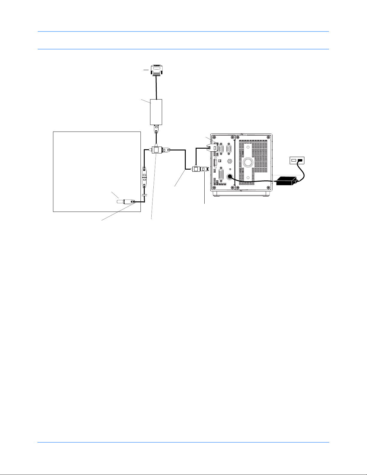
jack (J2)
P/N 012-0175-01
SDLC
terminator
P/N 012-0507-02
SDLC
SDLC
....
.....
tee cable
91518
90367/69/91369/91370
monitor
jack
AC power
source
Power supply
P/N 119-0480-00
P/N 012-0152-00
tee cable
To peripheral device
Flexport interface
extension cable
P/N 012-0619-00
or 012-0242-00
91518 Multigas Analyzer Service Manual 2-5
Figure 2-5: 91518 connections to 90367/69, 91369, 91370 monitors,
using Flexport and extension cable
Page 16
Setup
P/N 012-0601-xx
SDLC
jack (J3)
cable
91387
SDLC
jack (J9)
91518
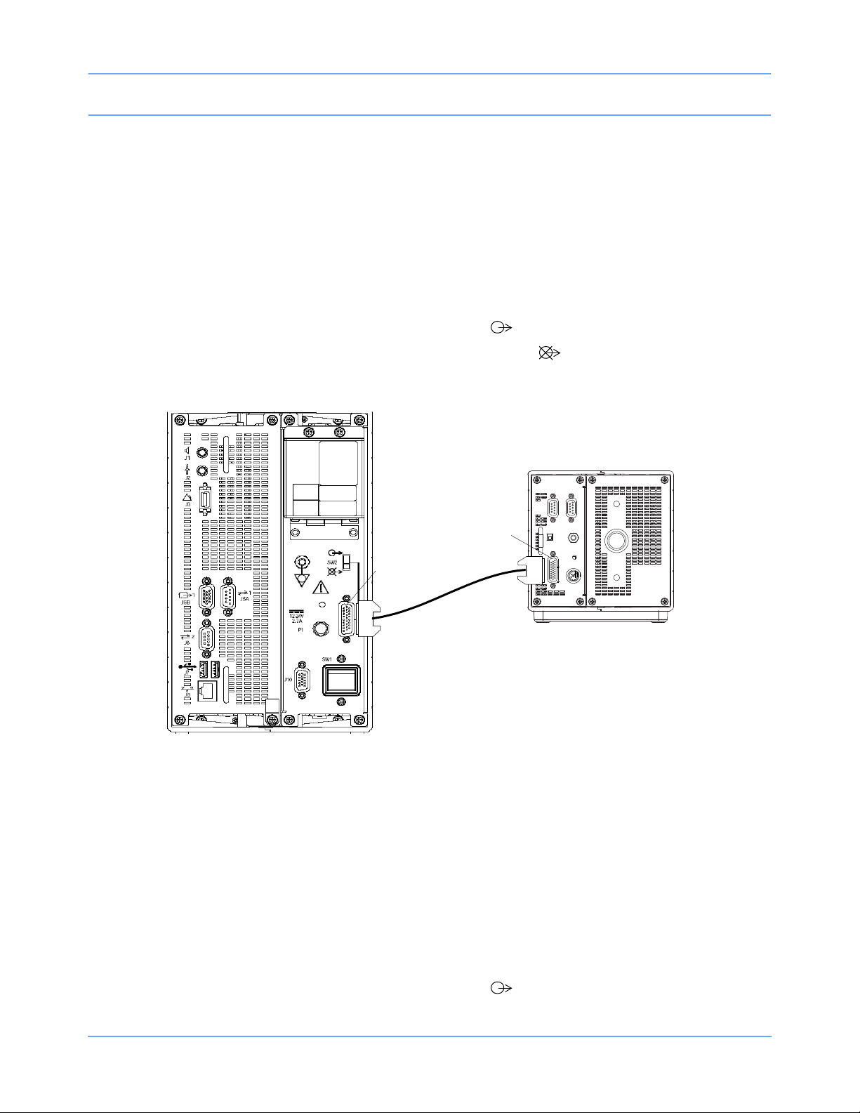
91387 Monitor Installation
To install the 91518 with the 91387 monitor:
1 Verify that the AC power is connected as required by local standards. The 91518 Multigas Analyzer will not
require the use of an external power supply.
2 Ensure that the monitor and multigas analyzer are powered OFF.
3 Assemble the required cables for your system configuration (refer to Figure 2-6 for part numbers).
4 Connect the SDLC cable (P/N 012-0601-xx) to the SDLC jack (J3) on the 91518 rear panel (refer to
Figure 1-3 on page 1-5 for rear panel information) and to the SDLC (J9) of the monitor.
5 Set the SDLC switch on the 91387 monitor to unterminated ( ).
6 Set the SDLC switch on the 91518 Multigas Analyzer to terminated ( ).
Figure 2-6: 91518 connections to 91387 monitor, using power from monitor
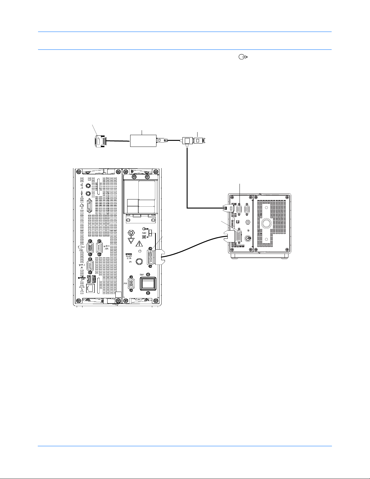
91387 Monitor Installation with Flexport
To install the 91518 with the 91387 monitor:
1 Verify that the AC power is connected as required by local standards. The 91518 Multigas Analyzer will not
require the use of an external power supply.
2 Ensure that the monitor and multigas analyzer are powered OFF.
3 Assemble the required cables for your system configuration (refer to Figure 2-7 for part numbers).
4 Connect the SDLC cable (P/N 012-0601-xx) to the SDLC jack (J3) on the 91518 rear panel (refer to
Figure 1-3 on page 1-5 for rear panel information) and to the SDLC (J9) of the monitor.
5 Set the SDLC switch on the 91387 monitor to unterminated ( ).
91518 Multigas Analyzer Service Manual 2-6
Page 17
Setup
P/N 012-0601-xx
SDLC
jack (J3)
cable
91387
SDLC
jack (J9)
91518
P/N 012-0152-00
cable
Flexport
To peripheral
device
interface
SDLC
jack (J2)
SDLC terminator
P/N 012-0507-02
6 Set the SDLC switch on the 91518 Multigas Analyzer to unterminated ( ).
7 Connect the Flexport cable (012-0152-00) to J2 of the multigas analyzer.
Note:
If using more than one Flexport, Spacelabs Healthcare recommends the use of the Flexport Holder
(P/N
650-0201-00).
Figure 2-7: 91518 connections to 91387 monitor, with Flexport
91518 Multigas Analyzer Service Manual 2-7
Page 18
Setup
J2
J3
P/N 012-0601-xx
SDLC
jack (J3)
cable
90364/90491/
90499/90387
91518
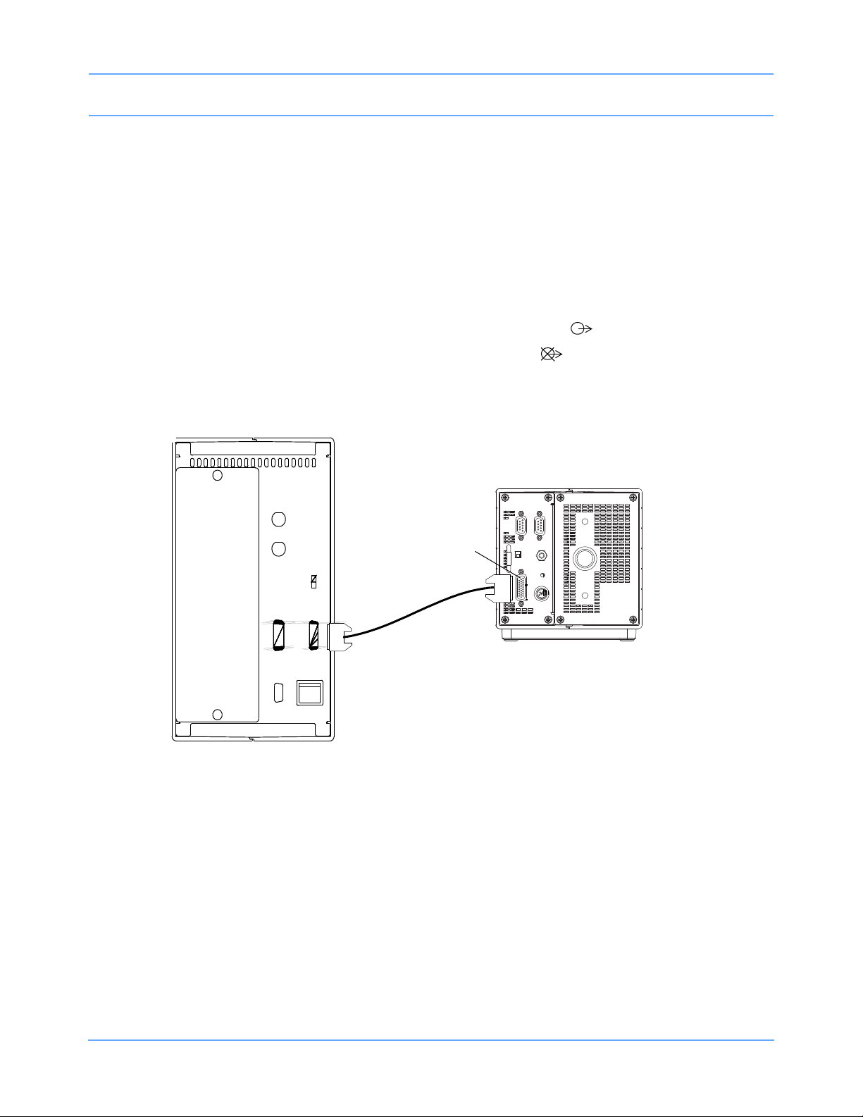
90364, 90491, 90499, and 90387 Module Housing or Monitor Installations
To install the 91518 with 90364, 90491, 90499, and 90387 module housings or monitors:
1 Verify that the AC power is connected as required by local standards. The 91518 Multigas Analyzer will not
require the use of an external power supply.
2 Ensure that the monitor or module housing and multigas analyzer are powered OFF.
3 Assemble the required cables for your system configuration (refer to Figure 2-8 for part numbers).
4 Connect the SDLC cable (P/N 012-0601-xx) to the SDLC jack (J3) on the 91518 rear panel (refer to
Figure 1-3 on page 1-5 for rear panel information) and to the SDLC (J2) of the monitor or module housing.
5 Set the SDLC switch on the 90364/90491/90499/90387 to unterminated ( ).
6 Set the SDLC switch on the 91518 Multigas Analyzer to terminated ( ).
Figure 2-8: 91518 connections to 90364, 90491, 90499, and 90387 monitors or housings
91518 Multigas Analyzer Service Manual 2-8
Page 19
Setup
J2
J3
P/N 012-0601-xx
SDLC
jack (J3)
cable
90364/90491/
90499/90387
91518
SDLC
jack (J2)
To peripheral
Flexport
SDLC terminator P/N 012-0507-02
interface
P/N 012-0152-00
cable
device
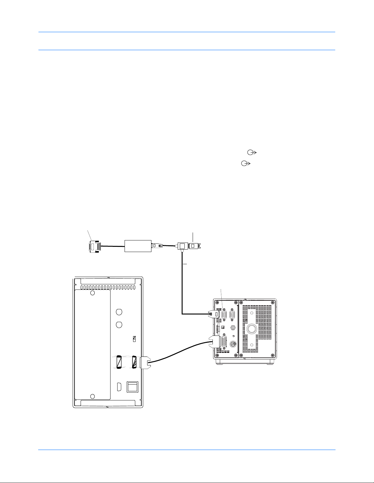
90364, 90491, 90499, and 90387 Module Housing or Monitor Installations with Flexport
To install the 91518 with 90364, 90491, 90499, and 90387 module housings or monitors:
1 Verify that the and AC power is connected as required by local standards. The 91518 Multigas Analyzer will
not require the use of an external power supply.
2 Ensure that the monitor or module housing and multigas analyzer are powered OFF.
3 Assemble the required cables for your system configuration (refer to Figure 2-9 for part numbers).
4 Connect the SDLC cable (P/N 012-0601-xx) to the SDLC jack (J3) on the 91518 rear panel (refer to
Figure 1-3 on page 1-5 for rear panel information) and to the SDLC (J2) of the monitor or module housing.
5 Set the SDLC switch on the 90364/90491/90499/90387 to unterminated ( ).
6 Set the SDLC switch on the 91518 Multigas Analyzer to unterminated ( ).
7 Connect the Flexport cable (012-0152-00) to J2 of the multigas analyzer.
Note:
If using more than one Flexport, Spacelabs Healthcare recommends the use of the Flexport Holder
(P/N
650-0201-00).
Figure 2-9: 91518 connections to 90364, 90491, 90499, and 90387 monitors or housings,
91518 Multigas Analyzer Service Manual 2-9
with Flexport
Page 20
Setup
J6
90485 Remote
P/N 012-0175-01
SDLC
terminator
P/N 012-0507-02
SDLC
jack (J2)
91518
SDLC termination
switch
Module Housing
tee cable
AC power
Power supply
P/N 119-0480-00
90485 Remote Module Housing Installation
1 Verify that AC power is connected as required by local standards. An external power supply
(P/N
119-0480-00 or 119-0251-00) is required for use with the 91518 Multigas Analyzer.
2 Ensure that the module housing and multigas analyzer are powered OFF.
3 Assemble the required cables for your system configuration (refer to Figure 2-10 for part numbers).
4 Connect the P1 connector of the tee cable (P/N 012-0175-01) to the SDLC jack (J2) on the 91518 rear panel
(refer to
5 Connect P2 of the tee cable (P/N 012-0175-01) to the remote module housing.
6 Set the SDLC switch on the 90485 remote module housing to unterminated ( ).
7 Set the SDLC switch on the 91518 Multigas Analyzer to terminated ( ).
Figure 1-3 on page 1-5 for rear panel information).
91518 Multigas Analyzer Service Manual 2-10
Figure 2-10: 91518 connections to a remote module housing
Page 21
Setup
J6
90485 Remote
SDLC
jack (J2)
91518
Module Housing
AC power
Power supply
P/N 119-0480-xx
P/N 012-0175-01
tee cable
P/N 012-0152-00
tee cable
SDLC
termination
switch
To peripheral device
Flexport interface
SDLC
terminator
P/N 012-0507-02
90485 Remote Module Housing Installation with Flexport
1 Verify that AC power is connected as required by local standards. An external power supply
(P/N
119-0480-00 or 119-0251-00) is required for use with the 91518 Multigas Analyzer.
2 Ensure that the module housing and multigas analyzer are powered OFF.
3 Assemble the required cables for your system configuration (refer to Figure 2-11 for part numbers).
4 Connect the P1 connector of the tee cable (P/N 012-0175-01) to the SDLC jack (J2) on the 91518 rear panel
(refer to
5 Connect P3 of the Flexport cable (P/N 012-0152-00) to P2 of the tee cable (P/N 012-0175-01).
6 Connect P1 of the Flexport cable to the remote module housing.
7 Set the SDLC switch on the 90485 remote module housing to unterminated ( ).
8 Set the SDLC switch on the 91518 Multigas Analyzer to terminated ( ).
Note:
If using more than one Flexport, Spacelabs Healthcare recommends the use of the Flexport Holder
(P/N
Figure 1-3 on page 1-5 for rear panel information).
650-0201-00).
91518 Multigas Analyzer Service Manual 2-11
Figure 2-11: 91518 connections to a remote module housing
Page 22
Setup
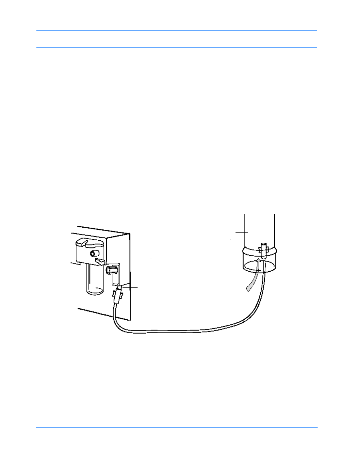
Room air
Hospital
scavenging
system
Gas
outlet
port
Connecting the Multigas Analyzer to a Scavenging System
To prevent pollution of the operating room, the gas sample should be vented from the operating room. Connect
the gas outlet port of the multigas analyzer (refer to Figure 1-2 on page 1-4) to the hospital scavenging system
(or anesthesia machine), or return the gas to the patient circuit.
Caution:
Do not connect the multigas analyzer directly to a vacuum scavenging system. Strong scavenging
suction can change the operating pressure of the multigas analyzer and can cause inaccurate
readings or damage to the analyzer.
Scavenging Through the Hospital Scavenging System
• Connect an exhaust line to the gas outlet port on the module’s front panel
• Insert the other end of the line into the hospital scavenging system. Ensure that the ventilation tube
diameter is at least two to three times larger than the exhaust line.
Caution:
Only connect the scavenging line to an open scavenging system, where the gas is removed at
room pressure. Do not connect the multigas analyzer directly to a vacuum scavenging system.
Figure 2-12: Scavenging through hospital ventilation
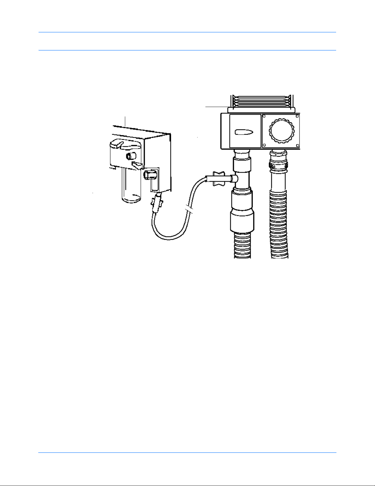
Scavenging Through the Anesthesia Machine Gas Scavenging System
Some anesthesia machines are equipped with an anesthesia gas scavenging system (AGSS). You may be
able to connect the multigas analyzer scavenging line directly to the AGSS. Refer to the documentation that
came with your anesthesia machine to determine if the scavenging line can be connected to the AGSS.
91518 Multigas Analyzer Service Manual 2-12
Page 23
Setup
Anesthesia
machine
Multigas Analyzer
Returning the Sample Gas to the Patient Circuit
The sample gas can also be returned to the patient breathing circuit. You may need an adapter to connect to
the patient breathing tubes.
Figure 2-13: Returning the sample gas to the patient circuit
91518 Multigas Analyzer Service Manual 2-13
Page 24

Setup
Power Up Verification
Prior to the initial use of a new analyzer (or a one that has just been serviced), verify the analyzer basic
performance using the following procedure. For equipment calibration, refer to Maintenance on page 4-1.
Note:
The 91518 Multigas Analyzer must be calibrated onsite prior to use and immediately after servicing.
Equipment Required
• Spacelabs Healthcare monitor
• SDLC cable
• Water trap
• Gas sampling line
Standalone Test
1 Insert a water trap (if one is not already present) into the analyzer front panel holder (ensure that the water
trap is not cracked.)
2 Verify that the monitor and analyzer are connected according to Multigas Setup on page 2-2.
3 Power OFF the multigas analyzer if the power is ON.
4 Power ON the monitor.
5 Power ON the analyzer.
6 Verify that the front panel ON/OFF button illuminates.
7 Verify that the pump starts within approximately 30 seconds.
8 Verify that the fan is operating.
9 Power OFF the analyzer.
System Test
1 Verify that the unit has passed the standalone test.
2 Connect the 91518 to a patient monitor as detailed in Multigas Setup on page 2-2.
3 Power ON the patient monitor.
4 Power ON the 91518.
Note:
The monitor must be powered on before the multigas analyzer.
5 Verify that the GAS parameter key and memory message appear on the monitor screen.
91518 Multigas Analyzer Service Manual 2-14
Page 25

Setup
6 Wait for at least two minutes for the gas sensors to warm up.
Note:
During warm up, other status messages may appear.
7 Connect the sampling line to the sampling line connector on the front of the water trap (refer to Figure 1-2
on page 1-4).
8 Breathe at least five breaths into the sample line.
9 Verify that a CO2 waveform and EtCO2 numerics appear on the monitor screen.
10 Verify that an O2 level of 16 to 23% appears.
Note:
The CO2 waveform and the EtCO2 and O2 numerics will take approximately 5 seconds before appearing
on the screen.
11 Remove the water trap. Verify that the LEAK DETECTED - Check System message appears on the monitor
screen within 20
12 Reinstall the water trap.
13 Verify that the leak detected message disappears.
If the water trap is not reinstalled within 40 seconds, the pump will shut off. To restart the sequence:
seconds.
a Touch GAS.
b Touch RESUME SAMPLING
c Touch YES.
14 Hold a finger over the water trap input (or pinch shut the sample line) to block air flow. Verify that the
message OCCLUSION - Check System appears on the monitor screen within 30
seconds.
91518 Multigas Analyzer Service Manual 2-15
Page 26

Page 27
Theory
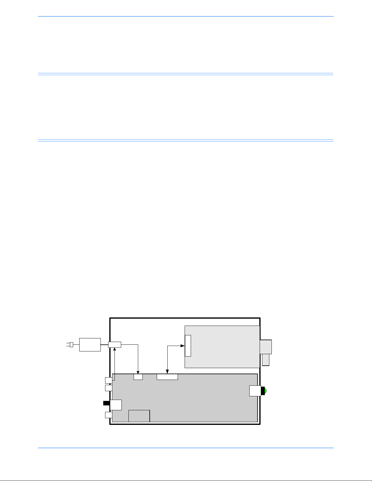
Interface
& Power PCBA
Multigas Module
Rear
SDLC_26-pin
SDLC_9-pin
PD Dev.
Ports
AC
BRICK
DC in
I/O
I/O
Serial / USB
Debug
DC
Serial / Pwr / cntl
Switch
Switch
/LED
AC
Input
Power
On
Gas
Sampling
Front
SDLC Termination
Switch
Contents
Overview. . . . . . . . . . . . . . . . . . . . . . . . . . . . . . . . . . . . . . . . . . . . . . . . . . . . . . . . . . . . . . . . . . . . . . . . . . . . . . .1
Interface PCBA . . . . . . . . . . . . . . . . . . . . . . . . . . . . . . . . . . . . . . . . . . . . . . . . . . . . . . . . . . . . . . . . . . . . . . . . . .3
Gas Analyzer Unit. . . . . . . . . . . . . . . . . . . . . . . . . . . . . . . . . . . . . . . . . . . . . . . . . . . . . . . . . . . . . . . . . . . . . . . .4
Oxygen Measuring Unit . . . . . . . . . . . . . . . . . . . . . . . . . . . . . . . . . . . . . . . . . . . . . . . . . . . . . . . . . . . . . . . . . . .9
Overview
The 91518 Multigas Analyzer is a side stream gas analyzer, measuring real time concentrations of O2, CO2,
N
O and anesthetic agents (halothane, enflurane, isoflurane, desflurane and sevoflurane).
2
The interface PCBA communicates through a two-way SDLC connection to the Spacelabs Healthcare monitor.
Warning:
If any halogenated anesthetic agent other than halothane, isoflurane, enflurane, desflurane, or
sevoflurane is present, it will be misidentified and/or will interfere with the reported anesthetic
agent concentrations.
Caution:
• When administering anesthetic agents, incorrect agent identification may occur when a mixture
of sevoflurane and enflurane occur in the sample circuit.
• When administering anesthetic agents, always verify your anesthetic vaporizer setting.
Note:
The 91518 Multigas Analyzer automatically identifies which agent is detected, but it cannot measure more
than one agent at a time.
91518 Multigas Analyzer Service Manual 3-1
Figure 3-1: 91518 Product overview block diagram
Page 28
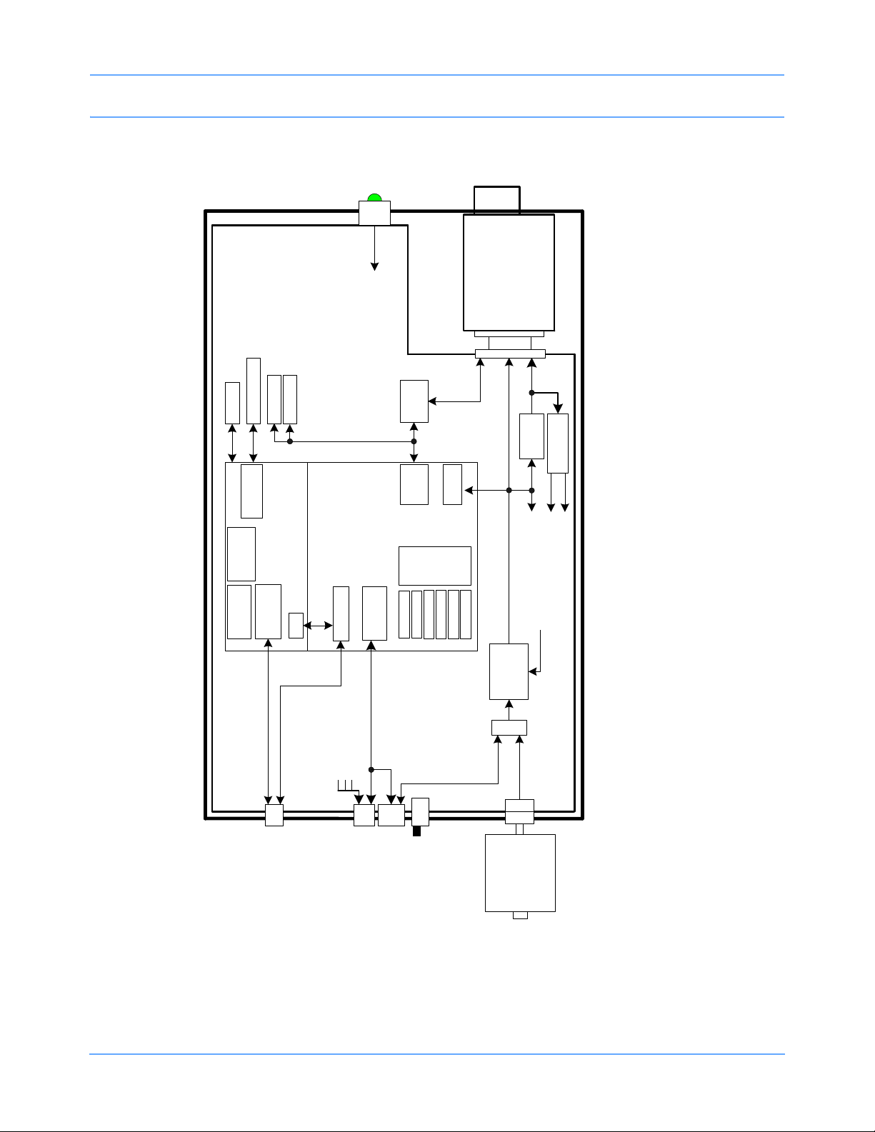
Multigas
Module
91518 Interface/Power PCBA
RS485
Xcvr
SDLC_9-pin
Serial / USB
Debug
BDM
Sniff1
Sniff 2
Ethernet
USB
Power
Switch
& LED
AC
input
DC-DC
Conv.
Power Path
Control
+9-18V to
+5V DC-
DC conv.
+18V
+18V
SDLC_26-pin
+5VDC
+/-15VDC
+5VDC
RS485
Ethernet
Controller
RS232
Xcvr
LED
indicators
Test
Switches
USB Xcvr
SDLC
Xcvr
Reset
MCU
RAM
Flash
eeprom
S/N rom
pcb ID
config
UART
Test /
Debug
Brick
supply
100-250VAC /
18.6 - 21V
(40W)
Interface
Core
Gas
Sampling
SW
SDLC
Termination
Switch
Power
On/Off
Power
On/Off
REAR FRONT
Regulators
PO_+5V
PO_+12V
PO_-12V
PO_+5V
PO_+12V
PO_-12V
SDLC
Theory
91518 Multigas Analyzer Service Manual 3-2
Figure 3-2: 91518 Detailed block diagram
Page 29

Theory
Interface PCBA
The interface PCBA (P/N 670-1319-xx) provides power to and controls the gas analyzer unit. The interface
PCBA is responsible for the two-way SDLC communication link with the Spacelabs Healthcare monitor. The
interface PCBA transmits processed data from the gas module to the monitor for display and recording.
Main CPU (MCU)
A Motorola MPC850 is the main CPU on the board.
EEPROM Circuit
The EEPROM stores configuration and setup information.
Serial Number IC Circuit
A serial number is available to be read by the MCU and then passed onto the host monitor upon demand. The
one-wire interface provides power through the pull-up resistor to the S/N IC. Data is bi-directional over this line.
This has no significance when replacing the PCBAs.
PCB Version Detection
The PCB codes the board version by selectively connecting each of the six lines either Hi or Lo, to form an ID
code. This is read and used by the software and passed to the host monitor upon demand.
Reset Circuit
A power-ON reset circuit provides a reset while the ISO_3.3V_CPU is coming up. The reset continues for an
additional 180 msec after the supply has reached the 3.0 V level or higher. If the supply drops below this level,
the circuit will again reset and reinitialize the 180 msec timer. Power Fail is implemented by monitoring the
+5 V supply and issuing a non-maskable interrupt (NMI) to the processor when the power supply goes low.
Data Lines - Power-Up Reset Configuration
During /HRESET, the MCU configuration is set by reading the data lines. /HRESET occurs at analyzer power
ON or reset.
Power Fault Detection
A low voltage fault on incoming ±12 V power supplies is determined by a pair of comparator circuits that
compare a divided-down sample of each supply to the reference voltage. When a fault occurs, an interrupt is
sent to the MCU.
91518 Multigas Analyzer Service Manual 3-3
Page 30

Theory
Memory Circuits (RAM and Flash ROM)
The memory circuits provide program memory for the MCU. The RAM is used for loading the software program
and data. The flash ROM is used for storing the software program.
SDLC Interface
The 91518 Multigas Analyzer communicates with the Spacelabs Healthcare monitor using a SDLC interface
that is common between all current Spacelabs Healthcare monitors and modules. The Multigas Analyzer can
use both 9-pin and 26-pin SDLC cables, depending on the Spacelabs monitor that is used. Refer to Multigas
Setup on page 2-2.
Test Indicator LEDs Circuit (Factory-Use Only)
The LED indicators are used for testing. Refer to Troubleshooting on page 5-1.
Gas Analyzer Unit
The OEM gas analyzer unit (P/N 010-1651-00) is a discrete device that measures the concentrations of gases.
Anesthetic agents or mixtures of two anesthetic agents are automatically identified and concentrations of the
identified agents are measured. The analyzer also detects mixtures of more than two agents and issues a
AGENT MIX message.
The gas analyzer unit consists of:
• Gas sampling system
• Gas measuring unit
• OM measuring unit
• CPU board
• OM board
Gas Sampling System
The sampling system takes care of drawing a gas sample into the analyzers at a fixed rate. The gas sampling
system samples the measured air to the analyzer and removes water and impurities from it. A sampling line is
connected to the water trap. The pump draws gas through the sampling line into the gas measuring unit. After
the gas measurements, the gas is exhausted through the sample gas out connector.
A larger pressure difference makes the deformations of the gas concentration curves less sensitive to high
variations of the airway pressures.
91518 Multigas Analyzer Service Manual 3-4
Page 31

Theory
D-fend Water Trap
The gas sample is drawn through a sampling line. The gas then enters the analyzer through the water trap,
where it is divided into two flows, a main flow and a side flow.
The main flow enters the analyzers and is separated from the patient side by a hydrophobic filter. The side flow
creates a slight subatmospheric pressure within the D-fend water trap, which causes fluid removed by the
hydrophobic filter to collect in the bottle.
Zero Valve and Absorber
The main flow passes through a magnetic valve before proceeding to the analyzers. This valve is activated to
establish the zero points for the gas measuring unit and the oxygen measuring unit. When the valve is
activated, room air is drawn through the absorber into the internal system and the gas sensors. Paralyme is
used as an absorbent.
Nafion Tube s
A nafion tube is used between the water trap and the zero valve to balance the sample gas humidity with that
of ambient air. The tube will prevent errors caused by the effect of water vapor on gas partial pressure when
humid gases are measured after calibration with dry gases.
Another nafion tube is used between the absorber and the pneumatic unit to prevent humidity caused by
absorption of CO
.
2
Gas Analyzers
After flowing through the zero valve and nafion tube, the gas flows through the gas measurement and oxygen
measurement (OM) units. The oxygen sensor has two inputs. One input accepts the main flow, and the other
draws in room air for reference, from the Ref port. Both gas flows exit from a single port.
Sample Flow Differential Pressure Transducer
The sample flow differential pressure transducer measures pressure drops across the OM inlet restrictor and
calculates the sample flow from the pressure difference.
Working Pressure Transducer
The working pressure transducer measures absolute working pressure between the gas measurement unit
and OM unit.
Pneumatic Unit
The pneumatic unit contains a zeroing valve, an occlusion valve, and tubing connections. A series of restrictors
and chambers forms a pneumatic filter that prevents pressure oscillations from the pump from reaching the
measuring units. The occlusion valve connection to room air includes a dust filter, and the zero valve
connection to room air includes an absorber.
Connection Block
The connection block contains a sample gas outlet connector and OM unit reference gas inlet (Ref). The inlet
is equipped with a dust filter.
91518 Multigas Analyzer Service Manual 3-5
Page 32

Theory
To Ref gas port
Occlusion Valve
The occlusion valve is activated when the sampling becomes occluded. The main flow is then diverted to the
side flow of the D-fend water trap, to remove the occlusion.
Sampling Pump and Damping Chamber
The gas sampling pump is a membrane pump that is run by a brushless DC motor. The sample flow is
measured with a differential pressure transducer across a known restriction. The motor is automatically
controlled to maintain a constant flow, even when the D-fend water starts to become occluded. The pump also
enables use of sampling lines of varying lengths and diameters. The damping chamber is used to even out the
pulsating flow and to silence the exhaust flow.
Note:
The flow is never reversed toward the patient.
Figure 3-3: Gas sampling system
91518 Multigas Analyzer Service Manual 3-6
Page 33

Theory
Figure 3-4: Gas tubing layout
Gas Measuring Unit
The gas measuring unit is a nondispersive infrared analyzer, measuring absorption of the gas sample (CO2,
N
O, halothane, enflurane, isoflurane, desflurane, and sevoflurane) at seven infrared wavelengths, which are
2
selected using optical narrow band filters. The infrared radiation detectors are thermopiles.
Figure 3-5: Gas analyzer in principle
Concentrations of CO2 and N2O are calculated from absorption measured at 3 to 5 µm (refer to Figure 3-6 on
page 3-8).
91518 Multigas Analyzer Service Manual 3-7
Page 34

Theory
Figure 3-6: CO2 and N2O absorbance
Identification of anesthetic agents and the calculation of their concentrations is performed by measuring
absorptions at five wavelengths in the 8 to 9 µm band (Figure 3-7) and solving the concentrations from a set of
five equations.
The measuring accuracy is achieved using numerous software compensations. The compensation parameters
are determined individually for each gas measuring unit during the factory calibration.
Figure 3-7: Infrared absorbance of anesthetic agents
The infrared radiation source is a 4-W filament, surrounded by thermal isolation. The lamp unit is gas tight. A
hole in the isolation allows the radiation to pass into to a 4-mm conical measuring chamber.
From the measuring chamber, the infrared radiation passes into seven tubular light guides with a reflective
inner surface. A thermopile detector with an optical filter is located at the other end of each light guide.
91518 Multigas Analyzer Service Manual 3-8
Page 35

Theory
The isothermal analyzer bench contains a temperature sensor that measures the temperature of the gas
sample, the optical filters, and the detectors. A pressure sensor measures the pressure of the gas sample.
The temperature sensor measures the gas measuring units’ temperature. It is used for temperature
compensation.
The gas measuring unit includes a TPX board located at the end of the unit. Its function is to connect the seven
thermopile signals and the temperature sensor signal to the CPU board.
Figure 3-8: Gas analyzing unit
Oxygen Measuring Unit
Oxygen concentration is measured with a paramagnetic oxygen sensor.
The sensor uses a differential pressure transducer to compare the pressure gradient produced when reference
and sample input gases are exposed to an oscillating magnetic field.
The oxygen measurement is based on paramagnetic susceptibility. The gas and the reference gas, which
usually is room air, are conducted into a gap with an electromagnet. A strong magnetic field switched on and
off at a frequency of approximately 165 Hz.
An alternating differential pressure is generated between the sample and reference inputs, due to magnetic
forces acting on the oxygen molecules in a magnetic field gradient.
The pressure is measured with a sensitive differential transducer. The transducer is rectified with a
synchronous detector and amplified to produce a DC voltage proportional to the oxygen partial pressure
difference of the two gases.
CPU board
The CPU board contains the processor and memories and analog-digital converters that are common to the
whole multigas analyzer. The CPU board also contains the preamplifiers for the TPX sensor and the drivers for
valves, fan, pump, and lamp. The multigas analyzer is connected to the analyzer bus through a RS-485 serial
channel.
91518 Multigas Analyzer Service Manual 3-9
Page 36

Theory
Figure 3-9: Signal processing
Figure 3-10: Control logic
91518 Multigas Analyzer Service Manual 3-10
Page 37

OM board
Theory
Figure 3-11: Calibration data stored in EEPROM
The oxygen measuring board contains the specific electronics for the oxygen sensor. The sample flow
measurement system and sampling system pressure sensors are on this board. It also contains EEPROMs
that store the calibration data for both the gas measuring and OM sensors.
91518 Multigas Analyzer Service Manual 3-11
Page 38

Page 39

Maintenance
Contents
Overview. . . . . . . . . . . . . . . . . . . . . . . . . . . . . . . . . . . . . . . . . . . . . . . . . . . . . . . . . . . . . . . . . . . . . . . . . . . . . . .1
Preventive Maintenance . . . . . . . . . . . . . . . . . . . . . . . . . . . . . . . . . . . . . . . . . . . . . . . . . . . . . . . . . . . . . . . . . . .2
Corrective Maintenance . . . . . . . . . . . . . . . . . . . . . . . . . . . . . . . . . . . . . . . . . . . . . . . . . . . . . . . . . . . . . . . . . .16
Disassembly and FRU Replacement . . . . . . . . . . . . . . . . . . . . . . . . . . . . . . . . . . . . . . . . . . . . . . . . . . . . . . . .24
Overview
Field service of this unit is limited to functional checks, cleaning, updating the interface software, replacement
of certain items during preventive maintenance, and replacement of the interface PCBA, the gas unit (OEM
gas module), and power switch.
Only trained personnel with appropriate equipment should perform the tests and repairs outlined in this
chapter.
Perform a functional check before starting preventive maintenance, to identify any issues requiring corrective
maintenance. A functional check should also be performed after the preventive maintenance procedure.
Perform a functional check after replacing any item during the corrective maintenance procedure.
Caution:
• Observe precautions for handling electrostatic-sensitive devices!
• Cleaning, preventive maintenance, and safety checks should be performed annually and
following any product disassembly/assembly. Preventive maintenance and safety checks must
be performed by trained personnel only.
Note:
• Never touch electrostatic-sensitive electronic components without following proper anti-static
procedures, including the use of an ESD wrist band and mat. An electrostatic discharge from your
fingers can permanently damage electronic components.
• All static-sensitive electronic components are packaged in static-shielding bags. Retain the bag for
repackaging the component, should you need to store it or return it to Spacelabs Healthcare for any
reason.
91518 Multigas Analyzer Service Manual 4-1
Page 40

Maintenance
Preventive Maintenance
If the multigas analyzer has been damaged in any way, check it for proper operation, and verify the accuracy of
its measurements.
A field service engineer should inspect the 91518 for acceptable performance at 12-month intervals, or at an
interval determined to be appropriate by an effective risk-based equipment management program established
by the hospital.
Hardware/Mechanical Check
Verify the following:
• The unit is clean.
• All screws are tight.
• The connector pins are not damaged.
• The case is not damaged.
Functional Performance Check
Note:
When the Multigas analyzer is initially connected to the power source, the analyzer will power ON. If the
analyzer does not power ON, press and hold the blue power button until the analyzer powers ON.
Before powering the multigas analyzer ON, make sure it is connected to a bedside monitor. The bedside
monitor must be powered ON prior to powering ON the multigas analyzer. Press the blue power ON/OFF
button located on the front of the multigas analyzer.
When you first power ON a properly installed multigas analyzer, the center of the power-ON button illuminates.
Within 30 seconds, the bedside monitor displays the GAS parameter key to the right of a flat waveform.
If this does not occur, verify that the power ON/OFF button is pressed and illuminated. The multigas analyzer
must be connected to an AC power outlet. Check that the SDLC switch on the back panel of the multigas
analyzer is in the correct position. Verify that the appropriate SDLC cable and terminator are connected to the
monitor. If the monitor or the module housing has an SDLC switch, check that the switch is in the correct
position. If the GAS parameter key does not display on the monitor, power OFF the multigas analyzer, and
then power OFF the monitor. Power ON the monitor again, and then power ON the multigas analyzer again.
Caution:
• The warm-up period for the multigas analyzer is less than two minutes for CO2, O2, and N2O,
and up to five minutes for anesthetic agents. The multigas analyzer reaches full accuracy after
30
minutes. You may use the multigas analyzer prior to full warm-up, but be aware of possible
inaccuracies in gas analysis.
• When the multigas analyzer is powered ON, all default settings will be re-established. Any
modifications made to the default settings (alarm limits, text display, etc.) prior to interruption
of power will be lost.
Check and verify that the D-fend water trap is empty. Spacelabs Healthcare recommends the disposal of the
water trap when full and between patients.
91518 Multigas Analyzer Service Manual 4-2
Page 41

Maintenance
If the water trap is not empty, follow the hospital safety procedures for handling possibly contaminated
material, and replace the water trap (refer to D-fend Water Trap Replacement on page 4-4).
Warning:
The used water trap may contain hazardous fluids and should be disposed of in accordance with
hospital procedures.
Initialization
When the multigas analyzer is powered ON, the message SENSOR WARMING UP will display for up to two
minutes, depending on the temperature of the multigas analyzer bench. Within two minutes, the SENSOR
WARMING UP message is replaced by the AGENT WARMING UP message on the prompt line. The AGENT
WARMING UP message will remain on the prompt line for up to three minutes.
The CO
waveform will be available only when the SENSOR WARMING UP message has disappeared.
2
After the warm-up periods, the GAS - SENSOR STABILIZING message displays on the prompt line for
approximately 30 minutes.
After the gas sensor has warmed up, the SENSOR WARMING UP message disappears, and the message
AUTO ZERO IN PROGRESS displays. A flat waveform displays at the zero baseline during zero calibrations.
During the warm-up periods or stabilization period, the multigas analyzer may perform one or more zero
calibrations.
Figure 4-1: Gas sampling line and gas sampling tee
1 After the SENSOR WARMING UP message has disappeared, and zeroing is not in progress, breathe
through the sampling tee for five slow breaths. If you don’t want to make contact with the sampling tee, cup
the tee in curled fingers, and breathe through your fist.
2 Verify that the waveform rises and falls accordingly. The numerics should display FiO2, FeO2, I CO2, and
ETCO
values. For the rest of the parameters question marks will display.
2
This completes the functional performance check. If the check passes, proceed with the preventive
maintenance. If the check fails, corrective maintenance is necessary.
91518 Multigas Analyzer Service Manual 4-3
Page 42

Maintenance
Replacing the Fan Air Filter
Note:
Depending upon the hospital environment, the air filter may need to be cleaned more frequently than
specified. It is recommended that, initially, hospitals inspect the air filter at monthly intervals until an
appropriate cleaning cycle can be established.
To replace the fan air filter:
1 Remove the filter cover from the front of the 91518 (refer to Figure 4-2 on page 4-4) using a small, flat
screwdriver.
2 Replace the filter with a new one, or clean the existing one by washing it with water and mild soap.
3 After the cleaned filter has dried, reinstall it.
4 Reinstall the fan filter cover.
5 Verify that fan is working properly and is drawing air into the unit.
Figure 4-2: Fan air filter
D-fend Water Trap Replacement
Warning:
The used water trap may contain hazardous fluids and should be disposed of in accordance with
hospital procedures.
To replace the D-fend Water Trap:
1 Twist the gas sampling line counter-clockwise at the input port to remove the sampling line from the D-fend
water trap.
2 Check and verify that the D-fend water trap is empty. Dispose of the water trap when full and between
patients.
3 If the water trap is not empty, follow the hospital safety procedures for handling possible contaminated
material.
91518 Multigas Analyzer Service Manual 4-4
Page 43

Maintenance
4 Remove the water trap by pressing the release lever on the right side of the water trap. Pull the water trap
away from its recess.
5 Discard the water trap according to hospital policies.
6 Open the D-fend package and remove the water container by pulling it away from the D-fend body with a
slight twisting motion.
7 Examine the water container’s O-rings to verify that there are no cracks or cuts.
8 Examine the D-fend ports that slip over the front panel connection posts, and verify that the front panel
chambers are smooth and have no slivers or burrs.
9 Press the water container into the D-fend, and press the D-fend into its recessed area on the front panel
until it is latched.
D-fend Connection O-Ring Replacement
An O-ring on each side of the connection post mates with the D-fend water trap. The O-rings can be removed.
To remove the O-rings:
1 Use a hooked dental pick or similar instrument (refer to Figure 4-3) to remove the O-rings from the posts.
Figure 4-3: Removing O-rings
To replace the O-rings:
1 Position the gas analyzer face up.
2 Lay the replacement O-ring on top of the connection post, and press the O-ring onto the post using finger
pressure. Or, position one edge of the O-ring onto the post groove using small, curved needle nose pliers
or tweezers, place a finger over the edge to keep it in the groove, then use you finger to roll the O-ring over
the top of the post.
3 Visually inspect the installation to make sure the O-ring is in the groove, and is not distorted (refer to
Figure 4-4).
91518 Multigas Analyzer Service Manual 4-5
Page 44

Maintenance
Figure 4-4: O-rings correctly seated in post grooves
Reference Gas Block Replacement
The reference gas connection block and filter is located to the right of the water trap.
To replace the reference gas connection block:
1 Peel off the label (; refer to Figure 4-5) that covers the screw, and then remove the screw.
Figure 4-5: Reference gas block label
Note:
A small O-ring is located between the filter unit and the front panel.
The filter element is sealed inside the block. Replacing the filter requires replacement of the entire block. There
is no replaceable filter in the block.
2 Install the new O-ring in the recess of the block, and carefully align the replacement block with the front
panel.
91518 Multigas Analyzer Service Manual 4-6
Page 45

Maintenance
3 Tighten the screw.
4 Apply the new Ref. Gas label.
Figure 4-6: Reference gas block assembly
Gas Unit Disassembly
The disassembly of the gas unit is necessary for the replacement of the pneumatic block filter, the nafion
tubing, and the absorber.
Caution:
Observe precautions for handling electrostatic-sensitive devices!
Note:
• Never touch electrostatic-sensitive electronic components without following proper anti-static
procedures, including the use of an ESD wrist band and mat. An electrostatic discharge from your
fingers can permanently damage electronic components.
• All static-sensitive electronic components are packaged in static-shielding bags. Retain the bag for
repackaging the component, should you need to store it or return it to Spacelabs Healthcare for any
reason.
To disassemble the gas unit:
1 Remove any cables from the back of the enclosure.
2 Unfasten the captive fastener (; Figure 4-7) in the middle of the right side rear panel. Remove the screws
(; Figure 4-7) securing the rear panel to the chassis enclosure. Retain the screws.
91518 Multigas Analyzer Service Manual 4-7
Page 46

Maintenance
Figure 4-7: Rear panel fastener and screws
3 Remove the rear panel from the chassis by pulling from the captive fastener straight back until the guide
pins clear both holes in the back of the unit handle.
4 Disconnect the gas unit connector cable by unfastening the cable’s captive screws
(Figure 4-8). Unplug the connector and route the cable to the left, away from the unit’s cavity in the chassis.
Figure 4-8: Connector cable
5 Remove the gas unit from the chassis by pulling straight back on the handle until the gas unit clears the
enclosure.
6 Remove the handle from the gas bench.
91518 Multigas Analyzer Service Manual 4-8
Page 47

Maintenance
7 Unfasten and remove the screws that secure the handle to the gas bench. Retain the screws.
Figure 4-9: Removing the handle from the gas bench
8 Grasp the front of the gas unit, and with the other hand, pull the metal case straight back and off. Set aside
the case, handle, and screws.
Figure 4-10: Separating the gas unit from the case
Assembly is the reverse of disassembly.
A functional check should be performed after the completion of the preventive maintenance procedure.
91518 Multigas Analyzer Service Manual 4-9
Page 48

Maintenance
Note:
There is a two-position dip switch located on the board edge near the end of the CPU board used with the
EEPROMs. It is shown in the normal operating position in
maintenance to ensure that the switch positions are not changed.
Figure 4-11: Dip switches, normal operating position
Figure 4-11. Be careful during preventive
Pneumatic Block Filter Replacement
To replace the pneumatic block filter:
1 Disassemble the gas unit according to Gas Unit Disassembly on page 4-7. Place the gas unit on an
anti-static mat with the pneumatic block and nafion tubing side facing up.
2 Remove the small Phillips head screw holding the filter restraint (refer to Figure 4-12). Use a needle nosed
pliers or tweezers to lift the filter restraint away from the block.
91518 Multigas Analyzer Service Manual 4-10
Page 49

Maintenance
Figure 4-12: Removing the filter restraint
3 Turn the gas unit over. The filter element should fall out. If it does not fall out, lightly tap on the side of the
pneumatic block to dislodge it. There is an O-ring on the bottom side of the filter element that may also fall
out.
4 Turn the gas unit over again.
5 Examine the O-ring. Unless it is severely damaged, place it back in the pneumatic block. The O-ring is used
as a spacer, and provides no seal.
6 Place the new filter element in the pneumatic block. Insert the filter element restraint in the recessed area,
and replace the screw. Do not overtighten the screw.
91518 Multigas Analyzer Service Manual 4-11
Page 50

Maintenance
Nafion Tubing Replacement
Follow the hospital safety procedures for handling possibly contaminated material.
1 Place the gas unit on an anti-static mat with the nafion tubing facing up. Refer to Figure 4-13, and examine
the routing of the Nafion tubing. There are two pieces of the nafion tubing of the same length arranged with
one oval loop laying inside another oval loop.
Figure 4-13: Nafion tubing routing
2 With your fingers or with needle-nosed pliers, lift the inside tubing loop away from the metal bracket fingers
and gently pull the end barb out of the short tube attached to the absorber (refer
page 4-13). Gently pull the other end barb out of the short tube attached to the pneumatic block G port.
91518 Multigas Analyzer Service Manual 4-12
to Figure 4-14 on
Page 51

Maintenance
Figure 4-14: Disconnecting the nafion tubing
3 Lift the remaining tubing loop away from the metal bracket fingers and gently pull the end barb from the short
tube on the pneumatic block port E.
4 Pull the other end barb from the short tube that connects to the small diameter tubing running to the front
panel water trap container.
5 Discard the two lengths of nafion tubing according to hospital policy.
Note:
• If the nafion tubing replacement is being performed as part of the preventive maintenance procedure,
proceed to
• If the nafion tubing replacement is being performed as part of the corrective maintenance procedure,
and the absorber is at least six months from replacement, install the new pieces of Nafion tubing.
Absorber Replacement on page 4-13.
Absorber Replacement
The absorber is marked with an expiration date. Before proceeding, verify that the new absorber from the
preventive maintenance or corrective maintenance kit has a minimum of one year to the expiration date.
To replace the absorber:
1 Follow the hospital safety procedures for handling possibly contaminated material.
2 Pull the end barb out of the short tube attached to the absorber (if not already disconnected as part of the
nafion tubing replacement procedure).
3 Remove the two bracket screws (; Figure 4-15 on page 4-14) near the ends of the absorber. Lift the
bracket slightly and pull out the free end of the absorber.
91518 Multigas Analyzer Service Manual 4-13
Page 52

Maintenance
4 With your fingers or with needle-nosed pliers, gently pull the short tubing off the captive end of the absorber,
being careful not to stress the inner small diameter tubing.
5 Lift the bracket and slip the absorber in position. Install the two bracket screws.
6 Install the nafion tubing barb into the short tube (; Figure 4-15) on the absorber.
Figure 4-15: Nafion tubing connected
Cleaning
Warning:
• Use only recommended cleaning solutions, or you may void the manufacturer’s warranty.
• Harsh chemical agents degrade plastics and will compromise the safety of the device.
• Disconnect the equipment from the patient and the electrical supply before cleaning.
• Do not allow liquid to enter the interior of the multigas analyzer or monitoring equipment.
• Do not immerse the equipment or cables in water or cleaning solutions.
• Do not autoclave.
To clean the exterior of monitoring equipment and cables:
• Prepare the cleaning solution according to the manufacturer’s instructions.
• Wet a clean cloth with the selected cleaning solution.
• Remove excess liquid from the cloth and squeeze dry.
91518 Multigas Analyzer Service Manual 4-14
Page 53

Maintenance
• Wipe exposed surfaces of the equipment and cables.
• Remove any soap residue by gently wiping with a clean damp cloth.
• Wipe dry with a clean dry cloth.
Use only the following recommended cleaning solutions:
• Mild soap and water solution
• U.S. Pharmacopoeia (USP) green soap
• Sodium hypochlorite solution (1:10 dilution of household chlorine bleach in water)
• Phenolic germicidal detergent (1% aqueous solution)
• Glutaraldehyde (2.4%) (Cidex)
• Isopropyl alcohol (70% solution
Note:
Over time, repeated use of a chlorine bleach solution may cause some colors to fade.
Tape adhesive can be removed with Spacelabs Healthcare adhesive tape remover pads (P/N 392196-001).
Questions and concerns about cleaning issues should be directed to a Spacelabs Healthcare field service
engineer.
Caution:
Do not allow liquid to enter the interior of the 91518 Multigas Analyzer. If this should occur, check
the unit for proper operation and verify its performance accuracy prior to reuse.
Disposable and reusable patient accessories are available for the 91518 Multigas Analyzer. Disposable
accessories are for single-patient use only and must not be sterilized or cleaned for reuse on other patients.
Refer to the instructions provided with each patient accessory to determine if the accessory may be cleaned
and reused on the same patient.
Reusable accessories can be used on multiple patients after cleaning and/or sterilizing. Refer to the
instructions provided with these accessories for details.
Instructions provided with patient accessories may contain warnings regarding their use. Read these
instructions carefully prior to use.
Note:
The Spacelabs Healthcare sampling lines are for single-patient use only. Cleaning deteriorates the
properties of the sampling line, resulting in slower response time and more frequent occlusions.
Software Updates
Software updates can only be performed by a Spacelabs Healthcare field service engineer. The 91518
Multigas Analyzer must be calibrated when it is installed at the site (refer to Power Up Verification on
page 2-14). Refer to Service Calibration Mode on page 4-16.
Caution:
The 91518 MUST BE CALIBRATED at a location within 50 mmHg (6.67 kPa) atmospheric pressure
of where the device will be used.
91518 Multigas Analyzer Service Manual 4-15
Page 54

Maintenance
Firmware Updates
When necessary, firmware updates to the 91518 Multigas Analyzer are made by PCBA replacement.
Corrective Maintenance
Corrective maintenance begins with initiating actions to determine the equipment’s state of functionality. This
usually begins with questioning the clinical user in the degree of equipment functionality and the type of
problem encountered.
Functional Performance Check
Part of the examination is a functional performance check.
Refer to Functional Performance Check on page 4-2, and perform the procedure. The functional performance
check is always performed before and after the preventive maintenance procedure, and before and after the
corrective maintenance procedure.
Service Calibration Mode
Warning:
The calibration gas used in these procedures contains an anesthetic agent that must be vented
away from users. You must either complete these procedures in a well-ventilated space or connect
the scavenge port and excess flow lines to an exhaust
hood or gas-scavenging system.
Gas Calibration
The calibration process utilizes a very specific and accurately proportioned mixture of anesthetic agent, N2O,
CO
, and either O2 or N2 against which the 91518 is standardized. The calibration gas is supplied in a canister
2
with a limited amount of gas.
When the calibration sequence begins, a detailed analysis of the incoming gas is performed. The 91518
software contains the exact numeric values for the various gases that are documented on the sample bottle.
Initially, the 91518 examines the contents of the measurement chamber for the specific signature of each gas
and compensates for any difference between the measured value and the expected value. These correction
factors are stored in non volatile memory for subsequent use.
Note:
The numeric values that are displayed following a successful calibration do not need to exactly match the
nominal values listed on the sample bottle. This is due to small ongoing variations in flow, pressure, and
temperature for both the source gas and the measurement chamber. However, if the initial error is larger
than 20%, a second calibration may be necessary to reduce the remaining error to insignificance.
When calibrating, it is recommended that you use a full bottle that has stabilized at a temperature of 21° to
32° C (70° to 90° F) for at least 24 hours.
Note:
Bottles that have been exposed to and have attained a temperature below 0° C (32° F) should never be
used for calibration due to the destructive nature of extremely cold temperatures on the gas mixture.
91518 Multigas Analyzer Service Manual 4-16
Page 55

Maintenance
Gas calibration uses the tee connector and gas flow meter configuration that is illustrated in
Figure 4-16 on page 4-18. The pressure regulator is set to provide a stable flow of calibration gases that is
greater than required by the 91518.
The excess calibration gas flow is directed through the side port of the tee. It is critical that the excess gas flow
be maintained through the flow meter at 20-50 ml/min to ensure that the gas flowing into the 91518 is not being
diluted by room air and preventing accurate calibration.
Equipment and Supplies Needed for Calibration
• Calibration Adapter Kit: P/N 025-0047-00
• Calibration Gas Mixture (5% Desflurane, 5.5% CO2, 43% N2O, 46.5% O2) (P/N 025-0047-00)
• 37" (94 cm) Polyurethane Tubing (used to cut 1" (2.54 cm) and 36" (91.4 cm)* tubing)
(P/N
166-0011-00)
• Tee Connector (P/N 214-0486-00)
• Male Luer Fitting* (P/N 214-0261-00) (used if the flow meter is equipped with 1/8 inch barb fittings. If
the flow meter has 1/16
and 1/16
• 7-foot (213 cm) Sample Line (P/N 162-0047-01)
• Gas Pressure Regulator (P/N 369009-002)
inch male luer fitting.)
inch barb fittings installed, substitute 36 inches 1/16" I.D. polyurethane tubing
• SDLC Cable, Tee (P/N 012-0175-xx)
• SDLC Terminator (P/N 012-0507-xx)
• Flow Meter, Brooks Model 1355 or equivalent (provide locally)
91518 Multigas Analyzer Service Manual 4-17
Page 56

Maintenance
gas pressure
1" (2.54 cm) polyurethane
flow meter
Brooks Model 1355 or
equivalent
91518 Multigas Analyzer
CAL gas cylinder
7' (2.13 m) blue tinted
to scavenging system
36" (91.4 cm) polyurethane
male luer fitting
sample line to
91518 water trap
input
regulator
or exhaust hood
tubing
from
scavenging port
tubing
To perform a gas calibration:
1 Perform the setup procedure and performance verification procedure.
2 Verify that the stabilization message has disappeared from the prompt line (the analyzer may take up to 30
minutes to fully warm up and stabilize).
3 Press the GAS key, then press the CAL key to open the Calibration Menu. Refer to
Figure 4-17 on page 4-20.
4 Press ZERO / YES to perform a zero calibration.
5 Connect the gas analyzer to the gas cylinder using the setup shown in Figure 4-16.
6 Touch the hidden SERVICE CAL key (one inch to the right of the ZERO key) five times.
7 Establish a gas flow which includes a gas overflow of 20 to 50 ml/min from the side port of the tee as read
on the flow meter (the pump rate should already be at the default value of 175
Note:
The 91518 must be powered on for 30 minutes to allow the internal temperatures to stabilize.
91518 Multigas Analyzer Service Manual 4-18
Figure 4-16: Gas calibration setup
ml/min).
Page 57

Maintenance
8 Watch the CO2 waveform line and all numeric values. When everything appears to be stable and the agent
is identified as DES, verify that the gas readings are as follows:
Table 1: Gas Readings
Calibration Gas
Bottle
Concentration
Required 91518 Indication
N2O 43% 39 – 47%
DES 5.0% 4.8 – 5.2%
O
CO
2
2
46.5%* 44 – 49%
5.5% 5.3 – 5.7%
* Although the gas bottle contains 46.5% O2, the 91518 reads O2 in whole number percentages.
9 If the displayed values of FiO2 do not fall within the range listed above after the completion of the gas
calibration, return to
step 3.
10 If the display values of N2O, DES, and CO2 do not fall within the ranges listed above, recalibration is
required. Touch CAL GAS. Recheck to ensure that the gas flow rate is correct and stable, then touch YES.
Wait for the span operation to complete. If the span is successful, the numeric values will reappear.
11 Verify that the gas values displayed are within the ranges provided in Table 1. If they are not correct, verify
that the excess gas flow rate is still within 20 to 50 ml/min. If the flow rate has diminished below the required
20 to 50
and read the values again. If the values are still outside the specified values as noted in
ml/min and the regulator valve is fully opened, replace the gas bottle, re-establish proper gas flow,
Table 1, repeat the
span procedures.
12 If the CAL GAS FAILED message appears, verify that the excess gas flow rate is still between 20 to
50 ml/min, then touch the monitor’s NORMAL SCREEN key and repeat the gas calibration procedures.
Note:
If the calibration fails, check the unit for leaks and/or a cracked water trap or a kinked hose.
13 Shut off the gas flow as soon as calibration is finished.
91518 Multigas Analyzer Service Manual 4-19
Page 58

Maintenance
GAS - SERVICE CAL ***WARNING*** The patient is not being monitored
LIMITS
ALARM
FREEZE
ON OFF
SETUP
PRINT
SERVICE
GAS - MAIN MENU
SUSPEND
SAMPLING
CAL
YES
NO
CAL
NEXT
PAG E
PRINT
PAG E
PREV
YES
NO
ZERO
CAL
Hidden key:
Touch five times
to display
SERVICE CAL menu
GAS - CALIBRATION MENU
GAS PAGE
SERVICE CAL Menu Keys
ZERO — touching this key leads to the ZERO confirmation menu. Pressing the YES key performs a zero.
CAL GAS — Touching this key leads to the CAL GAS confirmation menu. Pressing the YES key performs a
calibration of the agent, N
Spacelabs Healthcare calibration gas supply must be present throughout the entire procedure. After the gas
calibration is complete, compensation values will be stored in the nonvolatile memory (NVRAM). Pressing the
NO key will return to the Service Cal Mode menu.
If the gas calibration fails, the analyzer will display the CAL GAS FAILED message and will remain in this mode
until a successful calibration is completed or until the bench is turned OFF. When the calibration failed
message is displayed, touching the GAS key and then the NORMAL SCREEN key removes the message from
the waveform zone and stops the alarm tone. However, the message will continue to display on the monitor’s
prompt line. Whenever a span failure occurs, the previous calibration factors are not lost. The analyzer
continues to function and report the gas values, but the full accuracy of the values is not guaranteed. If the cal
gas span is successful, the analyzer will return to the numeric display mode.
The CAL GAS key is disabled whenever the pumps are stopped because of one of several general messages,
when the sampling is suspended, or when another span/calibration is in progress.
PREV PAGE Key — Cycles forward through the service menu pages.
NEXT PAGE Key — Cycles backward through the service menu pages.
PRINT PAGE Key — Sends a bitmap image of the Service Cal Mode menu to a recorder or system printer.
Figure 4-17: GAS - CALIBRATION menu
O, and CO2 sensors and displays the CAL GAS IN PROGRESS message. The
2
91518 Multigas Analyzer Service Manual 4-20
Page 59

Maintenance
SERVICE CAL Mode
The SERVICE CAL key is a hidden key about one inch to the right of the ZERO key. Touching the hidden
SERVICE CAL key five (5) times in a row will display the SERVICE CAL MODE menu. While in service
calibration mode, the patient is not being monitored, and the diagnostic (calibration) data values are displayed
and trended.
Figure 4-18: SERVICE CAL MODE menu, page 1
Figure 4-19: SERVICE CAL MODE menu, page 2
While in the SERVICE CAL MODE menu, the menu prompt line will display a warning indicating that the
patient is not being monitored, because:
• The monitor has switched to display the diagnostic (calibration) data values.
• The patient has been disconnected from the 91518 in order to supply calibration gases.
• The breath detection is disabled, and the displayed values are not based upon breath detection.
However, the waveform will continue to be displayed as an aid for determining steady gas flow, and the alarms
are NOT disabled.
The SERVICE CAL MODE menu is designed for use by qualified personnel, and may contain information
useful to a biomedical engineer, a field service engineer, or Spacelabs Healthcare product support. The
following information displays while in SERVICE CAL MODE:
CO2= xx mmHg — Instantaneous carbon dioxide data in mmHg
O2= xx% — Instantaneous O
data in percent
2
N2O= xx% — Instantaneous nitrous oxide data in percent
MAC= x.x — Instantaneous MAC value
AA-P= x.x% — Instantaneous primary agent data in percent
91518 Multigas Analyzer Service Manual 4-21
Page 60

Maintenance
BARO PRESSURE= xxx mmHg — Instantaneous barometric pressure in mmHg; < RANGE or > RANGE
displays when the barometric pressure is out of normal operating range (500 to 800 mmHg) (refer to Figure 4-20).
Figure 4-20: SERVICE CAL MODE menu, page 1, out of range displayed
CELL PRESSURE= xxx mmHg — Instantaneous cell pressure in mmHg
TPX Sensor Temp — Gas sensor temperature in °C
O2 Bench TEMP — Oxygen sensor temperature in °C
OEM CPU Temp — Gas module CPU temperature in °C
IF Boot Code, IF App Code, IF Table Code, FE Code — Respective interface (IF) version numbers
Module Options — Refers to the options enabled for the multigas analyzer
Monitor Type — Refers to the type of Spacelabs Healthcare monitor being used with the analyzer
IF, FE — Interface PCBA and front-end PCBA version numbers
General Error Status — Product support use only
Internal SW Status — A non-zero value indicates the analyzer requires factory service
Diagnostic Error Status — A non-zero value indicates the analyzer requires factory service
Gas flow Control Status — For factory/product support use only
OEM HW Status — For factory/product support use only
OEM Config — For factory/product support use only
Warmup — Sensor warm-up time in minutes and seconds
Stabilize — Sensor stabilization time in minutes and second
Agent Warmup — Agent warm-up time in minutes and second
IF Selftest Result — The interface board has reset; a value of 0 indicates a successful self-test
91518 Multigas Analyzer Service Manual 4-22
Page 61

Maintenance
Leak Check Test
The leak test is used to determine if the 91518 leaks by measuring the leak rate after applying pressure. The
91518 should not be in service during a leak test, and power should be disconnected from the unit.
To test for leaks in the 91518:
1 Install a D-fend water trap (P/N 717-0447-00) into the 91518.
2 Connect the manometer and bulb valve, using a T-connector, to the 91518 at the port on the water trap.
3 Use your fingers to cover the Ref. and exhaust ports, to prevent leaking.
4 Pump the system pressure to 180 mmHg with the bulb assembly, and then close the bulb valve.
5 Pinch the hose closed with a hemostat.
6 Verify that the leak rate is less than 10 mmHg per minute.
7 Remove the test setup.
If the leak test fails:
1 Change the water trap, and repeat steps 1 through 6.
2 Change the gas filter, and repeat steps 1 through 6.
3 Inspect all internal tubing and pneumatics for damage or wear, and replace as needed. Repeat steps 1
through 6.
Figure 4-21: 91518 leak test configuration
91518 Multigas Analyzer Service Manual 4-23
Page 62

Maintenance
Disassembly and FRU Replacement
Interface PCBA Replacement
To replace the PCBA interface:
1 Remove all cables from the rear panel.
2 Unfasten the captive fastener in the middle of the gas unit rear panel and remove the screws securing the
rear panel to the chassis enclosure. Save the screws.
3 Remove the rear panel from the chassis by pulling from the captive fastener straight back until the guide
pins clear both holes in the back of the gas unit handle.
4 Disconnect the cable plugged into the gas unit connector by unfastening the cable’s captive screws. Unplug
the connector and route the cable to the left, away from the gas unit cavity in the chassis.
5 Remove the four screws fastening the PCBA rear panel to the chassis enclosure.
6 By holding the small handle at the left of the rear panel, pull the PCBA/rear panel assembly halfway out of
the enclosure to expose the cable assembly connected at the center top of the PCBA. Unplug the cable
assembly from the PCBA right angle connector, then remove the PCBA/rear panel assembly from the
enclosure.
7 Unplug the (looped) short cable behind the rear panel from the PCBA.
8 Remove all six screwlocks holding the rear panel to the PCBA interface. Save the rear panel and
screwlocks.
9 Attach the rear panel to the new replacement PCBA interface using the screwlocks. Do not overtighten. Plug
the short looped cable into the PCBA connector.
10 Install the PCBA/rear panel assembly into the chassis enclosure by aligning the top and edges of the board
with the card guides in the enclosure. Push the assembly halfway in.
11 Plug the four-wire cable assembly into the top-center right-angle connector on the PCBA. Route the flat
ribbon cable tethered to PCBA interface within the enclosure, being careful to not kink the cable with the
surrounded hardware. Plug the cable into the gas bench connector. Fasten the captive screws. Do not
overtighten.
12 Secure the PCBA/rear panel assembly to the enclosure using four 6-32 × 1/4-inch screws. Do not
overtighten.
13 Install the gas bench rear panel to the chassis, aligning the guide pins with the clearance holes in the gas
bench handle.
14 Push the rear panel against the mating surfaces in the chassis. Secure the rear panel with four
6-32
× 1/4-inch screws. Tighten the captive screw. Do not overtighten the screws.
Replacement of the PCBA interface is complete.
91518 Multigas Analyzer Service Manual 4-24
Page 63

Maintenance
Gas Unit Replacement
Use the following steps to replace the gas unit:
1 Remove any cable(s) from the back of the enclosure.
2 Unfasten the captive fastener in the middle of the right side rear panel. Remove the screws securing the
rear panel to the chassis enclosure. Save the screws.
3 Remove the rear panel from the chassis by pulling from the captive fastener straight back until the guide
pins clear both holes in the back of the gas unit handle.
4 Disconnect the gas unit connector cable by unfastening the cable’s captive screws. Unplug the connector
and route the cable to the left, away from the gas unit cavity in the chassis.
5 Remove the gas unit from the chassis by pulling straight back on the handle until the gas unit clears the
enclosure.
6 Insert the new gas unit into the chassis, guiding the front nose through the front opening.
7 Install the ribbon connector and tighten the screws.
8 Reinstall the rear panel, guiding the panel pins into the handle holes. Finger tighten the captive fastener in
the center of the panel.
9 Align the rear panel corner screw holes to the chassis, and install the four screws.
10 Perform a gas calibration. Refer to Gas Calibration on page 4-16.
Note:
Perform a functional check after replacing the gas unit.
Power Switch Assembly Replacement
Use the following steps to replace the power switch assembly:
1 Remove all cables from the rear panel.
2 Unfasten the captive fastener in the middle of the gas unit rear panel and remove the screws securing the
rear panel to the chassis enclosure. Save the screws.
3 Remove the rear panel from the chassis by pulling from the captive fastener straight back until the guide
pins clear both holes in the back of the gas unit handle.
4 Disconnect the cable plugged into the gas unit connector by unfastening the cable’s captive screws. Unplug
the connector and route the cable to the left, away from the gas unit cavity in the chassis.
5 Remove the four screws fastening the PCBA (left side) rear panel to chassis enclosure.
6 By holding the small handle at the left of rear panel, pull the PCBA/rear panel assembly half way out of the
enclosure to expose the cable assembly connected at the center-top of the PCBA. Unplug the cable
assembly from the PCBA right-angle connector, then remove the PCBA/rear panel assembly entirely from
the enclosure.
7 Remove the four colored screws (with washer) from the top of the enclosure. Turn the enclosure over and
remove the colored screws and the screws fastening both the foot assemblies to the enclosure.
8 Set the enclosure on one of its sides with the bezel facing you. Hold the side cover from its back edges and
pull the side walls away from the chassis as you tilt the edges counterclockwise. Pull the side cover away
from the chassis. Repeat this step to remove the other side cover from the chassis.
91518 Multigas Analyzer Service Manual 4-25
Page 64

Maintenance
9 Remove the four screws holding the chassis to the back of the bezel. Disconnect the tethered cable from
the wire clip in the chassis. Remove the entire bezel assembly (tethered cable included) from the chassis.
Set the chassis aside and save the screws.
Figure 4-22: PCBA removal
10 Remove the four screws from the bezel assembly, then remove the bracket screws holding the ON/OFF
switch cable assembly. Save the bracket and screws.
Figure 4-23: PCBA removal
91518 Multigas Analyzer Service Manual 4-26
Page 65

Maintenance
11 Install the new ON/OFF switch cable assembly into the bezel opening, making sure the lettering on the
elastomer keypad is up (toward the bezel vents).
12 Replace the bracket on top of the PCBA (closed end up), aligning the guide pins in the bracket with the
PCBA holes. Fasten the screws lightly. Do not overtighten the screws.
13 Set the chassis down with the front end to the left and the rear to the right (with the PCBA cavity closer to
you). From the front end of the chassis, pass the connector end of the bezel assembly through the PCBA
cavity to the back of the chassis. Hold both ends of the cable and thread the middle of the cable through the
open end of the wire clip.
14 Using the alignment pins on the back of the bezel, align the chassis to the bezel.
Note:
The bezel opening must align with the larger cavity of the chassis. Fasten the screws to the bezel, then
torque the screws to 8 lb/in.
15 Set the chassis on its side with the bezel toward you (the top of the chassis to the right). Hold the left side
of the cover (with the open end toward the chassis and the grooved end toward the bezel). With one hand
on each vertical wall, pull the side walls slightly out, then slide the grooved end of the side cover in at an
angle, into the bezel edge and down against chassis side, until the side cover is even with the bezel edges.
16 Set chassis on its opposite side, with the bezel towards the assembly. Assemble the right side cover in the
same manner as the left side cover.
17 Lightly fasten the top surface of the side covers to the chassis using the four painted screws and their
washers. Repeat the step at the bottom of enclosure, through the two middle holes in the side covers.
18 Attach the feet to the bottom of the enclosure, fastening them lightly with four 8-32 × 7/8-inch screws. Do
not overtighten the screws.
19 Install the PCBA/rear panel assembly into the chassis enclosure by aligning the top and the board edges
with the card guides in the enclosure. Insert the assembly halfway.
20 Plug the four-wire cable assembly into the top-center right-angle connector on the PCBA. Carefully route
the flat ribbon cable tethered to the PCBA interface to avoid kinking it with surrounding hardware.
21 Secure the PCBA rear panel to the enclosure by using four 6-32 × 1/4-inch screws. Do not overtighten the
screws.
22 Hold the gas unit from the handle and install the gas unit (with the front top slanted surface up) into the cavity
in the back of enclosure. Keep the cable attached to the PCBA interface routed away from the gas unit cavity
and insert the gas unit until the front bottom surface of the gas unit is even with the recessed surface in the
enclosure front bezel.
23 Make sure flat ribbon cable (tethered to the PCBA) is properly routed, then plug the cable into the gas unit
connector. Do not overtighten the screws.
24 Install the gas unit rear panel to the chassis, aligning the guide pins with the clearance holes in the gas unit
handle.
25 Push the rear panel against the mating surfaces in the chassis. Secure the rear panel with
four
6-32 × 1/4-inch screws, then torque the screws to 8 lb/in. Tighten the captive screw. Do not overtighten
the screws.
Replacement of power switch assembly is complete.
91518 Multigas Analyzer Service Manual 4-27
Page 66

Page 67

Troubleshooting
Contents
Tools and Equipment . . . . . . . . . . . . . . . . . . . . . . . . . . . . . . . . . . . . . . . . . . . . . . . . . . . . . . . . . . . . . . . . . . . . .1
Problem Solving . . . . . . . . . . . . . . . . . . . . . . . . . . . . . . . . . . . . . . . . . . . . . . . . . . . . . . . . . . . . . . . . . . . . . . . . .1
Tools and Equipment
The following tools and equipment are needed for testing:
• Spacelabs Healthcare monitor
• 3 1/2 digit or better digital multimeter (DMM), Tek DM501A, or similar
• SDLC extender cable (P/N 175-0360-00)
Problem Solving
Before PCBA-level troubleshooting is initiated, first establish that there is a fault with the analyzer.
The 91518 Multigas Analyzer comes with some diagnostic capabilities. When certain error conditions are
detected, messages are displayed in the waveform zone on the monitor. Message text flashes to indicate that
there is a problem.
91518 Multigas Analyzer Service Manual 5-1
Page 68

Troubleshooting
Error Conditions and Status Messages
Clinical Situation Possible Cause Solution
Analyzer does not
sign ON
OCCLUSION Check system
-orOCCLUSION Check system
■ Defective hardware. ■ Open the multigas analyzer and
connect it to the Spacelabs
Healthcare monitor with an
extender cable. If no diagnostic
LEDs on the interface board are
illuminated:
• Check for power to the
multigas analyzer
• Check for +5 V at J1, pin 2 on
the interface board.
• Check for +12 V at J1, pin 11.
• For SDLC operation,
verify -12 V DC is present.
■ Replace the Interface PCBA
if the above conditions are
not met.
■ Flash memory programming
error, or defective software
on the interface board.
■ The sampling line is blocked. ■ Check the sampling line for
■ Contact a Spacelabs Healthcare
Field Service Engineer.
blockage or crimps, and replace
as necessary.
■ If the occlusion persists for a
period greater than
40 seconds, the pump will be
turned off, and the second
message will be displayed.
Leak Detected Check system
-orLeak Detected Check system
91518 Multigas Analyzer Service Manual 5-2
■ A leak is detected in the
sampling line.
■ If the condition persists for a
period greater than
40 seconds then the pump
will be turned off and the
second message will be
displayed.
■ Check the sampling line for
blockage or crimps, and replace
as necessary.
Page 69

Troubleshooting
Clinical Situation Possible Cause Solution
SAMPLING
SUSPENDED
Patient is not
monitored
SERVICE REQUIRED Send for repair
COMMUNICATION
LINK LOST - Service
required
-orCOMMUNICATION
DROP OUTS - Service
required
■ Defective hardware.
■ Multigas analyzer self-test
failure.
■ Invalid option programming.
■ Invalid or corrupt EEPROM
configurations
■ An internal communication
error was detected.
■ Check for power to the multigas
analyzer and the interface board
as follows:
• J501:
Pin 7-12 V ±0.50 V
Pin 10+12 V ±0.50 V
Pin 11+5 V ±0.25 V
• J720:
Pin 5-12 V ±0.50 V
Pin 7+3.3 V ±0.25 V
Pin 8+12 V ±0.25 V
Pin 9+5 V ±0.25 V
■ Contact a Spacelabs Healthcare
field service engineer
■ Troubleshoot multigas analyzer;
start by replacing OEM multigas
bench.
■ Return the multigas analyzer to
Spacelabs Healthcare for repair.
SERVICE CAL MODE Patient is not
monitored
NO BREATH
DETECTED
CAL GAS IN
PROGRESS
ZERO IN PROGRESS ■ A Zero calibration is in
91518 Multigas Analyzer Service Manual 5-3
■ Service Calibration menu is
displayed
■ Breaths are not detected for
a duration equal to the
APNEA timeout duration
■ CAL GAS calibration is in
progress.
progress.
■ Touch NORMAL SCREEN to exit
this mode.
■ Verify sensor is properly
connected to the patient.
Message will clear after three
breaths are detected, or the
ACKNOWLEDGE ALARM key is
touched.
■ Wait until CAL GAS calibration is
completed and the message
goes away.
■ Wait until Zero calibration is
completed and the message
goes away.
Page 70

Troubleshooting
Clinical Situation Possible Cause Solution
AUTO ZERO IN
PROGRESS
CAL GAS
INCOMPLETE sensor not ready
■ An automatic zero calibration
is in progress.
■ CAL GAS calibration was
unable to proceed because
the sensor is not ready.
■ Wait for the message to
disappear.
■ Test the multigas analyzer by
replacing the known good OEM
bench. If tests OK, return the
faulty OEM bench to Spacelabs
Healthcare for repair. If the good
OEM bench does not correct the
problem, troubleshoot the
multigas analyzer or return the
analyzer to Spacelabs
Healthcare for repair.
■ Wait for the message to
disappear.
■ Test the multigas analyzer by
replacing the known good OEM
bench. If tests OK, return the
faulty OEM bench to Spacelabs
Healthcare for repair. If the good
OEM bench does not correct the
problem, troubleshoot the
multigas analyzer or return the
Analyzer to Spacelabs
Healthcare for repair.
SERVICE REQUIRED ■ Invalid SysGen configuration
was detected.
■ An OEM software error was
detected
WARMING UP ■ The unit is self testing or
warming up.
AGENT WARMING UP ■ The Anesthetic Agent unit is
self testing or warming up.
CHECK OR REPLACE
WATER TRAP
■ There is no water trap
installed in the holder.
■ The water trap is full.
■ Return the multigas analyzer to
Spacelabs Healthcare for repair.
■ Wait until warm up completes
before operating.
■ Wait until Anesthetic Agent unit
to warm up completes before
measuring the Anesthetic Agent
gases.
■ Install a water trap.
■ Replace the water trap.
91518 Multigas Analyzer Service Manual 5-4
Page 71

Troubleshooting
Clinical Situation Possible Cause Solution
CAL GAS FAILED Check gas supply
AMBIENT PRESSURE
OUT OF NORMAL
OPERATING RANGE
??? displays instead
of numeric end-tidal
CO
and inspired CO2
2
partial pressure
(mmHg and kPa)
values, and the CO
2
waveform display is
removed
■ The unit could not calibrate
the gas channel.
■ The multigas analyzer has
measured a barometric
pressure outside the
environmental requirements
of 500 to 800 mmHg.
■ The multigas analyzer has
measured a barometric
pressure of 300 mmHg or
lower, or 975 mmHg or
higher, and partial pressure
units are selected.
■ Repeat the span. Contact your
biomed or a qualified field
service engineer if the span fails
again.
■ Compare the barometric
pressure reading in the Service
CAL Menu to a calibrated
barometer.
If the readings are within
tolerance of each other, then
move the multigas analyzer to a
location within environmental
requirements.
If the readings are out of
tolerance of each other and the
calibrated barometer reading is
within environmental
requirements, then replace the
gas unit (OEM gas module).
■ Compare the barometric
pressure reading in the Service
CAL Menu to a calibrated
barometer.
If both readings are 300mmHg or
less, or 975mmHg or greater,
then move the multigas analyzer
to a location within
environmental requirements.
Else, replace the gas unit.
??? displays instead
of all CO
partial
2
pressure (mmHg and
kPa) values, and the
CO
waveform display
2
is removed
HIGH VALUES
OBSERVED
■ The multigas analyzer
barometric pressure
measurement is unknown.
■ A CAL GAS calibration was
performed while there was a
leak in the sample circuit.
■ If the barometric pressure reading
in the Service CAL menu is ???,
and a valid reading does not
appear within 30 minutes
(warm-up period), then replace
the gas unit.
■ Check connections and check
for a broken water trap. Perform
leak test. Verify the anesthesia
delivery devices and vaporizer
calibrations.
■ Assure vaporizer accuracy.
91518 Multigas Analyzer Service Manual 5-5
Page 72

Troubleshooting
Clinical Situation Possible Cause Solution
LOW VALUES
OBSERVED
AGENT MIX
DETECTED
■ A leak exists at the sampling
line connection, a water trap
is broken at the luer
connection, or a gas analyzer
filter is leaking.
■ Agent mixture detected. ■ The analyzer is not designed to
■ Check connections and check
for a broken water trap. Perform
leak test. Verify the anesthesia
delivery devices and vaporizer
calibrations. Refer to the
manufacturer’s guides.
simultaneously measure more
than two anesthetic agents.
Inaccurate numeric
concentration values may be
displayed when two or more
agents are mixed. The displayed
value of the mixed condition is
based on the combined value of
agents using the coefficient
factors of the last detected or
selected agent type. Depending
on the agents used, the residue
in the patient, and the breathing
or delivery system, a mixed
agent condition can last for more
than an hour. If the message
persists, contact your biomed or
a qualified field service engineer.
91518 Multigas Analyzer Service Manual 5-6
Page 73

Parts
Contents
Field Replaceable Parts . . . . . . . . . . . . . . . . . . . . . . . . . . . . . . . . . . . . . . . . . . . . . . . . . . . . . . . . . . . . . . . . . . .1
Drawings. . . . . . . . . . . . . . . . . . . . . . . . . . . . . . . . . . . . . . . . . . . . . . . . . . . . . . . . . . . . . . . . . . . . . . . . . . . . . . .5
Field Replaceable Parts
Table 1: Preventive Maintenance Kit
Description Part Number
Preventive Maintenance Kit, 91518 050-0476-00
O-Ring 4.0 × 1.0, D-Fend Water Trap
Ports
O-Ring, Filter, Pneumatic Block, 3.0 × 1.0 65337
O-Ring, Filter Assy, Ref Gas, 2.8 × 1 65340
Silicone Tube, Transparent, 1.6M 717-0055-00
Nafion Tubing, 300 mm 717-0051-00
Filter, Pneumatic Block, 0.5 mm 886136
Fan Filter 886236-HEL
Zero Absorber 895933
Filter Assembly, Ref Gas, White M1028983
Label, Filter Assy, Reference Gas, "Ref" M1052518
Bag, Polyethylene,4.0 × 6.0, 1.5/2.0 mil 004-0180-00
Bag, Poly, 2"×2", 1.5 mil 004-0342-00
Box, White, Corrugated, 8 × 5 × 3 004-0772-00
65312-HEL
Foam, Pink Anti-static, 8 × 5 × 1 OVER 1/2
Convoluted
Bag, Polyethelene, 2 mil, 6" × 9" 004-0336-00
Label, 1/2" × 1 3/4" 334-1554-00
91518 Multigas Analyzer Service Manual 6-1
004-0774-00
Page 74

Parts
Table 1: Preventive Maintenance Kit (continued)
Description Part Number
Information Sheet, PM kit contents and
references
Packaging documentation for
050-0476-00 PM kit
Table 2: Corrective Maintenance Kit
Description Part Number
Corrective maintenance kit, 91518 050-0477-00
OEM gas module 010-1651-00-X
Power Supply, 90W, 18V, Medical Grade 119-0480-00
PCBA, Multigas interface 670-1319-01-X
Pump, Air, 5-15 VDC 57313-HEL
Nafion Tubing, 300 mm 717-0051-00
Silicone Tube, Transparent, 1.6 mm ID,
25 mm length
000-0402-00
653-0629-00
717-0055-00
Fan, Compact Airway Module 886213
91518 Multigas Analyzer Service Manual 6-2
Page 75

Parts
Table 3: Calibration Equipment and Supplies
Description Part Number
Calibration Adapter Kit 025-0047-00
Bottle, Gas Calibration, 6.8L, 84 PSIG 712-0248-00
Tubing, .125 ID, .250 OD, Polyurthne Clr 166-0011-00
Fitting, Luer, Tee, 90518 214-0486-00
Fitting, 1/8 Hose, Male Luer 214-0261-00
Bag, Polyethylene, 9.0 × 12.0, 1.5/2.0 MI 004-0180-04
Label, Box, 025-0047-00 334-2093-00
Label, Adhesive, Gas Cylinder, 0250047 334-1943-00
Sample Line, agent, w/sampling Tee, 10',
50/BX
Sample Line, Agent, w/sampling Tee, 7',
50/BX
Sample Line, Agent, Male Luer, SPU, 10',
50/bx
7-foot sample line 162-0047-01
Gas pressure regulator 369009-002
SDLC cable 012-0175-xx
SDLC terminator 012-0507-xx
Flow meter, Brooks model 1355 N/A
Exhaust scavenging line 717-0408-00
015-0313-01
015-0312-01
162-0046-01
91518 Multigas Analyzer Service Manual 6-3
Page 76

Parts
Table 4: Miscellaneous Parts
Description Part Number
Multigas, D-O Module A, 91518 010-1651-00-X
HANDLE, MODULE, MULT GAS, 91518 367-0835-00
PANEL, REAR, DO MODULE, 91518 333-0901-00
PANEL, REAR, PCBA MULTIGAS, 91518 333-0902-00
ENCLOSURE, LEFT HALF, 91518 437-5050-00
ENCLOSURE, RIGHT HALF, 91518 437-5050-01
CAP, ON/OFF SWITCH, 91518 201-0236-00
SUPPORT, FOOT, 91387 386-0237-01
FOOT, ROUND, .600" DIA,SANTOPRENE 348-0205-00
CLIP, WIRE, .2X.39X.5 PNL MTG 344-0240-00
CABLE ASSY, DC INPUT CONN 175-0788-01
CABLE ASSY, LED SWITCH, 91518 175-1609-00
HANDLE, ALUM, 1” 1G, 1"HT,4-40 THD 367-0020-00
STUD, GROUND, EQUAL, POTENTIAL 355-0001-00
SCREW, 8-32X.312, PH, W/SQ CONE WASHER 212-0105-00
SCR, DECORATIVE, 8-32, WHITE 212-0316-00
SCR, 8-32X.875, PH PHIL, STL, ZN, LT PAT 212-0146-00
SCREW, 6-32X1/4, PH, W/SQ CONE WASHER 211-0252-00
SCREW, 4-40, .250, PHP, SEMS, CRS, ZN, PLT 211-0057-00
SCREWLOCK, FEMALE, 4-40, .188 129-0039-00
WHSR, LOCK, # 4, INT, OD.26, .015THK 210-0004-00
WSHR, LOCK, .250, INT, OD.400, .018THK 210-0046-00
LABEL, REG, CE, CSA, 1.12 X 1.40 334-5593-00
LABEL, MODEL, SERIAL, OPTION, 91518 334-4373-00
91518 Multigas Analyzer Service Manual 6-4
Page 77

Drawings
Parts
Description Drawing Sheets
91518 Assembly
91518 Schematics
P/N 676-0719-00
12
211
91518 Multigas Analyzer Service Manual 6-5
Page 78

Page 79

Appendix A — Electromagnetic
Compatibility
Contents
Electromagnetic Emissions. . . . . . . . . . . . . . . . . . . . . . . . . . . . . . . . . . . . . . . . . . . . . . . . . . . . . . . . . . . . . . . . .1
Electromagnetic Immunity . . . . . . . . . . . . . . . . . . . . . . . . . . . . . . . . . . . . . . . . . . . . . . . . . . . . . . . . . . . . . . . . .2
Frequency Separation Distances . . . . . . . . . . . . . . . . . . . . . . . . . . . . . . . . . . . . . . . . . . . . . . . . . . . . . . . . . . . .3
Electromagnetic Emissions
Note:
This equipment has been tested under laboratory conditions and is suitable for use in all establishments,
including domestic buildings and other buildings directly connected to the public low-voltage power supply
network. The customer or user of this equipment should ensure that it is used in such an environment.
Emission Test Compliance Electromagnetic Environment
This equipment uses RF energy only for internal
RF emissions
CISPR 11
Harmonic
emissions
IEC 61000-3-2
Voltage
fluctuations/flicker
IEC 61000-3-3
Group 1
Class B
Class A
Complies
function. Therefore, RF emissions are very low and
are not likely to cause any interference in nearby
electronic equipment.
OEM power supply complies with the Class A
standard, maximum, and mean limits while
operating with the 91518 Multigas Analyzer.
OEM power supply does not cause any
measureable voltage changes and less than 0.1%
short-term flicker while operating with the 91518
Multigas Analyzer.
91518 Multigas Analyzer Service Manual A-1
Page 80

Appendix A — Electromagnetic Compatibility
Electromagnetic Immunity
Note:
This equipment is intended for use in the electromagnetic environment specified in the table below. The
customer or user of the equipment should ensure that it is used in such an environment
Immunity Test IEC 60601 Test Level Compliance Level Electromagnetic Environment
Floors should be wood,
Electrostatic
discharge (ESD)
IEC 61000-4-2
±6 kV contact
±8 kV air
±6 kV contact
±8 kV air
concrete, or ceramic tile. If
floors are covered with synthetic
material, the relative humidity
should be at least 30%.
.
Electrical fast
transient/burst
IEC 61000-4-4
Surge
IEC 61000-4-5
Voltage dips,
short
interruptions,
and voltage
variations on
power supply
input lines
IEC 61000-4-11
Power
frequency
(50/60 Hz)
magnetic field
IEC 61000-4-8
±2 kV for power
supply lines
±1 kV for input/output
lines
±1 kV differential
mode
±2 kV common mode
<5% U
T
(>95% dip in UT for
0.5 cycle)
40% U
T
(60% dip in UT for
5 cycles)
70% U
T
(30% dip in UT for
25 cycles)
<5% U
T
(>95% dip in UT for
5 seconds)
±1 kV for input/output
lines and patient
cables
±1 kV differential
mode
±2 kV common mode
<5% U
(>95% dip in UT for
0.5 cycle)
40% U
(60% dip in UT for
5 cycles)
70% U
(30% dip in UT for
25 cycles)
<5% U
(>95% dip in UT for
5 seconds)
3 A/m 60 A/m
Mains power quality should be
that of a typical commercial or
T
hospital environment.
Refer to the host
T
monitor/module housing service
manual.
T
T
Power frequency magnetic
fields should be at levels
characteristic of a typical
location in a commercial or
hospital environment.
Note: U
is the AC mains voltage prior to application of the test level. All power line immunity tests
T
were performed on the host monitor/module housing at 120 VAC/60 Hz and 230 VAC/50 Hz.
91518 Multigas Analyzer Service Manual A-2
Page 81

Appendix A — Electromagnetic Compatibility
d =
[
3.5
V
1
]
P
150 kHz to 80 MHz
d =
[
3.5
E
1
]
P
80 MHz to 800 MHz
d =
[
7
E
1
]
P
800 MHz to 2.5 GHz
Frequency Separation Distances
Note:
This equipment is intended for use in an electromagnetic environment in which radiated RF disturbances
are controlled. The customer or user of the equipment can help prevent electromagnetic interference by
maintaining a minimum distance between portable and mobile RF communications equipment
(transmitters) and this equipment, as recommended in the table below, according to the maximum output
power of the communications equipment
Recommended Separation Distances Between Portable and Mobile RF Communications Equipment
and the Monitor (always evaluate electronic equipment on site before use)
.
Immunity
Test
Conducted RF
IEC 61000-4-6
Radiated RF
IEC 61000-4-3
IEC 60601
Test Level
150 kHz to
80 MHz
3 V r.m.s.
80 MHz to
2.5 GHz
3 V/m
Compliance
Level
150 kHz to
80 MHz
2 Hz sine
80% AM
3 V r.m.s.
80 MHz to
2.5 GHz
2 Hz sine
80% AM
3 V/m
Electromagnetic Environment
Portable and mobile RF communications equipment should
be used no closer to any part of the monitor, including
cables, than the recommended separation distance
calculated from the equation applicable to the frequency of
the transmitter.
Recommended separation distance:
Where P is the maximum output power rating of the
transmitter in watts (W), according to the transmitter
manufacturer, and d is the recommended separation
distance in meters (m).
Field strengths from fixed RF transmitters, as determined
by an electromagnetic site survey,* should be less than the
compliance level in each frequency range.**
Interference may occur in the vicinity of
equipment marked with the following symbol.
IEC 60417-5140: Non-ionizing electromagnetic
radiation
91518 Multigas Analyzer Service Manual A-3
* Field strengths from fixed transmitters, such as base stations for radio (cellular/cordless) telephones
and land mobile radios, amateur radio, AM and FM radio broadcast, and TV broadcast cannot be
predicted theoretically with accuracy. To assess the electromagnetic environment due to fixed RF
transmitters, an electromagnetic site survey should be considered. If the measured field strength in
the location in which the monitoring devices are used exceeds the applicable RF compliance level
above, the monitoring devices should be observed to verify normal operation. If abnormal
performance is observed, additional measures may be necessary, such as reorienting or relocating
the monitoring devices.
** Over the frequency range 150 kHz to 80 MHz, field strengths should be less than [ V1 ] V/m.
Page 82

Appendix A — Electromagnetic Compatibility
Interference
RF fields pulsating at a sustained rate within the physiological pass band of this equipment may be detected
and then displayed as a valid waveform, or the fields may alter a valid waveform and cause an erroneous
parameter value.
Mitigation
Evaluate on site. Troubleshoot with patient simulators and then determine the source of the interference.
Separate the sensitive receivers from the causes of the interference (refer to the following table).
Rated Maximum
Output Power of
Transmitter
(watts)
0.01 0.02 0.02 0.04
0.1 0.06 0.06 0.1
1 0.2 0.2 0.4
10 0.6 0.6 1.1
100 1.8 1.8 3.5
Note 1: At 80 MHz and 800 MHz, the separation distance for the higher frequency range
applies.
Note 2: These guidelines may not apply in all situations. Electromagnetic propagation is
affected by absorption and reflection from structures, objects, and people.
Separation Distance According to Frequency of Transmitter
(meters)
150 kHz to 80 MHz 80 MHz to 800 MHz
800 MHz to
2.5 GHz
91518 Multigas Analyzer Service Manual A-4
Page 83

Appendix B — Symbols
The following list of international and safety symbols describes all symbols used on Spacelabs Healthcare
products. No one product contains every symbol.
HELP Key Keyboard Connection
SPECIAL FUNCTIONS Key Mouse Connection
RECORD Key START/STOP Key
NORMAL SCREEN Key START/STOP
MONITOR SETUP Key STOP or CANCEL Key
ALARMS Key CONTINUE Key
PREVIOUS MENU Key ENTER Key
ON — Power Connection to Mains
ON Position for Push Button Power
Switch
On Direction ON/OFF
ON — Part of the Instrument Only OFF — Part of the Instrument Only
OFF — Power Disconnection from
Mains
OFF Position for Push Button Power
Switch
Standby
91518 Multigas Analyzer Service Manual B-1
STANDBY Key
Power ON/OFF Key
Page 84

Appendix B — Symbols
1
2
3
1
2
3
?
PAUSE or INTERRUPT Slow Run
Alarm Reset Power Indicator LED
Alarm Audio ON Alarm Audio OFF
Alarm Audio Paused Activate Telemetry Recorder
Indicator — Remote Control Indicator — Local Control
PRINT REPORT Key Indicator — Out of Paper
Partial ON/OFF Recorder Paper
Normal Screen Return to Prior Menu
Clock/Time Setting Key TREND/TIMER Key
HELP (Explain Prior Screen) Key Keypad
Activate Recorder for Graphics Indoor Use Only
START (NIBP) Key Auto Mode (NIBP)
Television; Video Display Video Output
Output (Non-terminated) No Output (Terminated)
91518 Multigas Analyzer Service Manual B-2
Page 85

Appendix B — Symbols
1
2
3
1
2
3
A
1
2
3
B
1
2
3
1
2
SDLC
x
12,200 m
Data Input/Output Input/Output
Input Reset
Menu Keys Waveform/Parameter Keys
Monitor Setup
Select Program Options
Set Initial Conditions Menu
Access Special Function Menu Return Unit to Monitor Mode
Serial Port 1 Serial Port 2
External Marker Push Button
Connection
Arterial Pulse
SDLC Port
Electrocardiograph or
Defibrillator Synchronization
Gas Exhaust Foot Switch
Enlarge, Zoom Delete
PCMCIA Card Event
Keep Dry Fragile; Handle with Care
Environmental Shipping/Storage
Altitude Limitations
Environmental Shipping/Storage
Temperature Limitations
91518 Multigas Analyzer Service Manual B-3
This Way Up
Environmental Shipping/Storage
Humidity Limitations
Page 86

Appendix B — Symbols
Ref.
Open Padlock Closed Padlock
Down Arrow Up Arrow
Hard Drive Power Indicator LED
Antenna Mermaid Connector
Microphone Omnidirectional Microphone
Audio Output, Speaker Universal Serial Bus
Network Connection Oxygen reference gas port
Gas Sampling Port Gas Return Port
Low Priority Alarm Nurse Call
High Priority Alarm Medium Priority Alarm
Alarms Paused Nurse Alert Interface
Battery Status Alarm OFF
Battery
Replace only with the appropriate
battery.
Low Battery
91518 Multigas Analyzer Service Manual B-4
Page 87

Appendix B — Symbols
A
Hz
V
W
All batteries should be disposed of
properly to protect the environment.
Lithium batteries should be fully
discharged before disposal.
Batteries such as lead-acid (Pb) and
nickel-cadmium (Ni-Cd) must be
recycled. Please follow your internal
procedures and or local (provincial)
laws regarding disposal or recycling.
Caution - hazardous voltages. To
reduce risk of electric shock, do not
remove the cover or back. Refer
servicing to a qualified field service
engineer (U.S.A.).
DANGER - High Voltage
(International)
Protective Earth Ground Functional Earth Ground
Replace only with the appropriate
battery.
(+ / - signs may be reversed)
This symbol indicates that the waste
of electrical and electronic
equipment must not be disposed as
unsorted municipal waste and must
be collected separately. Please
contact an authorized representative
of the manufacturer for information
concerning the decommissioning of
your equipment.
Replace Fuse Only as Marked Fuse
Power supply jack polarity.
(+ / - signs may be reversed)
Alternating Current Direct Current
Both Direct and Alternating Current AC/DC Input
Amperes Hertz
Volts Watts
IEC 60601-1 Type B equipment.
The unit displaying this symbol
contains an adequate degree of
protection against electric shock.
Equipotentiality Terminal
IEC 60601-1 Class II equipment,
double-isolated. The unit displaying
this symbol does not require a
grounded outlet.
91518 Multigas Analyzer Service Manual B-5
Page 88

Appendix B — Symbols
®
US
!
!
IEC 60601-1 Type BF equipment
which is defibrillator-proof. The unit
displaying this symbol is an F-type
isolated (floating) patient-applied
part which contains an adequate
degree of protection against electric
shock, and is defibrillator-proof.
IEC 60601-1 Type CF equipment.
The unit displaying this symbol is an
F-type isolated (floating) patientapplied part providing a high degree
of protection against electric shock,
and is defibrillator-proof.
Loop Filter
ETL Laboratory Approved
Risk of Explosion if Used in the
Presence of Flammable Anesthetics
IEC 60601-1 Type BF equipment.
The unit displaying this symbol is an
F-type isolated (floating) patientapplied part providing an adequate
degree of protection against electric
shock.
IEC 60601-1 Type CF equipment.
The unit displaying this symbol is an
F-type isolated (floating) patientapplied part providing a high degree
of protection against electric shock.
Adult Noninvasive Blood Pressure
(NIBP)
Canadian Standards Association
Approved
Operates on Non-Harmonized
Radio Frequencies in Europe
Note Note
Warning
Warning About Potential Danger to
Human Beings
Noninvasive Blood Pressure (NIBP),
Neonate
Fetal Monitor Connection
RS-232 (Digital)
Caution - Consult Accompanying
Documents
Caution
Symbol Set, Adult/Pediatric Cuff Sizes
Symbol Set, Neonatal Cuff Sizes
Caution About Potential Danger to a
Device
Fetal Monitor Connection (Analog)
Physiological Monitor Connection
RS-232 (Digital)
91518 Multigas Analyzer Service Manual B-6
Page 89

Appendix B — Symbols
THIS SIDE TO PATIENT
CHILD, LONG
SMALL ADULT, LONG
SMALL ADULT
ADULT, LONG
LARGE ADULT, LONG
LARGE ADULT
ADULT
CHILD
INFANT
NEONATAL 1
NIBP Cuff, Neonatal 1 NIBP Cuff, Neonatal 2
NIBP Cuff, Neonatal 3 NIBP Cuff, Neonatal 4
NIBP Cuff, Neonatal 5 NIBP Cuff, Single Hose
NIBP Cuff, Dual Hose Consult Instructions For Use
NIBP Cuff, Surface Applied to Patient
NIBP Cuff, Adult Size
(23 to 33 cm)
NIBP Cuff, Child Size, Long
(12 to 19 cm)
NIBP Cuff, Small Adult Size, Long
(17 to 25 cm)
NIBP Cuff, Small Adult Size
(17 to 25 cm)
NIBP Cuff, Adult Size, Long
(23 to 33 cm)
NIBP Cuff, Large Adult Size, Long
(31 to 40 cm)
NIBP Cuff, Large Adult Size
(31 to 40 cm)
NIBP Cuff, Child Size
(12 to 19 cm)
91518 Multigas Analyzer Service Manual B-7
NIBP Cuff, Infant Size
(8 to 13 cm)
NIBP Cuff, Neonatal 1 Size
(3 to 6 cm)
Page 90

Appendix B — Symbols
NEONATAL 2
NEONATAL 3
NEONATAL 4
NEONATAL 5
THIGH
SOFT
NYLON
VINYL
ARTERY
QTY
PVC
LATEX
2
LOT
REF
NIBP Cuff, Neonatal 2 Size
(4 to 8 cm)
NIBP Cuff, Neonatal 4 Size
(7 to 13 cm)
NIBP Cuff, Neonatal 3 Size
(6 to 11 cm)
NIBP Cuff, Neonatal 5 Size
(8 to 15 cm)
NIBP Cuff, Thigh Size (38-50 cm) NIBP Cuff, Soft Material
NIBP Cuff, Nylon Material NIBP Cuff, Vinyl Material
Place Artery Symbol and Arrow
over Brachial or Femoral Artery
Quantity
Happy Face Sad Face
Magnifying Glass Compression
File Cabinet List of Rooms
Arrows Printer
Recycle Service Message
Non Sterile PVC-Free (Polyvinyl Chloride)
Latex-Free Do Not Reuse; Single Use Only
Radio transmitting device; elevated
levels of non-ionizing radiation
Batch Code
Reusable
Reference Number or
Order Number
91518 Multigas Analyzer Service Manual B-8
Page 91

Appendix B — Symbols
NE
2
NV
X
Date of Manufacture Nellcor Oxisensor II Compatible
UL recognized component in
Canada and United States
Nellcor OxiMax Compatible Spacelabs TruLink Compatible
Masimo SET Compatible Nellcor OxiMax Compatible
Spacelabs Compatible
Abbreviations used as symbols are shown below.
1 - 32 Access Codes 1 Through 32 AIR Air
ANT 1
ANT 2
Diversity Antenna System 1
Diversity Antenna System 2
Arr1
ArrNet2
Novametrix Compatible
R
Arrhythmia Net 1
Arrhythmia Net 2
avDO
CH
ch
C.O.
CO
co
DIA
dia
EEG
eeg
ESIS
2
Arterial/Venous Oxygen Difference CaO
2
Arterial Oxygen
EEG, EMG, or ECG Channel
EEG Channels - CH1, CH2, CH3,
CH4
cmH2O Centimeters of Water
EMG Channel - CH5
Cardiac Output CvO
Diastolic
Electroencephalogram
Electrosurgical Interference
Suppression
ECG
ecg
EMG
emg
EXT External
2
Venous Oxygen
Electrocardiogram
Electromyogram
91518 Multigas Analyzer Service Manual B-9
Page 92

Appendix B — Symbols
FECG Fetal Electrocardiogram
GND
gnd
HLO
hlo
NIBP
nibp
O
2
PaO
PvO
2
2
Ground Hgb Hemoglobin
High-Level Output Multiview Multi-Lead Electrocardiogram
Noninvasive Blood Pressure N2O Nitrous Oxide
Oxygen O2AV Oxygen Availability
Partial Pressure of Arterial Oxygen
Partial Pressure of Mixed Venous
Oxygen
FHR1
FHR2
PRESS
press
PRS
RESP
resp
Fetal Heart Rate, Channel 1
Fetal Heart Rate, Channel 2
Pressure
Respiration
SPO2
SDLC Synchronous Data Link Control
SVO2
SvO2
SvO
T1
T2
T3
T4
2
Mixed Venous Oxygen Saturation
Temperature 1
Temperature 2
Temperature 3
Temperature 4
UA Uterine Activity or Umbilical Artery VO
SpO2
SpO
SaO
SYS
sys
TEMP
temp
2
2
2
Arterial Oxygen Saturation
as Measured by Pulse Oximetry
Systolic
Temperature
Oxygen Consumption
VAC Vacuum Connection UV Umbilical Venous
91518 Multigas Analyzer Service Manual B-10
 Loading...