

Page 1

91369 Service Manual
070-1156-00 Rev. E
Page 2

©2007 Spacelabs Medical, Inc.
All rights reserved. Contents of this publication may not be reproduced in any form without the written permission of
Spacelabs Medical. Products of Spacelabs Medical are covered by U.S. and foreign patents and/or pending patents.
Printed in U.S.A. Specifications and price change privileges are reserved.
Spacelabs Medical considers itself responsible for the effects on safety, reliability and performance of the equipment
only if:
• assembly operations, re-adjustments, modifications or repairs are carried out by persons authorized by
Spacelabs Medical, and
• the electrical installation of the relevant room complies with the requirements of the standard in force, and
• the equipment is used in accordance with the operations manual.
Spacelabs Medical will make available, on request, such circuit diagrams, component part lists, descriptions,
calibration instructions or other information which will assist appropriately qualified technical personnel to repair those
parts of the equipment which are classified by Spacelabs Medical as field repairable.
Spacelabs Medical is committed to providing comprehensive customer support beginning with your initial inquiry
through purchase, training, and service for the life of your Spacelabs Medical equipment.
CORPORATE OFFICES
U.S.A.
Spacelabs Medical, Inc.
5150 220th Ave SE
Issaquah, WA 98029
Telephone: 425-657-7200
Telephone: 800-522-7025
Fax: 425-657-7212
Authorized EC Representative UNITED KINGDOM
Spacelabs Healthcare, Ltd.
Beech House, Chiltern Court
Asheridge Road, Chesham
Buckinghamshire HP5 2PX
Telephone: 44 (0) 1494 784422
Fax: 44 (0) 1494 794414
BirthNet, Clinical Browser, Data Shuttle, Flexport, Intesys, Mermaid, MOM, Multiview, PCIS, PCMS, PrintMaster,
Quicknet, Sensorwatch, TRU-CAP, TRU-CUFF, TruLink, Ultralite, Ultraview, Ultraview Care Network, Ultraview Clinical
Messenger, Ultraview Digital Telemetry, Ultraview SL, Uni-Pouch, UCW, Varitrend and WinDNA are trademarks of
Spacelabs Medical, Inc.
Other brands and product names are trademarks of their respective owners.
Caution:
Rx Only
US Federal law restricts the devices documented herein to sale by, or on the order of, a
physician.
Before use, carefully read the instructions, including all warnings and cautions.
!
Page 3

Table of Contents
Contents Page
Introduction
Overview. . . . . . . . . . . . . . . . . . . . . . . . . . . . . . . . . . . . . . . . . . . . . . . . . . . . . . . . . . . . . . . . . . . . . . . . . . . . . . . . . 1-1
Physical Dimensions. . . . . . . . . . . . . . . . . . . . . . . . . . . . . . . . . . . . . . . . . . . . . . . . . . . . . . . . . . . . . . . . . . . . . . . . 1-2
Electrical Specifications . . . . . . . . . . . . . . . . . . . . . . . . . . . . . . . . . . . . . . . . . . . . . . . . . . . . . . . . . . . . . . . . . . . . . 1-2
Environmental Requirements . . . . . . . . . . . . . . . . . . . . . . . . . . . . . . . . . . . . . . . . . . . . . . . . . . . . . . . . . . . . . . . . . 1-3
Regulatory Approvals . . . . . . . . . . . . . . . . . . . . . . . . . . . . . . . . . . . . . . . . . . . . . . . . . . . . . . . . . . . . . . . . . . . . . . . 1-3
Monitor Options . . . . . . . . . . . . . . . . . . . . . . . . . . . . . . . . . . . . . . . . . . . . . . . . . . . . . . . . . . . . . . . . . . . . . . . . . . . 1-3
Display . . . . . . . . . . . . . . . . . . . . . . . . . . . . . . . . . . . . . . . . . . . . . . . . . . . . . . . . . . . . . . . . . . . . . . . . . . . . . . . . . . 1-4
Setup
Unpacking the Monitor . . . . . . . . . . . . . . . . . . . . . . . . . . . . . . . . . . . . . . . . . . . . . . . . . . . . . . . . . . . . . . . . . . . . . . 2-1
Assembling the Monitor . . . . . . . . . . . . . . . . . . . . . . . . . . . . . . . . . . . . . . . . . . . . . . . . . . . . . . . . . . . . . . . . . . . . . 2-2
Connections . . . . . . . . . . . . . . . . . . . . . . . . . . . . . . . . . . . . . . . . . . . . . . . . . . . . . . . . . . . . . . . . . . . . . . . . . . . . . . 2-4
Cabling . . . . . . . . . . . . . . . . . . . . . . . . . . . . . . . . . . . . . . . . . . . . . . . . . . . . . . . . . . . . . . . . . . . . . . . . . . . . . . . . . . 2-7
SDLC Bus Termination. . . . . . . . . . . . . . . . . . . . . . . . . . . . . . . . . . . . . . . . . . . . . . . . . . . . . . . . . . . . . . . . . . . . . . 2-8
Network Installation . . . . . . . . . . . . . . . . . . . . . . . . . . . . . . . . . . . . . . . . . . . . . . . . . . . . . . . . . . . . . . . . . . . . . . . 2-11
Power-ON Test. . . . . . . . . . . . . . . . . . . . . . . . . . . . . . . . . . . . . . . . . . . . . . . . . . . . . . . . . . . . . . . . . . . . . . . . . . . 2-12
Configuring the Monitor . . . . . . . . . . . . . . . . . . . . . . . . . . . . . . . . . . . . . . . . . . . . . . . . . . . . . . . . . . . . . . . . . . . . 2-13
Theory
Overview. . . . . . . . . . . . . . . . . . . . . . . . . . . . . . . . . . . . . . . . . . . . . . . . . . . . . . . . . . . . . . . . . . . . . . . . . . . . . . . . . 3-1
Major System Components . . . . . . . . . . . . . . . . . . . . . . . . . . . . . . . . . . . . . . . . . . . . . . . . . . . . . . . . . . . . . . . . . . 3-2
Printed Circuit Board Assemblies (PCBAs) . . . . . . . . . . . . . . . . . . . . . . . . . . . . . . . . . . . . . . . . . . . . . . . . . . . . . . 3-5
Interconnect and Connector PCBAs. . . . . . . . . . . . . . . . . . . . . . . . . . . . . . . . . . . . . . . . . . . . . . . . . . . . . . . . . . . 3-15
Bezel Assembly . . . . . . . . . . . . . . . . . . . . . . . . . . . . . . . . . . . . . . . . . . . . . . . . . . . . . . . . . . . . . . . . . . . . . . . . . . 3-16
Boot Sequence Overview . . . . . . . . . . . . . . . . . . . . . . . . . . . . . . . . . . . . . . . . . . . . . . . . . . . . . . . . . . . . . . . . . . . 3-18
Normal Operation Overview . . . . . . . . . . . . . . . . . . . . . . . . . . . . . . . . . . . . . . . . . . . . . . . . . . . . . . . . . . . . . . . . . 3-18
Display . . . . . . . . . . . . . . . . . . . . . . . . . . . . . . . . . . . . . . . . . . . . . . . . . . . . . . . . . . . . . . . . . . . . . . . . . . . . . . . . . 3-19
Parameter Modules . . . . . . . . . . . . . . . . . . . . . . . . . . . . . . . . . . . . . . . . . . . . . . . . . . . . . . . . . . . . . . . . . . . . . . . 3-21
CPU PCBA Connectors . . . . . . . . . . . . . . . . . . . . . . . . . . . . . . . . . . . . . . . . . . . . . . . . . . . . . . . . . . . . . . . . . . . . 3-21
CPU PCBA Jumpers. . . . . . . . . . . . . . . . . . . . . . . . . . . . . . . . . . . . . . . . . . . . . . . . . . . . . . . . . . . . . . . . . . . . . . . 3-22
I/O PCBA Connectors . . . . . . . . . . . . . . . . . . . . . . . . . . . . . . . . . . . . . . . . . . . . . . . . . . . . . . . . . . . . . . . . . . . . . 3-22
Interconnect PCBA Connectors . . . . . . . . . . . . . . . . . . . . . . . . . . . . . . . . . . . . . . . . . . . . . . . . . . . . . . . . . . . . . . 3-23
Maintenance
Overview. . . . . . . . . . . . . . . . . . . . . . . . . . . . . . . . . . . . . . . . . . . . . . . . . . . . . . . . . . . . . . . . . . . . . . . . . . . . . . . . . 4-1
Mechanical Inspection . . . . . . . . . . . . . . . . . . . . . . . . . . . . . . . . . . . . . . . . . . . . . . . . . . . . . . . . . . . . . . . . . . . . . . 4-2
Electrical Safety Testing . . . . . . . . . . . . . . . . . . . . . . . . . . . . . . . . . . . . . . . . . . . . . . . . . . . . . . . . . . . . . . . . . . . . . 4-2
Preventive Maintenance . . . . . . . . . . . . . . . . . . . . . . . . . . . . . . . . . . . . . . . . . . . . . . . . . . . . . . . . . . . . . . . . . . . . . 4-4
Functional Tests . . . . . . . . . . . . . . . . . . . . . . . . . . . . . . . . . . . . . . . . . . . . . . . . . . . . . . . . . . . . . . . . . . . . . . . . . . . 4-5
Assembly/Disassembly Procedures . . . . . . . . . . . . . . . . . . . . . . . . . . . . . . . . . . . . . . . . . . . . . . . . . . . . . . . . . . . . 4-6
Cleaning . . . . . . . . . . . . . . . . . . . . . . . . . . . . . . . . . . . . . . . . . . . . . . . . . . . . . . . . . . . . . . . . . . . . . . . . . . . . . . . . 4-24
Troubleshooting
Overview. . . . . . . . . . . . . . . . . . . . . . . . . . . . . . . . . . . . . . . . . . . . . . . . . . . . . . . . . . . . . . . . . . . . . . . . . . . . . . . . . 5-1
System Startup . . . . . . . . . . . . . . . . . . . . . . . . . . . . . . . . . . . . . . . . . . . . . . . . . . . . . . . . . . . . . . . . . . . . . . . . . . . . 5-2
Boot Menu . . . . . . . . . . . . . . . . . . . . . . . . . . . . . . . . . . . . . . . . . . . . . . . . . . . . . . . . . . . . . . . . . . . . . . . . . . . . . . . 5-3
Power-ON Diagnostics . . . . . . . . . . . . . . . . . . . . . . . . . . . . . . . . . . . . . . . . . . . . . . . . . . . . . . . . . . . . . . . . . . . . . . 5-6
Extended Diagnostics . . . . . . . . . . . . . . . . . . . . . . . . . . . . . . . . . . . . . . . . . . . . . . . . . . . . . . . . . . . . . . . . . . . . . . . 5-6
Diagnostic Menus . . . . . . . . . . . . . . . . . . . . . . . . . . . . . . . . . . . . . . . . . . . . . . . . . . . . . . . . . . . . . . . . . . . . . . . . . . 5-7
91369 Service Manual i
Page 4

Table of Contents
Error Log. . . . . . . . . . . . . . . . . . . . . . . . . . . . . . . . . . . . . . . . . . . . . . . . . . . . . . . . . . . . . . . . . . . . . . . . . . . . . . . . 5-10
Diagnostics Failure Messages and Error Codes . . . . . . . . . . . . . . . . . . . . . . . . . . . . . . . . . . . . . . . . . . . . . . . . . 5-11
System Troubleshooting . . . . . . . . . . . . . . . . . . . . . . . . . . . . . . . . . . . . . . . . . . . . . . . . . . . . . . . . . . . . . . . . . . . . 5-13
Parts
Overview. . . . . . . . . . . . . . . . . . . . . . . . . . . . . . . . . . . . . . . . . . . . . . . . . . . . . . . . . . . . . . . . . . . . . . . . . . . . . . . . . 6-1
Parts List. . . . . . . . . . . . . . . . . . . . . . . . . . . . . . . . . . . . . . . . . . . . . . . . . . . . . . . . . . . . . . . . . . . . . . . . . . . . . . . . . 6-1
Assembly Drawings and Schematics . . . . . . . . . . . . . . . . . . . . . . . . . . . . . . . . . . . . . . . . . . . . . . . . . . . . . . . . . . . 6-4
Directory of Keys
BIOMED Directory of Keys . . . . . . . . . . . . . . . . . . . . . . . . . . . . . . . . . . . . . . . . . . . . . . . . . . . . . . . . . . . . . . . . . . . 7-1
Glossary
Appendix A — Electromagnetic Compatibility
Electromagnetic Emissions. . . . . . . . . . . . . . . . . . . . . . . . . . . . . . . . . . . . . . . . . . . . . . . . . . . . . . . . . . . . . . . . . . .A-1
Electromagnetic Immunity . . . . . . . . . . . . . . . . . . . . . . . . . . . . . . . . . . . . . . . . . . . . . . . . . . . . . . . . . . . . . . . . . . .A-2
Separation Distances . . . . . . . . . . . . . . . . . . . . . . . . . . . . . . . . . . . . . . . . . . . . . . . . . . . . . . . . . . . . . . . . . . . . . . . A-3
Appendix B — Symbols 1
91369 Service Manual ii
Page 5

Introduction
Contents
Overview. . . . . . . . . . . . . . . . . . . . . . . . . . . . . . . . . . . . . . . . . . . . . . . . . . . . . . . . . . . . . . . . . . . . . . . . . . . . . . .1
Physical Dimensions. . . . . . . . . . . . . . . . . . . . . . . . . . . . . . . . . . . . . . . . . . . . . . . . . . . . . . . . . . . . . . . . . . . . . .2
Electrical Specifications . . . . . . . . . . . . . . . . . . . . . . . . . . . . . . . . . . . . . . . . . . . . . . . . . . . . . . . . . . . . . . . . . . .2
Environmental Requirements . . . . . . . . . . . . . . . . . . . . . . . . . . . . . . . . . . . . . . . . . . . . . . . . . . . . . . . . . . . . . . .3
Regulatory Approvals . . . . . . . . . . . . . . . . . . . . . . . . . . . . . . . . . . . . . . . . . . . . . . . . . . . . . . . . . . . . . . . . . . . . .3
Monitor Options . . . . . . . . . . . . . . . . . . . . . . . . . . . . . . . . . . . . . . . . . . . . . . . . . . . . . . . . . . . . . . . . . . . . . . . . .3
Overview
Spacelabs Medical’s products are designed and manufactured under good manufacturing practices and in
compliance with all applicable regulatory requirements. To ensure proper operation in accordance with these
guidelines, this product must be maintained by trained technicians, using Spacelabs Medical authorized
replacement parts.
Warnings, cautions, and notes are used throughout this manual. They are identified by the formats shown
below. Be sure to read all warnings, cautions, and notes included in each section of this manual.
Warning:
Alerts the user to potentially serious outcomes (death, injury, or serious adverse events) to the
patient or user.
Caution:
Alerts the user to actions to be taken to avoid non-serious injury to the patient or user, or to
adverse effects to the device.
Note:
Failure to observe notifications may result in unexpected outcomes.
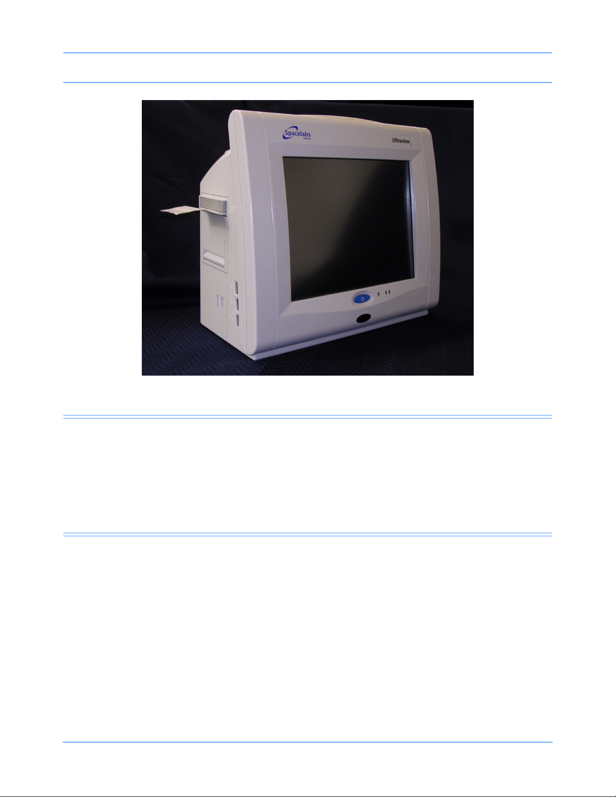
The 91369 monitor is a lightweight, portable monitor designed for use as a compact bedside monitor or as a
battery-operated transport monitor. The monitor features a five-wire, resistive touchscreen and can be
operated on either AC mains or battery power.
The single-high module slot on the right side of the monitor accepts all single-high modules, including the
90496 Ultraview
parameters such as electrocardiography (ECG), pulse oximetry (SpO
®
Command module and 91496 Ultraview SL™ Command module, to permit the monitoring of
), temperature, and invasive pressure.
2
91369 Service Manual 1-1
Page 6
Introduction
Figure 1-1: 91369 monitor
Physical Dimensions
Assembled weight 10.0 pounds (4.6 kg)
Dimensions
8.3 (H) × 11.7 (W) × 6.2 (D) inches
(21.1 × 29.7 × 15.8 cm)
Electrical Specifications
Designed for continuous operation. Requires outlet with ground (Protective Earth) conductor. Designated
Class I by applicable electrical safety standards.
AC Line Requirements
AC input voltage range 100 to 240 VAC
AC input current 1.0 A
AC input frequency range 50 – 60 Hz
91369 Service Manual 1-2
Page 7
Introduction
Environmental Requirements
Operating temperature 0° to 50° C
Humidity (operating) 10% to 95% relative humidity, non-condensing
Regulatory Approvals
®
®
US
US
CSA certified. Meets IEC60601-1, UL60601-1, and CSA C22.2 No. 601.1 for electrical safety. CE marked in
accordance with the Medical Device Directive 93/42/EEC.
0123
Monitor Options
The following options are available:
Table 1: 91369 Monitor Options
Option Definition
D Perioperative
J
N Vital Signs Calculations
O Drug Dose Calculations
Q Data Shuttle
Dual-channel internal recorder (Polish,Czech, Portuguese
language support only)
®
R Patient Data Logger (PDL)
U Dual-channel internal recorder (no Polish language support)
Z Wireless networking
04 Four waveform zones
06 Six waveform zones
91369 Service Manual 1-3
Page 8

Introduction
Display
The video input of the display conforms with the Video Electronics Standards Association (VESA) display
resolution of 1024 × 768 pixels. The monitor does not support an external touchscreen.
Vertical Horizonta l
Rate 64 Hz 51.584 Hz
Front porch 58 μs 0.350 μs
Sync width 116 μs 1.985 μs
Back porch 562 μs 2.101 μs
Blank 737 μs 4.435 μs
Video clock rate 68.5 MHz 51.584 KHz
91369 Service Manual 1-4
Page 9

Setup
Contents
Unpacking the Monitor . . . . . . . . . . . . . . . . . . . . . . . . . . . . . . . . . . . . . . . . . . . . . . . . . . . . . . . . . . . . . . . . . . . .1
Assembling the Monitor . . . . . . . . . . . . . . . . . . . . . . . . . . . . . . . . . . . . . . . . . . . . . . . . . . . . . . . . . . . . . . . . . . .2
Connections . . . . . . . . . . . . . . . . . . . . . . . . . . . . . . . . . . . . . . . . . . . . . . . . . . . . . . . . . . . . . . . . . . . . . . . . . . . .4
Cabling . . . . . . . . . . . . . . . . . . . . . . . . . . . . . . . . . . . . . . . . . . . . . . . . . . . . . . . . . . . . . . . . . . . . . . . . . . . . . . . .7
Network Installation . . . . . . . . . . . . . . . . . . . . . . . . . . . . . . . . . . . . . . . . . . . . . . . . . . . . . . . . . . . . . . . . . . . . .11
Power-ON Test . . . . . . . . . . . . . . . . . . . . . . . . . . . . . . . . . . . . . . . . . . . . . . . . . . . . . . . . . . . . . . . . . . . . . . . . .12
Configuring the Monitor . . . . . . . . . . . . . . . . . . . . . . . . . . . . . . . . . . . . . . . . . . . . . . . . . . . . . . . . . . . . . . . . . .13
Unpacking the Monitor
The 91369 monitor, one or two batteries, external AC power supply, and any optional accessories are all
packaged and shipped in a single box. Keep at least one shipping box and its packing materials for reshipping, if the monitor should ever require factory service.
Caution:
Observe precautions for handling electrostatic-sensitive devices!
Note:
• Never touch electrostatic-sensitive electronic components without following proper anti-static
procedures, including the use of an ESD wrist band and mat. An electrostatic discharge from your
fingers can permanently damage electronic components and cause latent failures.
• All static-sensitive electronic components are packaged in static-shielding bags. Retain the bag for
repackaging the component should you need to store it or return it to Spacelabs Medical for any
reason.
The monitor is typically shipped as follows:
Top Assembly — Contains the main enclosure with installed CPU, power supply, and I/O PCBAs.
Accessories — Contains the external DC power supply, U.S. power cord, international power cords (if
applicable), and any cable assemblies ordered.
Before installing the monitor:
Note:
When removing items from the shipping containers, ensure that you remove ALL components from each
container.
1 Unpack the received equipment.
2 Unpack the mounting hardware.
3 Conduct an equipment audit.
91369 Service Manual 2-1
Page 10
Setup
Upon receiving the equipment, complete a detailed inventory to verify that the equipment you received
matches your order. This inventory must include serial numbers, model numbers, and all options and cables
received. Carefully inspect these items for shipping damage. If any damage is evident, immediately notify the
freight company and Spacelabs Medical.
Assembling the Monitor
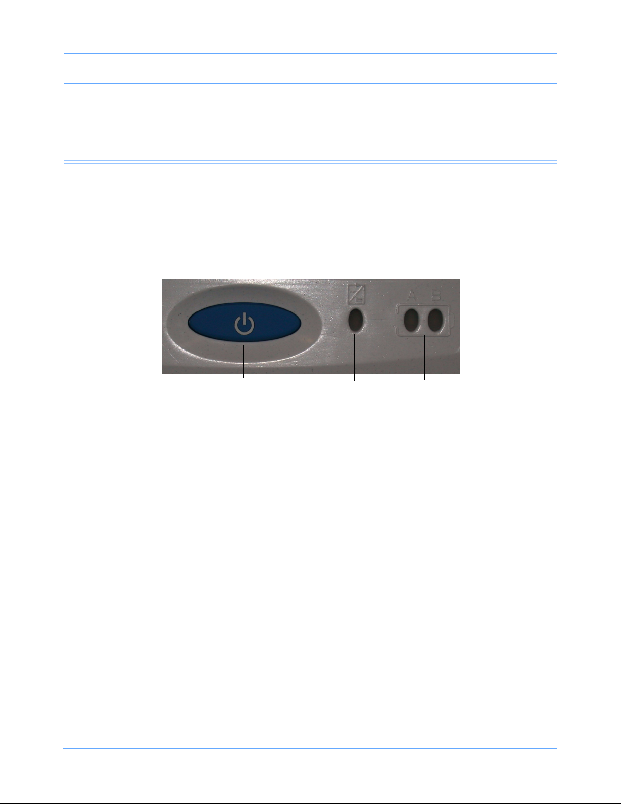
Power and Battery Status
The three LEDs on the monitor indicate whether the monitor is connected to the AC mains power and the
status of any installed batteries. Battery status conditions are indicated as described in the following sections.
INSERT GRAPHIC HERE
Power ON/OFF
switch
Figure 2-1: Battery status information
Power LED
Battery status
LEDs
Power LED
The power LED is located immediately to the right of the power ON/OFF switch. This LED is lit whenever the
monitor is connected to AC mains power via its power supply, and is not lit if the monitor is not connected to
the AC mains power.
Battery Status LEDs
These LEDs are only active while the unit is connected to AC mains power.
Unlit LED
A battery LED that is neither solid ON nor flashing indicates a battery is not present.
Solid Green LED
A solid green battery LED indicates that the battery is fully charged. Only a charging cycle or a faulty battery
will cause the green LED to flash, and these conditions only occur when a battery is installed in the monitor.
91369 Service Manual 2-2
Page 11
Setup
Flashing Green LED — Battery Charging
A flashing green battery LED indicates an installed battery is being charged and the monitor is not completely
ready to be used in transport mode. This LED flashes in a constant pattern with no delays with the monitor
powered ON or OFF. The flashing is different than the battery fault detection flash.
Note:
The green LED stops flashing and stays ON when the charging cycle is complete.
Intermittent Flashing Green LED — Battery Fault Detected
An intermittent flashing green LED indicates that this battery will not hold a charge, or is taking too long to
charge. The intermittent signal is a repeating pattern of a solid green LED for one second and a flashing LED
for one second. An error message is also added to the error log for review by your system administrator.
To determine whether a battery is faulty, power the monitor ON using the front-panel switch and observe the
message displayed along the bottom of the monitor screen. Replace a faulty battery with the same battery
type.
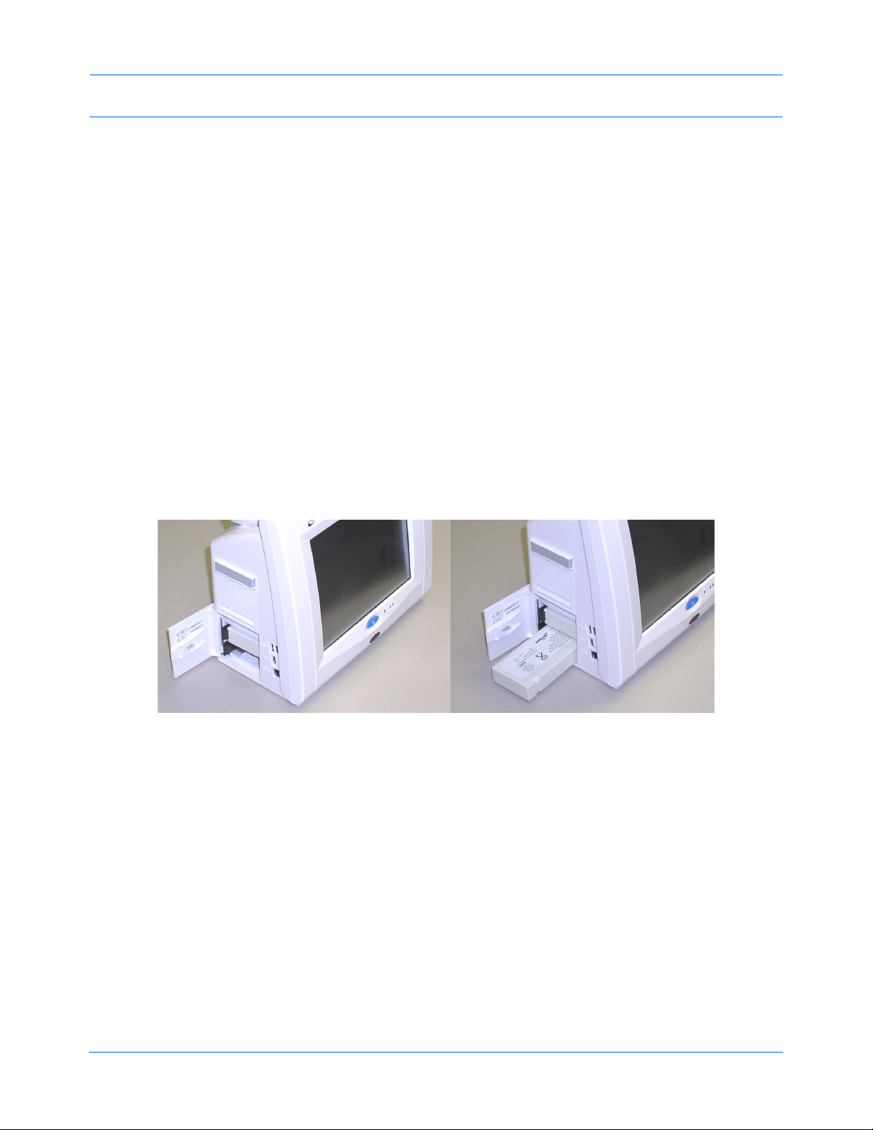
Installing/Replacing Batteries
NiMH batteries are used in the monitor. Refer to Figure 2-2 to install one or two batteries.
Figure 2-2: Monitor battery installation
91369 Service Manual 2-3
Page 12
Setup
While the monitor is operational, a single battery can be exchanged under any of the following conditions
without a loss of patient data:
• The monitor is being powered by the external power supply.
• The monitor is operating on two batteries, and one charged battery remains connected at all times during
the exchange.
Warning:
Batteries exposed to short circuit, high temperature, or fire may leak, vent, or explode.
Caution:
Follow the manufacturer’s recommended handling procedure. Collect and transport batteries in a
manner that prevents short circuit, compacting, mutilation, or any other abuse that would
compromise the physical integrity.
Connections
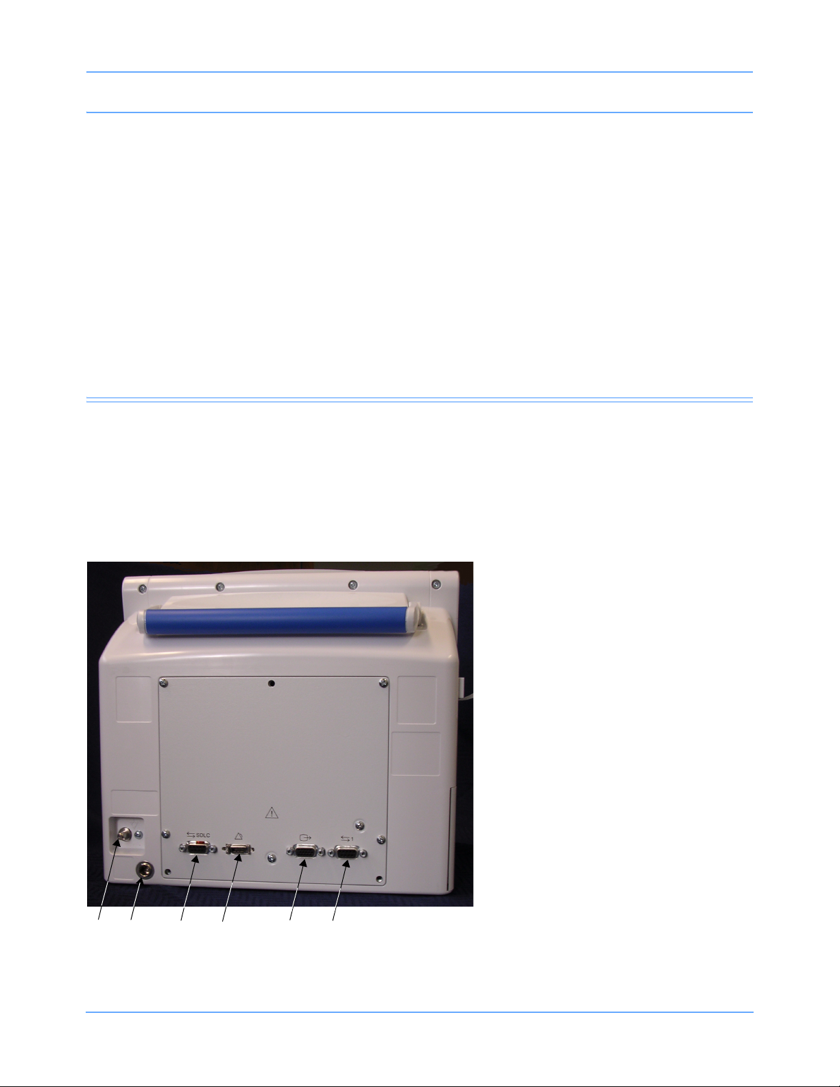
Refer to Figure 2-3 for available connections on the monitor’s rear panel. Refer to Figure 2-4 for available
connections on the monitor’s side panel.
Rear Panel
Equipotential ground post
External power supply input
SDLC port
Alarm relay output
Video output
Serial port
Figure 2-3: Rear panel connections
91369 Service Manual 2-4
Page 13

Setup
Table 1: Rear Panel Cables
Rear Panel
Connection
Cable, Serial I/O (RS-232) As required
Cable, Video, DB15HD Male to DB15HD Male,
1.8 m (6 feet)
Cable, SDLC As required
Cable, Monitor to Module Housing, 0.61 m (2 feet) 012-0532-02
Cable, Monitor to Module Housing, 1.22 m (4 feet) 012-0532-04
Cable, Monitor to Module Housing, 2.44 m (8 feet) 012-0532-08
Cable, Monitor to Module Housing, 3.05 m (10 feet) 012-0532-10
Description Part Number
012-0593-00
Caution:
For continued electromagnetic interference (EMI) radiation compliance, use only cables that have
been tested and approved by Spacelabs Medical. Refer to
numbers.
Table 2 on page 6-3 for all cable part
91369 Service Manual 2-5
Page 14
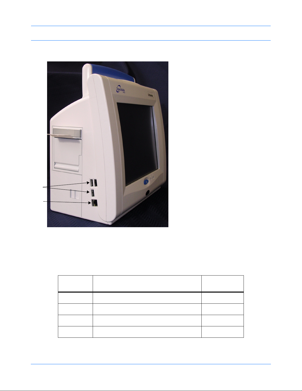
Side Panel
Setup
USB ports
10/100BaseT network
connection
Figure 2-4: Side panel connections
Note:
The USB ports are to be used for Spacelabs-approved devices only (Symbol/Metrologic barcode scanner
and Microsoft USB keyboard/mouse devices).
Table 2: Side Panel Cables
Side Panel
Connection
Cable, Ethernet, 10/100BaseT, 0.94 m (3 feet) 175-0951-00
Cable, Ethernet, 10/100BaseT, 1.8 m (6 feet) 175-0951-01
Cable, Ethernet, 10/100BaseT, 3.7 m (12 feet) 175-0951-02
Description Part Number
91369 Service Manual 2-6
Cable, Ethernet, 10/100BaseT, 6.1 m (20 feet) 175-0951-03
Page 15

Setup
Cabling
Maximum Cable Lengths
The following cables are limited to the indicated maximum length:
• SDLC Cable — 12.2 m (40 feet) maximum (total length from the monitor to the last device on the bus). For
longer SDLC cable runs, contact a Spacelabs Medical Field Service Engineer.
• Video Cable — 30.5 m (100 feet) maximum (total length from the monitor to the last display).
• Ethernet cable (10/100BaseT) — 100 m (328 feet) maximum.
SDLC External Devices
External devices (for example, Flexport® system interfaces) can be connected to the SDLC bus. (In this
context, the term “external” means connected to the SDLC bus by cable via an external connector. This is in
contrast to modules, which are connected by inserting them into a module housing.)
If no supplementary module housings are present (in addition to the module slot integral to the monitor itself),
then external devices are connected directly to the SDLC connector of the monitor.
If one or more supplementary module housings are present, Flexport devices are connected to connector J2
on one of the 90499 or 90491 supplementary module housings, or J3 on model 90485. Refer to the Module
Housings and Power Supplies Service Manual (P/N 070-0680-xx).
If multiple module housings are present, external devices must be connected to the last module housing in the
daisy-chain; that is, the housing electrically farthest from the monitor on the SDLC bus. Even though multiple
connectors may be available, only the SDLC connector on the most distal module housing can be used for
connecting external devices. Do not use more than a single Flexport connector, regardless of how many
module housings are present.
If multiple Flexport interfaces are to be installed, they must be daisy-chained using the T-cable supplied with
those devices. Up to three Flexport interfaces may be connected in this way.
Warning:
Unreliable system operation will occur if the SDLC bus is not correctly terminated or the maximum
cable length is exceeded. Flexport interfaces must be attached to the most distal module housing
on the SDLC bus.
SDLC Cable Interconnection
To ensure electromagnetic interference (EMI) compliance, the appropriate Spacelabs Medical
9-pin connector must be used. Refer to the Module Housings and Power Supplies Service Manual
(P/N 070-0680-xx).
91369 Service Manual 2-7
Page 16
Setup
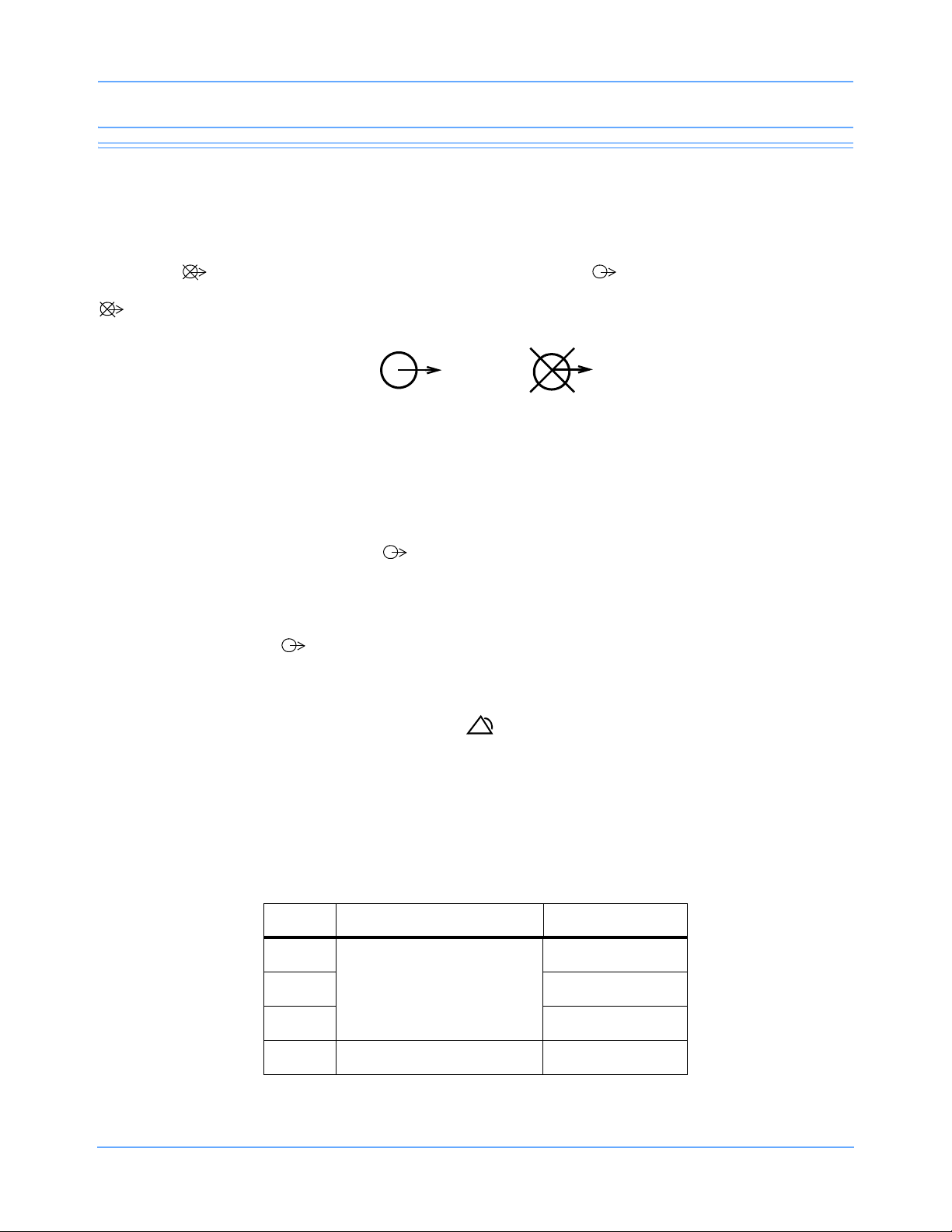
SDLC Bus Termination
The SDLC bus must be properly terminated for correct operation. If no external devices (for example, Flexports
or multigas analyzers) are connected, proper termination of the SDLC bus is accomplished automatically. If
external devices are connected, the switch on the module housing farthest from the monitor must be set to the
terminated ( ) position. All others must be set to the non-terminated ( ) position. The SDLC clock and
data signals are switched by the terminator switches and are not present “downstream” of any switch set to the
position.
Non-terminated Terminated
Figure 2-5: Terminator switch settings
Because bus termination is handled by setting the switches appropriately, an external terminator is only
required when external devices are connected.
If external devices are connected, an external cable terminator is required to terminate the SDLC bus. This
must be installed at the end of the SDLC bus (following the last external device). In this case, all module
housings must have their switches in the position.
Note:
Flexports require a powered Flexport cable (P/N 012-0555-00) when used with the 90491/90499 module
housing or 91369 monitor. SDLC data is only passed along to the external device(s) when the terminator
switch (SW2) is in the
position.
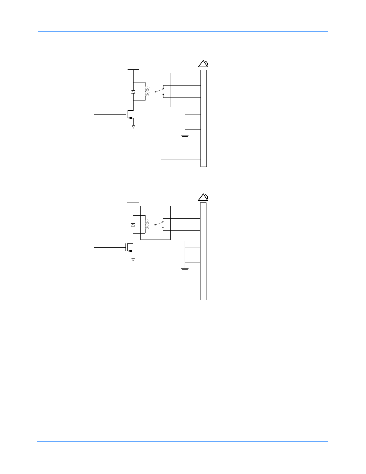
Alarm Relay
Alarm output signals are available at the Nurse Alert ( ) connector instantaneously when an alarm occurs.
Table 3 describes the connector pinouts for remote alarms. Figure 2-6, Figure 2-7, and Figure 2-8 illustrate the
circuits for each alarm function.
External Alarm Pinout
Alarm connector pinouts are as follows:
Table 3: Connector Pinouts
Pin
1
2 Normally Closed
3 Normally Open
Alarm Circuit Meaning
Common
Alarm 0 (high priority)
4GND
91369 Service Manual 2-8
Page 17
Setup
Table 3: Connector Pinouts (continued)
Pin
5
6 Normally Open
Alarm Circuit Meaning
Normally Closed
Alarm 1 (medium priority)
7 Common
8GND
9 +12 V, 140 mA
10 GND
11 GND
12
13 Common
Alarm 2 (low priority)
Normally Open
14 Normally Closed
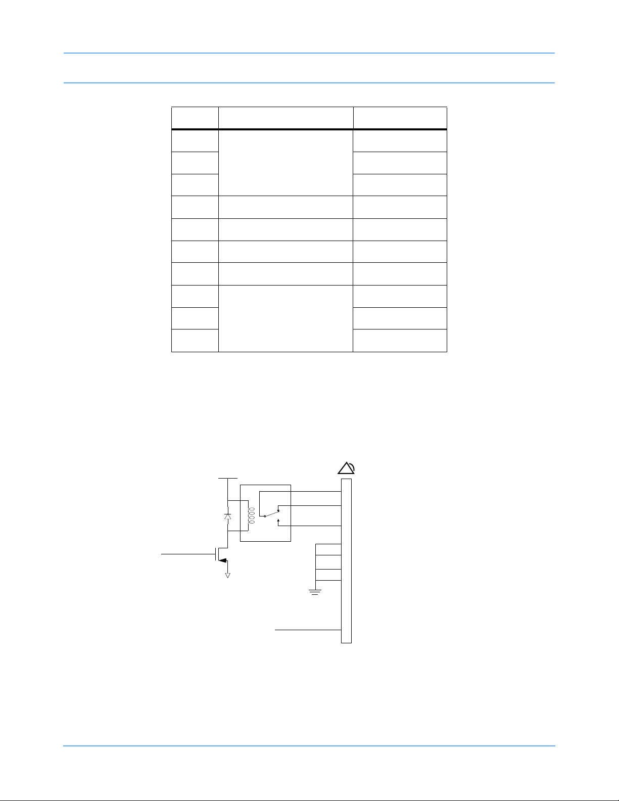
Warning:
For operational safety and reliability, the following relay contact ratings MUST NOT BE
EXCEEDED:
• Current = 250 ma
• Voltage = 28 V AC/DC
ALMON
+5 V
common
NC
NO
relay
+12 V
Relay maximum ratings:
1
2
3
4
8
10
11
9
28 V AC/DC
0.25 A
GND
GND
GND
GND
140 mA
Figure 2-6: Alarm 0 (high priority) relay schematic
91369 Service Manual 2-9
Page 18
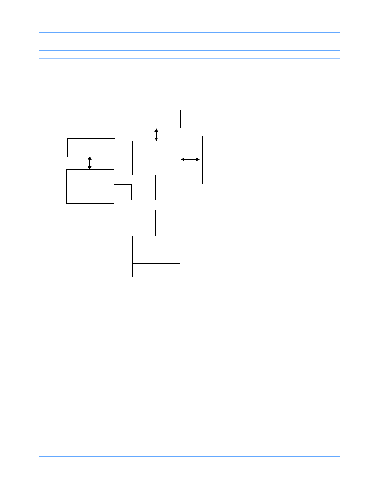
ALMON
+5 V
relay
Setup
common
NC
NO
Relay maximum ratings:
7
5
6
4
8
10
11
28 V AC/DC
0.25 A
GND
GND
GND
GND
ALMON
+12 V
9
140 mA
Figure 2-7: Alarm 1 (medium priority) relay schematic
+5 V
common
NC
NO
relay
+12 V
Relay maximum ratings:
13
14
12
4
8
10
11
9
28 V AC/DC
0.25 A
GND
GND
GND
GND
140 mA
Figure 2-8: Alarm 2 (low priority) relay schematic
91369 Service Manual 2-10
Page 19
Setup
Network Installation
A typical network consists of bedside and central monitors and an optional clinical information system
(Figure 2-9).
94263
Flat-panel display
94260-19
Flat-panel display
91387-38
Central #n
91387-27
Bedside #n
Ethernet Network
91369
Bedside #n
Module
M
o
d
u
l
e
s
Clinical
Information
System
Figure 2-9: Typical network configuration
Warning:
Ensure that the Ethernet wall plate and the shield of the Ethernet connecting cable are bonded to
the hospital grounding system.
Ethernet Network Connection
Caution:
• Only qualified personnel should attempt to connect a monitor to an Ethernet LAN the first time.
• Do not connect the monitor to an Ethernet local area network (LAN) prior to configuring the
following settings. The monitor must be properly configured for LAN access before you operate
the monitor. If you fail to correctly configure the monitor, you may interrupt other units also
using the LAN.
Note:
Detailed installation instructions for the physical Ethernet LAN are beyond the scope of this document.
91369 Service Manual 2-11
Page 20

Setup
To connect a monitor onto an existing Spacelabs Medical Ethernet LAN, complete the following steps:
1 Install the monitor on a suitable table or shelf, ensuring that the air flow to the side air intake vents is
unobstructed, or use a Spacelabs Medical mounting option.
2 Ensure that the monitor is not connected to the LAN.
3 Plug the power cord attached to the monitor’s DC power supply into a standard hospital-grade AC power
supply.
4 Power ON the monitor.
5 Enter a unique MONITOR ID, BED NAME, and SUBNET for the monitor. Refer to Network Setup on page 2-
13 for more information.
6 Attach the 10/100BaseT LAN transceiver cable into the RJ45 connector on the left side of the monitor
(
in Figure 2-4 on page 2-6).
7 Connect the other end of the Ethernet cable from the monitor to the nearest port.
8 Configure the monitor’s other network settings as necessary to ensure proper communication on the
network. Refer to
Network Setup on page 2-13.
Ethernet Network Disconnection
To remove a monitor from the LAN, disconnect the network cable from the 10/100BaseT network connection
(
in Figure 2-4 on page 2-6).
Power-ON Test
Each time the monitor is powered ON:
• Diagnostic information displays for approximately 10 seconds.
• The embedded alarm light cycles red and yellow. Some models may cycle red, yellow, and cyan.
• Monitor keys display on the right side of the screen.
The monitor is now ready for normal operation.
External Devices
If an external SDLC device, such as a Flexport interface, is to be installed, the 9-pin SDLC connector on the
rear of the monitor or the module housing must be used. If multiple SDLC ports on module housings are
available, only the SDLC port on the module housing farthest from the monitor can be used for external
devices. Set the termination switch to non-terminated ( ) for all module housings and then terminate the
external device.
91369 Service Manual 2-12
Page 21

Setup
Module Tests
To verify that the monitor functions correctly with parameter modules:
1 Insert an ECG module without the patient cables connected. Verify that the ECG parameter key is
displayed.
2 Connect a patient simulator to the ECG input with a 5-lead patient cable, and set the simulator to a known
rate.
• Verify that the heart rate and lead being monitored are displayed to the right of the ECG parameter
key.
• Verify that the ECG waveform is displayed.
3 Disconnect the patient cable. After 10 seconds, verify that the LEADS OFF message appears, the
parameter key flashes, and an alarm tone sounds.
4 Reconnect the patient cable and verify that the LEADS OFF message clears and the alarm stops.
5 Connect a patient simulator to the invasive pressure inputs.
6 Zero the pressures and verify that the numerics and waveforms are accurate.
7 Verify that the key tone sounds each time a key is selected.
Configuring the Monitor
The Biomed Level menu displays when the biomed password (default is biomed) is entered into the
Privileged Access window. Refer to Directory of Keys on page 7-1 for the Biomed Level menu structure.
Network Setup
Note:
The NETWORK SETUP key only displays on monitors that are configured for network operation.
Touch NETWORK SETUP to display the Monitor Setup - Network Configuration window. This window
contains an on-screen keyboard and three tabs: TCP/IP, Monitor, and Printers. Proper network operation
requires that each device on the network have a unique network address, monitor ID, and monitor name. If the
wireless option has been installed on the monitor, three more tabs will be present: WLAN, Security, and
Advanced.
Editing Tab Fields
The fields within a tab on the Monitor Setup - Network Configuration window can be edited by selecting the
field and entering new information using the on-screen or optional external keyboard.
When editing, adding, or deleting, press ENTER or TAB to cycle to the next input cell. Any changed or added
items are stored in the monitor’s non-volatile memory when SAVE is selected. The description of each tab
indicates when that change takes effect (for example, immediately or after a monitor reset occurs).
To edit text within a tab:
1 Select an item from the list.
-OR-
91369 Service Manual 2-13
Page 22
Setup
2 Select an input cell’s text and type any combination of letters, characters, or spaces.
To add an item to a list:
• Select the input cell and type the new information.
To delete an item from a list:
1 Select the item.
2 Touch Del.
3 Enter at least one space (an error message is displayed if no spaces are entered).
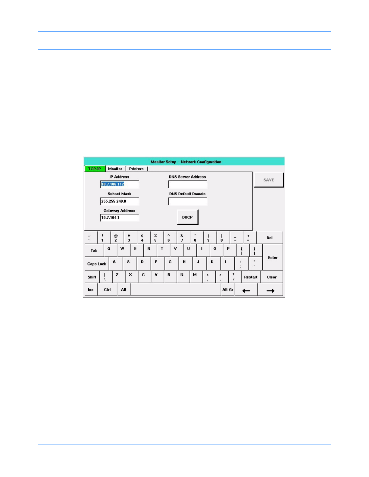
TCP/IP Tab
Figure 2-10: TCP/IP tab
The TCP/IP tab enables you to define the monitor’s attributes for networking.
IP Address — Enables you to specify the monitor’s IP address. The default is 164.90.254.10. Either a static IP
address must be specified, or DHCP networking must be enabled.
Subnet Mask — Enables you to identify which parts of the IP address are to be used for TCP/IP subnet
determination. The TCP/IP network’s subnet mask is not related to the Spacelabs Medical network’s subnet
name. The standard and factory-default subnet mask is 255.255.255.0. Either a subnet mask must be
specified, or DHCP networking must be enabled.
Gateway Address — Enables you to specify the IP address of the TCP/IP gateway (bridge or router) though
which communication to other devices should flow. The default is blank.
DHCP — (Dynamic Host Configuration Protocol) Used to configure and enable DHCP network configuration.
When DHCP is enabled, IP Address, Subnet Mask, and Gateway Address are automatically filled in. To use
this service, a DHCP server must be available on the network to respond to DHCP requests.
91369 Service Manual 2-14
Page 23

Setup
Note:
• A DHCP lease is a TCP/IP configuration given out from the DHCP server that is valid for a period
defined by the DHCP server or forever (no expiration).
• Monitors configured for DHCP operation request a lease from the DHCP server when they boot up or
when their existing lease expires during operation. If the DHCP server is not present, the monitor
checks the expiration time of the last DHCP lease obtained. If the lease is still valid, the monitor
continues to use those values and operates normally. If the lease has expired, the monitor disables
TCP/IP networking and displays a NETWORK SIGNAL LOST message to indicate that it is unable to
communicate over the network. The monitor continues to request a DHCP lease until it receives one.
• If the monitor’s configured DECNET node ID is a duplicate on the network, the DHCP server can be
confused. This may result in a duplicate or invalid DHCP lease and may prevent full network
communication.
• The subnet mask must correctly correspond to the network size and type during operation. Monitors
may not be able to fully communicate with each other if the DHCP server fails to set the network mask
properly.
The DNS server address is in standard TCP/IP address form, while the DNS default domain is a string of
ASCII characters. A DHCP server may also provide this information.
Editing this tab is performed as described in Editing Tab Fields on page 2-13. Tabbing order is IP Address >>
Subnet Mask >> Gateway Address >> DHCP >> DNS Server Address >> DNS Default Domain >> IP
Address. Changes made to this tab’s settings take effect after a successful save and monitor reset.
Secondary Display — The Secondary Display field is only available if option -D, Perioperative, has been
activated.
Select ENABLE on the TCP/IP tab to activate the primary monitor’s secondary display. When you enable the
secondary display, the IP Address and Secondary Hostname fields become available and must contain a
valid entry for the secondary monitor to operate. The IP Address and Secondary Hostname fields are
exclusive to each other.
Enter a valid IP Address when your network is using static IP addresses.
-OR-
Enter a valid Secondary DNS hostname when your network is using DHCP for network configuration.
Changes made to the Secondary Display settings take effect after the changes have been saved.
91369 Service Manual 2-15
Page 24
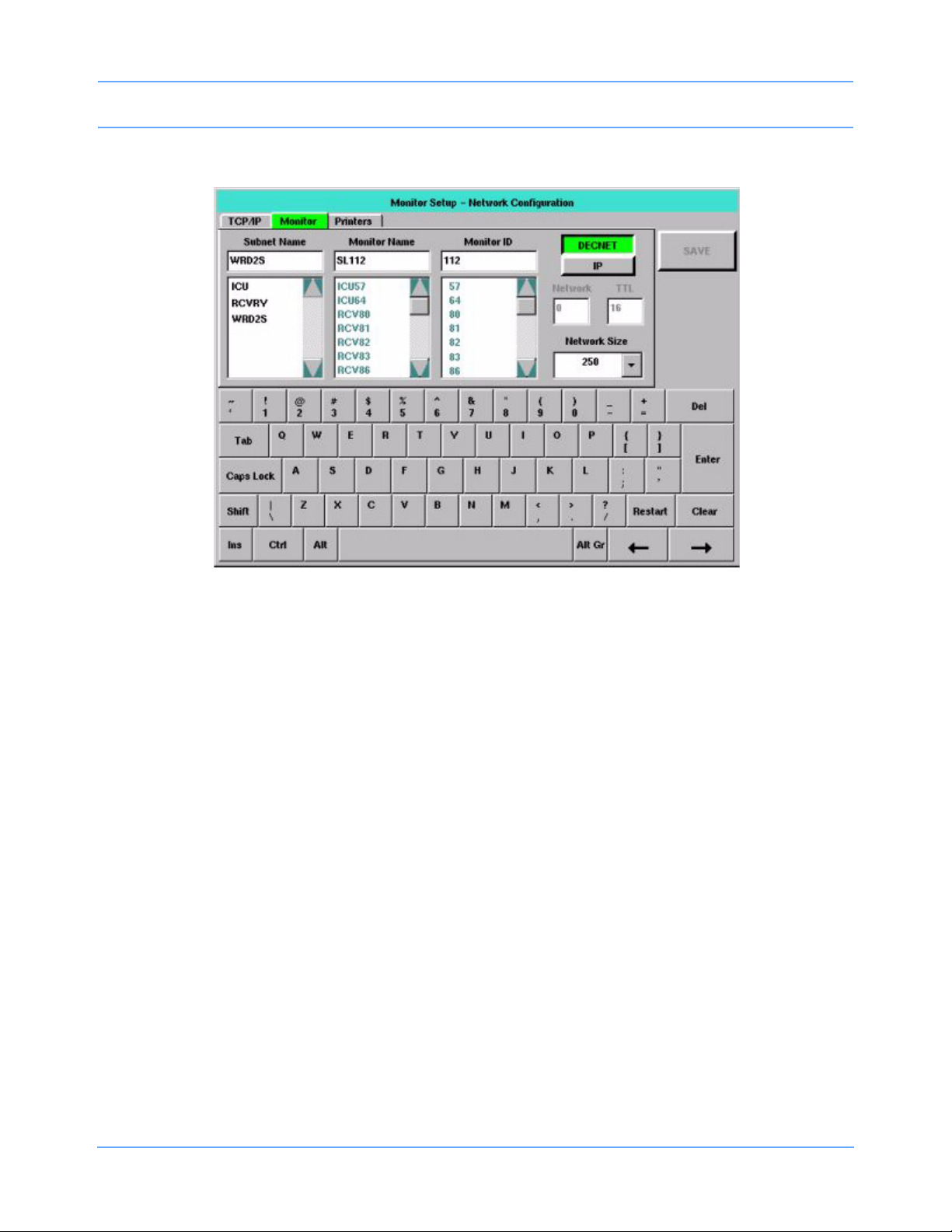
Monitor Tab
Setup
Figure 2-11: Monitor tab
The Monitor tab enables you to determine what monitor names, monitor (node) IDs, and subnet names are
currently in use. The tab also enables you to enter settings for the monitoring network.
In Figure 2-11, the monitor’s current settings are displayed in each input cell. The scroll list below each input
cell displays the remaining items that have been detected on the network. Items in the Subnet Name and
Monitor Name lists are displayed in alphanumeric order. Items in the Monitor ID list are displayed in numeric
order.
Brackets (< >) surround strings that consist solely of spaces. The separation within the brackets indicates the
number of spaces within that string.
Editing is performed as described in Editing Tab Fields on page 2-13. The tabbing order is Subnet Name >>
Monitor Name >> Monitor ID >> DECNET/IP >> Network >> TTL >> Subnet Name. Network and TTL are
skipped if unavailable. Changes made to this tab’s settings take effect after a successful save and monitor
reset.
Subnet Name
The subnet name contains up to five characters (default is five blanks). Items in this scroll list are selectable.
Monitor Name and Monitor ID
The Monitor Name is the name given to each bedside and central monitor (does not apply to telemetry bed
names) to help the users identify monitors on the network. The Monitor Name contains five characters (default
is SL001).
The Monitor ID is the numeric ID assigned to a monitor. Each device on the network must have a unique
Monitor ID. This can be any number from 1 to 1023, depending on the Network Size selected.
91369 Service Manual 2-16
Page 25

Setup
To prevent duplication of currently used monitor names and IDs, items in these lists are not selectable. The
error checking procedure performed when SAVE is selected also specifically checks for duplications.
Note:
• Items in the Monitor Name and Monitor ID lists only display when the monitor is connected to the
network.
• When entering a monitor name or ID, do not use a space between characters.
DECNET/IP
You can configure the monitor to operate using either Spacelabs DECNET or TCP/IP network protocols. If you
are communicating with 903xx Spacelabs Medical monitors, you must select DECNET.
Network
The IP multicast group number of the monitor provides a filter to logically isolate one monitor from another on
TCP/IP installations. Up to 32 network numbers are available (0 to 31) with 0 as the default.
Note:
• Monitors must use the same network number to communicate.
• This is unavailable if DECNET is selected.
TTL (Time to Live)
The allowed number of hops the IP packet can take across network devices. TTL values are 1 to 64, with 16 as
the default.
Note:
TTL is unavailable if DECNET is selected.
Network Size
The network size allows configuration as:
64 — Monitor IDs from 1 to 64 are supported. No more than 64 total monitor devices can be on the
network. Provides complete network compatibility with legacy Spacelabs Medical monitors.
250 — Monitor IDs from 1 to 250 are supported.
Note:
903xx monitors must have the Expanded Network option installed or they will not communicate correctly
with devices with Monitor IDs above 64.
640 — Monitor IDs from 1 to 127 and from 512 to 1023 are supported with the following restrictions.
• All model 903xx Spacelabs Medical monitors must use monitor IDs 1 to 127, inclusive.
• All model 91xxx monitors must be configured with monitor IDs from 512 to 1023, inclusive.
1000 — Monitor IDs from 1 to 1023 are supported (compatible only with Spacelabs Medical 91xxx series
monitors).
91369 Service Manual 2-17
Page 26
Setup
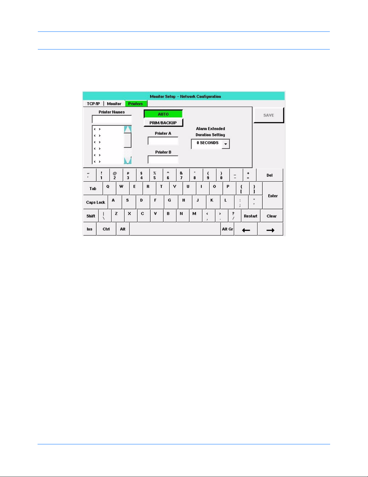
Printers Tab
The Printers tab enables you to display controls for defining and storing printer names, choosing rules for
printer selection, and selecting one or two network printers.
Figure 2-12: Printers tab
Editing is performed as described in Editing Tab Fields on page 2-13. The tabbing order is AUTO / PRIM/
BACKUP >> Printer A (or Primary) >> Printer B (or Backup) >> Printer Names (refer to Figure 2-13 on
page 2-19). Changes made to this tab’s settings take effect after a successful save and monitor reset.
Printer Names
The Printer Names list displays up to eight, selectable printer names previously stored in the monitor, in the
order in which they were stored. To display a new or changed name in the list, select that printer name from the
list. Printer names contain up to five characters (default is five blanks).
Note:
• Printer names are explicitly entered and may be duplicated. To clear a printer name from the list, select
that name, touch Clear, touch Enter, and then touch SAVE.
• A local (SDLC) printer can be either a bedside printer or network printer, depending on the printer name
selected in this list. A local printer is configured as a network printer if the local monitor’s name is
selected. Otherwise, a local printer functions as the bedside printer.
91369 Service Manual 2-18
Page 27
Setup
AUTO / PRIM/BACKUP
The AUTO / PRIM/BACKUP key selects which set of printer selection rules the monitor uses for selecting
network printers. It does not affect the monitor’s selection of whether a networked or non-networked printer is
used. Any changes made to the printer selection mode using this key take effect immediately, regardless of
monitor type. The default setting is AUTO, which selects the destination printer using the weight-based printer
selection rules. (Refer to the Ultraview SL Operations Manual, P/N 070-1150-xx, located on CD-ROM
P/N 084-1101-xx for additional information).
When PRIM/BACKUP is selected, the monitor automatically selects the primary printer, unless that printer is
unable to accept the recording. In that instance, the monitor then selects the backup printer. If the backup
printer is also unable to accept the recording, the monitor displays an Unable to record message.
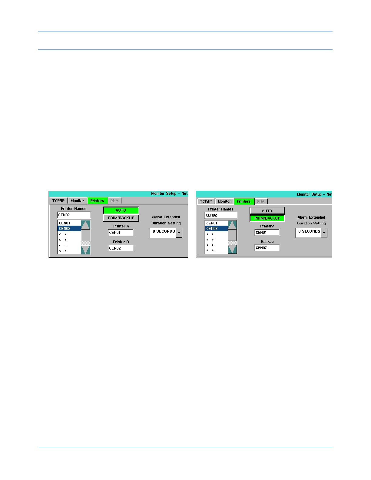
Printer Selection Fields
The default for the printer selection fields is blank (i.e., no printer selected). The labels above these fields vary,
based on the current setting of the AUTO / PRIM/BACKUP key. If AUTO is selected, the labels are Printer A
and Printer B. If PRIM/BACKUP is selected, the labels are Primary and Backup (Figure 2-13).
Figure 2-13: AUTO / PRIM/BACKUP selection differences
To define a printer name:
1 Select a printer name from the Printer Names list.
2 Select one of the two printer selection fields. The new value displays in the selected field.
WLAN Tab
This tab allows the operator to set basic wireless local area network (WLAN) related settings.
The WLAN tab only displays on monitors that are configured for wireless operation (option -Z). Monitors are
configured for wireless operation by selecting the sysgen RADIO option. The RADIO ON/OFF keys and all
other input cells and combo boxes illustrated in Figure 2-14 are not available for selection if the radio is not
present.
Caution:
Do NOT power the radio ON until all network configuration has been completed. Powering the radio
ON with the monitor set to the factory defaults could interfere with the wireless network.
91369 Service Manual 2-19
Page 28
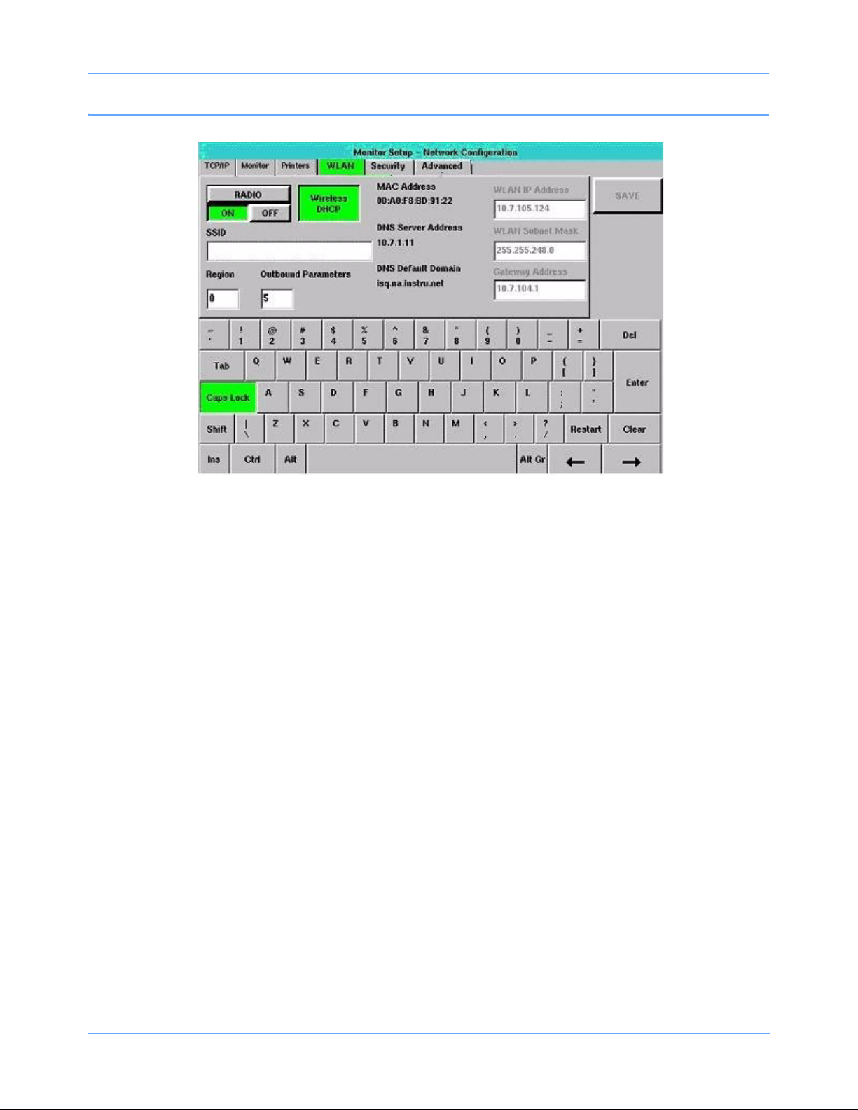
Setup
Figure 2-14: WLAN tab
The tabbing order is RADIO ON/OFF >> SSID >> Region >> Outbound Parameters >> Wireless DHCP >>
WLAN IP Address >> WLAN Subnet Mask >> Gateway Address >> RADIO ON/OFF. WLAN IP Address,
WLAN Subnet Mask, and Gateway Address are not available in the tabbing order if Wireless DHCP is
selected. Changes made to this tab’s settings take effect after a successful save and monitor reset.
RADIO ON/OFF (default = OFF)
The RADIO ON/OFF setting defaults to OFF when a radio is present. If this key is toggled to ON, and SAVE is
selected without a valid region defined [refer to Region (default = blank) on page 2-22], an error box displays
(the radio cannot be switched to ON if the Region setting is invalid). Select OK to remove the error box. The
RADIO ON/OFF key automatically toggles back to OFF.
The radio will function only if this key is set to ON. Keys, input cells, select boxes, and combo boxes are
enabled without regard to the setting of this key. However, WLAN communication only occurs if ON is selected.
Note:
Any change in the wireless tabs (except for the setting of the OUTBOUND PARAMETERS input cell)
requires a monitor reset before the changes take effect.
To activate the radio-only functions, select ON.
Wireless DHCP (default = OFF)
The Wireless DHCP tab is similar in function to the DHCP key on the TCP/IP tab, but for wireless networks.
When Wireless DHCP is selected, the monitor asks the wireless DHCP server for the following information:
• WLAN IP Address
• WLAN Subnet Mask
• Gateway Address
91369 Service Manual 2-20
Page 29

Setup
The affected input cells then display the values provided by the wireless DHCP server, rather than the values
from the monitor’s non-volatile memory. These cells then become unavailable for selection, to prevent these
values from being changed, until Wireless DHCP is de-selected.
If Wireless DHCP is selected, as in Figure 2-14 on page 2-20, DNS Server Address and DNS Default
Domain values display, and the WLAN IP Address, Wireless Subnet Mask, and Gateway Address input
cells are unavailable for selection.
When Wireless DHCP is not selected, the DNS Server Address and DNS Default Domain values disappear,
and the WLAN IP Address, Wireless Subnet Mask, and Gateway Address input cells are available.
Table 4: Wireless DHCP Input Cells
Is this cell
Can the wireless
Cell name
WLAN IP Address Yes Yes No
WLAN Subnet Mask Yes Yes No
Gateway Address Yes Yes Yes
DHCP server provide
this information?
unavailable if the
wireless DHCP
server provides the
information?
Can the cell be left
blank?
Note:
Input cells that display wireless DHCP server-provided data may display values different than what is
stored in the monitor’s non-volatile memory. DHCP server-provided values are not stored in non-volatile
memory.
SSID (default = blank)
The SSID cell is used to define the WLAN Service Set Identifier (SSID) setting, which is the name used by
acceptable access points (AP) for that WLAN. This field is up to 32 characters long, and it may contain any
combination of case-sensitive characters. The default is blank.
Setting SSID and Security Mode
If enabled, WLAN card communication through the wireless network depends on the interaction between the
WLAN card SSID setting (refer to SSID (default = blank)) and its security settings (refer to Security Tab on
page 2-24).
91369 Service Manual 2-21
Page 30
Setup
The WLAN card SSID and security settings must match the settings of the intended access point (AP). If the
settings do not match, then wireless communication cannot occur.
Table 5: WLAN Card and Security States
SSID
No
Match
No
Match
No
Match
SSID
Matches
SSID
Matches
SSID
Matches
SSID
Matches
Security
Mode
WEP
Disabled
WEP
Enabled
WEP
Enabled
WEP
Disabled
WEP
Enabled
WEP
Enabled
WEP
Enabled
WEP
Authentication
Open N/A No No
Open N/A No No
Shared Key N/A No No
Open N/A Yes Yes
Open Yes Yes Yes Yes
Open No Yes No No
Shared Key Yes Yes Yes Yes
Keys
Match?
Monitor
Associated?
Monitor
Authenticated?
Communication
No — SSID must
always match
Yes, but only if
Security Mode on
AP matches (WEP
optional)
Can Wireless
Occur?
SSID
Matches
Region (default = blank)
This input cell displays the monitor’s current setting for the WLAN region. This cell is available for 802.11
radios that are configurable in the field. Region values and their corresponding geographical regions are listed
in Table 6. The frequencies available in a particular country differ according to the regulations of that country.
Consult your national and local regulations.
91369 Service Manual 2-22
WEP
Enabled
Shared Key No No No No
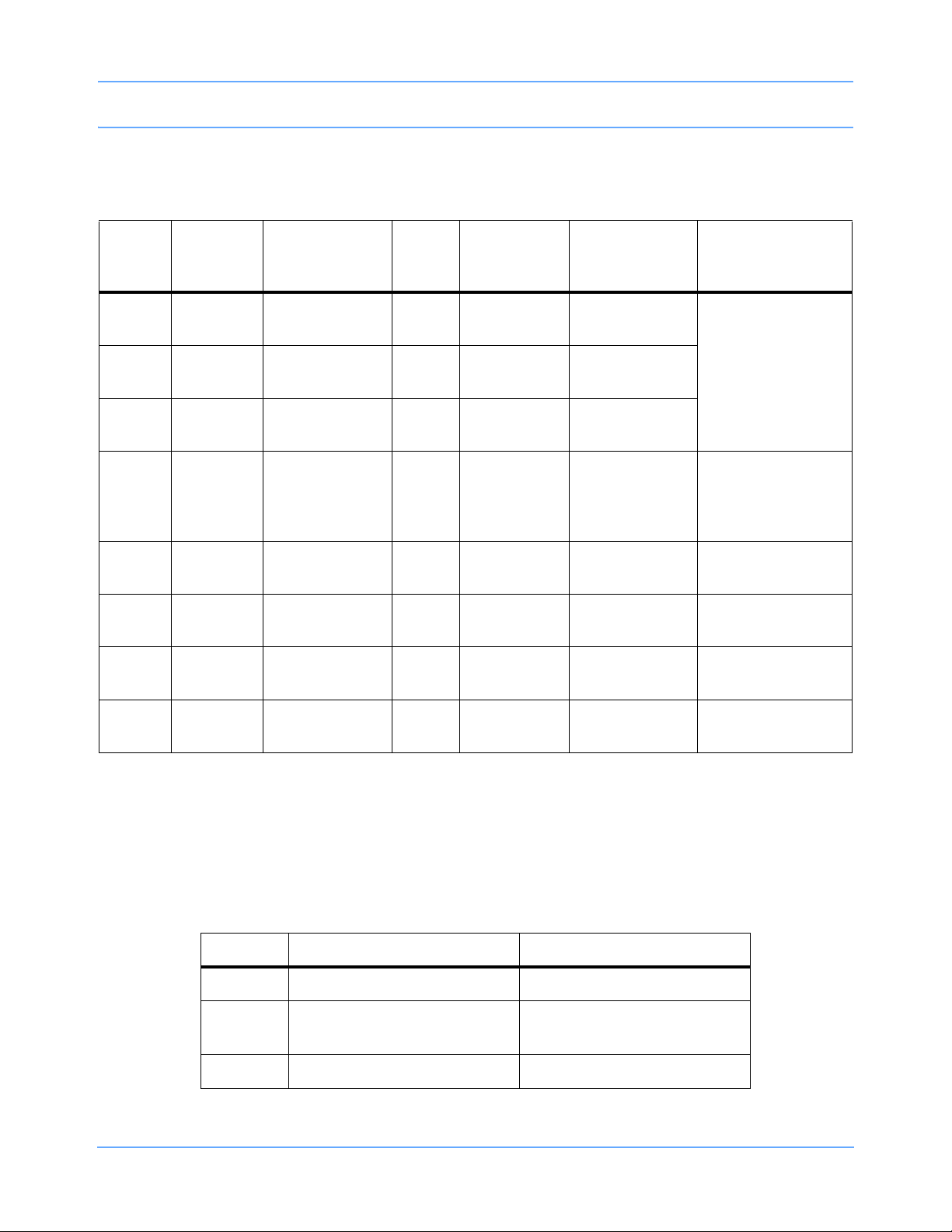
Table 6: Region Codes
Value Center Frequency Range Region
Blank Disabled
1 2412 to 2472 MHz
2 2412 to 2462 MHz North America
Europe (ETSI), except France
and Spain
Page 31

Setup
Table 6: Region Codes
Value Center Frequency Range Region
3 2412 to 2472 MHz Japan (MKK)
4 2457 to 2462 and 2484 MHz Japan
5 2412 to 2472 MHz France
6 2457 to 2462 MHz Spain
Note:
Selecting SAVE when the currently entered value for Region is not valid displays the “Cannot switch Radio
ON with invalid region” error dialog box. Selecting OK toggles RADIO ON/OFF to OFF, disabling the radio.
Outbound Parameters (default = 5)
This input cell displays this monitor’s configuration setting for the number of parameters that are displayed in
bed selection dialog boxes. Valid values range from 0 through 6 (default = 5), with blank equating to 0.
MAC Address
The radio’s assigned MAC address (in hexadecimal) displays below this label.
DNS Server Address and DNS Default Domain
The radio’s DHCP server-assigned DNS server address (in IP format) and DNS default domain name (in text)
display below these labels, but only when Wireless DHCP is selected.
WLAN IP Address (default = 0.0.0.0)
Allows the operator to specify the IP address for the wireless network interface, when Wireless DHCP is not
selected.
WLAN Subnet Mask (default = 0.0.0.0)
Allows the operator to identify which parts of the wireless IP address to use for TCP/IP subnet determination,
when Wireless DHCP is not selected. Wireless subnet mask is not related to the Monitoring network’s subnet
name or subnet mask.
Gateway Address (default = 0.0.0.0)
Allows the operator to specify the IP address of a wireless TCP/IP gateway (bridge or router) through which
wireless communication to other devices should flow, when Wireless DHCP is not selected. The Gateway
address on the WLAN tab is not related to the Gateway address on the TCP/IP tab.
91369 Service Manual 2-23
Page 32

Setup
Security Tab
The Security tab provides access to the WLAN security settings. The Security tab only displays on monitors
that are configured for wireless operation.
Figure 2-15: Security tab
In the left portion of Figure 2-15, Security Mode is set to Disabled in the Security Mode combo box pull-down
menu. In the right portion of Figure 2-15, Security Mode is set to WEP128, after entering hexadecimal keys.
Note:
Any entered WEP keys are erased if Security Mode is set to Disabled and the new setting is saved. If
Disabled is selected but not saved, the WEP keys are not erased.
The tabbing order depends upon the currently selected setting for Security Mode.
When Security Mode is set to Disabled, the tabbing order is Security Mode >> SAVE >> Security Mode.
When Security Mode is set to a WEP setting, the tabbing order is Security Mode >> Authentication Mode
>> Transmit (WEP Key1) >> Transmit (WEP Key2) >> Transmit (WEP Key 3) >> Transmit (WEP Key4) >>
WEP Key1 >> WEP Key2 >> WEP Key3 >> WEP Key4 >> Security Mode. Changes made to this tab’s
settings take effect after a successful save and monitor reset.
Note:
• In the tabbing order, the position of input focus on the combo boxes and the EDIT keys is not visually
apparent. Input focus on a key can be determined by selecting the ENTER key on the keyboard (the
key highlights). Selecting one of the WEP keys also clears the input cell to its right, enables that input
cell and gives it input focus). Input focus on a combo box can be determined by using the up or down
arrow keys on a USB keyboard to move through the list items.
• The tabbing order skips the SAVE key when that key is unavailable.
Security Mode
A combo box displays the monitor’s current Security Mode selection and provides the operator with a way to
change that selection. This setting determines whether WLAN operation is disabled (not encrypted) or is
enabled with encryption using either the WEP40 or the WEP128 protocols.
Whenever Disabled is selected, the only other items displayed within the tab are the Authentication Mode key
(disabled with OPEN selected) and the SAVE key. If Disabled is selected and saved, the SAVE key becomes
unavailable.
91369 Service Manual 2-24
Page 33

Setup
Selecting WEP40 or WEP128 enables the Authentication Mode setting (the selection does not change) and
displays Transmit Key with four keys below it. WEP Key1 through WEP Key4 display with corresponding
input cells.
When Security Mode is set to WEP40 or WEP128, the WEP keys and the key sizes for the WLAN APs and
wireless monitors must be identical for wireless communication to occur.
Changing Security Mode from Disabled to WEP40 or WEP128 causes a working WLAN to stop working, if
the WEP keys and key sizes do not exactly match throughout the WLAN.
If the WLAN security settings have never been configured, or if you are changing the setting from Disabled to
WEP40 or WEP128, then the four WEP key input cells are blank. If the WLAN security settings were previously
configured, then the four WEP key input cells reflect whether that WEP key was defined (see WEP Keys).
Transmit Key
These four keys indicate which of the available WEP Keys is used for wireless data transmission. By default,
none of these keys are selected. Selecting any of these four keys displays an “x“ mark within that key and
cancels the selection of any other previously selected transmit key.
WEP Keys
A WEP key is either 10 or 26 hexadecimal characters in length, depending upon whether the selected WEP
key size is 40 or 128 bits, respectively.
A WEP key can be cleared or entered. After it has been entered, the hexadecimal entry cannot be edited (it
must be re-entered). The WEP key input cells, labeled WEP Key1, WEP Key2, WEP Key3, and WEP Key4,
indicate whether that WEP key is defined for use when WEP security is selected. These input cells are blank if
a WEP key has not been entered. If you accidentally delete a WEP key that was needed, and you have not
saved this change, you can restore the WEP key setting by exiting NETWORK SETUP and then returning to
NETWORK SETUP.
A WEP key input cell reflects the characters being typed during input of a WEP key. After the WEP key is
stored, the input cell for the entered WEP keys displays one asterisk for each character in the stored WEP key
(10 asterisks if the selected key size is 40; 26 asterisks if it is 128). This indicates that the key was defined, but
the value is hidden for security purposes.
If the WEP key is non-null when a key size change occurs, then the contents of the WEP key input cells clear.
Selecting a WEP key
Selecting any of these four keys (WEP Key1, WEP Key2, WEP Key3, or WEP Key4) highlights that key,
disables any available WEP key input cell, enables the WEP key input cell to the right of the selected key,
clears the contents of the enabled input cell, and positions the cursor at the far left of that input cell.
Authentication Mode
The 802.11b WLAN cards (radios) that Ultraview SL monitors use for wireless networking support two methods
of authentication between wireless clients and the AP: Open and Shared Key. Wireless networking is only
available if the authentication modes of the AP and the WLAN card match.
Setting Security Mode to Disabled disables this key, with OPEN selected.
91369 Service Manual 2-25
Page 34

Setup
OPEN Authentication
Open authentication simply requires that the SSID for the monitor’s WLAN card match that of the AP. The AP
must also be set for open authentication. Refer to Table 5 on page 2-22.
Shared Key authentication
In Shared Key authentication, the AP sends the monitor’s WLAN card a challenge text string that the WLAN
card encrypts (using its WEP key) before returning it to the AP. If the monitor’s WLAN card WEP key does not
match the AP’s WEP key, the AP rejects the encrypted text and will not allow the WLAN card to associate with
it. Refer to Table 5 on page 2-22.
Advanced Tab
The Advanced tab provides access to the advanced WLAN settings. The Advanced tab only displays on
monitors that are configured for wireless operation. The left window of Figure 2-16 displays the Advanced tab;
the right window illustrates the window with the Data Rate combo box displayed. Changes made to this tab’s
settings take effect after a successful save and monitor reset.
Figure 2-16: Advanced tab
Editing this tab is performed as described in Editing Tab Fields on page 2-13. The tabbing order is Data Rate
>> RTS Threshold >> Fragmentation Threshold >> Data Rate.
Note:
In the tabbing order, position of input focus on the combo box is not visually apparent. Input focus on a
combo box can be determined by using the up or down arrow keys on a USB keyboard to move through
the list items.
Data Rate (default = blank)
A combo box displays the current WLAN Data Rate selection. The operator may change that selection using
this combo box.
When selecting a Data Rate, select the maximum data rate that the WLAN interface should use when sending
unicast and multicast data packets. The WLAN interface uses a lower rate if reliable network communication
cannot occur at the selected higher data rate.
91369 Service Manual 2-26
Page 35

Setup
RTS Threshold (default = 0)
Valid values are in the range of 0 to 2339, inclusive.
Fragmentation Threshold (default = 0)
Valid values are in the range of 256 to 2338, inclusive. The default setting is 0.
Network Configuration Messages
The following messages may occur if a networking entry is misconfigured. The default setting is 0.
Cannot switch Radio ON with invalid region
Monitors display this warning if the value displayed in the Region input cell on the WLAN tab [refer to Region
(default = blank) on page 2-22] is invalid and SAVE is selected.
TTL XX is out of range (either < 1 or > 64)
Where XX is the value entered in the TTL cell on the Monitors tab. (Monitors display this warning when the
TTL input cell loses focus if the entered value is not within the valid range.) If the value entered is nonnumeric,
then the displayed value changes back to the most recently saved numeric value.
WEP KeyY invalid. This key should be 26 HEXADECIMAL characters
(when WEP128 is selected);
-OR-
WEP KeyY invalid. This key should be 10 HEXADECIMAL characters
(when WEP40 is selected).
Monitors display one of these warnings if the value entered in that WEP key’s input cell on the Security tab
contains a nonhexadecimal character and SAVE is selected.
Wireless configuration out or range error messages
Monitors display one of the following warning messages if that input cell’s value for the WLAN is out of range,
and SAVE is selected. XXXXX represents the entered value.
Wireless Fragmentation Threshold XXXXX is out of range (either <256 or > 2338) (Advanced tab).
Wireless RTS threshold XXXXX is out of range (either <0 or >2339) (Advanced tab).
Wireless outbound parameters XXXXX is out of range (either <0 or > 6) (WLAN tab).
Invalid Region Code — XXX (either <0 or > 99) (WLAN tab).
Note:
If the invalid IP address or subnet mask is related to use of the WLAN, monitors that are configured for
radio/WLAN operation append “WLAN” to the start of the error messages describe below.
91369 Service Manual 2-27
Page 36

Setup
Gateway Address xx.x.xxx.xxx is out of range or invalid
Refers to the WLAN tab. Monitors display this on the keyboard window’s error line or in a warning dialog box if
the form of the IP address is invalid (not in the form xxx.xxx.xxx.xxx, where X is a number) and SAVE is
selected.
WLAN IP address xxxxx is out of range or invalid
Refers to the WLAN tab. Same as for Gateway Address xx.x.xxx.xxx is out of range or invalid, where xxxxx is
the entered IP address.
WLAN Subnet Mask xx.x.xxx.xxx is out of range or invalid
Refers to the WLAN tab. Same as for Gateway Address xx.x.xxx.xxx is out of range or invalid.
Serial Ports
Refer to Directory of Keys on page 7-1 for the menu structure.
Patient Data Logger (Option R)
The Patient Data Logger option automatically sends patient vital signs from the monitor to a serial external
device, such as a printer or a terminal. Episodic patient data is also sampled and transmitted. The output is in
the form of ASCII text byte strings and is printed using standard RS-232 serial communications via the
monitor’s serial port (refer to the Ultraview SL Operations Manual, P/N 070-1150-xx, located on CD-ROM
P/N 084-1101-xx for configuration information).
This option continues to send data whether the external device is on-line or off-line. Data transmission can be
stopped by reassigning the data port or disabling the Patient Data Logger option.
Communication between the monitor and the external device is set up by assigning the serial port to Patient
Data Logger and then adjusting the serial port settings. The various serial settings can be adjusted to suit the
device attached to the serial port.
To set up Patient Data Logger:
1 Touch MONITOR SETUP.
2 Touch PRIVILEGED ACCESS.
3 Enter the biomed password (default is biomed).
4 Touch SERIAL PORTS.
5 Touch ASSIGNMENT.
6 Touch DATA LOGGER.
7 Touch PREVIOUS MENU.
91369 Service Manual 2-28
Page 37

Setup
Vitalink
Vitalink is a Draeger-defined asynchronous serial communication protocol for use only with Draeger devices.
To set up
1 Touch MONITOR SETUP.
2 Touch PRIVILEGED ACCESS.
3 Enter the biomed password (default is biomed).
4 Touch SERIAL PORTS.
5 Touch ASSIGNMENT.
6 Touch VITALINK.
7 Touch PREVIOUS MENU.
Vitalink:
Serial Settings
To set serial settings:
1 Touch SETTINGS.
2 Touch the desired setting key(s) to display and set the desired settings.
3 Touch NORMAL SCREEN to effect changes.
Monitor Calibration
The MONITOR CALIBRATION key in the Biomed Level menu allows you to perform a touchscreen calibration
in the event the touchscreen becomes difficult to use or a replacement has been installed. Refer to
Touchscreen Calibration on page 4-4 for instructions on performing this calibration.
Change Biomed Password
The CHANGE BIOMED PASSWORD key in the Biomed Level menu enables you to change the password
used to access the Biomed Level menu.
To change the biomed password:
1 Enter the current biomed password in the Password field using the on-screen keyboard (passwords are not
case-sensitive).
2 Enter the new biomed password in the New Password field and enter the same password again in the
Verify Password field using the on-screen keyboard.
Note:
If the biomed password is forgotten, contact your Spacelabs Medical Field Service Engineer.
91369 Service Manual 2-29
Page 38

Clinical Menu
Setup
Figure 2-17: Change BIOMED Password dialog box
The CLINICAL MENU key in the Biomed Level menu provides access to several features described in the
sections that follow. Refer to Directory of Keys on page 7-1 for the menu structure.
Time/Date
The TIME/DATE key accesses the Monitor Setup - Time/Date menu. The current time or date displays above
the menu. The time displays in either a 12- or 24-hour format. Network monitors display the network time;
standalone monitors display the internal system time.
• TIME/DATE — Select TIME or DATE, use the arrow keys to set the correct time or date, and touch
ENTER.
• 24 HOURS — Displays the time in a 24-hour format. Touch ENTER to complete the selection.
• AM/PM — Select AM or PM to display the time in a 12-hour format, and then touch ENTER.
Note:
Setting the time on any networked monitor sets the time for all monitors on that network.
Preselected Recordings
Refer to the Printing chapter in the Ultraview SL Operations Manual (P/N 070-1150-xx), located on CD-ROM
P/N 084-1101-xx, for information regarding preselected recordings.
Units of Measurement
The UNITS OF MEASURE key provides access to the units of measurement that the monitor uses for input,
display, and printing of values for pressure, height, and weight measurements. Each key’s label indicates the
available selections. Reset the monitor after making changes in this menu.
91369 Service Manual 2-30
Page 39

Setup
User Access
The USER ACCESS key allows the system administrator to preset certain functions and features of the
monitor for availability to non-privileged-access users.
• PATIENT TYPE / ON/OFF — Enables (ON) or disables (OFF) the “Patient Type” selection in the Admit/
Discharge dialog box.
• PARAMETER CONFIG / ON/OFF (bedside monitors only) — Displays (ON) or removes (OFF) the
PARAMETER CONFIG key in the Monitor Config menu.
• RECORDING DURATION / ON/OFF — Displays (ON) or removes (OFF) the RECORDING DURATION
key in the Recorder Config menu.
• SUBNET ACCESS / ON/OFF — Select ON to display keys for other care areas (subnets) within bed
selection windows for features such as Alarm Watch, Remote View, or Screen Format.
• DEFAULT ENG. SAV MODE / ON/OFF — Controls the monitor’s default-energy-saving power mode ON
or OFF and changes the setting of the ENERGY SAVING MODE / ON/OFF key that appears when the
monitor is operating on battery power.
Alarm Setup
Touch the ALARM SETUP key to display the following keys:
• REMOTE ACCESS / ON/OFF — Select ON to allow alarm limits from this monitor’s parameters to be
changed remotely (from central monitors or from bedside monitors via Remote View).
Selecting OFF ensures that alarm limits for this monitor’s parameters can only be changed at this monitor.
• ALARM SUSPEND / ON/OFF — Select ON to enable access to the TONE RESET/ALM SUSPEND key’s
Alarm Suspend function.
• TREND SUSPEND / ON/OFF — Select ON to allow trending to occur when all alarms are suspended via
the ALARM SUSPEND key.
• ALARM RELAY — Allows characteristics of the monitor’s external alarm relay to be defined. When an
alarm occurs, this relay can activate an external device to identify which monitor is in alarm. In general
terms, monitors activate their alarm relay whenever an alarm is occurring on that monitor.
- RELAY TIMEOUT / 0 SEC/10 SEC — Select 0 SEC to deactivate the alarm relay when the alarm ends.
Select 10
- FLASHING/STEADY ON — Controls whether the alarm relay is intermittently activated (FLASHING) or
is continuously activated (STEADY ON) when an alarm occurs. Intermittent activation is normally used
when connecting to an external light. Continuous activation is normally used when connecting to a
nurse call button (or similar equipment).
Note:
Setting the monitor ALARM RELAY to either FLASHING or STEADY ON does not affect the 91369
embedded nurse alert light.
- ALARM LEVEL — The alarm relay can be activated for all alarms or for alarms at or above the selected
priority only. Selections of HIGH, MEDIUM, and LOW are available. For example, selecting MEDIUM
results in activation of the alarm relay for HIGH and MEDIUM priority alarms, but not for LOW priority
alarms.
SEC to deactivate the alarm relay 10 seconds after the alarm ends.
91369 Service Manual 2-31
Page 40

Setup
• QRS/SPO2 TONE ENABLE / ALWAYS/DURING ALARM — Controls whether the monitor sounds the
QRS or SpO
SpO
tone must also be enabled using the controls within those parameters’ menus.
2
Alarm Watch Setup
The ALARM WATCH SETUP key controls how the monitor responds to alarm watch messages received from
other monitors.
• ROTATE ALARM WATCH / ON/OFF — This key enables (ON) and disables (OFF) the alarm watch
rotation feature (default is OFF).
• ALARM WATCH ROTATION / PRIORITY/SIMPLE — When a monitor receives more than one alarm
watch message at a time, it uses a “first-in, first-out” rotation scheme to display the alarming parameters.
This key is only enabled when ROTATE ALARM WATCH is enabled. The following choices of rotation
schemes are available:
- PRIORITY rotation cycles through the alarming parameters based on each parameter’s alarm priority
(for example, parameters with high-priority alarms display before parameters with medium- or lowpriority alarms).
- SIMPLE rotation cycles through the alarming parameters in the order that they go into alarm (first
come, first served).
• ROTATION TIME / 15 SEC/30 SEC — You can choose to display an alarm watch for either 15 or
30
seconds before cycling to the next alarm watch if there are two or more alarm-watched beds in alarm.
This key is only enabled when ROTATE ALARM WATCH is enabled.
tone all the time (ALWAYS) or only during alarm conditions (DURING ALARM). The QRS or
2
Change Clinical Password
The CHANGE CLINICAL PASSWORD key enables you to change the password used to access the Clinical
Level menu.
To change the clinical password:
1 Enter the current clinical password in the Password field using the on-screen keyboard (passwords are not
case-sensitive).
2 Enter the new clinical password in the New Password field and enter the same password again in the
Verify Password field using the on-screen keyboard.
Note:
If the clinical password is forgotten, contact your system administrator.
Reset Monitor
The RESET MONITOR key allows you to reboot the monitor after changing settings for the following items (the
monitor must be rebooted before these changes can take effect):
• Subnet access
• Units of measurement
Touching the RESET MONITOR key displays the Reset Monitor dialog box. Select Reset Monitor to proceed
or Cancel Reset to cancel.
91369 Service Manual 2-32
Page 41

Setup
Note:
Patient data are preserved when the monitor is restarted using the RESET MONITOR key.
Figure 2-18: Privileged Access - Reset Monitor dialog box
Tone Configuration
The TONE CONFIGURATION key in the Biomed Level menu enables you to configure the monitor’s alarm
tone configuration. Refer to Directory of Keys on page 7-1 for the menu structure.
ISO Standard Alarm Tones
The ISO STANDARD ALARM TONES key enables you to configure the monitor for ISO (International
Standards Organization) standard alarm tones and reset the values displayed in the alarm period keys, within
the Configurable Alarm Tones menu, back to default settings.
Configurable Alarm Tones
The CONFIGURABLE ALARM TONES key enables you to configure the monitor for ISO standard alarm tones
with a configurable repetition rate.
• HIGH, MEDIUM, LOW — The values displayed on the lower lines of the HIGH, MEDIUM, and LOW keys
are the current settings (within that key’s adjustment range) for the repetition rate for that alarm’s priority.
Table 7: Alarm Period Default Values
Selected Alarm
Period Key
HIGH 0 to 30 seconds (15 seconds) MEDIUM and LOW
MEDIUM 0 to 45 seconds (30 seconds) HIGH and LOW
LOW 0 to 45 seconds (30 seconds) HIGH and MEDIUM
• ↑ and ↓ — The up and down arrow keys are enabled when one of the alarm period keys is selected. The
arrow keys are used to adjust the repetition rate for the selected alarm priority in five-second increments
within that priority’s adjustment range.
Adjustment Range
(and Default Value)
Enables Arrow Keys
and Deselects
• FACTORY DEFAULTS — This key deselects all the period keys, resets their values to the ISO standard
values, and disables the arrow keys.
91369 Service Manual 2-33
Page 42

Setup
Continuous Alarm Tones
The CONTINUOUS ALARM TONES key enables you to configure the monitor for continuous alarm tones. This
has no affect on the alarm period keys in the Tone Configuration menu.
Alarm Tone Access
The TONE ACCESS / ON/OFF key enables you to configure the monitor for user alarm tone access. The
TONE / ON/OFF key in the Alarm Tone, Remote Alarm, and Alarm Watch Tone menus is not displayed if
OFF is selected. This has no affect on the alarm period keys in the Tone Configuration menu.
Edit Drug List
The EDIT DRUG LIST key in the Biomed Level menu enables you to input and edit the master drug list from
any monitor. The master drug list can then be received by any monitor and stored in that monitor’s non-volatile
memory. The master drug list can store up to 16 drug names and associated data.
Prior to initially storing the drug list in a monitor (either via direct input or transfer), all monitors have blank drug
list names and display defaults that correspond to the standard drugs A through D (refer to Table 8). This set of
four default values is repeated for every fourth item in the drug list (for example, default settings for the 5th and
9th drugs in the list are identical to the settings for Drug A, the 1st drug in the list).
Table 8: Standard Drug Values
Key Neonatal Drug Adult Drug
A Dopamine or Dobutamine Dopamine or Dobutamine
B Isoproterenol Lidocaine, Pronestyl or Bretylium
C Tolazoline Nitroglycerine or Levophed
D Nitroprusside Nitroprusside
Touch EDIT DRUG LIST to display the Drug List Selection Menu (Figure 2-19). Selecting any drug name
from this list highlights that line. The drug list may be blank (if all the entries are blank) or display one or more
blank lines.
91369 Service Manual 2-34
Page 43

Setup
Figure 2-19: Drug List Selection Menu
Note:
To remove a drug from this list, you must overwrite the entry with blanks.
Touch EDIT DRUG to display the Edit Drug dialog box (Figure 2-20). Enter information in the fields using the
on-screen keyboard. Touch SAVE to save the data to the drug list.
Touch TRANSFER to transfer this monitor's drug list information to other monitors. Refer to Define Patient
Identifier (PI) String on page 2-39 for information on using the transfer feature.
Figure 2-20: Edit Drug dialog box
Refer to the Ultraview SL Operations Manual (P/N 070-1150-xx) located on CD-ROM P/N 084-1101-xx for
additional information.
91369 Service Manual 2-35
Page 44

Setup
Minimum Volume
The MINIMUM VOLUME / ON/OFF key the Biomed Level menu locks (ON) the current alarm tone volume
setting as the minimum alarm tone volume. Visually verify the volume setting before selecting ON.
System Information
The SYSTEM INFO key in the Biomed Level menu accesses the monitor’s System Information - Digital
screen (actual data may differ from the example in Figure 2-21).
Figure 2-21: System Information screen - Digital
DIGITAL
This page displays information related to the TTL, system, diagnostics, and software configuration.
The presence or absence of the WLAN key in the DIGITAL system information window is the only indication of
whether or not this monitor supports wireless networking.
PRINT
Selecting this key prints whatever information is displayed in the window above it. All System Information
windows display this key.
ANALOG
Touch ANALOG to display the analog system information.
• While the monitor is connected to AC power, AC displays below the AC/DC heading and the current
battery charge current and battery resistance values display, along with values for various powers and
temperatures (actual data may differ from the example in
Figure 2-22).
91369 Service Manual 2-36
Page 45

Setup
Figure 2-22: Analog system information - monitor connected to AC power
• If the monitor is not connected to AC power, DC displays below the AC/DC heading (actual data may differ
from the example in
values for various powers and temperatures (line voltage displays asterisks).
Figure 2-23), and the current battery voltage and %full values display, along with
Figure 2-23: Analog system information - monitor not connected to AC power
91369 Service Manual 2-37
Page 46

Setup
WLAN
Selecting the WLAN key (only displayed if a radio is detected) displays the WLAN page.
Figure 2-24: WLAN interface information
Information related to the current use of the wireless monitor’s WLAN operation appears at the top of this page.
The radio’s list of detected APs displays below Available Access Points.
Current WLAN Interface
• WLAN Interface indicates whether the WLAN card is currently communicating with an access point
(“ASSOCIATED” = it is communicating; “UNASSOCIATED” = it is not communicating).
• SSID lists the text string input for the SSID entered in the WLAN tab of the BIOMED LEVEL menu, under
Network Setup.
• Station MAC Address and IP Address list the current MAC address and IP address of the WLAN card,
respectively.
• Channel identifies which of the available wireless channels (01 to 14 decimal) the WLAN card is currently
using to communicate.
• Tx Rate indicates which data rate (in Mbps) the WLAN card is currently using.
• Signal Strength indicates the current received signal strength (value from 1 to 100).
• Firmware Version indicates the version of the firmware (software) in the WLAN card.
Available Access Points
The list of available access points lists the MAC address, the channel (Ch.), and the signal strength (Str.) of all
APs that match the displayed SSID value. An asterisk (*) to the left of an AP indicates that the WLAN card is
currently associated with this AP.
91369 Service Manual 2-38
Page 47

Setup
REFRESH
Selecting REFRESH initiates an update of the page.The WLAN card immediately scans for available APs and
associates with one of them. This process takes approximately 1 second.
System Information Screen Updates
The contents of the WLAN screen update in one of two ways:
Approximately every 10 seconds, a monitor prompts the WLAN card for current statistics. The monitor does
not otherwise instruct the WLAN card to perform any action.
Selecting REFRESH forces the WLAN card to disassociate or disconnect from access points (which causes
the WLAN card to scan for available access points) before the monitor asks for current statistics from the
WLAN card. This action immediately updates the screen.
In either instance, the monitor displays the information provided by the WLAN card.
The WLAN card firmware updates its list of available access points for one of three reasons:
• When the WLAN card becomes unable to communicate with the access point;
• When the WLAN card is told to disassociate or disconnect from an access point (for example, after the
user selects REFRESH); or
• Approximately every 5 minutes, if neither of the above instances occurs beforehand.
Define Patient Identifier (PI) String
The network-based Remote View and Alarm Watch features enable caregivers to monitor a patient's condition
by displaying that patient's data on monitors not connected to the patient.
To minimize any confusion of patient identity, any monitor that displays more than one patient's data uses a
dividing line to separate the data. The monitor also displays identifying information in the waveform zone for
every patient whose data is being remotely displayed. The identifying information, which displays in the lower
left corner of the waveform zone, consists of the monitor's five-character Monitor Name and a configurable
Patient Identifier (PI) string, which can be up to 40 characters in length.
To create the PI string, monitors gather identifying data from the Global Data System (GDS) memory of the
remote monitor as required by the PI Config string definition. Monitors then display this PI string to the right of
the monitor's name at the bottom of the Remote View or Alarm Watch display zone. This PI string is reevaluated when a new patient is admitted, a patient is discharged, a bed location changes, or any identifying
parameter changes.
At run-time, patient name items defined for inclusion in the PI string may be truncated to ensure they fit within
the available display space; general items are never truncated. Monitors also truncate the PI string so that it
does not run into or behind the parameter key and to ensure that it does not exceed the 40-character limit.
91369 Service Manual 2-39
Page 48

Setup
Configuring the PI String
Touch DEFINE PI STRING in the Biomed Level menu to display the Define Patient Identifier String dialog
box (Figure 2-25).
Figure 2-25: Define Patient Identifier String dialog box
The current PI string definition is displayed in the Rule box and is defined using the three rows of item keys
(General Items, Patient Name, and Delimiter). Touch a key in one of these rows to append that item to the
end of the Rule’s existing contents. The items are appended exactly as they are selected.
For example:
• Selecting the same Delimiter (separator) twice inserts that delimiter into the Rule box twice.
• Touching AGE and then GENDER inserts the patient's age and gender into the Rule box without a
separating character.
• Touching AGE, a delimiter, and then GENDER ensures that consecutive items are separated.
No more than two consecutive delimiter strings can be added to the Rule box at one time. To display
identifying information, the monitor gathers the PI data associated with the items displayed in the Rule box
from the remote monitor’s GDS.
The three keys on the right side of the Define Patient Identifier String dialog box enable you to clear,
save, or transfer the Rule as follows:
• Touch CLEAR to clear the Rule box.
• Touch SAVE to save the contents of the Rule box as the PI string definition. Below the Delimiter keys, the
monitor displays the message Configuration Saved if errors are not detected and displays the message
Unable to save PI Config string, try again if errors are detected.
• Touch TRANSFER to transfer this monitor's PI string definition to other selected monitors.
To configure the strings on multiple monitors:
1 Define and save the PI string on one monitor using the Define Patient Identifier String dialog box.
2 Touch the TRANSFER key to display the Transfer Patient Identifier Configuration dialog box.
91369 Service Manual 2-40
Page 49

Setup
Note:
The TRANSFER key is unavailable if the Rule box is blank or the contents have been changed but not
saved.
3 Select the destination monitors, then touch the TRANSFER key in the Transfer Patient Identifier
Configuration dialog box to transfer the data to the other monitors. The message Transfer Complete
displays following a successful transfer.
Figure 2-26: Transfer Patient Identifier Configuration dialog box
The other two keys at the bottom of the Transfer Patient Identifier Configuration dialog box perform the
following functions:
• SELECT ALL IN SUBNET — Selects all the monitors within the currently selected subnet with one key
touch.
• DESELECT ALL — Deselects all the monitors in all the subnets with one key touch.
The list of monitor keys displayed below the subnet keys may include monitors that do not support the PI string
transfer protocol if legacy products are present. Keys for those monitors are always unavailable.
Note:
The SELECT ALL IN SUBNET and DESELECT ALL keys are unavailable if no monitors that support the
transfer protocol exist within the selected subnet. Selection or deselection only applies to the keys for
91xxx monitors.
START/END CASE OPTIONS
Touch the START/END CASE OPTIONS key to display the Start/End Case Options dialog box.
Note:
If option D, Perioperative, is not activated, the START/END CASE OPTIONS key does not appear.
91369 Service Manual 2-41
Page 50

Setup
Figure 2-27: Start/End Case dialog box
Touch START/END CASE /ON to turn ON Start Case/End Case features, or touch START/END CASE /OFF to
turn the features OFF. The monitor must be reset for these changes to take effect, and the Reset Monitor
dialog box (refer to Figure 2-29 on page 2-43) displays after any change in the Start/End Case Options dialog
box.
The START/END CASE ON/OFF setting determines whether the following keys are enabled or disabled.
CASE PURGE QUERY/ALWAYS
The CASE PURGE /QUERY key determines whether the Purge patient data? confirmation window (refer to
Figure 2-28 on page 2-42) displays after the user touches KEEP SETTINGS on the Keep Settings? dialog
box.
Figure 2-28: Purge patient data confirmation window
Touch CASE PURGE /QUERY to prompt the user with the Purge Data confirmation window when the user
touches END CASE.
Touch CASE PURGE /ALWAYS to purge all patient data when the user touches END CASE.
91369 Service Manual 2-42
Page 51

Setup
RESTART STATE STARTED/ENDED
Touch the RESTART STATE /STARTED key to set the default power ON state of the monitor to case mode.
When the monitor starts from a cold boot, it will start up with case mode enabled.
Touch the RESTART STATE /ENDED key to set the default power ON state of the monitor to non-case mode.
Refer to the Ultraview SL Operations Manual (P/N 070-1150-xx, located on CD-ROM P/N 084-1101-xx) for
how to use Start Case and End Case featues.
Reset Monitor
The RESET MONITOR key in the Biomed Level menu allows you to reset the monitor after changing
settings for the following items (the monitor must be reset before the changes can take effect):
•Monitor ID
•Monitor Name
• Subnet Name
• IP configurations
• Start Case/End Case options
Touching the RESET MONITOR key displays the Reset Monitor dialog box. Select Reset Monitor to proceed
or Cancel Reset to cancel.
Figure 2-29: Privileged Access - Reset Monitor dialog box
91369 Service Manual 2-43
Page 52

Page 53

Theory
Contents
Overview. . . . . . . . . . . . . . . . . . . . . . . . . . . . . . . . . . . . . . . . . . . . . . . . . . . . . . . . . . . . . . . . . . . . . . . . . . . . . . .1
Major System Components . . . . . . . . . . . . . . . . . . . . . . . . . . . . . . . . . . . . . . . . . . . . . . . . . . . . . . . . . . . . . . . .2
Printed Circuit Board Assemblies (PCBAs) . . . . . . . . . . . . . . . . . . . . . . . . . . . . . . . . . . . . . . . . . . . . . . . . . . . .5
Interconnect and Connector PCBAs. . . . . . . . . . . . . . . . . . . . . . . . . . . . . . . . . . . . . . . . . . . . . . . . . . . . . . . . .15
Bezel Assembly . . . . . . . . . . . . . . . . . . . . . . . . . . . . . . . . . . . . . . . . . . . . . . . . . . . . . . . . . . . . . . . . . . . . . . . .16
Boot Sequence Overview . . . . . . . . . . . . . . . . . . . . . . . . . . . . . . . . . . . . . . . . . . . . . . . . . . . . . . . . . . . . . . . . .18
Normal Operation Overview . . . . . . . . . . . . . . . . . . . . . . . . . . . . . . . . . . . . . . . . . . . . . . . . . . . . . . . . . . . . . . .18
Display . . . . . . . . . . . . . . . . . . . . . . . . . . . . . . . . . . . . . . . . . . . . . . . . . . . . . . . . . . . . . . . . . . . . . . . . . . . . . . .19
Parameter Modules . . . . . . . . . . . . . . . . . . . . . . . . . . . . . . . . . . . . . . . . . . . . . . . . . . . . . . . . . . . . . . . . . . . . .21
CPU PCBA Connectors . . . . . . . . . . . . . . . . . . . . . . . . . . . . . . . . . . . . . . . . . . . . . . . . . . . . . . . . . . . . . . . . . .21
CPU PCBA Jumpers. . . . . . . . . . . . . . . . . . . . . . . . . . . . . . . . . . . . . . . . . . . . . . . . . . . . . . . . . . . . . . . . . . . . .22
I/O PCBA Connectors . . . . . . . . . . . . . . . . . . . . . . . . . . . . . . . . . . . . . . . . . . . . . . . . . . . . . . . . . . . . . . . . . . . .22
Interconnect PCBA Connectors . . . . . . . . . . . . . . . . . . . . . . . . . . . . . . . . . . . . . . . . . . . . . . . . . . . . . . . . . . . .23
Overview
A typical monitor configuration consists of these major components:
•Monitor
• DC power supply
• Parameter module
There may also be additional hardware devices present, such as a mouse, keyboard, and barcode scanner.
The monitor may also be used in conjunction with other hardware components, such as:
• 90491/90499 module housings
• Flexport system interface
• Gas analyzer
• External display
91369 Service Manual 3-1
Page 54

Theory
Major System Components
Main Enclosure
The main enclosure includes the CPU, Interconnect, and I/O PCBAs, with one integrated module slot. The
main enclosure does not include an AC-to-DC power supply. AC-to-DC power conversion is provided by an
external DC supply. The external supply provides 18 VDC, which is internally converted to generate
appropriate operating voltages.
The data processing and control hardware all reside on a single CPU PCBA consisting of:
• Memory subsystem that incorporates Flash, synchronous DRAM, SRAM, and NVRAM.
• Host subsystem that runs the system software and interacts with peripheral devices.
• Graphics subsystem that generates the display.
External Connectors
The monitor’s external connectors are listed in Table 1.
Table 1: External Connectors
Reference Connector Description Pinout
Figure 2-3
on page 2-4
Figure 2-3
on page 2-4
5-pin DIN
male
9-pin SDLC connector
Power input
3RETURN
4+18 Input
1GND
2Data +
3Data 4+5 V
5+12 V
6 Clock +
7 Clock 8 -12 V
9GND
91369 Service Manual 3-2
Page 55

Theory
Table 1: External Connectors (continued)
Reference Connector Description Pinout
1 Alarm 0 Common
2 Alarm 0 Normally Closed
3 Alarm 0 Normally Open
4GND
5 Alarm 1 Normally Closed
Figure 2-3
on page 2-4
Figure 2-3
on page 2-4
DB15HD
female
DB15HD
female
Alarm relay
output
Video output
6 Alarm 1 Normally Open
7 Alarm 1 Common
8GND
9 +12 @ 140 mA
10 GND
11 GND
12 Alarm 2 Normally Open
13 Alarm 2 Common
14 Alarm 2 Normally Closed
1Red
2Green
3Blue
4ID Bit
5Self Test
6Red RTN
7Green RTN
8Blue RTN
9 Missing Pin
10 RTN
11 Not connected
12 Not connected
13 H-Sync
14 V-Sync
15 Not connected
1NC
2 RXD (receive data)
3 TXD (transmit data)
Figure 2-3
on page 2-4
Figure 2-4
on page 2-6
91369 Service Manual 3-3
DB9 female Serial I/O
USB
Mouse, keyboard,
barcode scanner
4 DTR (data terminal ready)
5GDN
6 DSR (data set ready)
7 RTS (ready to send)
8 CTS (clear to send)
9NC
1+5 V out
2Data 3Data +
4GND
Page 56

Theory
Table 1: External Connectors (continued)
Reference Connector Description Pinout
1TD+
2TD3 RD+
Figure 2-4
on page 2-6
Connector , Synchronous Data Link Control (SDLC) interface, is electrically compatible with the EIA-RS485
standard. The communications protocol is derived from the IBM SDLC specification and uses its Non-Switched
Multipoint Half-Duplex configuration. This interface is compatible with all Spacelabs Medical modules, Flexport
interfaces, gas analyzers, telemetry receivers, and printers.
RJ 45
Ethernet – 10/
100BaseT
4NC
5NC
6 RDYellow LED ON = 100 Mhz
OFF = 10 Mhz
Green LED Link/Activity
Connector
in the alarm relay schematics (refer to Alarm Relay on page 2-8).
Connector
includes H-sync and V-sync signals, allowing the use of a wide range of third-party displays.
Connector
number of start, stop, and parity bits are software programmable. The default is 9600 baud, 1 stop bit, 8 start
bits, and no parity bits.
Connector
communications for USB peripherals, such as a keyboard, mouse, and barcode scanner, that are approved by
Spacelabs Medical.
Connector
, alarm relay output, is compatible with third-party alarm devices that conform to the pinout shown
, video output, is a standard 15-pin, high-density, D-Sub connector. The output to the display
, serial communications interface, conforms to the EIA-RS-232 standard. The baud rate and
, Universal Serial Bus (USB), follows the USB1.1 standard. These three ports provide power and
, Ethernet, conforms to the IEEE 802.3 standard for 10/100BaseT.
External Controls
The power ON/OFF switch located on the front bezel is the only external control for the monitor.
91369 Service Manual 3-4
Page 57

Theory
Printed Circuit Board Assemblies (PCBAs)
CPU PCBA
Note:
Refer to the list of Assembly Drawings and Schematics on page 6-4 for the complete system block
diagram.
The CPU PCBA runs the system software, updates the display, and communicates with peripheral devices
through the I/O PCBA.
It has four major subsystems (Figure 3-1):
• Power Supply
• Core Processor, including all 64-bit peripherals
• PCI subsystem, including 32-bit peripherals
• ISA subsystem, including 16-bit peripherals
Core processor Power supply
PCI subsystem ISA subsystem
Figure 3-1: CPU PCBA setup
91369 Service Manual 3-5
Page 58

Theory
Power Supply Section
The power supply subsystem produces power to drive the entire system, including the CPU, display,
parameter module, and battery charger (Figure 3-2).
POWER SUPPLY SECTION
SLOW
POWER-ON
+12 V LINEAR
REGULATOR
BATTERY A
BATTERY B
EXT. P.S. / BATTERY
INPUT
COMPARATOR
20 V
CHARGER PREREGULATOR
+/- 12 V, -5 V
POWER
CONVERTER
ON/OFF
SWITCH
BATTERY
CHARGER
LED FLASHER
LINEAR 5 V
+20 V
+12 V
-12 V
SHUTDOWN
POWERFAIL
-5 V
P200
A & B BATTERY
CHARGERS
CHARGER CPU
& POWER
CONVERTER
FRONT
PANEL LEDS
OVER-CURRENT
PROTECTION
BACKLIGHT
CONTROL
EXTERNAL P.S.
INPUT
P901
175-1508-01
P100
+12 V
-12 V
-5 V
OR
175-1611-00
BATTERY FAULT
DIGITAL
91369 (10")
91370 (12.1")
+18 VDC
POT
+5 V, +3.3 V
POWER
CPU &
POWER SUPPLY
MONITORING
STATUS
{
CONVERTER
RECORDER
POWER +15 V
+5 V
+3.3 V
SLOW
TURN-ON
+5 V
+3.3 V
+15 V
Figure 3-2: Power supply section
Power Supply Connector
Power is supplied to the monitor from an external DC power supply. Power arrives at the CPU PCBA via a
single connector, P100, at 18 VDC.
91369 Service Manual 3-6
Page 59

Theory
DC-DC Converters
The internal power supply derives six output voltages for different functions of the CPU PCBA.
•+12 V @ 24 W
•-12 V @ 1.2 W
•-5 V @ 0.5 W
•+15 V @ 3 W
•+5 V @ 15 W
•+3.3 V @ 6 W
In the event of mains power failure, all supplies are maintained through power derived from up to two internal
12 V NiMH batteries.
The power supply subsection has a slow power-ON feature, which prevents high inrush currents when power
is switched ON. The power supply will also control which input source to use, either the external power supply
or the batteries. The minimum input voltage required to operate the monitor is 11.5 VDC. If the external power
supply input is less than 11.5 VDC, and the batteries greater than 10.75 VDC, the monitor will run on battery
power.
Power Failure Operation
The power supply on the CPU PCBA provides a digital signal PFAIL to the CPU to indicate that a power failure
condition is imminent. This signal is asserted by the power supply if its input power fails, or if the monitor is
switched OFF. This signal is provided through a power supervisor IC to the MPC8270 as an interrupt, causing
the processor to take immediate power failure action.
Power failure operation of the monitor takes advantage of the fact that this monitor’s design requires at least
one charged battery to be present at all times. This battery provides power for the monitor far in excess of the
intended three-minute data retention requirement for the module data.
Battery Chargers
The battery chargers have the following features:
• Front panel LED battery charging/failure indicator.
• Automatic “battery care” recharge cycles to ensure a maximum charge.
• Individual battery chargers for each of the two batteries, so that a bad battery will not degrade the other
battery.
• If the monitor is OFF, one or two batteries can be fully charged in 90 to 120 minutes. If the monitor is ON,
batteries are charged in four to five hours.
Charger Pre-Regulator — The +20 VDC output provides up to 60 W of battery charging power. This DC
output voltage is then used as the main power source for charging batteries. The circuit uses a single-ended
flyback converter topology. This pre-regulator circuit is active at all times when the monitor is powered from the
external power supply voltage.
91369 Service Manual 3-7
Page 60

Theory
Charger CPU IC — This IC is a pre-programmed microprocessor designed specifically for controlling the
charging of batteries. The CPU monitors the voltage and resistance of the batteries while charging and
determines when to turn the charger power converter ON or OFF, and can detect faulty batteries. The CPU
periodically performs maintenance cycles to keep batteries fully charged.
Charger Power Converter — The power converter consists of a LT1511 step-down converter and various
discrete components. It is turned ON and OFF under the control of the charger CPU IC. When ON, it charges
the batteries with the maximum current that is allowed by the charge rate control circuit.
Charge Rate Control — The minimum battery charge rate is always controlled by the battery itself. A battery
will only accept the current it is capable of converting to charge inside the cells. However, the control for the
maximum battery charge current is controlled in one of two ways. If the monitor is powered from the power
supply and the front panel power switch is OFF, the maximum charge current defaults to the maximum current
that the batteries can take, which is 1.8 A. If the monitor is powered from the AC/DC power supply and the front
panel power switch is ON, the CPU will have control of the maximum battery charge rate via an analog switch
and digital potentiometer. The CPU monitors the power consumed by the monitor electronics and adjusts the
charge current based on the amount of remaining power available from the power supply.
Battery Charging LEDs — A pair of simple op-amp oscillator circuits controls the operation of the two front
panel battery charge status LEDs. When either battery is charging, a signal from the charging circuit causes
that battery's oscillator to run, which causes the corresponding front panel LED to flash. The two front panel
battery charge status LEDs are independent of the front panel power LED. When external power is available,
the power LED is constantly lit; this LED is off when external power is not available.
Battery Fault/Interrupt Signal — If the battery voltage exceeds the upper limit, the charger CPU IC will power
OFF the charger and then attempt to charge again. If the battery voltage exceeds the upper limit again, a 1 Hz
signal will be sent to an MPC8270 CPU interrupt input (via the ISA bridge). The software will sense this 1 Hz
rate and will indicate a battery failure. If the battery voltage is too low, the process is the same.
Automatic Fan Control — The MPC8270 CPU monitors internal temperature via temperature sensors and an
A/D. If the temperature exceeds a preset limit, the CPU will run the fan at a normal speed until the temperature
is reduced. However, during battery charging, the battery chargers override the CPU and force the fan on at a
higher than normal speed. This allows the battery chargers to run at full output without overheating the unit.
Note:
The fan will not operate unless a battery is installed.
91369 Service Manual 3-8
Page 61

Theory
9
Core Processor Subsystem
The core processor subsystem includes a memory subsystem and a microprocessor subsystem (Figure 3-3).
The memory subsystem incorporates Flash ROM, Synchronous DRAM (SDRAM), and Static RAM on the local
60x bus. All are directly controlled by the memory controller of the MPC8270 microprocessor.
PROCESSOR SUBSYSTEM
FAN
+5 V
P040
+3V
FAN SPEED
CONTROL
CPU CORE
VOLTAGE REG
PFAIL
16 MB
FLASH ROM
32 MB
SDRAM
512 KB
STATIC RAM
(GDS)
BATTERY
BACKUP
SUPERCAP
+1.5 V
64-BIT
32-BIT
MPC8270 CPU
PCI
E-NET
SDLC
SCC2
ALARM
CONTROL
SMC1
SMC2
SCC3
E-NET
Transceiver
+5 V
-12 V
+12
V
EXTERNAL ALARM
OPTICAL RELAYS
YELLOW
INTERNAL ALARM
OPTICAL RELAYS
IrDA CODEC
MICROCONTROLLER
REMOTE
KEYPAD
VOLTAGE
MONITOR
5-WIRE RESISTI VE
TOUCHSCREEN
CONTROLLER
+3 V
F1 (0.35 A)
CYAN
RED
P061
TO EXPANSION
J941
IR RECEIVER
HOUSING
IrDA PORT
ON/OFF
SWITCH
+5 V
-5 V
+12 V
1.5 V
DRIVERS
RJ-45 Ethernet LEDS
Yellow: ON = 100MHz OFF = 10MHz
Green: ON = Link
SERIAL PORT
+5 V
-12 V
+12 V
+15 V
J061
P341
TOUCHSCREEN
J560
SDLC
ALARM 2
ALARM 1
ALARM 0
GREEN
YELLOW
J1
Figure 3-3: Core processor subsystem
Memory
Flash ROM Memory
The Flash ROM contains all code executed by the monitor. Refer to Boot Sequence Overview and Normal
Operation Overview on page 3-18. The Flash ROM is updated via the network interface, using File Transfer
Protocol (FTP).
Control over the Flash is done with the GPCM and a dedicated CS0 region, controlling the entire memory
bank. Common Flash Interface (CFI) is the communication method. Two banks of Flash memory (Intel
Advanced+ BootBlock C3-family, 64 Mbit, ×16, 80 ns) are used on each PCBA, providing a total of 16 MB of
Flash memory.
91369 Service Manual 3-9
Page 62

Theory
SDRAM Memory
In Normal Operation, the CPU executes code directly from SDRAM.
The 32 MB (256 Mbits) SDRAM is refreshed using its auto-refresh mode. Using the SDRAM’s periodic timer,
an auto refresh command is issued to the SDRAM every 15.6 µs.
Static RAM (GDS) Memory
The Static RAM contains Patient Trend Data and Demographics, known as the Global Data System (GDS).
The monitor contains two banks of 256 KB SRAM that hold the GDS data. They draw their power from the 3 V
backup with a minimum of three minutes of battery backup supply, using a SuperCap with the MAXIM 6363
supervisor.
Chip Selects
Chip selects for devices on the 60x bus are generated by the MPC8270 memory controller unit.
The monitor uses only three of the 12 available chip selects:
• CS0 — Boot Flash (controlled by the GPCM)
• CS2 — SDRAM (controlled by the SDRAM)
• CS6 — GDS SRAM (controlled by the GPCM)
MPC8270 Microprocessor
The monitor uses the Motorola MPC8270ZQ processor.
Some of the special features include:
• PowerPC G2_LE core processor unit.
• Separate power supply for the internal logic (1.5 V) and for I/O (3.3 V).
• 64-bit data and 32-bit address on the 60x bus.
• 32-bit address/data on the PCI bus.
• Integrated PCI 2.2 compliant bridge, 32-bit data bus, 66 MHz, 3.3 V.
• Twelve-bank memory controller with glueless interface to SRAM, SG1DRAM, and Flash.
• Embedded 32-bit RISC architecture communication processor.
Ethernet Interface
The MPC8270 contains fast ports on its communication module. The monitor takes advantage of one FCC
standard port (FCC1) for the 10/100BaseT Ethernet port. The interface to the Physical Layer (PHY) is through
full Media Independent Interface (MII). Data communication is in Nibble mode (4 TX_D lines and 4 RX_D
lines). The RJ-45 connector contains LEDs indicating speed (yellow ON for 100 MHz, yellow OFF for 10 MHz)
and link status (green flashing about once every five seconds for Link Active).
91369 Service Manual 3-10
Page 63

Theory
MII
The MPC8270 has all the MII pins except bi-directional data line (MDIO) and MDC (clock), which are provided
between the PHY chip and MPC8270 GPIO.
•MDIO → PC4
• MDC → PC3
Fast Ethernet PHY
An Intel LXT972A is used for Ethernet PHY. This is an IEEE-compliant Fast Ethernet PHY transceiver
supporting both 10BaseT and 100BaseT applications.
SDLC Interface
The SDLC bus is the communications interface to Spacelabs Medical modules, which supply patient data to
the monitors. The SDLC interface runs at 1.892352 MHz. This is divided down to generate a 448 Hz sampling
rate. The SDLC communication task retrieves the data from the bus, assembles it into a packet format, and
provides it to the monitor application. The SDLC clock signals are output by the SDLC interface and are used
to drive the external SDLC bus and modules. The SDLC data signals are bi-directional and can be used to both
transmit and receive data from the intelligent modules.
RS-232 (UART)
The RS-232 universal asynchronous receiver-transmitter (UART) uses some UART signals for communication
with external devices. Linear Technology LTC1331 RS-232 transceivers are used to provide 3 V interface with
the MPC8270. Communication with external RS-232 devices is through the 9-pin DSUB connector and
transmission speed is limited to 9600 Kbps.
Embedded Alarm Light
A “flexible circuit” and PCBA contain circuitry for the embedded alarm light. Five ultra-bright LEDs are used for
each color (red, yellow, and cyan) to generate the back light for the lens.
Because alarms are available on the monitor as well as externally, an internal signal is provided (from pin
PB26 on the MPC8270), allowing the software to enable/disable the embedded alarm light on the monitor.
At initial power ON, the LEDs cycle through at a rate of 4.2 Hz for a duration of two seconds, which is more
rapid than the fastest flash rate used for any alarm condition (2.8 Hz). This function allows the user to confirm
that all the LEDs are functional.
Optical relays are used for both the embedded alarm light and the external alarm relay output.
External Alarm Control
During boot diagnostics, all three alarm relays are tested for two seconds. During normal operation, the highpriority alarm relay is activated during high-priority alarms (for example, heart rate), and the medium-priority
alarm relay is activated during medium-priority alarms (for example, leads off).
91369 Service Manual 3-11
Page 64

Theory
Remote Keypad (Optional)
The monitor supports the 90360 remote keypad. The communication from the keypad is through 940 nm
wavelength infrared, and processing is done in the Motorola MC68HC908 8-bit microcontroller.
Touchscreen Circuitry
An ELO Graphics Coach chip set is built into the CPU PCBA to handle all communication between the 5-wire
resistive matrix touchscreen and the MPC8270 CPU. In addition to the standard UART signals, additional
signals from the on-board touchscreen controller (touchscreen sense, wake up, and shutdown) are directly
routed to the MPC8270 GPIOs. The current drivers for the touchscreen are sourced from +3 VDC through fuse
F1.
Hardware Reset
Externally driven HRESET will cause the following:
• Initialize memory controller
• Initialize system protection logic
• Initialize interrupt controller
• Initialize parallel I/O pins
PCI Subsystem
The PCI subsystem interfaces directly to the PCI Bridge integrated into the MPC8270 processor (Figure 3-4).
All accesses to the PCI devices are done through this bridge. The monitor supports up to five PCI devices, not
including the PCI module integrated into the MPC8270. Not all devices reside on the primary PCI bus. To keep
the design modular and simple, only the PCI/ISA bridge, PCI/PCI bridge, and video controller reside on the
primary PCI bus. The PCMCIA controller is placed on the secondary PCI bus through the PC/PCI bridge. The
USB keyboard and mouse are supported by a USB controller located within the Intel 82371, which is USB v1.1
compliant.
91369 Service Manual 3-12
Page 65

32-BIT
Theory
J560
MPC8270 CPU
PCI
PCI SUBSYSTEM
CARDBUS
CONTROLLER
J741
C&T 69000
GRAPHICS
ACCELERATOR
FUTURE
P771
PCMCIA
IEEE 802.11
WIRELESS
RED
GREEN
BLUE
H SYNC
V SYNC
6-BIT RED
6-BIT GREEN
6-BIT BLUE
V-SYNC
H-SYNC
75-OHM VIDE O
BUFFERS
SYNC BUFFERS
3V TO 5V
LEVEL
SHIFTERS
P361
10" TFT LCD DISPLAY
175-1012-01
LVDS
(91369)
P261
175-1610-01
12.1" TFT LCD DISPLAY
RED
GREEN
BLUE
H SYNC
V SYNC
(91370)
TO PCI / ISA
BRIDGE
Figure 3-4: PCI subsystem
Video
Video is implemented using an Asiliant 69000 VGA controller that resides on the PCI bus. The video system
uses 2 MB of internal RAM for video memory. The video controller directly generates digital video signals for
the liquid crystal display. It also generates equivalent analog RGB signals, which are buffered and sent to the
external VGA connector for connection to an external display. H-sync and V-sync signals are also routed to the
VGA connector.
PCI/PCMCIA Controller
An internal, 68-pin, PCMCIA socket connector is standard and is the interface for a PCMCIA IEEE 802.11(a/b/
g) wireless network card. A Texas Instruments PCI2250 has an OverCurrent detection output, which is fed
directly to a GPIO on the MPC8270. Software can take action, if desired, on the assertion of this pin (for
example, PCMCIA shutdown).
The PCMCIA controller has a direct interrupt line to the MPC8270 CPU through IRQ3.
91369 Service Manual 3-13
Page 66

Theory
Wireless LAN
The wireless LAN is implemented using a Symbol technologies 802.11b direct sequence spread-spectrum
radio. This card is a compact flash style card interfaced to the main CPU board through a PCMCIA interface
adapter. This adapter is connected to the MPC8270 CPU through a PCI1510 PC card controller. All timing is
PC card/PCMCIA standard. The wireless card resides in PCI subsystem. This wireless card communicates via
an embedded software driver through the VxWorks operating system. These packets contain received data or
data for transmission or commands to the wireless LAN card.
PCI/ISA Bridge
An Intel 82371EB South Bridge, which is part of the Intel Chipset 440BX, is used to simplify software porting.
The Bridge is the interface between the 32-bit PCI bus and the 16-bit ISA bus. The ISA bus is maintained for
the support of Audio CODEC, NVRAM, and ISA wireless interface.
The Bridge also contains the USB Root Controller, which connects to and controls the 4-port USB hub.
-%4393"53!3)
$6,,&3
%
(*',5
68
7225%
7,%
0$591
/(11$+&
7,%
&'$
^
83&
</33865(:23
0
*1,527,12
687$76
7523
%68
%8+
9
7523%68
5:3
71(0(*$1$0
-
-
5.36
2,'8$
&('2&
5(9,5'
782(1,/
65(9,5'
0
/$15(71,
5(.$(36
&1
Figure 3-5: ISA subsystem
NVRAM
Non-volatile RAM (NVRAM) is used for SysGen, error logging, and time/date keeping. It is implemented with a
Dallas Semiconductor DS1644 non-volatile timekeeping RAM.
It is a highly integrated device, containing the following:
•32 K × 8 static RAM.
• Lithium battery with a 10-year life.
• Time-of-day clock with ±1 minute per month accuracy.
91369 Service Manual 3-14
Page 67

Theory
• Power-fail circuitry to protect the clock and RAM on power OFF.
• CMOS Static RAM: stores all Configuration Data in 32 K bytes.
- User-defined defaults
- Biomed- and clinical-level settings
- Passwords
- Sysgen Settings
- Event Log
- Touchscreen Calibration Data
Eight-Channel ADC
The 8-channel, 10-bit ADC is used to monitor power supply functions, including voltage and temperature.
Audio CODEC
An Analog Devices AD1845 produces the sound generation for the monitor. It drives an amplifier for the
internal speaker. Line Out functionality is not currently supported.
Interconnect and Connector PCBAs
The Interconnect PCBA plugs directly into the CPU PCBA via J1 (Figure 3-6).
It provides power distribution and EMI filtering for:
• (Optional) Recorder
• (Optional) Recorder CPU
• SDLC (module)
The Interconnect PCBA also provides a signal pass-through to the Connector PCBA, which contains:
• Serial Port
• Analog Video
• External Alarm Relay Output
•SDLC
91369 Service Manual 3-15
Page 68

INTERCONNECT
J1
+5 V
-12 V
+12 V
+15 V
PCBA
Theory
CONNECTOR
PCBA
J5J5
SERIAL PORT
RED
GREEN
BLUE
H SYNC
V SYNC
ALARM 2
ALARM 1
ALARM 0
SDLC
+5 V
-12 V
+12 V
+15 V
EXTERNAL ANALOG
VIDEO SIGNALS
EXTERNAL ALARM
SIGNALS
J2
RECORDER
CPU
PATIENT
MODULE
J9
J4
J3
J4
OEM
RECORDER
SDLC
Figure 3-6: Interconnect and Connector PCBAs
P2 SERIAL
P3 VIDEO
J3 NURSE
ALERT
P3 SDLC
Bezel Assembly
The Bezel Assembly is comprised of four items (Figure 3-7):
• Power indicator PCBA
- Battery charger status LEDs
- AC mains LED
- Power ON/OFF switch
- Infrared receiver
- Direct cable connection to CPU PCBA J061 for battery status, mains connected, infrared, and power
switch
• 12.1-inch TFT color LCD display
91369 Service Manual 3-16
Page 69

Theory
- Digital video via direct cable connection from CPU PCBA P161
- Backlight power converter
- Backlight
• 5-wire resistive touchscreen
- Elo Touchsystems E271-2210 compatible
- Direct cable connection to P341 on CPU PCBA
• Embedded alarm light assembly
- Direct cable connection to P941 on CPU PCBA
- Three banks of LEDs: cyan, yellow and red.
Figure 3-7: Bezel assembly
91369 Service Manual 3-17
Page 70

Theory
Boot Sequence Overview
When power is applied, the monitor begins its boot-up sequence. The following is a highly abbreviated version
of the sequence of events that occurs while the monitor is booting.
1 Program execution starts in Flash ROM.
2 Key internal and external devices and memories are mapped and enabled.
3 The boot-type value is read from Static RAM. This value is written to Static RAM, which is backed up by a
“SuperCap,” at every power-down or self-reboot. The value determines the kind of boot: warm or cold.
Warm booting maintains all data, then skips diagnostics and other steps in order to restore monitoring as
soon as possible.
4 Key areas of SDRAM are tested (cold boot only).
5 The boot code is copied from Flash ROM to SDRAM, where program execution resumes.
6 More internal and external devices are initialized.
7 Other key memory and CPU tests are performed (cold boot only).
8 Drivers needed for diagnostics and the boot console are installed.
9 Diagnostics are run (cold boot only).
10 Boot screen and the “3-2-1” countdown are displayed (cold boot only).
11 The VxWorks kernel and the application code are copied from Flash ROM to SDRAM, where program
execution continues.
12 The VxWorks kernel is started, and all internal and external devices are reinstalled and initialized.
13 The monitor application code is started, and normal monitor operation begins.
Normal Operation Overview
This is a high-level summary of what the software does as part of its normal operation.
Once the monitor is booted, it begins normal monitor operation. Normal operation can be viewed as several
high-level software and subsystem tasks running simultaneously. These interface to other tasks, and all the
tasks interface to hardware devices via device drivers.
Main Subsystems and Tasks
The SDLC subsystem sends packets from the modules to the rest of the system, including Ethernet and GDS,
and it also sends packets to modules.
The Interpreter subsystem provides modules and keys with “primitives” that they use, via table code, to create
and control their user interface on the monitor. The Keys subsystem handles touchscreen key presses. It
receives key presses from the user and notifies the keyboard interpreter, which then runs the appropriate table
code program. That program uses the key display task to redraw the new key state as feedback to the user.
The Global Data System (GDS) is the patient database with parameter data from the modules. It contains
current, general, trend, and waveform data.
91369 Service Manual 3-18
Page 71

Theory
The Remote Interface system handles Ethernet connections to remote monitors and modules.
It also:
• Broadcasts the existence and configuration of network devices to each other.
• Allows remote parameter attaches and remote key press connections across the network.
• Downloads the module table code to remote monitors to create the same user interface on multiple
monitors.
• Supports the Alarm Watch and Remote View functions.
• Handles multicast waveform data.
The Recorder subsystem controls local and network printers.
The Alarm subsystem handles the standard alarms. Modules send alarm conditions over SDLC and, in
response, the alarm subsystem sends alarm messages to the tone, display, record, and network tasks. It
receives messages from the network for Alarm Watch alarms and from SDLC tasks for module/channel adds
or deletes.
Display
The internal display is a 640 × 480, active matrix, thin-film-transistor (TFT) color Liquid Crystal Display (LCD).
It receives 18 data signals, 4 timing signals, +5 V and ground. Backlight voltage is produced via an attached
1000 VAC inverter.
The pinout of the display connector (at the display) is provided in Table 2. The backlight is connected via a
separate 3-pin connector
Table 2: Display Connector Pinouts on CPU PCBA P161
Pin Number Symbol Description
1GND
2CLK
3 HSYNC Horizontal Sync
4 VSYNC Vertical Sync
5GND
6R0Red Data LSB
7R1
8R2
9R3
10 R4
11 R5 Red Data MSB
91369 Service Manual 3-19
Page 72

Theory
Table 2: Display Connector Pinouts on CPU PCBA P161 (continued)
Pin Number Symbol Description
12 GND
13 G0 Green Data LSB
14 G1
15 G2
16 G3
17 G4
18 G5 Green Data MSB
19 GND
20 B0 Blue Data LSB
21 B1
22 B2
23 B3
24 B4
25 B5 Blue Data MSB
26 GND
27 ENAB
28 VCC +5 V
29 VCC +5 V
30 R/L Horizontal display mode select
31 U/D Vertical display mode select
Settle the horizontal display
position
91369 Service Manual 3-20
Page 73

Theory
Parameter Modules
Any single-high Spacelabs Medical parameter module can be inserted into the module slot of the monitor.
The module receives +5 VDC, +12 VDC, and -12 VDC power from the monitor and communicates with the
monitor via an SDLC data bus. In the most general terms, the module initially downloads a program (“table
code”) into the monitor over the SDLC bus. This enables the monitor to interpret messages from/to the module.
The module sends events and data to the monitor, which typically cause the monitor to display waveforms,
keys, etc. The monitor also responds to key presses of the module’s keys, which causes various actions to
occur, such as changing the way data is displayed.
For more information on the SDLC data bus, refer to SDLC Interface on page 3-11.
The theory of operation of a particular module can be found in that module’s service manual.
CPU PCBA Connectors
Table 3 provides a summary of all CPU PCBA connectors.
Table 3: CPU PCBA Connectors
Reference Connector Type Description
J191 RJ45/external Ethernet connector
J291 USB (single)/external Keyboard/mouse/standard USB
J391 USB (dual)/external Keyboard/mouse/standard USB
J560 80-pin/internal Interconnect PCBA
J941 0.1 ctr 10-pin/internal Alarm connector
P590 2 × 5 header/internal USB header
P710 0.1 ctr 10-pin/internal Jtag port
P960 2 × 8 header Development Port
91369 Service Manual 3-21
Page 74

Theory
CPU PCBA Jumpers
The CPU PCBA also has several jumpers for various configuration and testing purposes. These are
summarized in Table 4.
Table 4: CPU PCBA Jumpers
Reference Description Default Configuration Comments
P040 Fan Open No jumper
P100 Power input Open No jumper
P200 Battery connector Open No jumper
1-2 — Color TFT/EL
P250 Display voltage 1-2
P410 Battery charger debug 1-2 1-2 — Normal operation
P412 Open
P590 Onboard USB Open Not used, no jumper
P710
P750
P990 SuperCap discharge Open
PLD programming
header
CPU reset
configuration
1-2
2-3 — Color TFT
Open
2-3 — Debug mode
Open
1-2 — Initial PCBA code loading
2-3 — Normal operation
Open — Normal operation
Closed — Discharges SuperCap
5 V display
3 V display
Display disabled
Charger OFF
JTAG programming
Pulls RSTCONF# high
Pulls RSTCONF# low
I/O PCBA Connectors
Table 5: I/O PCBA Connectors
Reference Connector Type Description Internal/External
P1 9-pin D SDLC External
P2 DB9 RS-232 serial interface External
P3 DB15HD Video output External
J3 14-pin D Alarm relay External
91369 Service Manual 3-22
Page 75

Theory
Interconnect PCBA Connectors
Table 6: Interconnect PCBA Connectors
Reference Connector Type Description Internal/External
J1 80-pin CPU PCBA Internal
J2 30-pin RCU PCBA Internal
J3 50-pin Recorder Internal
J4 SDLC INTFC to CPU Internal
J5 Misc. signals INTFC to CPU Internal
J6 Ethernet INTFC to CPU Internal
J9 15-pin SDLC Internal
91369 Service Manual 3-23
Page 76

Page 77

Maintenance
Contents
Overview. . . . . . . . . . . . . . . . . . . . . . . . . . . . . . . . . . . . . . . . . . . . . . . . . . . . . . . . . . . . . . . . . . . . . . . . . . . . . . .1
Mechanical Inspection . . . . . . . . . . . . . . . . . . . . . . . . . . . . . . . . . . . . . . . . . . . . . . . . . . . . . . . . . . . . . . . . . . . .2
Electrical Safety Testing . . . . . . . . . . . . . . . . . . . . . . . . . . . . . . . . . . . . . . . . . . . . . . . . . . . . . . . . . . . . . . . . . . .2
Preventive Maintenance . . . . . . . . . . . . . . . . . . . . . . . . . . . . . . . . . . . . . . . . . . . . . . . . . . . . . . . . . . . . . . . . . . .4
Functional Tests . . . . . . . . . . . . . . . . . . . . . . . . . . . . . . . . . . . . . . . . . . . . . . . . . . . . . . . . . . . . . . . . . . . . . . . . .5
Assembly/Disassembly Procedures . . . . . . . . . . . . . . . . . . . . . . . . . . . . . . . . . . . . . . . . . . . . . . . . . . . . . . . . . .6
Cleaning . . . . . . . . . . . . . . . . . . . . . . . . . . . . . . . . . . . . . . . . . . . . . . . . . . . . . . . . . . . . . . . . . . . . . . . . . . . . . .24
Overview
The following information describes the requirements and tests necessary for safety and performance
verification of the monitor.
Caution:
Observe precautions for handling electrostatic-sensitive devices!
Note:
• Never touch electrostatic-sensitive electronic components without following proper anti-static
procedures, including the use of an ESD wrist band and mat. An electrostatic discharge from your
fingers can permanently damage electronic components and cause latent failures.
• All static-sensitive electronic components are packaged in static-shielding bags. Retain the bag for
repackaging the component should you need to store it or return it to Spacelabs Medical for any
reason.
• Cleaning, preventive maintenance, and safety checks should be performed annually and following any
product disassembly/assembly. Preventive maintenance and safety checks must be performed by
trained personnel only.
Required Test Equipment
• Electrical Safety Analyzer — Dynatech Nevada 232C or equivalent
• Patient Simulator — Dynatech Nevada 300B or equivalent
Note:
• Before testing, ensure that the module housing(s) and its DC power supply(s) have their associated
cables attached, but are not interconnected.
• Ensure that the Ethernet cable and AC power sources are removed.
• The AC line is auto detected; no user selection is necessary.
• Ensure that the leakage test equipment is calibrated.
91369 Service Manual 4-1
Page 78

Maintenance
Mechanical Inspection
Verify that:
• The monitor and all optional equipment are clean.
• All screws are tight.
• The case and connector pins are not damaged.
• There are no frayed or pinched wires or cables.
Electrical Safety Testing
Safety testing protects the patient from electrical shock, especially micro-shock. It has been determined
experimentally that current values in the microampere (μA) range may cause fatal arrhythmias in electrically
susceptible patients. A patient is deemed electrically susceptible when connected to monitoring equipment.
Definitions
Classification — IEC/EN/UL 60601-1 Safety standard designation for the class of equipment and type of
patient applied parts that indicate the degree of protection provided against electrical shock.
Leakage Current — Current that is not functional. It includes patient leakage, ground leakage, and enclosure
(or chassis) leakage.
Patient Lead Leakage — Current that flows from the applied part of the patient lead to ground.
Chassis Leakage — Current flowing from the enclosure (or from conductive parts accessible to the operator)
through the ground conductor.
Normal Condition — Condition in which all means provided for protection are intact. Includes, ground
connections, insulation, creepage and clearance distances.
Single Fault Condition — Open ground, open neutral, line voltage on a patient connection, or any single state
other than normal condition that could compromise patient safety.
UUT — Unit Under Test.
Spacelabs Medical does not endorse standards to the exclusion of others. Therefore: BE SURE TO CHECK
YOUR LOCAL REQUIREMENTS TO ENSURE YOUR EQUIPMENT SAFETY TESTS COMPLY WITH
LOCAL STANDARDS. Generally accepted standards for medical monitoring equipment, such as the
Underwriters Laboratory (UL) and the National Fire Protection Association (NFPA) standards, are summarized
in Table 1.
91369 Service Manual 4-2
Page 79

Maintenance
Table 1: Summary of Standards for Medical Monitoring Equipment
International Mains to
Chassis Leakage
100 μA - normal condition, ground
attached (AC connector to chassis)
500 μA - single fault condition, open
ground or reverse polarity
* Measured from the AC Power cord third wire ground to the most distant ground attachment
300 μA - normal condition, ground
attached (AC connector to chassis)
300 μA - single fault condition, open
ground or reverse polarity
U.S. (120 V) Mains to
Chassis Leakage
Mains Resistance
500 milliohms*
500 milliohms*
Equipment Required
Electrical Safety Analyzer, Fluke model 232D or equivalent.
These tests should be performed according to the hospital’s scheduling requirements, at least annually or after
repair or modification.
Warning:
Before starting safety tests, ensure that no patient is connected to the device under test. If safety
tests must be performed on equipment currently monitoring a patient, obtain permission to
disconnect the cables from the monitor and patient.
Note:
All tests must be performed according to the safety analyzer’s operations manual, and any local
requirements.
Ground Resistance
1 Attach the power cord to the monitor under test, then measure the resistance from the AC power cord third
wire ground to a chassis location, such as the equipotential post on the rear of the monitor.
2 Verify that the resistance is less than 500 milliohms (0.5 ohms).
Chassis Leakage Current Tests
1 Plug the leakage analyzers into mains power.
2 Plug the equipment into the analyzer’s AC receptacle.
3 Verify that the leakage current from the chassis to ground is less than the values in Table 2.
91369 Service Manual 4-3
Page 80

Maintenance
Table 2: Enclosure Leakage Test Conditions and Limits
Neutral
Condition
Closed neutral Closed ground Normal polarity 100 μA 300 μA
Open neutral Open ground Normal polarity 500 μA 300 μA
Closed neutral Open ground Normal polarity 500 μA 300 μA
Ground
Condition
Polarity
International
Limit
U.S. Limit
Patient Lead Leakage Current Tests (Patient Modules)
Refer to the service manual of the specific module(s) you are using for patient lead leakage test instructions.
Preventive Maintenance
A Spacelabs Medical Field Service Engineer or qualified hospital biomedical technician should check the
monitor and optional equipment for acceptable performance and electrical safety to ensure they operate
according to current requirements.
Touchscreen Calibration
In the event the touchscreen becomes difficult to use or a replacement has been installed, you may need to
calibrate it. This can be performed using the calibration function in the Biomed menu.
To perform the calibration, attach a mouse (in the event the touchscreen is unusable) and perform the
following:
1 Power ON the monitor with the mouse attached and wait for the monitor to pass the self tests.
2 Click (or touch) the MONITOR SETUP key and then click (or touch) the PRIVILEGED ACCESS key.
3 Enter the Biomed password (default is Biomed).
4 Click (touch) MONITOR CALIBRATION.
5 Click (touch) TOUCHSCREEN CALIBRATION and wait for the Reset Monitor dialog box to display. Click
(touch) the RESET MONITOR key. The monitor will reset.
6 After 15 to 20 seconds, a lighted box will appear in the upper left corner of the screen. Touch the lighted box
for one or two seconds until it disappears.
7 Two more lighted boxes will appear, one at a time, in the upper right and lower right corners. Touch them
as they appear.
8 After touching these three corners one at a time as the boxes appear, the touchscreen is calibrated.
91369 Service Manual 4-4
Page 81

Maintenance
Functional Tests
Monitor Self-Test
A power-ON self-test is performed each time the monitor is turned ON.
• The power ON/OFF switch (refer to Figure 2-1 on page 2-2) illuminates indicating +5 V is present.
• If the monitor is operating on external AC power, the power LED on the front bezel also illuminates.
• If the monitor is operating on AC power and batteries are being charged, the battery A and battery B status
LEDs on the front bezel flash ON and OFF at a constant rate. Once the batteries are fully charged, these
LEDs remain ON. If no battery is present, one or both of the battery status LEDs will remain OFF.
Monitor Functional Tests
This procedure verifies operation of the recorder assembly, network connectivity, alarm relay output, and
external SDLC connections. It assumes that a 91496 multiparameter module (ECG, RESP, two PRESS
channels, and two TEMP channels) is available for testing purposes. In the event that these parameters are
not available, similar modules may be substituted.
Verifying Monitor Functions
Note:
To begin the test, make sure no modules are inserted and no Flexports or other SDLC devices are
connected.
1 Plug in the monitor and verify that the front bezel power LED is lit. If one or two batteries are installed, verify
that the appropriate battery LED(s) are ON solid or flashing.
2 Press the power ON/OFF switch to power ON the monitor and verify the following sequence of events:
a The power ON/OFF switch illuminates.
b The embedded alarm light LEDs illuminate briefly. Verify that all LEDs are functional.
cThe Diagnostic menu displays. (If errors are noted during power ON, contact your Spacelabs Medical
Field Service Engineer.)
d If batteries are installed, the fan begins operating within 60 seconds after turning ON the monitor. The
fan will then turn OFF unless the internal temperature requires additional cooling by the fan.
e Monitor keys display along the right side of the screen.
3 Insert the ECG module without a patient cable connected. Verify that the ECG parameter key appears on
the screen with ??? and the message LEADS OFF.
4 Connect a patient simulator to the ECG input with a patient cable. Set the simulator to a known rate and
verify that the ECG count and the lead being monitored are displayed to the right of the ECG parameter key.
Also verify that the ECG waveform appears on the screen.
5 Connect a patient simulator to the invasive pressure inputs.
6 Zero the pressures and verify that the numerics and waveforms are accurate.
91369 Service Manual 4-5
Page 82

Maintenance
Optional Recorder Assembly
If the monitor is configured with the optional recorder assembly, verify that the monitor initiates a recording by
touching the RECORD key and then touching one of the flashing parameter keys.
Note:
The printed waveform should be free from defects such as gaps, extra lines, etc. If not, notify a Spacelabs
Medical Field Service Engineer for servicing, or replace the recorder (refer to
Alarm Relay Output
If the monitor is configured to use the alarm relay output to interface to an external alarm device:
1 Plug the cable into the external alarm connector and initiate a high-priority alarm. Verify that the external
alarm responds appropriately.
2 If an external alarm light capable of displaying multiple colors is attached, turn the high-priority alarm OFF
and generate a medium-priority alarm. Verify that the external alarm responds appropriately.
3 Repeat step 2 for a low-priority alarm.
An alternate method is to connect the cable and turn the monitor ON and then OFF. Each color of the
embedded alarm light will momentarily illuminate. An external alarm light will also briefly illuminate.
Recorder on page 5-19).
Ethernet (Wired)
1 Attach a 10/100BaseT cable from an active network onto the side panel connector.
2 Touch the SPECIAL FUNCTIONS key and verify that other monitors appear in the Remote View menu.
Assembly/Disassembly Procedures
Caution:
Before beginning any disassembly procedures, power OFF the monitor, disconnect the AC cord
from the AC power receptacle, and remove the batteries.
Note:
The external power supply is not designed for disassembly.
Required Tools and Parts
• Anti-static mat with wrist strap
• #1 and #2 Phillips-head screwdriver
• 5/16-inch nut driver
• 3/16-inch nut driver
91369 Service Manual 4-6
Page 83

Maintenance
Setup for Disassembly
1 Remove the external power supply cable and battery(ies) if present.
2 Remove the patient parameter module.
Installing or Replacing the Optional Recorder Assembly
Note:
Unless purchased separately for a monitor already in the field, the recorder option is installed at the
factory. Order an upgrade from your local Sales Representative.
The recorder option consists of two components: the recorder module and the recorder CPU PCBA.
The recorder CPU PCBA and recorder module fit into the upper slot on the monitor’s left side (refer to Figure 4-
1). The recorder CPU PCBA must be installed first, followed by the recorder module. Refer to Table 1 on page
6-1 for the recorder CPU and recorder assembly part numbers.
Installing the Recorder
Warning:
A safety hazard is created if the mylar insulator is not properly installed over the recorder CPU
PCBA.
1 Power OFF the monitor.
2 Remove the printer “dummy panel” by removing the screw located in the top portion of the battery
compartment.
3 Remove the recorder hold cover and insert the recorder CPU into the connector located at the bottom of the
recorder compartment.
4 Tighten the thumbscrew to secure it to the bottom of the recorder compartment after fully inserting the PCBA
into the connector.
5 Install the insulator sheet between the bottom of the printer and newly installed recorder CPU PCBA.
6 Insert the recorder assembly, ensuring that it fully engages the connector at the back of the recorder
compartment. Press the release bar to open the recorder assembly and tighten the two phillips-head screws
located at the rear of the recorder.
91369 Service Manual 4-7
Page 84

Maintenance
Figure 4-1: Recorder assembly and CPU PCBA
Release bar
Recorder assembly
Recorder CPU PCBA, installed
91369 Service Manual 4-8
Page 85

Maintenance
Replacing the Recorder
1 Remove the recorder assembly (if installed) by first opening the printer door, loosening the two captive
screws, and then pulling out the assembly at the top.
Figure 4-2: Optional recorder assembly
Release bar
Recorder assembly
Recorder CPU PCBA, installed
2 If replacing the recorder CPU PCBA, loosen the thumbscrew and pull it forward until it is free of the
connector.
91369 Service Manual 4-9
Page 86

Maintenance
Figure 4-3: Recorder CPU PCBA
3 Reverse the procedure to re-assemble the recorder.
Inserting Recorder Paper
Two rolls of thermal recorder paper have been included with the optional recorder assembly.
To insert a roll of paper:
1 Press the right side of the release bar at the top of the recorder assembly. The front of the recorder assembly
is hinged at the bottom and will drop open, revealing two spoon-shaped arms that hold the paper roll spindle
between them.
2 Unroll a short length of paper from the roll, and orient the roll so that the paper feeds from the bottom.
3 Slip the paper roll spindle between the plastic arms, and close the front of the assembly so that the end of
the paper roll protrudes out of the recorder assembly just below the release bar.
91369 Service Manual 4-10
Page 87

Maintenance
Removing the Bezel Assembly
1 Remove the bezel by removing the five screws along the bottom of the enclosure, and then stand the
monitor upright and remove the four screws along the top of the bezel.
Figure 4-4: Bezel screw locations
Five screws along the bottom of the bezel
Four screws along the top of the bezel
2 With the monitor standing upright, gently move the top of the bezel and disconnect the flat cable running
from the display to the CPU PCBA.
91369 Service Manual 4-11
Page 88

Maintenance
Front panel power/LEDs cable
Video cable
Figure 4-5: Removal of the front bezel
91369 Service Manual 4-12
Page 89

Maintenance
Caution:
• Never pull on the flex cable. This may damage the cable end or the connector.
• Take care when handling cables and connectors. They are fragile and can be damaged.
Note:
• Due to the short length of the video cable, remove it prior to fully opening the case.
• Proper operation of the monitor depends upon correct cable re-insertion following disassembly. Ensure
that the flex cable is aligned properly and fully inserted into the connector prior to locking the connector
tab down.
3 Remove the touchscreen five-wire cable from the CPU PCBA.
4 Remove the power switch/monitor assembly by sliding the “ZIF” connector locking mechanism outward,
then removing the cable from the socket.
5 Unlatch the touchscreen cable and remove the eight 6-32-inch × 1/4-inch screws (three along the top, three
in the center, and two at the bottom of the PCBA).
If you are replacing the front bezel, proceed to the next section (Replacing the Display or Touchscreen
Assembly, Backlight Inverter, and Power Monitor Assemblies) for removal of the remaining front bezel
assembly components.
Replacing the Display or Touchscreen Assembly, Backlight Inverter, and Power Monitor Assemblies
1 Remove the front bezel assembly as described in Removing the Bezel Assembly on page 4-11.
2 Remove the four screws securing the display assembly to the front bezel and carefully lift the assembly from
the bezel.
Figure 4-6: Removing the touchscreen display bracket
Caution:
The glass touchscreen may stick to the front of the display bracket. Do not allow it to fall off of the
bracket during removal.
3 Remove the four screws securing the display to the brackets.
91369 Service Manual 4-13
Page 90

Maintenance
Note:
Be careful not to leave finger prints or smudges on the front of the display or on the inside of the front bezel
surface.
4 Reassemble the bezel assembly. Pay close attention to placement of the touchscreen, assuring that it is
placed within the raised portion of the bezel prior to securing the display assembly. If alignment is not
correct, the touchscreen can be permanently damaged.
Figure 4-7: Touchscreen placement
5 To remove the backlight inverter, remove both cable assemblies and the two screws attaching the inverter
to the display bracket.
6 When replacing the backlight inverter, be sure to replace the mylar shield (Figure 4-8) between the PCBA
and the chassis.
91369 Service Manual 4-14
Page 91

Maintenance
Backlight inverter
Mylar shield
Figure 4-8: Backlight inverter
91369 Service Manual 4-15
Page 92

Replacing the Connector PCBA
Removing the Rear Panel
1 Remove the five 6/32-inch × 1/2-inch screws.
Maintenance
Figure 4-9: Rear panel replacement
2 Remove the two 10/32-inch × 1/2-inch screws.
3 Carefully remove the rear panel and set it aside for further disassembly.
Removing the Connector PCBA
1 Remove the six 3/16-inch jack screws that secure the SDLC, video, and RS-232 connectors.
2 Remove the two 6/32-inch × 1/4-inch screws that secure the SDLC PCBA to the rear panel.
3 Reinstall the replacement connector PCBA in reverse order.
Replacing the CPU PCBA
1 Remove the batteries, if present.
2 Remove the bezel (refer to Removing the Bezel Assembly on page 4-11).
3 Remove the nine screws that hold the CPU PCBA to the chassis (refer to Figure 4-10).
91369 Service Manual 4-16
Page 93

Maintenance
Figure 4-10: Nine screws holding the CPU PCBA to the chassis
4 Place your fingers into the space on either side of the upward protrusion of the CPU PCBA (located near
the two top mounting screws) and pull. This will free the CPU PCBA-to-Interconnect PCBA connection.
5 Pull the CPU PCBA from the top carefully until the cables along the bottom of the assembly are visible.
6 Disconnect the three cables and set the CPU PCBA into a static-protected area.
7 Reinstall the replacement CPU PCBA in reverse order.
Replacing the Wireless Radio Card
If the monitor is equipped with optional wireless functionality (option Z), refer to the following instructions if
radio card replacement is necessary.
To remove the wireless radio card:
1 Remove the batteries, if present.
2 Remove the bezel (refer to Removing the Bezel Assembly on page 4-11).
3 Hold the PCMCIA card adapter in place and press the eject bar (). The radio card () releases from
adapter. Remove the card and detach the antennas.
91369 Service Manual 4-17
Page 94

Maintenance
Figure 4-11: Radio card released from the PCMCIA card adapter
To install the wireless radio card:
1 Remove the replacement radio card (P/N 010-1644-xx) from the packaging.
2 Reattach the antennas (refer to Figure 4-12).
Caution:
Be very careful to properly align the antenna connector and the receptacle before applying
pressure to mate the two.
If the connector cannot be seated using finger pressure, use the blunt end of a small tool (such as a
5/32-inch hex wrench) to apply pressure to the connector.
Antenna
No!
X
Figure 4-12: Antenna connection to the radio card.
3 Insert the radio card into the Compact Flash card adapter on the main CPU PCBA. When the card is fully
seated in the Compact Flash card adapter, the card eject bar (
Yes
Radio Card
) extends. Refer to Figure 4-13.
91369 Service Manual 4-18
Page 95

Maintenance
Figure 4-13: Radio card fully seated into the PCMCIA card adapter
Replacing the Radio Card Antennas
1 Remove the radio card as described in Replacing the Wireless Radio Card on page 4-17.
2 Detach the antennas from the radio card.
3 Detach the antennas from the side bezel of the monitor. Use a thin bladed knife, if necessary, to remove
any remaining foam tape adhesive.
4 Remove the replacement antennas (P/N 117-0165-xx) from their packaging.
5 Carefully connect the two antennas by inserting the antenna connectors into the micro-coaxial connector
receptacles on the radio card (either antenna can be connected to either connector). Ensure that the
connector and the receptacle in the radio card are properly aligned before applying pressure to connect
them (refer to
Figure 4-12). Do not stress the antenna cables.
6 Refer to Figure 4-14 for the correct antenna placement ().
To attach the antennas:
a Remove the peel-off covering over the foam tape adhesive.
b Apply the antenna’s adhesive pad to the tip of a thin-bladed knife or small flat screwdriver.
c Use the knife or screwdriver to guide the antenna to the correct installation point (refer to Figure 4-15).
Ensure that the antenna cable is not stressed or kinked.
Figure 4-14: Antenna placement
91369 Service Manual 4-19
Page 96

Maintenance
7 Press down firmly, and hold the adhesive pad in place while removing the screwdriver or knife.
Figure 4-15: Antenna installation, using a knife blade as a guide
91369 Service Manual 4-20
Page 97

Maintenance
Removing the Chassis Assembly
The chassis assembly includes the sheet metal, Interconnect PCBA, and the fan/battery connection assembly.
Figure 4-16: Chassis assembly
Fan/battery connection assembly
Interconnect PCBA
Battery enclosure
To remove the chassis assembly:
1 Remove the rear panel, bezel, CPU PCBA, module, and optional recorder and recorder CPU as previously
described.
2 Place the monitor face down with the bottom facing you.
3 Remove the screw near the ground terminal area.
4 Remove the two screws with washers from the rear panel.
Note:
These washers must be used when replacing the screws. If they are left out, the screws will penetrate into
the battery chassis and interfere with the battery clearance.
5 Remove the three 6/32-inch × 0.375-inch screws from the bottom of the monitor.
6 Turn the assembly over and remove the two top screws to secure the wall of the module compartment to
the rear housing.
7 To lift the chassis out of the case, place your left hand through the battery door and your right hand into the
module access opening. Work the assembly upward, allowing the top to move ahead of the bottom.
8 The chassis is now ready for further disassembly.
91369 Service Manual 4-21
Page 98

Maintenance
Replacing the Fan/Battery Contact Assembly
1 Remove the chassis assembly from the housing as previously described (refer to Removing the Chassis
Assembly on page 4-21).
2 Separate the chassis assembly from the module wall assembly by removing the two screws above the
battery ejection springs and the two screws near the bottom.
Interconnect PCBA
Interconnect frame
Module door
Module wall
assembly
Battery divider
Chassis assembly
Battery ejection
springs
Fan/battery contact assembly
(includes fan)
Battery ejectors
Figure 4-17: Replacing the fan/battery contact assembly and Interconnect PCBA
3 Pry up the center retainer on the battery contact assembly (near the battery ejection springs). This should
free the fan/battery contact assembly.
4 Remove the screw between the chassis and the Interconnect PCBA.
91369 Service Manual 4-22
Page 99

Maintenance
Replacing the Interconnect PCBA and Frame
1 Remove the chassis assembly from the housing as previously described.
2 Separate the chassis assembly from the module wall assembly by removing the two screws above the
battery ejection springs and the two screws near the bottom.
3 Remove the screw between the chassis and the Interconnect PCBA.
4 Separate the Interconnect PCBA and frame.
5 Reassemble the monitor in reverse order.
Replacing/Aligning the Module Door
1 To remove the door, remove the two nuts fastening the hinge to the wall of the module compartment
assembly. This will free the door assembly. When installing a new door, do not tighten the two nuts until the
chassis assembly is completely secured to the rear housing.
2 After the chassis and rear housing are mated, position the door and tighten the two nuts.
rear viewfront view
Figure 4-18: Module door
Replacing the Embedded Nurse Alert Assembly
1 Remove the front bezel carefully.
2 Slide out the embedded nurse alert LED assembly.
3 Reverse the procedure to install the replacement.
91369 Service Manual 4-23
Page 100

Maintenance
Cleaning
Clean the case by washing it with mild soap and water or use Plast-N-Glas cleaner. Use TF solvent for
cleaning the electronic connectors and contacts as necessary.
Caution:
• Do not autoclave.
• Never use solvents, acetone, abrasive cleaning agents, or abrasive cleaning pads.
• Use only approved cleaning agents including 70% alcohol, soap and water, green soap, or 10%
bleach solution.
Note:
Avoid directly spraying liquids into the recorder openings.
91369 Service Manual 4-24
 Loading...