

Page 1
Page 2
070-0061-02
SERVICE
MANUAL
90303B/90311B/90312B
PC
Bedside / Central
Monitors
Rev.
B
SpaceLabs
Medical,
Inc.
Page 3

reserved.
rights
All
Products
Medical,
Specifications
SpaceLabs
Inc.
Medical
and
Contents
SpaceLabs
of
change
price
considers
publication
this
of
privileges
itself
Copyright
may
are
Medical
are
reserved.
responsible
not
covered
the
for
1993
reproduced
be
U.S.
by
effects
SpaceLabs
any
in
foreign
and
reliability
safety,
on
Medical,
without
form
and/or
patents
performance
and
Inc.
the
pending
written
of
permission
equipment
the
Printed
patents.
SpaceLabs
of
in
only
U.S.A.
if:
*
«
*
SpaceLabs
information
other
or
classified
by
assembly
SpaceLabs
electrical
the
equipment
the
Medical
SpaceLabs
CORPORATE
SpaceLabs
N.E.
15220
97013
Box
P.O.
Redmond,
U.S.A.
Telephone:
Fax:
206-885-4877
Telex:
4740085
SpaceLabs
Pittwater
818
Why,
Dee
AUSTRALIA
003-882-460
ACN
Telephone:
61-2-971-1405
Fax:
operations,
Medical,
installation
used
is
available,
make
will
assist
will
which
Medical
OFFICES
Medical,
40th
WA
206-882-3700
Medical
N.S.W.
61-2-971-1288
Inc.
Street
98073-9713
SPL
UI
Products
Suite
Road,
2099
extension,
and
the
of
accordance
in
on
appropriately
repairable.
field
as
PTY.
20
re-adjustmenis,
with
Lid.
room
the
such
qualified
SpaceLabs
6030
Laurent,
St
CANADA
Telephone:
Fax:
SpaceLabs
Winnersh
Eskdale
Berkshire
ENGLAND
Telephone:
Fax:
relevant
request,
modifications
the
complies
operations
circuit
rue
514-335-1042
44-(0)734-448006
with
manual.
diagrams,
technical
personnel
Produits
Vanden
Quebec
514-335-2669
UK,
Triangle
Wokingham,
Road,
5TS
RG11
44-(0)734-448411
Abeele
Ltd.
repairs
or
requirements
component
repair
to
Medicaux
H4S
Liée
1A9
by
out
carried
are
standard
the
of
description,
lists,
parts
of
parts
those
SpaceLabs
Justus-Liebig-Strasse
Kaarst
41564
FEDERAL
Telephone:
49-(0)2131-926721
Fax:
SpaceLabs
Kong),
(Hong
Tower
#610,
Canton
30
Kowloon
KONG
HONG
Telephone:
Fax:
852-376-2502
persons
the
Medical
REPUBLIC
49-(0)2131-92670
Medical
Road,
852-376-1370
authorized
force,
in
catibration
equipment
GmbH
Products
Lid.
Silvercord
1,
Tsimshatsui
and
instructions
which
3
GERMANY
OF
by
are
SpaceLabs
Am
2320
AUSTRIA
Telephone:
Fax:
SpaceLabs
3397
Mississauga,
CANADA
Telephone:
Fax:
Medical
Concordepark
Schwechat
43-(0)222-70177400
43-(0)222-70177411
Medical
American
416-672-8850
416-672-9198
Products
1/B2
Products,
Drive,
Ontario
Unit
L4V
3
1T8
GmbH
Lid.
SpaceLabs
des
Allée
6,
Europarc
Créteil
94042
FRANCE
Telephone:
Fax:
(1)
45.13.22.00
SARL,
Saules
Cedex
45.13.22.44
(1)
Orchard
Far
732-1344
(65)
(Singapore)
East
(65)
SpaceLabs
545
#11-06
SINGAPORE,
Telephone:
Fax:
Road
Shopping
0923
732-3566
PTE.
Centre
Lid.
Page 4

Table
of
Contents
Section
Features
Features
Inputs
Accessories
Environmental
SpeoificationS
Section
Unpacking
Power-up
Section
System
Isolation
Power
Display
X-Y
Display
Touchscreen
Backplane
Synchronous
CPU
Troubleshooting
Error
Periodic
1:
Product
Bedside
-
Central
PC
-
Outputs
and
.......
rire
2:
Installation & Power-Up
and
Diagnostics
3:
Block
Block
Diagnostics
Supply
Controller
Deflection
Alignments
Data
Board
Codes
Maintenance
..
Removal
Boards
Procedures
Description
Monitor
Display
...................
sense
Diagrams & Troubleshooting
Board
.
Link
..
..
..
Control
..
Diagnostics
eee
..
iii
еиенениничитнн
ARK
PAE
PSE
1-2
…
1-2
1-3
1-3
14
1-5
..
2-1
K
R
K
E
O
2-5
3-1
Page 5
Table
of
Contents
Section
Patient
Terminal
Connecting
Option
Additional
Section
Non-A
A/B
4:
Data
Emulation
Numbers
5:
Monitors
Monitors
Options
Logger
to
an
External
Options
Parts
..
...
eee
Mode
..
List
Device
...
ersen
o
serer
Accessories
PC
Mode
Cables...
Accessories
International
Domestic
Appendix
SO
..
Option
..
.
A:
(90303/903 1 1/90312)
Safety
Symbols
...
κ
νε
5-11
εναν
А-1
Page 6
|
Section
1:
Product
Bedside
PC
The
Monitors
microcomputers
monitoring
Each
allow
numeric
patient
(Model
and
bedside
program
display.
modules
monitor
Description
(Mode!
903
programmed
data
processing
and
patient
Each
installed
90303B)
11B
or
Model
to
accepts
up
information
bedside
in
an
Central
and/or
90312B)
provide
capabilities.
monitor
optional
intensive
to
four
plug-in
processing,
can
Remote
also
Display
are
powerful
patient
accept
Module
Patient
multi-parameter
modules
waveform,
two
Housing.
to
and
additional
070-0061-02
1-1
Page 7
Features
-
Bedside
Monitor
Features
-
PC
Powerful
and
Large
Control
5-trace
3-trace,
11
Provides
(within
Advanced
Alarm
bedside
Central
microcomputer
interchangeable
12-inchscreen
keys
displayed
waveform
4-trace,
parameter
monitoring
2,
6,
which
any
service
Watch
and
monitor.
Display
patient
display
and
6-trace
12, or
24
one
hour
diagnostic
Remote
operated
on
touchscreen.
capability
capability
hour
View
by
input
modules.
waveform
trends
may
be
programs
available
changeable
is
standard.
display.
of
monitored
expanded).
for
any
program
Other
parameters
networked
module
options
are
User
configurable
Large
12-inchscreen
.
Control
Advanced
Provides
parameters
Alarm
Watch
keys
displayed
service
selection
(within
available
screen
formats
on
touchscreen.
diagnostic
of
which
2,
6,
12,
any
for
any
programs
and
24
hours
one
hour
may
networked
trends
of
be
expanded)
central
monitor.
monitored
1-2
070-006
1-02
Page 8
Inputs
and
Outputs
Synchronous
Synchronous
The
bi-directional
communication:
chartrecorder
(optional).
Ethernet
Provides
printer
Serial
Port
Connects
modems,
High
Level
level
High
pressures
connector.
External
Connects
software
Keyboard
Connects
local
or
other
standard
to
or
printers
Connector
analog
are
Alarm
external
to
control
(optional)
to
compatible
Data
serial
(optional);
area
Ethernet
available
Link
Control
Link
Data
The
bus.
Monitor
signals
of
to
Telemetry;
network
elements.
RS232
(optional).
such
from
alarm,
devices
such
keyboards
Controller
SDLC
Patient
communication
devices
as
monitor
the
lamps
(SDLC)
controls
Input
Remote
and
such
multi-lead
through
(optional)
bell
or
internal
via
for
PC
atwo
is
internal
the
Module(s);
Expansion
monitors,
other
to
computers,
as
with
ECG
optional
this
and/or
relay.
mode
option.
per
MB
Bedside
Housing
system
terminals,
flag
pacer
provides
second
dot
hot
and
Accessories
070-0061-02
Infrared
Allows
Accessories
dependent
Contact
patient
accessories.
Remote
remote
available
upon
SpaceLabs
your
module
input
Control
operation
which
of
for
patient
Sales
operator
the
monitor.
Bedside
PC
the
modules
input
Representative
manuals
and/or
obtain
to
Central
present
are
to
refer
or
information
Monitors
system.
the
in
appropriate
the
regarding
are
Page 9
Environmental
Temperature
Storage:
Operating:
Humidity
Storage:
Operating:
Shock
No
Altitude
Operating: 0 -
Storage: 0 -
Mains
Line
functional
damage
10,000
40,000
Power
voltage
74-115
88-135
162-250
176-270
range:
VAC
VAC
VAC
VAC
75°C
to
Enclosed=50°C
Open = 40°C
10
to
100%
10
to
95%
from
edge
feet
feet
(externally
(100
(120
(220
(240
-40°C
(167°F
to
(condensation
to
10°C
ta-40°F)
10°C
(105°F
(non-condensing)
drop
at
height
switchable)
volts
nominal)
volts
nominal)
volts
nominal)
voltsnominal)
(122°F
to
50°F)
may
of
four
to
50°F)
occur)
inches
©
Freguency
48-62Hz
Power
Consumption
Central
watts
Bedside
dual
Display
typical
with
temperature
Charging
Leakage
Meets
AAMI
(without
one
multi-lead
module
an
exhausted
and
UL544
patient
inputmodule)
ECG,
consumes
Note:
battery
power
can
consumption.
standards
consumes
two
dual
pressure
120 - 160 watts
add
up
to
an
for
electrical
100-
and
one
typical
additional
safety
125
pressure/
12
watts
of
1-4
070-0061-02
Page 10
Fuse
Ratings
slo-blo,
3.0A
Two
Type T (time
panel
accessible).
250V,
delay)
for
slo-blo
for
VAV
115
200-240
nominal
VAC
operations.
nominal
operation
Two
1.5A,
(rear
Battery
2.5A/hr
retention
battery;
Battery
24
Real
3V,
board,
approximately 5 years.
Physical
19.77
50.2
Weight
60
modules)
27.2kg
modules)
Back-up
12V
(typically
Recharge
hours
during
Time
2/3
A/hr
retains
Dimensions
in
wide x 11.5
cm
wide x 29.2
lbs
including
including
sealed
lead-acid
during
power
10
minutes
Time
active
monitoring
Clock/Memory/Battery
lithium
system
patient
patient
battery
configuration
inhigh x 17.0
high x 43.2
battery
(P/N
outage: 5 minutes
or
longer).
(from
mains
Back-up
(P/N
384322-001),
information.
in
deep.
cm
deep.
input
modules
input
modules
(53
(24.0
384225-002)
minimum
Ibs
with
power)
located
Battery
without
kg
without
for
memory
fully
on
the
life
patient
patient
charged
CPU
input
input
Specifications
General
Module
Holds
toatotal
(Bedside
Parameters:
Supports
modules.
Program
Provides
Display
Magnetic
and
plots).
Capacity:
up
to
four
patient
of
six
when
Monitor
up
to
11
(Bedside
Module(ROM-Pack):
for
expansion
Characteristics
deflection
vertically
scanned
input
an
optional
Only)
parameters
Monitor
Only)
of
program
Display
using a mixture
raster
(for
modules
Remote
in
any
combination
power
Type:
of
alpha
within
monitor
Module
and
directed-beam
numerics,
Housing
of
patient
capabilities.
(for
graphics,
housing
and
is
installed.
input
waveforms),
and
trend
up
070-0061-02
Page 11
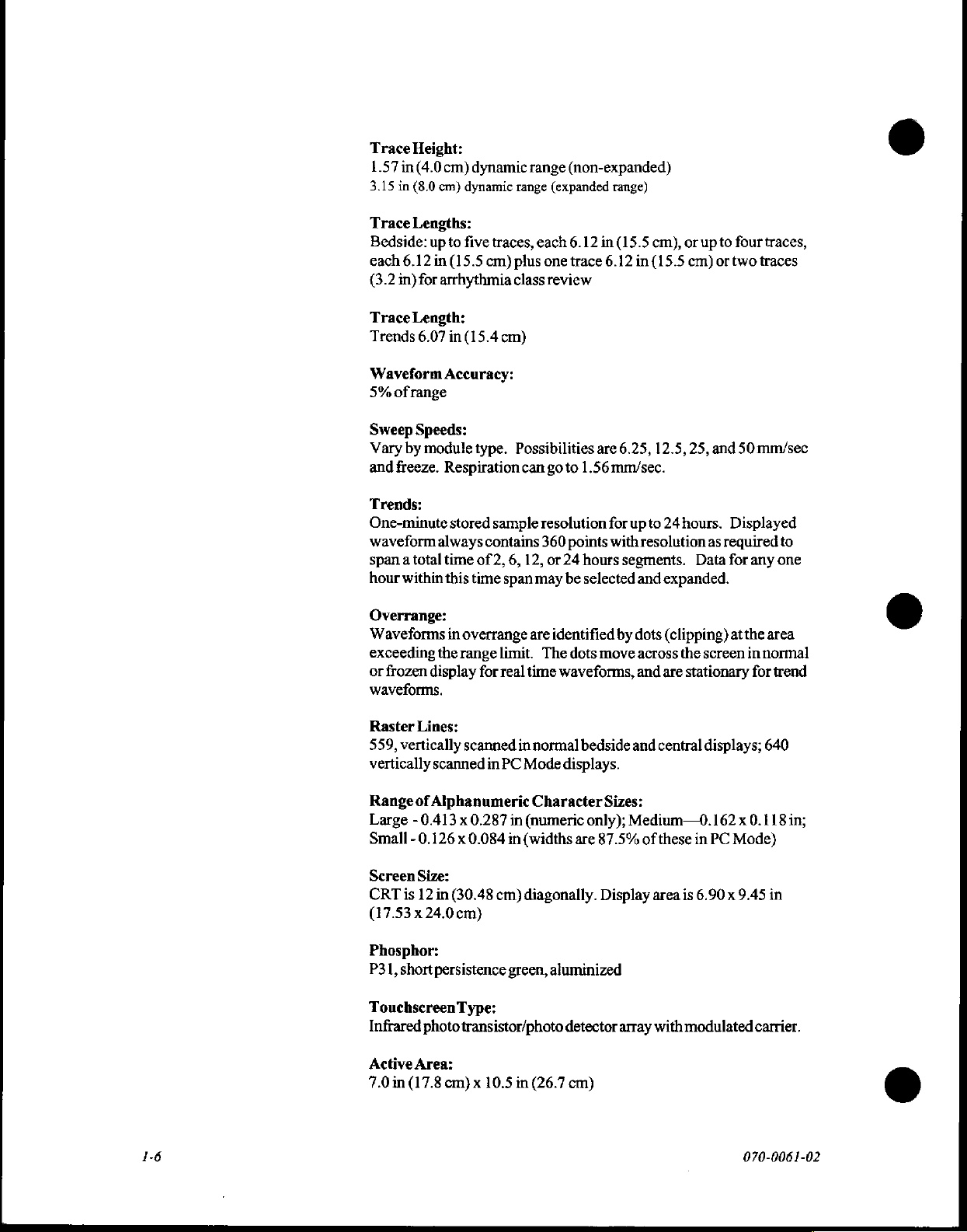
Trace
Height:
1.57
in(4.0cm)
3.15
in
(8.0
cm)
Trace
Lengths:
Bedside:
each
(3.2
Trace
Trends
Waveform
5%
Sweep
Vary
and
Trends:
One-minute
waveform
span a total
hour
up
6.12
in
in)
for
arrhythmia
Length:
6.07
of
range
Speeds:
by
module
freeze.
always
within
dynamic
dynamic
to
five
(15.5
in
(15.4
Accuracy:
Respiration
stored
time
this
range
traces,
cm)
plus
class
cm)
type.
Possibilities
can
sample
contains
of
2,
6,
time span
range
(non-expanded)
(expanded
each
6.12
one
trace
review
go
to
1.56
resolution
360
points
12,
or
24
hours
may
be
selected
range)
in
(15.5
6.12
are
6.25,
mm/sec.
for
upto
with
segments.
cm),
or
in
(15.5
cm)
12.5,
25,
24
hours.
resolution
Data
and
expanded.
upto
four
or
two
and
Displayed
as
required
for
traces,
traces
50
mm/sec
any one
o
to
Overrange:
Waveforms
exceeding
or
frozen
waveforms.
Raster
559,
vertically
vertically
Range
Large - 0.413 x 0.287
Small - 0.126 x 0.084
Screen
CRT
(17.53 х 24.0
Phosphor:
P31,
short
TouchscreenType:
Infrared
Active
7.0
in
in
overrange
the
range
display
Lines:
scanned
scanned
of
Alphanumeric
Size:
is
12
in
(30.48
ст)
persistence
photo
transistor/photo
Area:
(17.8
cm) x 10.5
for
in
are
limit.
The
real
time
in
normal
PC
Mode
Character
in
(numeric
in
(widths
cm)
diagonally.
green,
in
(26.7
identified
dots
waveforms,
displays.
aluminized
detector
cm)
move
bedside
Sizes:
only);
are
87.5%
Display
by
array
dots
(clipping)
across
the
and
are
stationary
and
central
Medium—0.
of
these
area
is
with
modulated
at
the
screen
in
normal
for
displays;
162 x 0.118
in
PC
Mode)
6.90 x 9.45
carrier.
ο
area
trend
640
in;
in
©
16
070-0061-02
Page 12
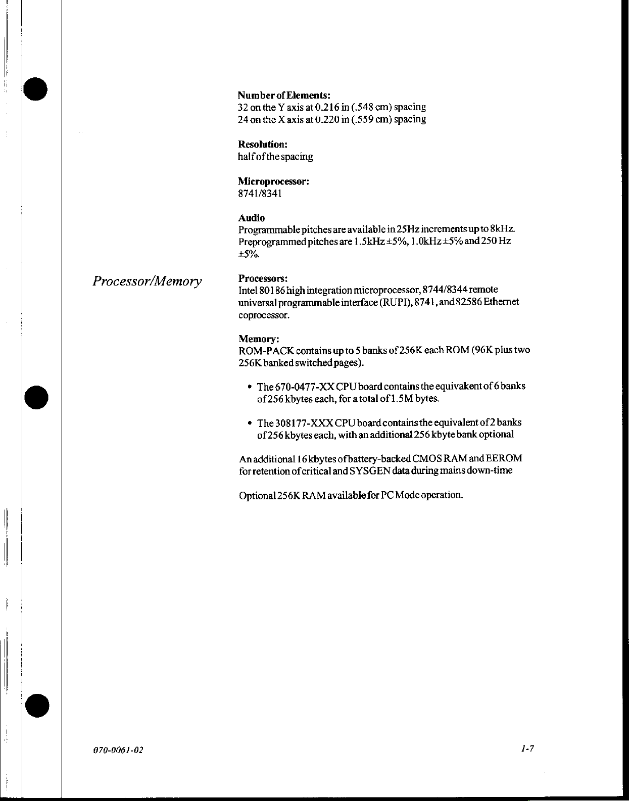
Number
32
24
Resolution:
half
Microprocessor:
8741/8341
Audio
Programmable
Preprogrammed
34500.
of
Elements:
onthe Y axis
on
the X axis
ofthe
spacing
pitches
at
0.216
at
0.220
are
pitches
in
(.548
in
(.559
available
are
1.5kHz+5%,
cm)
cm)
spacing
spacing
in
25Hz
increments
1.0kHz+5%
up
to
8kHz.
and 250
Hz
Processor/Memory
Processors:
Intel
80186
high
universal
coprocessor.
Memory:
ROM-PACK
256K
*
*
An
for
Optional
programmable
banked
The
of
The
of
additional
retention
switched
670-0477-XX
256
kbytes
308177-XXX
256
kbytes
of
256K
integration
contains
16
critical
RAM
up
pages).
CPU
each,
CPU
each,
kbytes
and
available
microprocessor,
interface
to 5 banks
for a total
with
ofbattery-backed
board
board
an
additional
SY
SGEN
for
(RUPT),
of
256K
contains
of
1.5M
contains
CMOS
data
during
PC
Mode
8741,
bytes.
256
8744/8344
and
82586
each
ROM
the
equivakent
the
equivalent
kbyte
bank
RAM
mains
operation.
remote
Ethernet
(96K
plus
of 6 banks
of 2 banks
optional
and
EEROM
down-time
two
070-006
1-02
1-7
Page 13

Page 14
©
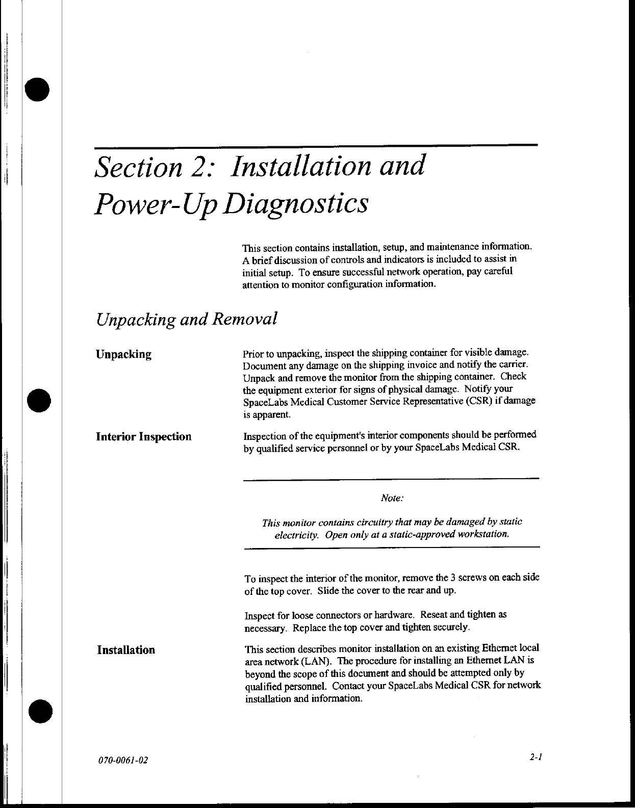
Section
2:
Power-Up
Unpacking
Unpacking
Interior
Inspection
and
Installation
Diagnostics
section
This
brief
A
setup.
initial
attention
Removal
to
Prior
Document
Unpack
equipment
the
SpaceLabs
apparent.
is
Inspection
qualified
by
contains
discussion
To
monitor
to
unpacking,
any
remove
and
Medical
the
of
service
installation,
controls
of
successful
ensure
configuration
inspect
damage
exterior
on
monitor
the
for
Customer
equipment's
personnel
the
the
signs
and
setup,
indicators
and
network
information.
shipping
shipping
the
from
physical
of
Service
interior
or
Representative
components
your
by
maintenance
and
included
is
operation,
container
invoice
and
shipping
damage.
SpaceLabs
information.
assist
to
careful
pay
visible
for
the
notify
container.
Notify
(CSR)
be
should
Medical
in
damage.
carrier.
Check
your
damage
if
performed
CSR.
|
|
©
Installation
070-0061-02
This
monitor
electricity.
inspect
To
of
the
Inspect
necessary.
This
area
beyond
qualified
installation
the
top
cover.
for
loose
Replace
section
network
scope
the
personnel.
and
describes
contains
Open
the
interior
(LAN).
of
Slide
the
connectors
the
top
monitor
The
document
this
of
Contact
information.
Note:
circuitry
only
cover
or
cover
procedure
that
at a static-approved
monitor,
your
remove
to
the
rear
hardware.
and
tighten
installation
for
should
and
SpaceLabs
may
be
damaged
workstation.
screws
3
the
and
up.
Reseat
and
securely.
existing
an
on
installing
an
attempted
be
Medical
by
static
each
on
tighten
Ethernet
Ethemet
CSR
as
only
for
side
local
is
LAN
by
network
2-1
Page 15
90303
B/903
11
B/90312B
PC
Bedside
Central
Monitor
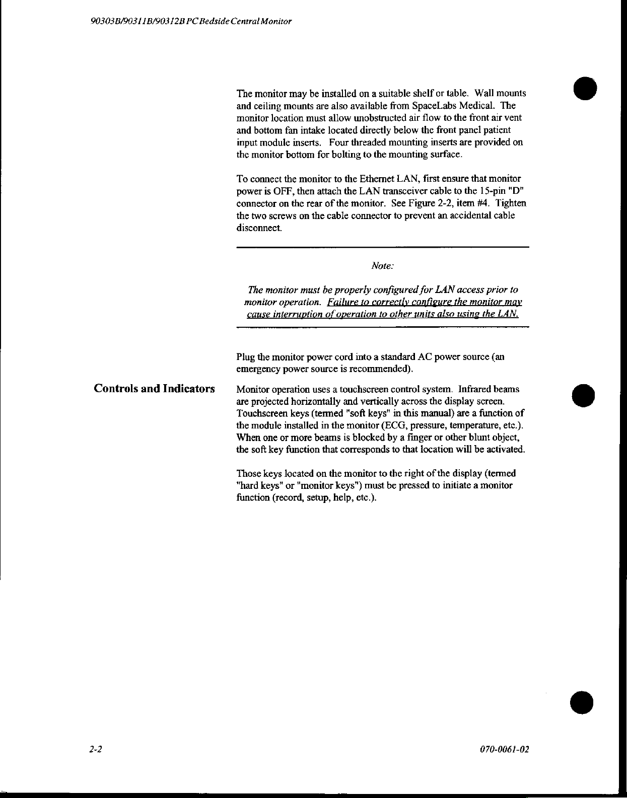
The
monitor
and
ceiling
monitor
and
input
the
To
power
connector
the
disconnect.
location
bottom
module
monitor
connect
is
OFF,
two
screws
The
monitor
monitor
cause
interruption
may
be
installed
mounts
fan
bottom
the
on
operation.
are
must
intake
inserts.
for
monitor
then
attach
the
rear
on
the
must
of
be
Failure
of
on a suitable
also
available
allow
unobstructed
located
Four
threaded
bolting
to
the
the
LAN
the
monitor.
cable
connector
properly
to
operation
from
directly
Ethernet
below
mounting
to
the
mounting
LAN,
transceiver
See
to
Note:
configured
correctly
to
other
shelf
or
SpaceLabs
air
flow
the
front
inserts
surface.
first
ensure
cable
Figure
2-2,
prevent
configure
for
LAN
units
an
also
table.
Wall
Medical.
to
the
front
panel
are
provided
that
to
the
item
#4,
accidental
access
the
monitor
using
mounts
The
air
vent
patient
monitor
15-pin
Tighten
cable
prior
may
the
LAN.
ο
on
"D"
to
Controls
and
Indicators
Plug
the
monitor
emergency
Monitor
are
projected
Touchscreen
the
module
When
the
soft
Those
"hard
function
power
operation
installed
one
or
key
function
keys
located
keys"
or
(record,
power
cord
source
is
uses a touchscreen
horizontally
keys
(termed
more
"monitor
setup,
in
the
beams
that
corresponds
on
the
keys")
help,
and
"soft
monitor
is
monitor
into a standard
recommended).
contro!
vertically
keys"
blocked
must
etc.).
across
in
this
(ECG,
by a finger
to
that
to
the
right of
be
pressed
AC
power
system.
the
display
manual)
pressure,
temperature,
or
other
location
the
display
to
initiate a monitor
source
(an
Infrared
are a function
will
beams
screen.
blunt
object,
be
activated.
(termed
etc.).
ο
of
2-2
070-0061-02
Page 16
Installation
and
Power-Up
Diagnostics
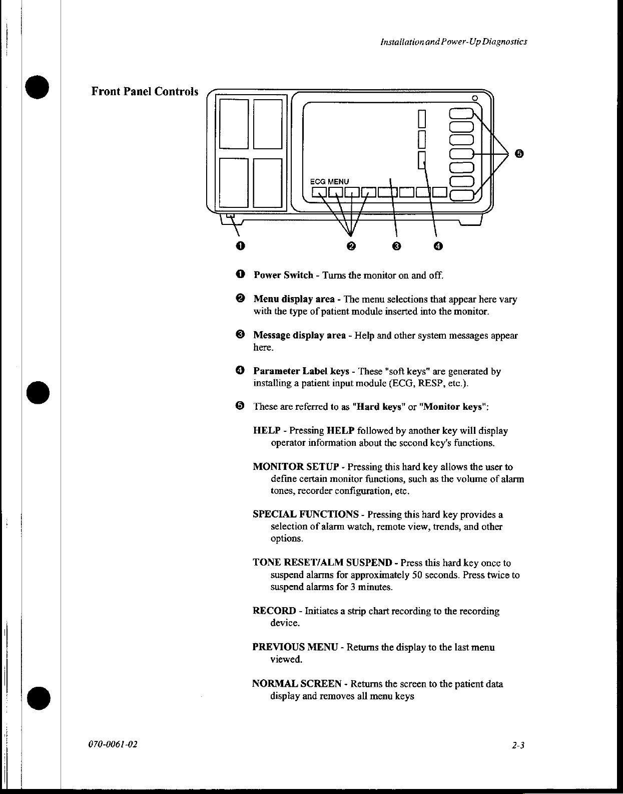
Front
Panel
Controls
Power
Menu
with
Message
here.
Parameter
installing a patient
DI
C
C
ECG
MENU
Switch - Turns
display
the
type
of
display
Label
area - The
the
patient
module
area - Help
keys - These
input
module
monitor
menu
inserted
and
"soft
on
and
selections
other
system
keys"
(ECG,
RESP,
off.
that
into
are
Co
I
appear
the
monitor.
messages
generated
etc.).
here
vary
appear
by
These
are
referred
HELP - Pressing
operator
MONITOR
define
tones,
SPECIAL
selection
options.
TONE
suspend
suspend
RECORD
device.
PREVIOUS
viewed.
NORMAL
display
information
SETUP - Pressing
certain
recorder
FUNCTIONS
of
alarm
RESET/ALM
alarms
alarms
-
Initiates a strip
MENU - Returns
SCREEN - Returns
and
removes
to
as
"Hard
HELP
followed
about
monitor
configuration,
functions,
-
Pressing
watch,
remote
SUSPEND - Press
for
approximately
for 3 minutes.
chart
all
menu
keys”
or
by
another
the
second
this
hard
such
etc.
this
view,
recording
the
display
the
screen
keys
"Monitor
key's
key
as
hard
trends,
this
50
seconds.
to
to
to
keys":
key
will
functions.
allows
the
the
volume
key
provides
and
hard
key
Press
the
recording
the
last
menu
the
patient
display
user
to
of
alarm
a
other
once
to
twice
data
to
070-0061-02
2-3
Page 17
90303
B/903 1 1B/90312B
PC
Bedside
Central
Monitor
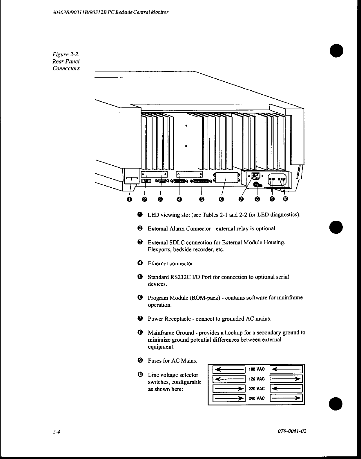
Figure
Rear
2-2.
Panel
Connectors
ое
LED
0
viewing
© © 0 6 8 6
slot
(see
Tables
2-1
and
2-2
for
LED
diagnostics).
External
External
Flexports,
Ethernet
Standard
devices.
Program
operation.
Power
Mainframe
minimize
equipment.
Fuses
Line
switches,
as
Alarm
SDLC
bedside
connector.
RS232C
Module
Receptacle - connect
Ground - provides a hookup
ground
for
AC
voltage
shown
selector
configurable
here:
Connector - external
connection
recorder,
I/O
(ROM-pack) - contains
potential
Mains.
for
etc.
Port
for
to
differences
External
connection
grounded
relay
is
optional.
Module
to
optional
software
AC
mains.
for a secondary
between
external
Housing,
serial
for
mainframe
ground
©
to
070-0061-02
Page 18
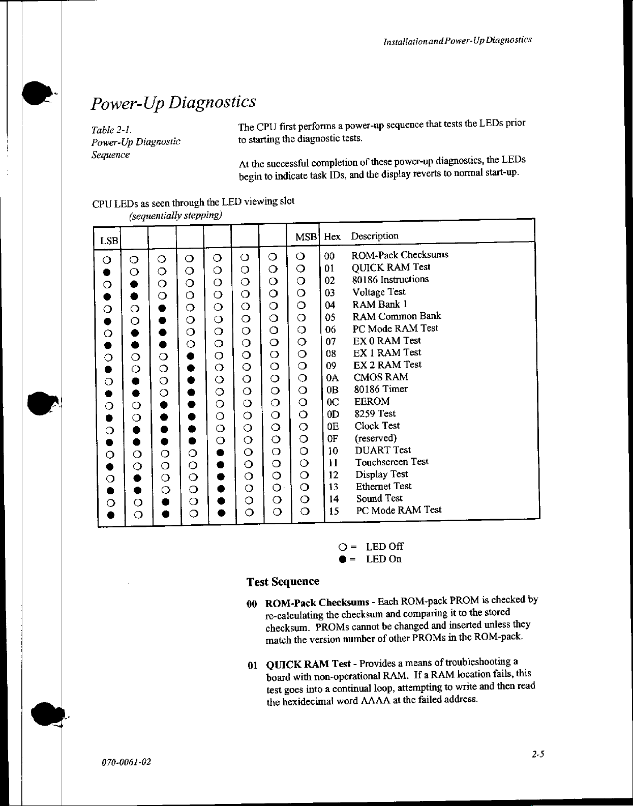
Power-Up
2-1.
Table
Power-Up
Sequence
CPU
LSB
Diagnostic
LEDs
(sequentially
000600000900000000000600
Diagnostics
through
seen
as
stepping)
0000000000000
000000000
00000000000000600096000
performs
first
CPU
The
diagnostic
starting
to
At
begin
viewing
LED
the
0000000000000000000000
00000066888889800000000
the
successful
the
indicate
to
slot
0000000000000000000000
0000000000000000000000
completion
task
Hex
SB]
=
00
0000000000000000000000
IDs,
01
02
03
04
05
06
07
08
09
0A
OB
oC
OD
OE
OF
10
11
12
13
14
15
power-up
a
tests.
Installation
sequence
power-up
these
of
display
the
and
Description
ROM-Pack
QUICK
80186
Voltage
RAMBankl
RAM
PC
EX
EX
EX
CMOS
80186
EEROM
8259
Clock
(reserved)
DUART
Touchscreen
Display
Ethernet
PC
RAM
Instructions
Test
Common
Mode
RAM
0
RAM
1
RAM
2
RAM
Timer
Test
Test
Test
Test
Sound
Mode
RAM
Test
Test
and
that
diagnostics,
reverts
Checksums
Test
Bank
Test
Test
Test
Test
Test
Test
RAM
Power-Up
the
tests
normal
to
Diagnostics
prior
LEDs
LEDs
the
start-up.
ο
070-0061-02
Test
Sequence
ROM-Pack
00
re-calculating
checksum.
the
match
QUICK
01
with
board
goes
test
hexidecimal
the
O=
@=
Checksums
checksum
the
PROMs
version
RAM
non-operational
into
cannot
number
-
Test
continual
a
word
LEDOff
LEDOn
Each
-
and
be
other
of
Provides
RAM.
loop,
AAAA
ROM-pack
comparing
PROMs
means
If
failed
the
a
and
of
RAM
changed
a
attempting
at
checked
PROM
it
inserted
in
troubleshooting
to
address.
is
stored
the
to
unless
ROM-pack.
the
location
and
write
fails,
then
by
they
a
this
read
2-5
ООО
Page 19
90303B/903 1 1B/90312B
PC
Bedside
Central
Monitor
02
80186
instructions
03
Voltage
main
04
RAM
then
05
RAM
of
patterns
valid.
06
PCMODE
PCMODE
07
EX
patterns
valid.
Instructions
for
Test
-
board
CPU
Bank
1
-
read
to
verify
Common
and
RAM
RAM
0
RAM
Test
and
then
-
Checks
internal
Checks
Bank
then
and
that
Bank
read
Test
tested
is
-
Extra
read
the
the
1
RAM
the
-
-
to
some
problems.
lithium
logic
+5V
is
filled
patterns
Common
to
This
by
bank
verify
verify
test
Test
O
RAM
that
bank
that
is
15.
of
the
80186
back-up
supply.
written
currently
the
with
RAM
the
pattern
is
filled
pattern
battery
a
remains
resident
located
set
of
patterns
valid.
is
filled
written
non-functional.
with
a
written
and
with
remains
set
of
remains
on
a
ο
the
set
08
EX
pattems
valid.
09
EX
patterns
valid.
0A
CMOS
initialized.
verify
initialize
0B
80186
Failures
80186
0C
EEROM
CMOS
the
0D
8259
DE
Clock
OF
(reserved)
I
RAM
and
2
RAM
and
RAM
it
is
flag
Timer
are
itself.
-
Performs
Test
Test
Test
then
Test
then
-
CMOS
It
it
has
still
correct.
is
set,
-
Checks
usually
RAM
-
Tests
-
Verifies
currently
Not
-
-
Extra
read
-
Extra
read
to
been
and
caused
a
checksum
(Test
the
8259
operation
bank
1
RAM
to
verify
that
bank
2
RAM
verify
that
is
checked
initialized,
If
not,
then
the
checksum
timer
functions
by
inputs
in
0A).
interrupt
of
used.
is
filled
the
pattern
is
filled
the
pattern
to
determine
the
checksum
CMOS
the
controller.
the
is
is
calculated
present
to
the
80186
same
manner
real-time
with
a
written
with
a
written
if
it
has
is
checked
cleared,
and
in
the
80186.
rather
as
clock
chip.
set
of
remains
set
of
remains
been
the
stored.
than
used
ο
to
the
for
2-6
10
DUART
Test
-
Tests
communications
with
the
serial
port.
070-0061-02
Page 20
11
Touchscreen
processor
marginal(degraded)
detector/emitter
"Single
display
The
even
and
beam
reverts
monitor
single-beam
a
with
Test
-
Checks
each
touchscreen
settings.
failure
failure
-
to
normal
and
touchscreen
the
is
indicated
touch
both
monitor
failure.
Installation
infrared
sensor
under
If
only
one
along
sides
operation
will
typically
and
Power-Up
touchscreen
normal
beam
is
broken,
with
the
message
for
touch
analyzer".
within
remain
Diagnostics
8741/8341
and
then
The
5
seconds.
functional
Ifmore
indicated
analyzer
12
Display
verify
13
Ethernet
that
also
14
Sound
to
15
PCMODE
various
than
2
beams
on
the
within
Test
-
Checks
the
CPU
Test
-
it
is
communicating
run.
Test
-
Verifies
instructions,
RAM
patterns
are
broken,
screen
and
the
seconds.
5
display
is
communicating
Checks
and
Test
then
the
with
that
-
The
read
Ethernet
the
PCMODE
then
display
memory
with
the
80186.
sound
to
verify
detector/emitter
reverts
display
82586
chip
the
to
the
to
verify
operation
memory.
processor
A
self-diagnostic
is
responding
RAM
is
filled
patterns.
touchscreen
failure
and
to
verify
test
properly
with
is
to
is
070-0061-02
Page 21
cen
90303B/90311B/90312B
Table
2-2.
Mainframe
Test-Failure
CPU
LSB
Diagnostic
Codes
seen
as
LEDs
(blinking)
0000900090009000000
00000090
0000
9000000000000000000000000000000000
D00
PC
through
OO
〇
OOOOOO
〇
OOO@@@@
〇
OOO@@@@
〇
OOO@@
〇
Oe@@OOO@@@
Bedside
OOOO@@@@@@@@
〇
O@@@
〇
Central
LED
the
V000000000000000000000000000000000
eOOOOOO@@@
Monitor
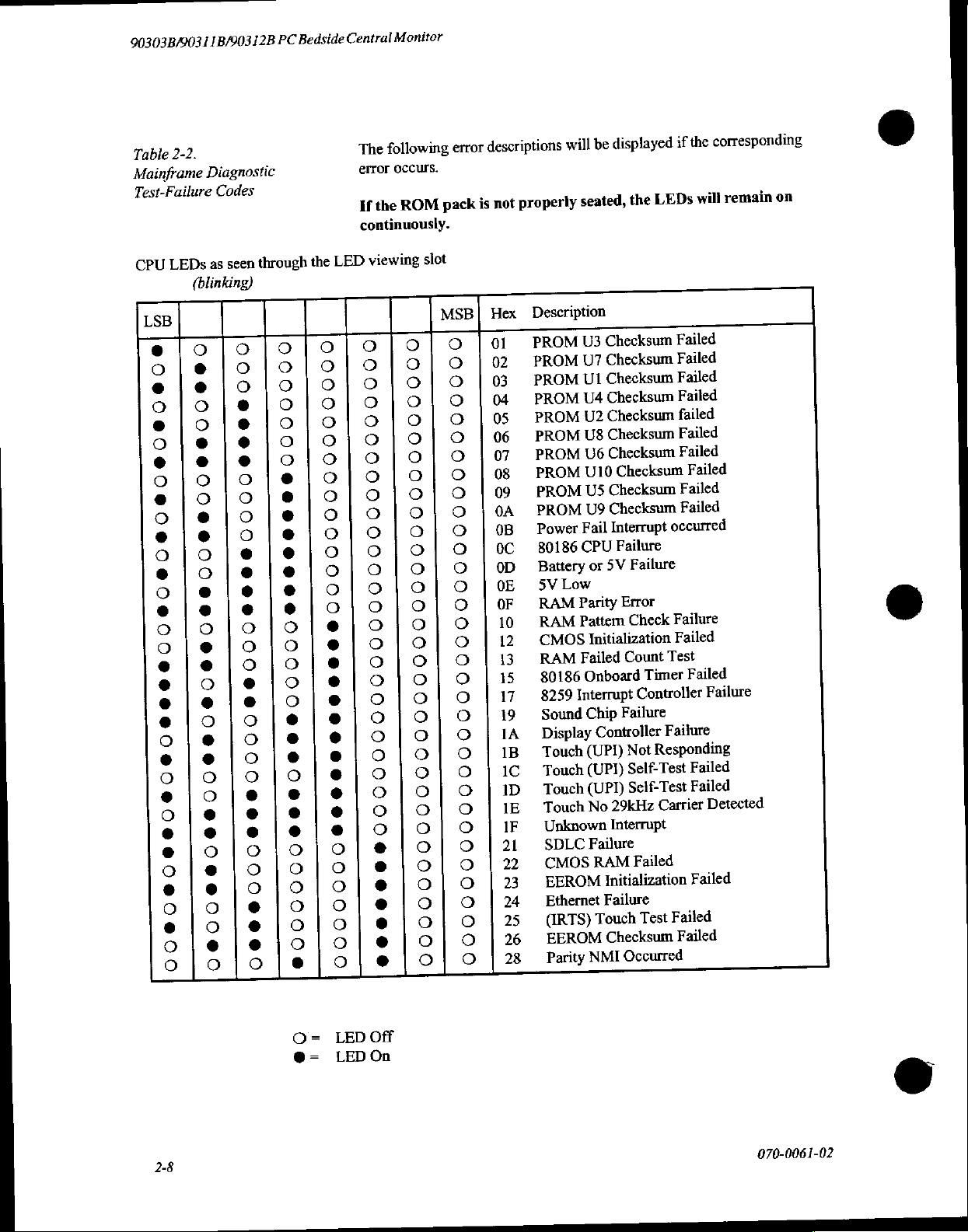
following
The
error
occurs.
ROM
the
If
continuously.
viewing
0000000000000000000000000000000000
error
pack
slot
MSB
0000000000000000000000000000000000
corresponding
the
descriptions
properly
not
is
Hex
01
02
03
04
05
06
07
08
09
0A
0B
oc
0D
DE
OF
10
12
13
15
17
19
1A
1B
IC
ID
IE
IF
21
22
23
24
25
26
28
0000000000000000000000000000000000
will
seated,
Description
Checksum
PROM
PROM
PROM
PROM
PROM
PROM
PROM
PROM
PROM
PROM
U3
U7
UI
U4
U2
U8
U6
U10
US
U9
Fail
Power
80186
CPU
Battery
5V
Low
RAM
Parity
Pattern
RAM
CMOS
Failed
RAM
Onboard
80186
Interrupt
8259
Sound
Chip
Display
(UPI)
Touch
Touch
Touch
Touch
Unknown
SDLC
CMOS
EEROM
Ethernet
(IRTS)
EEROM
Parity
Checksum
Checksum
Checksum
Checksum
Checksum
Checksum
Checksum
Checksum
Interrupt
or
5V
Initialization
Controller
(UPI)
(UPI)
29kHz
No
Interrupt
Failure
RAM
Initialization
Failure
Touch
Checksum
NMI
the
Checksum
Failure
Failure
Error
Check
Count
Failure
Not
Self-Test
Self-Test
Occurred
displayed
be
if
will
LEDs
Failed
Failed
Failed
Failed
failed
Failed
Failed
Failed
Failed
Failed
occurred
Failure
Failed
Test
Failed
Timer
Controller
Failure
Responding
Failed
Failed
Carrier
Failed
Failed
Failed
Test
Failed
remain
Failure
Detected
on
2-8
Oz
LED
LED
Off
On
070-0061-02
Page 22
©
Section
3:
Block
Diagrams
Troubleshooting
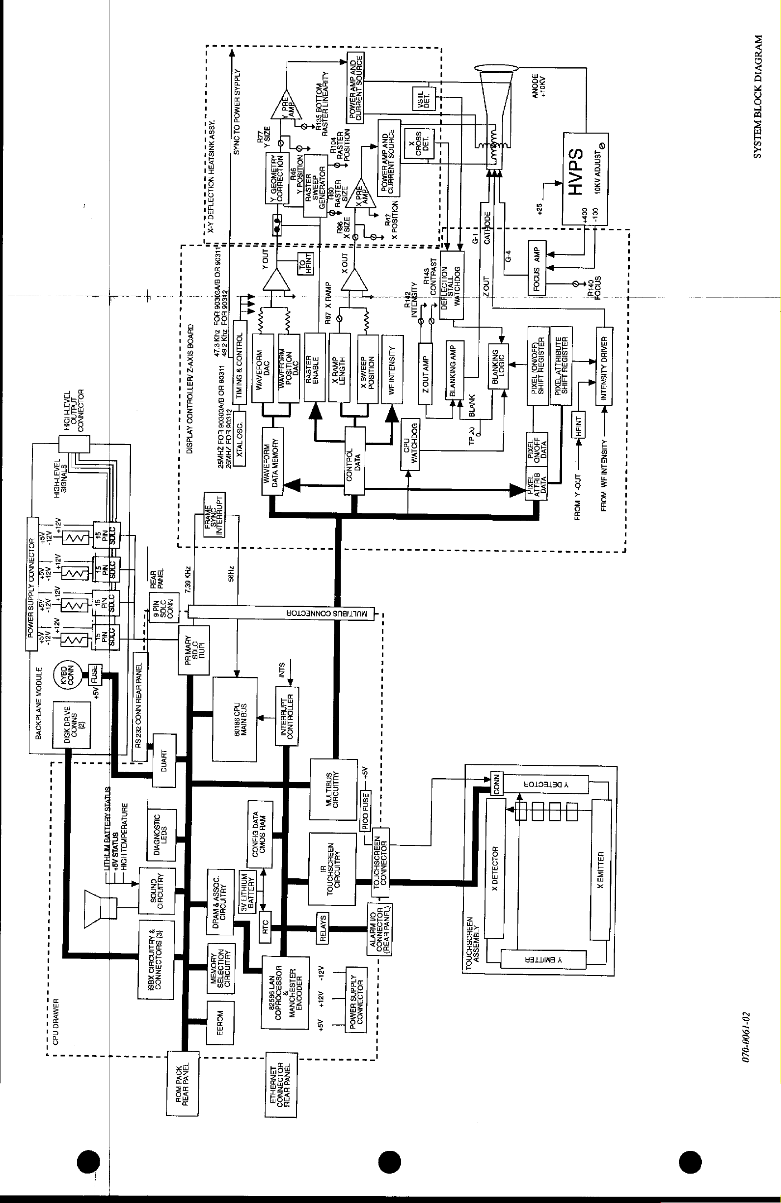
The
System
Block
following
theory
of
Appendix A for
assembly
The
PC
driving
handling
specific
Patient
handle
parameter
tothe
four
Remote Module
discussions
operation,
complete
part
numbers.
Bedside
up
functions
input
microprocessor-based
to
six
patient
and
display
modules
single-high
modules
are
based
calibration,
input
characteristics.
are
entirely
plug
modules
can
be
Housing.
and
assembly
modules.
separate
into
the
(refer
monitored
and
on a block
troubleshooting.
drawings.
patient
The
Module-specific
and
module
to
via a rear
level
Refer
monitor
monitor
are
software
backplane,
Figure
3-1).
panel
approach
Referto
to
Appendix
is
capable
has
generic
and
monitor-
driven.
whichcan
Two
additional
SDLC
connector
to
the
of
data-
B for
070-006
1-02
Patient
on-board
monitor
This
inmemory.
memory
pack provides
(biomed)
Refer
operation
interface
data
processor
via a synchronous
data
is
(DRAM)
and
to
the
of
to
is
collected
in
processed
The
main
for
program
monitor
Isolation
user
enable
Diagnostics
diagnostics.
access
and
converted
each
patient
data
by
the
CPU
temporary
software
diagnostics
to
input
link
monitor
contains
storage
and
are
part of
Data
other
elements
into a digital
module
control
CPU
on-board
of data. A removable
the
operating
included
this
is
communicated
and
(SDLC)
acting
dynamic
in all
section
on
the
on
system.
network.
format
through
transmitted
bus.
instructions
random
ROM-packs.
for
details
via
ROM-
User
an
Ethernet
access
on
the
to
the
stored
3-1
Page 23
90303B/90311B/90312B
PC
Bedside/Central
Monitor
Isolation
Diagnostics
Alluser
displayed
"hard
monitored
perimeter
operator
Displayed
the
display.
Power
international
voltages
are
+25
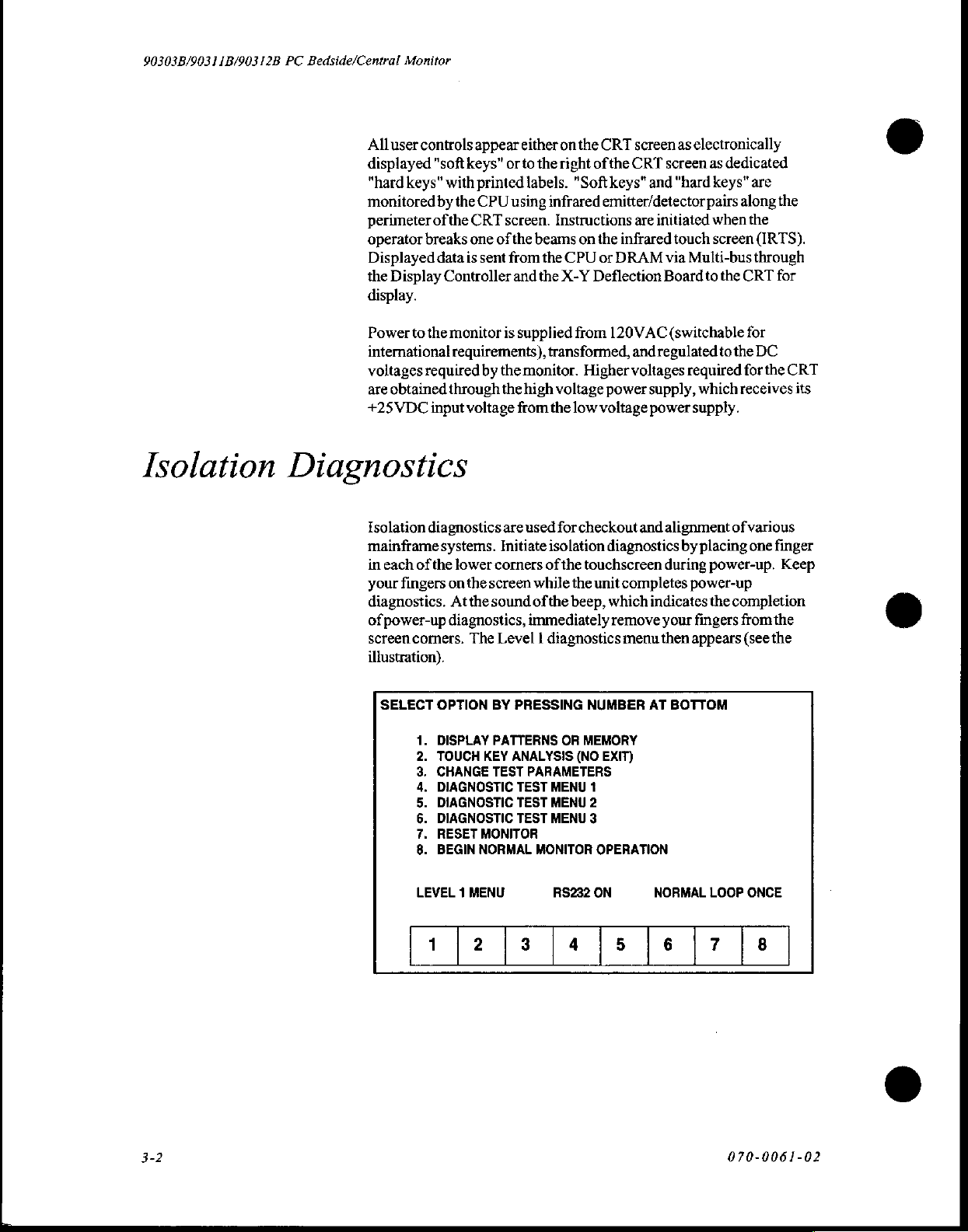
Isolation
mainframe
in
your
diagnostics.
of
screen
illustration).
controls
"softkeys"
keys"
by
of
breaks
data
Display
to
the
required
obtained
VDC
input
diagnostics
systems.
each
of
the
fingers
power-up
corners.
with
the
the
is
Controller
monitor
requirements),
through
voltage
lower
on
the
Atthe
diagnostics,
appear
either
on
orto
the
right
printed
CPU
CRT
one
The
labels.
using
infrared
screen.
of
sent
from
is
by
the
the
are
Initiate
corners
screen
sound
Level I diagnostics
Instructions
the
beams
the
CPU
and
the
X-Y
supplied
transformed,
monitor.
high
voltage
from
the
used
for
isolation
of
the
while
of
the
beep,
immediately
the
CRT
screen
ofthe
CRT
"Soft
keys"
and
emitter/detector
are
initiated
on
the
infrared
or
DRAM
Deflection
from
120VAC
and
regulated
Higher
voltages
power
supply,
low
voltage
checkout
touchscreen
the
unit
power
and
diagnostics
completes
which
indicates
remove
menu
as
electronically
screen
as
dedicated
"hard
keys"
pairs
when
touch
screen
via
Multi-bus
Board
to
the
(switchable
to
the
required
which
supply.
alignment
by
during
your
then
of
placing
power-up.
power-up
the
completion
fingers
appears
are
along
the
the
(IRTS).
through
CRT
for
for
DC
for
the
CRT
receives
various
from
(see
one
its
finger
Keep
the
the
©
ο
SELECT
mo
wn
PNOAP
LEVEL 1 MENU
OPTION
DISPLAY
TOUCH
CHANGE
DIAGNOSTIC
DIAGNOSTIC
DIAGNOSTIC
RESET
BEGIN
BY
PRESSING
PATTERNS
KEY
ANALYSIS
TEST
TEST
TEST
TEST
MONITOR
NORMAL
NUMBER
OR
MEMORY
(NO
PARAMETERS
MENU
1
MENU
2
MENU
3
MONITOR
RS232
AT
EXIT)
OPERATION
ON
BOTTOM
NORMAL
LOOP
ONCE
3-2
070-0061-02
Page 24
|
|
|
]
i
TSASTHSIH
INdINO
ATHBIH
FIVNDIS
~
|
|
HOLOJNNO3
已
|
AGIT
AZ
S+
HO19
に
ми
ヨ
NNOO
Ag
s+
に
AJddnS
ми
|
Ag
As
に
H
ヨ
ола
|
AOd
ме-
Ast
CBA
IMNAON
INVIAMOVE
NNOO
3180
SNNOO
ASIO
fa
2
Nid
st
Nid
οι
EN
Nid
Nid
si
seng
last
=
十
i
va
Nive
NNOO
2709
ニー
ニー
ニー
ニー
ニニ
ニニ
ニニ
ニー
ニー
ニー
ニニ
ニー
ニニ
ニニ
ニ
ニー
ニコ
ans
AS
Mas.
|
|
|
t
一
-|
208
TawddvauNNoozezsd
!
1
Tk
'ASSV
ANISIV3H
NOLLO31430
AX
¡y
ù
111206
I
トー
ニー
ニ
ニ
ニー
コ
ーー
ニー
i
i
HOJ
GHVOE
ZUM
E
ZP
SIXV-Z
НО
9//Е0506
ぐ
C06
OS
2UN
ぞ
@Y
11606
/HATIOHLNOO
HO
H/VEOEOS
AVTdSIQ
HO
ZHASE
1dnBH
A3
ONS
|
ヨ
INI|
|
1
|,
1
|
!
zHM662
|
し
Advi
2709
1904
1
1
|
자
AlddAS
HAMOd
OL
ONAS
—и_
1
!
-
21806
HOJ
ZANSZ
|
2H95
|
WHO44AVA
sat
'
'
1
azsa
이입
©-
ODA
NOLLOJHHOD
u
“Lan
i
osos.
Hoya
ova
AYONZN
OA
VIVO
4
!
1
1
9
SIN
|
HI
1dndBBIN
TIOHINCO
ㅣ
!
!
ㅣ
OILIOG
4
SEiH
à
@
NOILSOd
Е
H3LSVH
d33MS
À
SAVE
-
X
208
sas
ova
i
t
1
;
Е
п
3
2
1
由
т
1
'
AHHVN
VAN]
vs
NOHISOd
dalsve
É
HOLYHAN35
HASVH
3219
EN
|
32ISX
968
|
i
Let
d33MS
dAVYX
HLON31
X
JotilNOO
viva
'
1
o
5
E
i
=
1
1
!
1
JOHNOS
ANV
diNV
INZHHNO
EMO
NOILISOd
tra
X
ALISNALNÍ
3M
4
1
上
U
=
1
LH
Add
1
[
NOILISOd
1
=
ro
i
'
1
TT
‘130
VISA
SSOHO
‘130
x
FINI
EIA
1SYHINO|
NOLLOJ
erly
Ee
Had
te
mos
div
IN
|
5OqHOIVA
!
!
1
1
reo
1
>
DOGHOLÝM
|
|
MNYJ8|
4
ha
özde
'
1
;
ONDINYTA
'
dv
ONIINVIE
feb
1
'
1
1
!
el
21901
|
!
300NY
AOL
st
1
1
|
aww
snaos
|}
HALSID3E
HONO)
LIIHS
EX
ld
73700
ONO
VIVO
1
1
i
1
SdAH
to
Oof+
!
!
1
'
i
3100818110
ΗΞΙΕΙΟ3Η
73300
1415.
4no-
人
NOH4
1
1
!
i
Pisnravaxo
cor
!
prnl
1
Sagt
|
.
i
H3AIHQ
ALISN
ヨ
1NI
ALISN
ヨ
1NE
aranan
コ
WOH
1
1
WVUDVIA
NOOTE
NILSAS
|
1Hvna
L-----------------------
1
!
t
1
1
-8wvdqndo
УВМУНА
Пао
i
i
1
1
1
1
1
ΠΠ.
1
!
1
ΒΗΩΙΝΗΒαΙΝΞΙ
OLLSONOVIA
SPLVLS
ΗΘΙΗ
AS+
aNnos
5
ABHITOHIO
XBS!
5
!
'
‘
5037
AHJInoHIO
1E)
SHOLOZNNOO
1
TaNva
2OVd
。
20SSV
ABLINOHIO
AVHQ
NBS
ABONA
ES
woua3
'
;
|
i
vlvq
5HNOO
И
!
1
SNEILINN
Av
SORO
244
8055300Hd00
2
HOLOSNNOO
ΙΗΝΗΞΗΙ3
H
ヨ
HICOONI
JS
ヨ
HONVW
1
!
Nd
出
SAVIAH
AZ
Ağ
AS
1
ano
N33HOSHONOL
|
1
As+
一
mz
snd
oola
N33H9SHONOL
HOLOJNNOJ
AHLINOBIO
HOLOJNNOJ
On
WHY
IV
|
|
|
—
=
KIdANS
=
HOLIANNOO
--
ーー
HIMOd
ニー
ニー
-
ニー
ニー
1
i
!
OaNvd
dv3d)
NI3HOSHONOL
ヨ
SSV
x
AIBW
5
니그
y
40193130
2
3
m
9
3
8
O
|
다
2
o
<
A
。
X
HALL
20-1900-020
n
WOH
Hvau
vau
©
Page 25
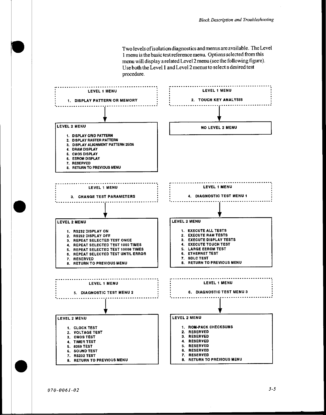
Two
levels
of
1
menu
is
the
menu
will
display
Use
both
the
procedure.
isolation
basic
Level 1 and
diagnostics
test
reference
arelated
Block
and
menu.
Level 2 menu
Level 2 menus
Description
menus
are
available.
Options
(see
to
selected
the
following
select a desired
and
Troubleshooting
The
from
this
figure).
test
Level
DISPLAY
LEVEL 2 MENU
DISPLAY
DISPLAY
DISPLAY
DRAM
aon
CMOS
EEROM
RESERVED
RETURN
SNA
3.
LEVEL 2 MENU
RS232
RS232
REPEAT
REPEAT
PONS
REPEAT
REPEAT
RESERVED
RETURN
PNT
LEVEL 1 MENU
GRID
RASTER
ALIGNMENT
DISPLAY
DISPLAY
DISPLAY
TO
LEVEL 1 MENU
CHANGE
DISPLAY
DISPLAY
SELECTED
SELECTED
SELECTED
SELECTED
TO
PATTERN
PATTERN
PATTERN
PREVIOUS
TEST
ON
OFF
PREVIOUS
OR
MEMORY
PATTERN
MENU
PARAMETERS
TEST
ONCE
TEST
1000
TEST
10000
TEST
UNTIL
MENU
25/26
TIMES
TIMES
ERROR
4.
LEVEL 2 MENU
EXECUTE
EXECUTE
EXECUTE
EXECUTE
eons
LARGE
ETHERNET
SDLC
RETURN
SNe
LEVEL 1 MENU
2.
TOUCH
NO
DIAGNOSTIC
EEROM
TEST
KEY
ANALYSIS
LEVEL 2 MENU
LEVEL 1 MENU
TEST
ALL
TESTS
RAM
TESTS
DISPLAY
TOUCH
TO
TESTS
TEST
TEST
TEST
PREVIOUS
MENU
MENU
1
LEVEL 1 MENU
5.
DIAGNOSTIC
LEVEL 2 MENU
CLOCK
TEST
VOLTAGE
CMOS
TEST
TIMER
TEST
8259
TEST
SOUND
TEST
AS232
TEST
RETURN
suoyapap
070-0061-02
TO
TEST
TEST
PREVIOUS
MENU
MENU
LEVEL 1 MENU
6.
ROM-PACK
RESERVED
pp.
RESERVED
RESERVED
RESERVED
RESERVED
RESERVED
RETURN
SAIs
DIAGNOSTIC
TO
2
LEVEL 2 MENU
TEST
CHECKSUMS
PREVIOUS
MENU
MENU
3
Page 26
90303B/90311B/90312B
PC
Bedside/Central Monitor
When
displayed
code
number
TEST
message.
Ifa
failure
The
first
1.
Display
and
and
diagnostic
in
the
is
FAILED
Failure
failure
occurs during
message
indicating
three
Level I menu
Pattern
alignment
ROM.
tests
are
lower
left
replaced
by
message
codes
are
is
displayed
the
specific
or
Memory:
ofthe
run,
an
comer
the
failure
is
also
displayed
described
Note:
the
touch
location
selections
CRT
and
ID
code
of
the
CRT.
code.
above
in
Table
key
analysis
above
the
and nature
are
Provides
allows
viewing
for
the
test
Ifa
failure
ATEST
the
2-2.
test
TEST
FAILED
ofthe
described
test
patterns
the
in
progress
occurs,
PASSED
RS232
ON
(Option
message
error.
below.
for
checkout
contents
is
the
or
2),
of
RAM
ID
the
2.
in
Most
long
3.
TouchKey
display
broken
this
this
Change
limits
or
selection.
test.
90303
monitors
axis
despite
Test
of
Level 2 tests.
Analysis:
of+'s
or
-'s.
always
show
The
the
two
on,
respectively).
mainframe
utilize
X1
-X48
adjacent
Parameters: Use
Fingermovement
These
indicate
Note:
only
24
indications.
beam-broken
beam
There
must
be
vertical-pointing
Breaking
this
menu
around
status
isno
powered
indicators.
to
select
the
screen
results
(i.e.,
beam
Level 2 menu
down
to
exit
beams
across
asingle
the
beam
frequency
for
from
the
will
3-6
070-0061-02
Page 27

Block
Description
Troubleshooting
and
Power
Overview
Supply
power
The
*
the
the
the+/-12
the
the
.....
the
passing
After
switch,
power
transformer
power
convert
output
swing).
Width
Pulse
100kHz
outputs.
The+5VDC
+
Module
+12VDC
provides
compatible
board).
outages
any
minimum
a
the
MOSFET)
the
consists
supply
AC
Miscellaneous
uninterruptible
VDC
+/-5
DC-to-DC
VDC
Power
Switch
12V
battery
power
transformer
through
fuses,
approximately
itto
from
varies
+24VDC
This
Modulator-typeregulators,
signal,
clock
and
bucket
also
power
for
+5
The
switching
by
and
loss
data
of
predetermined
trips
of
Board
board
line
the
input
and
this
steps
17
about
voltage
convertit
+/-12VDC
and
(A6),
the
feeds
306440-type
for
monitors
logic
VDC
to
user
minutes
5
discharge
arelay
power
EMI
voltage
voltage
+24VDC
31
to
is
the
CRT
that
a+12V
reinitialization.
(typically
disconnect
to
following
power
converter
filter,
selector
down,
(under
depending
volts
to
sent
regulated
to
outputs
Display
filament
Z-axis
Z-axis
have
is
output
lead/acid
is
level
elements:
supply
input
AC
the
switches.
bridge
the
actual
the
load,
line
on
supply
power
the
synchronized
+/-12,
+/-5,
CPU
the
feed
Controller
andthe
boards
maintained
Expected
minutes
10
reached,
battery.
the
board.
fan.
(backward
circuitry
during
battery.
battery
or
solid
a
the
to
goes
the
Once
voltage
voltage
where
on-board
an
+60VDC
and
board
-5V
The
separate
a
on
AC
prevents
This
state
and
(A1),
The
power
runtime
When
switch
rectifier
to
longer).
filter
three
the
supply
is
(a
070-0061-02
The+60VDC
*
-9VDC,
deflection
X-Y
battery
Supply
operation.
CRT
Alloutputs
12VDC
are
and
regulator
+18VDC,
board
charger.
(A10),
5VDC
The
which
protected
supplies
also
+/-25
and
(A3).
VDC
+25
produces
against
are
produces
output
VDC
VDC
+18
The
powers
-100V,
circuit
short
protected
also
semi-regulated
voltages
used
is
High
the
+400V,and+100KV
overload.
and
from
+/-8VDC,
power
to
power
to
Voltage
overvoltage.
the
the
Power
for
The
3-7
Page 28
90303B/90311B/90312B
PC
Bedside/Central
Monitor
The
power
bus
voltage
istoo
«
awarning
low
toaninsufficient
*
apower-fail
brown-out
monitor
ortoo
signal
(WARN/)
input
(PFAIL/)
has
occurred,
keeps
high.
voltage
to
the
It
also
ifthe
warn
and
power
issues
+5VDC
the
CPU
that
battery
supply
the
following
is
that a power
operation
shut
offif
about
the
input
messages:
to
drop
outage
is
in
effect.
out
or
©
due
AC
Input
Assembly
Input
115
vac
(220
vac
International)
Outputs
+
+24VDC
»
Battery
Inputs
+
+24VDC
the
«
SYNC:47.3KHzsync
Controller
Start-Up
*
required
*
seriesregulator
*
providesapproximately
+5
VDC
*
power
approximately
5
runs
*
protection
*
produces
*
produces
*
Only
(unregulated)
Enable
(Switched
(unregulated)
Unregulated
(49KHz
Control
DC/DC
at
Power
before
the
(U100)
Converter
input
torun
15
approximately
circuit
the
+/-5VDC
15
VDC
regulator
that
to
Power
+24VDC).
from
Power
Bus.
for
Pulse
FOR
90312B).
Pulse
Width
IC
12
volts
IC
is
approximately
VDC
once
the
100kHz
is
activated
regulated
house-keeping
is
backed-up
Supply
AC
Input
Assembly.
Width
Modulators
Notused.
Modulator
12VDC
converter
switching
at
6.5
VDC
voltages.
supply
by a (sealed)
PCBA
via
ICs
can
to
is
up
andrunning.
frequency
output.
voltage.
Lead-acid
J-3.
Referred
from
Display
begin
running.
start
and
battery.
to
as
O
+12
VDC
*
+12VDC
¢
PFAIL/
Power
Up
¢
Over-Voltage
if
+24V
*
PFAIL
15v.
+
SHUTDOWN
below
+
WARN
failure.
DC/DC
Converter
Overvoltage
shuts
and
Shutdown
exceeds
shuts
down
9.5VDC.
isa
Four-State
Occurs
this
regulator
Control
Shutdown
38 + 2VDC
all
supplies
shuts
down
3mSec
before
Protection
shuts
down
down
circuit
during
except
+/-5
VDC
signal
sent
to
shutdown.
setat
loss
both
Pulse
+/-5V
power
inform
14
volts.
of
AC
Width
if
+24V
supply
the
CPU
Mains.
Modulators
drops
below
if+24V
drops
of
power
070-0061-62
Page 29
Block
Description
and
Troubleshooting
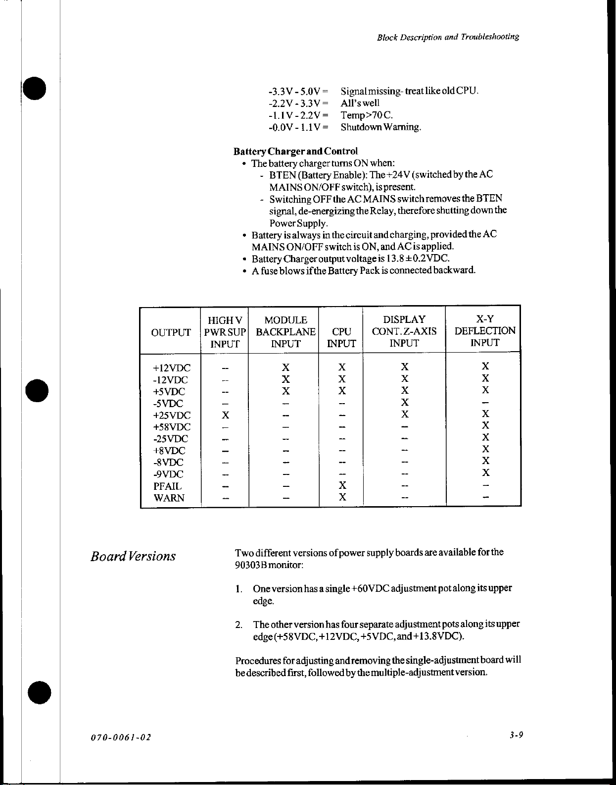
OUTPUT
+12VDC
-12VDC
+5VDC
-5VDC
+25VDC
+58VDC
-25VDC
+8VDC
-8VDC
-9VDC
PFAIL
WARN
Battery
+
*
«
+ A fuse
HIGH
V
PWRSUP|
INPUT
-3.3V-5.0V= | Signalmissing-
-2.2V-3.3V=
-LI1V-22V=
-0.0V - 1.1V=
Charger
The
battery
-
BTEN
MAINS
-
Switching
signal,
Power
Battery
MAINS
Battery
is
always
ON/OFF
Charger
blows
MODULE
BACKPLANE|
INPUT
charger
(Battery
de-energizing
Supply.
All’s
and
Control
turns
ON/OFF
OFF
in
switch
output
ifthe
Battery
INPUT INPUT
well
Temp>70C.
Shutdown
ON
Enable):
switch),
the
AC
MAINS
the
the
circuit
is
ON,
voltageis
Pack
CPU
when:
The+24V
Relay,
CONT.Z-AXIS
treat
like
old
Warning.
(switched
is
present.
switch
removes
therefore
and
charging,
and
AC
13.8+0.2VDC.
is
connected backward.
DISPLAY
is
applied.
på
på
på
pi
pe
I
i
shutting
provided
|
CPU.
by
the
AC
the
BTEN
down
the
AC
X-Y
DEFLECTION
INPUT
IS
EE
EEE
1
the
Two
Board
070-0061-02
Versions
different
90303B
1.
Oneversion
edge.
2.
Theother
edge(+58VDC,
Procedures
be
described
versions
monitor:
has a single
version
for
adjusting
first,
of
power
has
four
+12VDC,
and
followed
+60VDC
separate
+5
removing
by
the
supply
boards
are
available
adjustment
adjustment
VDC,
and+13.8VDC).
the
single-adjustment
multiple-adjustment
pot
pots
along
forthe
its
upper
along
its
board
version.
upper
will
3-9
Page 30
90303B/90311B/90312B
PC
Bedside/Central
Monitor
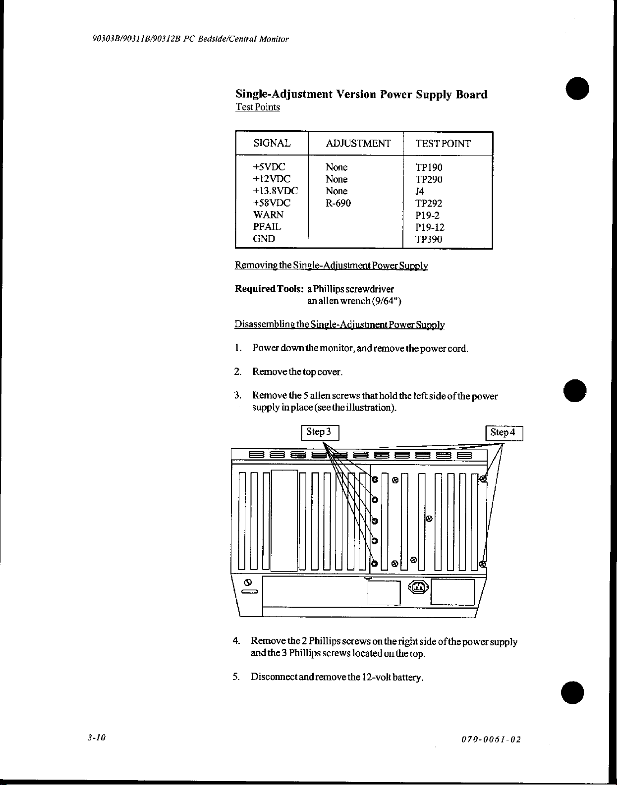
Single-Adjustment
Test
Points
SIGNAL
+5VDC
+12VDC
+13.8VDC
+58VDC
WARN
PFAIL
GND
Removing
Required
Disassembling
1.
2.
the
Tools: a Phillips
Power
down
Removethetop
ADJUSTMENT
None
None
None
Single-Adjustment
an
allen
the
Single-
the
monitor,
cover.
Version
R-690
screwdriver
wrench
Adjustment
and
Power
Power
Supply
(9/64")
Power
remove
Supply
TEST
TP190
TP290
J4
TP292
P19-2
P19-12
TP390
Supply
the
power
Board
POINT
cord.
3.
Remove
supply
===
&
4.
Remove
and
5.
Disconnect
the 5 allen
in
place
the 2 Phillips
the 3 Phillips
and
screws
(see
the
screws
remove
that
hold
the
illustration).
우르르
Пе
lo
lo
b
LL
screws
located
the
e||?
on
the
on
12-volt
battery.
right
the
left
루주
©
side of
top.
side of
©
the
두
the
power
d
4
/
power
supply
3-10
070-0061-02
Page 31

6.
Disconnect
7.
Disconnect
(the
following
J5
P102
bottom
cable)
illustration.
onthe
(the
from
AC
top
the
Block
Input
Assembly
cable),
Power
Description
P12
(the
Supply
and
middle
Board.
Troubleshooting
cable),
and
See
the
P19
Ga
8
Ea
33
O
OE
8.
Removethe
Adjusting
Required
ビー
ㅁ
ㅠ ㅁ ㅠ ㅁ ㅁ ㅁ ㅁ ㅁ O 의
8
o © 6
Cd
the
Tools:
power
Power
Supply
aDVM
an
Alignmenttool
supply
assembly
E
レー『102
이
;
i
so
i
È
ch
P19
ο
ο]
from
the
monitor.
070-0061-02
This
monitor
electricity.
High
voltages
1.
Turnoffmonitor
source.
2.
Remove
CPU
board.
3.
Locate
the
(nextto
the
Power
the
contains
Open
are
present.
power
top
cover
Supply
toroid
transformer).
Note:
circuitry
only
ata
Do
not
approved
and
leave
shell
and
Assembly
that
may
be
damaged
static-approved
wear
jewelry
testprobes.
the
AC
cord
disconnect
and
the
the
Power
by
static
workstation.
or
use
other
connected
12 V battery
to
Supply
board
than
power
on
the
3-11
Page 32
90303B/90311B/90312B
PC
Bedside/Central
Monitor
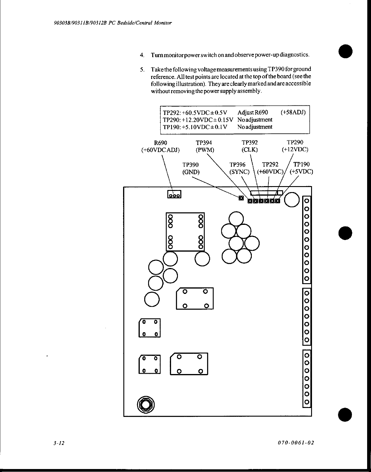
4.
Turnmonitor
5.
Takethe
reference.
following
without
TP292:+60.5VDC+0.5V
TP290:+12.20VDC+0.15V
TP190:+5.10VDC+0.1V
R690
(+60VDC
power
following
All
test
points
illustration).
removing
ADJ)
the
TP394
(PWM)
switch
voltage
measurements
are
They
power
on
and
observe
located
are
clearly
supply
|
power-up
using
TP390
at
the
top
of
the
marked
assembly.
Adjust
Noadjustment
Noadjustment
TP392
(CLK)
and
R690
diagnostics.
for
ground
board
(see
the
are
accessible
(+58ADJ)
TP290
(H2VDC)
ο
TP390
(GND)
ο ο
ο ο
TP396
(SYNC) | (+60VDC)/
NA]
TP292 / TP190
(+5VDC)
|
o
o
3-12
ο
070-0061-02
[OooOoOoooll[ooooooolloooooooooool
Page 33
MNISIVAH
OLA8S+
AX
|
DAY
ease
||
Io
ogra
SdAH
OL
AST+
|
LAAX
A8I+
Pe
4
SINISIVAH
NISIVAH
NINISLVGH
MNISÍVAH
A-X
OLA8Y
AK
OL
AS
K
|
AX
A-X
OL
OL
Ati
AST-
a
BINIS.LV
ATI+
AH
À-X
OL
ACJ+
M
MNISIVAH
(HHTIOHLNOO
A-X
OL
AvTdSI
WOU:)
MOVadada
ONAS
je
|
|
YATI
UVAMONO
INVITIOVA
37000)
—|
ATH
|
|
οι
|
|
zia
;
(σι)
AS+
|
|
e
«vad
|
|
|
AS-
一
NVAOVIQ
auvoa
003
OL
AS+
„va
|
|
;
|
|
À
INITIH
+
Le
bi
«NUVA
|
110
Ha
|
|
|
AS
+NMOGLNHS
—
|
ATT
|
|
_
HOO'IA
|
AIddNS
YIMOd
|
GALVINOMNINN
DAT
LAdNÍ
[A
Li
(or)
|
AOVITOA
HOLIMS
TOHTHS
cr
REN
HOLMS
td
|
o
ο
TINA
.
.
.
OIC
134
一
一
Fi
TAVA
IVEMONO
~
*
ANTA
IIVHd
ASI
p
TIAITNA
AWd
|
INdLNO
xiang
—
[CY
OSTIA
o
ACT
gqoana
.
ーー
9
=.
OVAOPZ
OVAOOT
o
>
=
Le
È
È
E
,
て
AC
Tadns
:
I+
с
S
u
ATOVIdIONI
è
HTAVNH
SaradnS
NMd
+
ANALIVA
|
fav
osra
AS+
AMALIVA
ПЕ
|
|
|
ATI
|
0L64
=
|
|
Ns
131
dAALNAAO
ef
CAL
TADAN
OLAY:
Y
HOLIMS
°
Osh
ION
WALT
NOWWO9
INA
Iv
As
0/64
Ag
EI
于
“YN
no
YOLINOW
dNAL-AHAO
DNINAVA
IS
(A
A8+
F%
AZEI
-
ast
EE
一
NMOGLNHS
ANELIVE
NMOGLOHS
Y
JOaLNOO
ANLAVLS
e
IL
ANA
ae
YADAVHI
xaLiva
OALNOO
DN
OLTA
TIAVNA
LIVE
ζ0:1900-0έ0
©
©
Page 34
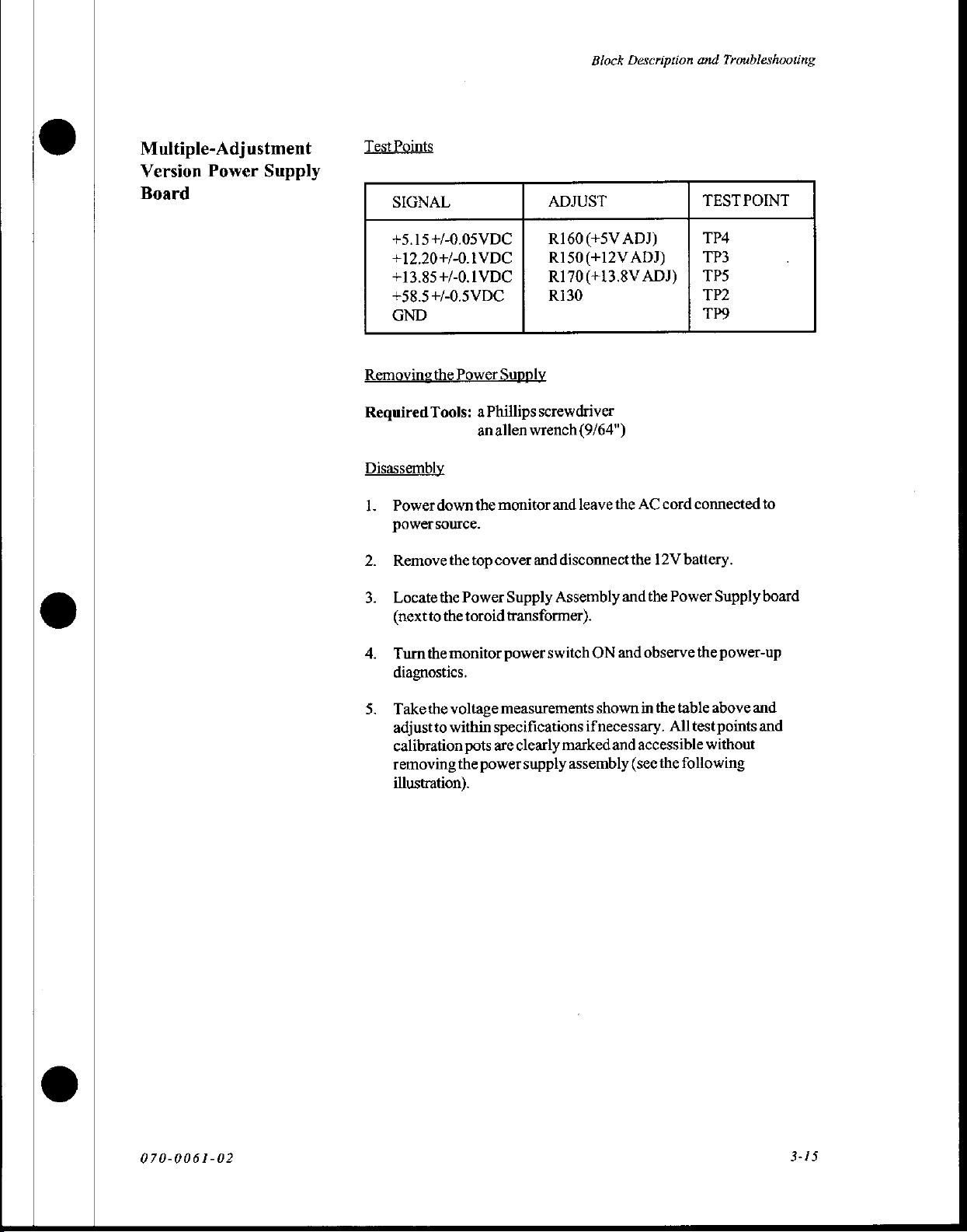
Multiple-Adjustment
Version
Board
Power
Supply
Test
Points
SIGNAL
+5.15+/-0.05VDC
+12.20+/-0.IVDC
+13.85+/-0.1VDC
+58.5+/-0.5VDC
GND
ADJUST
R160(+5V
R150(+12V
R170(+13.8V
R130
Block
Description
ADJ)
ADJ)
ADJ) | TPS
and
Troubleshooting
TEST
TP4
TP3
TP2
TP9
POINT
Removingthe
Required
Disassembly
L
Tools: a Phillips
Power
power
source.
Remove
Locate
(nextto
Turn
the
diagnostics.
Take
the
adjust
to
calibration
removing
illustration).
Power
down
the
the
top
the
Power
the
toroid
monitor
voltage
within
pots
the
Supply
screwdriver
anallen
powersupply
wrench
monitor
cover
power
measurements
specifications
are
and
and
disconnect
Supply
transformer).
Assembly
switch
clearly
marked
(9/64")
leave
the
AC
the
and
ON
and
shown
ifnecessary.
and
accessible
assembly
(see
cord
12V
battery.
the
Power
observe
in
the
table
All
the
following
connected
Supply
the
power-up
above
test
points
without
to
board
and
and
070-0061-02
3-15
Page 35
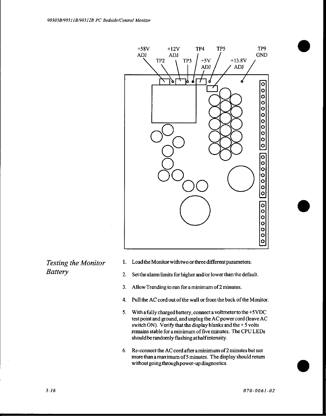
90303B/90311B/90312B
PC
Bedside/Central
Monitor
+58V
ADJ
+12V
ADJ
TP2
AL
dd
TP4
TP3 | +5V
ae
TPS
+13.8V
d
TP9
GND
©
O
O
Ce
CO
©
oo
O
Testing
Battery
3-16
the
Monitor
μα
Load
the
Monitor
Set
the
alarm
limits
Allow
Trending
Pull
the
AC
cord
Witha
fully
charged
test
point
and
ground,
switch
ON).
Verify
remains
should
Re-connect
more
without
stable
for a minimum
be
randomly
the
than a maximum
going
through
with
for
to
run
out
that the
flashing
AC
cord
of
battery,
two
or
three
different
higher and/or
for a minimum
the
wall
or
from
connect a voltmeter
and
unplug
after a minimum
of 5 minutes.
power-up
the
display
of
five
at
half
intensity.
diagnostics.
parameters.
lower
than
of 2 minutes.
the
back
AC
power
blanks
and
minutes.
The
The
of 2 minutes
display
the
default.
of
the
to
the
cord
the + 5
CPU
should
070-0061-02
foo0o0000][0000000][00000000000]
Monitor.
+5
VDC
(leave
AC
volts
LEDs
but
not
retum
ο
Page 36
7.
Verify
etc.)
8.
Ifmemory
that
are
still
allmemory
present
and/or
and
settings
and
settings
have
have
Block
Description
(e.g.,
not
changed.
changed,
and
alarms,
replace
the
Troubleshooting
trends,
classes,
battery.
Replacing
the
Battery
Recommendedreplacementinterval
every 2 to 3 years.
1.
Turnoffpowertothe
2.
Removethebatteryhold-downbracket,
wires.
Replacethe
Re-install
Allow
battery
the
the
new
test.
battery.
battery
Monitor,
bracket
battery
to
and
and
charge
for
the
remove
cover,
for
24
rechargeable
the
and
unplug
and
turn
hours,
cover.
on
then
battery
the
AC
perform
is
battery
power.
a
070-0061-02
Page 37
90303B/90311B/90312B
PC
Bedside/Central
Monitor
Display
Controller
The
refresh
protect
screen
fails.
The
and
DRAM
waveform
information.
To
the
The
be
transceived
controller
the
generating
the
Board
display
display
graphic
pass
display
access
display
display
controller
its
of
circuitry
indefinitely)
controllerreceives
is
divided
storage,
data
RAM
arbitrator
RAM.
controller's
the
function
interruption.
waveform),
trace
length,
Timing
from
and
the
data
action.
dynamic
own
and
if
data,
and
into
and
to
the
display
by
and
couples
The
display).
Control
trace
position,
etc.,
are
sorting
circuitry
stream
contains
its
RAMs,
phosphor
CRT
either
the
CPU
waveform
stores
it
in
two
32K
the
other
controller,
asserting
then
CPU
arequest
controls
the
CPU
access
accesses
For
this
so
that
display
information
horizontal
storedin
to
is
allow
display
included
the
own
voltage
will
and
orto
software
and
on-board
by
16-bit
is
used
for
the
to
the
address
address/data
to
display
to
display
reason,
CPU
functions
such
as
deflection
RAM
to
display
references,
down
shut
prevent
old
or
deflection
bit-mapped
DRAM
sections.
CPU
the
for
Oneis
pixel
intensification
is
granted
RAM
access
multiplexers
bus
RAM
is
RAM
(required
access
continue
data
type
(bit-map
speed,
along
with
remove
controller
control
to
provides
display
the
on
frozen
data
circuitry
alphanumeric
display.
The
used
for
control
arbitrator.
and
data
to
the
display
interleaved
with
for
is
transparent
without
or
start
position,
actual
data.
information
take
the
right
(to
the
of
to
to
Waveform
latched
waveform
then
and
onto
digital-to-analog
summed
amplified.
composite,
waveform
At
display
generator.
deflection
distorts
The
(640
of
information
raster
slow
beam
the
start-up
data
X-out
CRT
wide
proceeds
scan
ONor
quantizing.
amplifier
face
in
on
data
for
the
display
with
It is
after
passing
of
each
bus
to
These
outputs
so
that
is
divided
optional
stored
from
the
CRT,
OFF
and
waveform
trace
sent
display
data
bus
converter
offset
to
the
deflection
through a "vector
trace,
X-sweep
the
X-sweep
are
summed
as
X-out.
it
will
appear
into a map
PC
Mode).
in
RAM
bottom
to
each
bit
sets
intensities.
is
read
(DD),
and
(DAC).
information
from
amplifier
generator"
information
position
Geometry
Each
onthe
top
is
read
DAC,
and
correction
linear
on
of
pixels
pixel
display
in a fast
out of
out
of
display
routed
to
the
The Y analog
the Y position
as a Y-out
to
is
sent
and
sweep
amplified
and
circuitry
the
CRT.
384
high
by
is
represented
controller.
scan
and
left
RAM.
This
RAM,
Y-axis
signal
DAC
smooth
on
the
speed
sent
the
to
ramp
the
pre-
560
wide
by
one
Asdisplay
to
right
in
pulses
the
070-0061-02
is
bit
a
Page 38
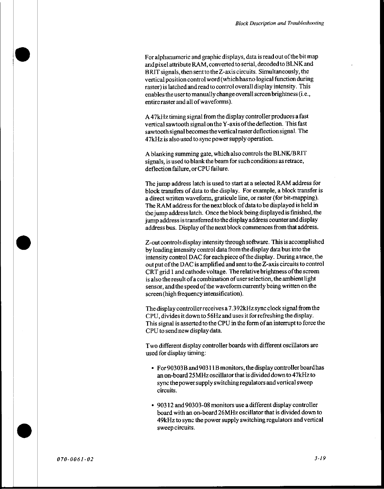
For
alphanumeric
and
pixel
attribute
BRIT
signals,
vertical
raster)
enables
entire
position
is
latched
the
raster
then
user
and
and
graphic
RAM,
sent
control
and
read
to
manually
all
of
waveforms).
displays,
converted
tothe
Z-axis
word
(which
to
control
change
Block
Description
data
is
to
serial,
decoded
circuits.
hasno
overall
overall
Simultaneously,
logical
display
screen
and
read
out
to
function
intensity.
brightness
Troubleshooting
of
the
bit
map
BLNK
and
the
during
This
(i.e.,
A47kHz
vertical
sawtooth
47kHz
A
signals,
deflection
The
block
a
direct
The
the
jump
address
Z-out
by
intensity
out
CRT
is
sensor,
screen
timing
sawtooth
signal
is
also
blanking
is
jump
transfers
written
RAM
jump
address
address
bus.
controls
loading
control
put
of
grid 1 and
also
the
and
(high
signal
signal
becomes
used
to
summing
used
to
blank
failure,
address
address
the
result
or
latch
of
data
waveform,
for
latch.
is
transferred
Display
display
intensity
DAC
DAC
is
cathode
ofa
the
speed
frequency
from
the
display
onthe
Y-axis
of
the
vertical
sync
power
gate,
which
the
beam
CPU
failure.
is
used
to
the
graticule
the
next
Once
to
of
the
next
intensity
control
combination
data
for
each
amplified
voltage.
of
the
waveform
intensification).
raster
supply
also
for
such
to
start
display.
line,
block
of
the
block
the
display
block
through
from
piece
of
and
sent
The
of
user
relative
controller
the
deflection.
deflection
operation.
controls
at a selected
For
data
being
commences
the
currently
the
conditions
example, a block
or
raster
to
be
displayed
displayed
address
software.
display
the
to
selection,
counter
data
display.
the
Z-axis
brightness
being
produces a fast
This
fast
signal.
The
BLNK/BRIT
as
retrace,
RAM
address
transfer
(for
bit-mapping).
is
held
is
finished,
and
display
from
that
address.
This
is
accomplished
bus
into
the
During
the
atrace,
circuits
to
ofthe
ambient
written
on
control
screen
light
the
for
is
in
the
the
070-0061-02
The
display
CPU,
This
signal
CPU
to
Two
different
used
for
¢
For90303B
an
sync
circuits.
»
90312
board
49kHz
sweep
controller
divides
is
asserted
sendnew
display
on-board
the
power
and
with
to
circuits.
it
down
display
display
timing:
and
903 1 1B
25MHz
supply
90303-08
an
on-board
sync
the
receives a 7.392kHz
to
56Hz
and
uses
it
to
the
CPU
in
the
form
data.
controller
oscillator
power
boards
monitors,
switching
monitors
26MHz
supply
with
the
that
is
regulators
use a different
oscillator
switching
sync
clock
for
refreshing
of
an
different
display
divided
and
that
regulators
signal
the
display.
interrupt
controller
down
vertical
display
is
to
oscillators
to
47kHz
controller
divided
and
from
the
force
are
board
to
sweep
down
vertical
the
has
to
3-19
Page 39
90303B/90311B/90312B
PC
Bedside/Central
Monitor
The
Z-out
contrast
different
The
volts
all
this
Logic
beam
adjustment,
steps
blanking
and
the
purposes,
manner.
signals
ON/OFF
signal
is
of
voltage
amplifier
negative
and
brightness
BRIT
and
offset
by
the
brightness
and
then magnified
between - 10
then
drives
voltage
(attributes)
set
of
individual
and
brightness.
the
by
BLNK/
and
CRT
the
by
-80
Z-out
traces,
adjustment,
the
Z-out
scaled
amplifier
volts.
control
grid
amplifier.
etc.,
are
control
cathode
by
the
to
between
Blanking
-100
for
controlledin
and
grid
1
ο
Thehigh
intensity
throughout
included
overall
Grid 4 is
control
dynamic
Ahigh
and+400VDC
power
CRT
prevent
in
Static
frequency
during
in
display
the
and
focus
voltage
supply
protection
phosphor
the
Z-out
protection
intensification
fast
Y-beam
the
whole
trace.
Y-out.
Grid 1 is
intensity,
focus
grid
as
and
dynamically.
correction.
power
supply
and
10kV
for
uses
an
input
circuitry
burning
amplifier
is
is
when
provided
(HFI)
transitions
The
Y-ramp
also
controlled
well
as
brightness
is
adjusted
X-out
is
used
assembly
CRT
anode
voltage
active
during
at
screen
center.
the + 12
VDC
by
spark
to
both
to
is
voltage.
of
+25VDC.
power-up
starts
gaps
circuit
senses
ensure
uniform
signal
for
by
Z-out,
of
individual
by
an
intemal
generate
used
to
provide
Protection
to
decay
on
the
cathode
Y-outtoadd
raster
which
the
first
The
high
and
power-down
is
accomplished
at
intensity
is
not
regulates
traces.
manual
order
-100VDC
voltage
power
down.
and
G1.
©
to
3-20
070-0061-02
Page 40

Block
Description
and
Troubleshooting
X-Y
X-Axis
Y-Axis
Deflection
Boards
Horizontal
mounted
A
transconductance
controller
sensing
the
input
The
outputs
in
controller
Vertical
mounted
staircase
out.
from
required
combined
is
selected
deflection
on
and
resistor.
yoke
and
voltage.
X-crossing
signal
either
the X or
blanks
deflection
on
positions
Aramp
the
display
for
signal
by
(X-axis)
the
inside
of
amplifier
converts
sensing
detector
XCR
the
rear
generator
the
vertical
amultiplexer
it
The
feedback
resistor
senses
to
the
Y axis
direction
the
CRT
(Y-axis)
heat
sink.
from
the
in
controller,
component
of
waveform
takes
the
heat
takes
into
an
path
so
that
when
display
to
prevent
takes
The
display
the
Y-axis,
produces
and
and
fed
place
on
the
sink
on
the
rear
the
X-out
voltage
output
current
provides
output
the
controller.
for
more
phosphor
place
physiological
controller
when
the
ofa
staircase,
to
the
the
current
beam
If
than
on
the
deflection
DACs
controlled
fast
sawtooth
raster
or
deflection.
deflection
of
the
from
through
correct
is
proportional
stops
moving
the
beam
1.4
frames,
damage.
waveforms
are
by
wave
display.
the
fast
Either
sawtooth
board
monitor.
the
display
the
yoke
voltage
board
applied
and
stops
the
and
signal
shape
the
across
moving
display
via
Y-RET
signal
and
to
Y-
When
control
torun,
raster
correction
Text
can
offs
the
RAST
is
low,
unhooked,
amplifier.
The
Y-correction
different
This
corrects
RAST
also
This
circuit
stages
during
during
raster.
The
retrace
driver
and Y output
and
lets
them
becomes
signal
positioning
amplifier,
be
written
bit-mapped
and
Waveforms
vertical
controls
connects
"kicker"
an
open
to
the
rasterramp
Y-out
amplifier
deflection
fornonlinear
switchover
waveform
stage
drop
to
circuit
RAST
is
high,
is
enabled,
resulting
the
raster
is
+25VDC
pulls
ground
in
face
of
scan
generator
allowed
are
then
provides a linear
distances
CRT/deflection
and
display,
the
most
to
+60
during
during
waveform
the
raster
and
both
fast
sawtooth
the
CRT
by
progresses.
is
disabled,
to
go
through
painted
of
VDC
on
from
supply
+8VDC
but
disconnects
positive
during
scan
the
the
operation.
voltages
supply
line
display.
ramp
generator
go
through
Y-axis
turning
When
control
raster
the
Y-correction
face
ofthe
beam
deflection
center
used
to
the Y driver
both
terminal
scan
line
trace.
The
is
the
Y-
raster
deflection.
the
beam
signal
positioning
CRT.
at
of
the
CRT
for
deflection.
and
from
the
of
retrace
intervals
retrace
allowed
on
and
is
screen.
output
Y driver
the
Y
kicker
070-0061-02
3-21
Page 41
90303B/90311B/90312B
PC
Bedside/Central
Monitor
The
feedback
sensing
input
waveform
The
continually
presetrate.
The
clipped
for
and
more
resistor
voltage.
during
vertical
settled
detect
It
output
of
waveforms
clipping
to
cause
than
before
the
1.4
path
provides
so
that
The
damping
scanning.
detector
whether
does
so
the
circuit
(i.e.,
allowing
CRT
frames.
the
correct
output
current
path
provides
is
made
the Y deflection
by
sensing
is
has
to
be
the
used
to
the
deflection
the
blanking
blanked
voltage
through
up
ofa
voltage
ensure
if
the
across
the
them
is
proportional
linearization
pair
of
comparators
is
moving
across
proper
settled
for
the
vertical
faster
the
display
at
the
dotted
deflection
yoke
and
of
the
that
thana
deflection
yoke.
appearance
vertical
line
position
to
begin)
stops
for
ο
to
of
Functional
Review
Horizontal
«
Develops
*
Horizontal
*
Adjustments
-
X-Size
-
X-Position
Vertical
Display
(Y-Axis)
*
Develops
*
Generates
«
Fast
Retrace
*
Vertical
*
Adjustments
-
Y-Size
-
Y-Position
~
RASTER
-
RASTER
-
BottomRaster
-
Gimmick
Controller
*
Sends
request
+
CPU
sends
*
Text/Data
-
StoredinPPixel/Attribute
-
Read
Registers
-
Sent
+and-NORM/BRIGHT
*
Waveform/Data
-
Storedin
-
Written
-
Written
-
Summed
(X-Axis)
X-POWER
Crossing
Deflection
Y-POWER
Raster
(60V
Settled
Size
Position
next
control
out
to
Z-AXIS
to
to
Deflection
drive
Detector
(R96)
(R47)
Drive
Ramps
‘kicker’)
Detector
Linearity
Cap
to
CPU
for
frame
of
during
raster
(Parallel
circuitry
control
waveform
waveform
offset
(position)
and
sent
to
through
(XCR)
through
(enabled
for
(VSTL)
new
data
data
to
RAM
mode
to
Serial)
for
RAM
DAC
X-Y
Deflection
X-yoke
Y-yoke
by
Display
Raster
(R77)
(R46)
(R60)
(R104)
(R135)
(Frame
Display
to
Pixel
Beam
DAC
winding
winding
Controller)
Time
Int)
Controller
Shift
and Attribute
ON
(1)
or
Beam
Board
(Y-out)
OFF
ο
(0),
3-22
070-0061-02
Page 42

Block
Description
and
Troubleshooting
Watchdog
*
CPU
-
Will
4frametimes
«
Deflection
-
Willblank
Horizontal
phosphor
Deflection
+
Supplies
+
Frame
*
X-Ramp
Adjustments
«
DACDe-glitch
«
X-Ramp
«
Intensity
+
Contrast
*
Focus
Test
Points
+
TP20-
(deflection)
*
TP
11-Ground
isolating
+
TP
1-Ground
*
TP
12-
Timers
Hung
Timer
blank
Stall
Timing
SYNC
Time
generation
Size
Ground
CPU
Frame
screenifCPU
(76.2mSec)
screen
(XCR)
to
power
interrupt
to
unblank
problems
to
override
or
Display
to
defeat
Sync
(56Hz)
does
within
240mSec
deflection
supply
(56Hz)
(C50)
(R87)
(R142)
(R143)
(R149)
everything.
CPU
Controller
High
Frequency
not
update
fails,
Pulse
Width
HUNG
problems
Display
if
Vertical
to
avoid
Modulators
Aids
in
watchdog
Intensification
RAM
(VSTL)
buming
isolating
timer.
within
or
CRT
(47.3Hz)
display
Aids
in
Z-Axis
¢
Blanking
+
Intensity
+
Focus
Functions
(Beam
ON/OFF)
070-0061-02
3-23
Page 43

90303B/90311B/90312B
PC
Bedside/Central
Monitor
Removing
Boards
Alignment
S
creen
Deflection
Pattern
1.
Power
panel.
2.
Disconnect
3.
Removethe
4.
Removetheallen
heatsink.
5.
Remove
6.
Remove
7.
Removethe
The
Alignment
Controller
Display
To
obtain
the
Isolation
Patterns
Level
board.
Controller
an
or
2
menu.
down
the
all
cables
Display
the
cable
the
cable
X-Y
Pattern
Ifthis
board.
alignment
Diagnostics
Memory,
A
screen
and
monitor
screws
that
heatsink.
and
from
the
Controller
and
that
connects
connects
screen
exercizes
procedure
pattern
screen
mode
select
display
to
Display
remove
Display
PCBA.
phillips
the
power
cannot
on
obtain
will
appear
the
power
Controller
screws
X-Y
all
be
the
menu
Alignment
that
output
to
the
X-Y
circuits
completed,
CRT,
selection
(see
the
cord
PCBA.
secure
to
the
heatsink.
on
the
Display
replacethe
place
the
#1,
Pattern
next
figure).
from
the
the
X-Y
CRT
yoke.
monitor
Display
fromthe
back
in
ο
1.
Interruptresponse:
2.
Pointer
horizontal
toread.
3.
Waveform
linear.
4.
Waveform
waveform
Tespective
5.
Deflection
from
6.
Clipping
dots
and
is
7.
Vertical
and
sections
address
lines.
DAC
A
small
dynamic
and
alignmentmarks.
settling
the
ramp
indicator:
at
the
bottom
bottom
irregular
ramp
edges
and
settled
(leading
of
the
Verify
bits
and
jump
Each
line
linearity:
amount
square
wave
varies
predicator:
square
of
ranges
wave
handshake:
to
within
Verify
and
that
dotted.
toward
(Speed
with
the
wave
the
presence
function:
is
a
different
Verify
noise
(0.2-0.4
(4
cmand
reach
the
Verify
2
mm
that
the
the
square
of
any
blockage
Verify
clipping)
or
come
of
Verify
length
that
ramp
8
cm):
vertical
that
of
the
break
wave
dot
motion
of
that
the
either
within
the
small
to
slopes
mm)
is
Verify
height
the
vertical
top
horizontal
in
the
ramp
also
touch
sides
touch
2
mm.
vertical
the
presence
make
are
normal.
that
of
line
waveform
has
one
during
test
screen.)
of
the
square
the
line.
of
them
easier
smooth
the
ramp
their
reaches
line.
of
its
top
pattern
wave
dotted
o
15
and
has
3-24
070-0061-02
Page 44

Block
Description
RI
ma
mm
and
Troubleshooting
NS
Lul
Lu] Lul Lu) Lul
Le)
Lal
Lal Lal
Lul
Lui
Lul
Lul
Lal
ee
PE
PP
ma
ra
10.
11.
12.
Bright
dot
dot
and
not a vertical
Z-out
levels:
The
appearance
contrast
High
of
of
Waveform
section
right.
Overshoot:
overall
adjustment
frequency
the
square
the
square
of the
appearance
Pause:
Verify
segment
Verify
that
of
intensity
on
the
intensification
wave
is
blank
wave.
intensify
Adjust
ramp
and
waveform
gimmick
top
and
that
the
bright
(dash).
there
are
seven
levels
is
affected
Z-axis board.
disable:
from
the
bright
blank : Verify
on
the
left
capacitor
bottom.
dot
in
the
separate
by
Verify
that
dot
down
that
there
and a blank
on
X-Y
deflection
square
levels
the
setting
the
falling
to
is a
bright
portion
Lo) Lal Lul
Lul
Lal
Lal
La]
Lul
wave
is
of
intensity.
of
the
edge
the
bottom
on
for
best
a
the
070-0061-02
3.25
Page 45

90303B/90311B/90312B
PC
Bedside/Central Monitor
13.
Raster
appears
intensity
sensor
ofdisplay
Pixel
Intensification
in
the
top
left-hand
contro!
covered
may
to
is
entirely
view
Function:
corner
have
to
be
this
clearly.
atnormal
Verify
of the
alignment
decreased
The
pattern
intensity.
NORMAL
|
MEDE
or
that
the
the
ambient
at
INTENSITY
figure
pattern.
top
right
below
The
light
corner
14.
Intensify
equal
of
item
15.
Waveform
present,
If
waveform
spikes
the
three
16.
Sweep
square
line,
within
line
Display
traces
with
compromise,
17.
X-Position
lines
disable:
intensity.
11.
clamp
smooth
clamp
or
noisy
will
be
Speeds:
wave
trace
that
the
upper
3
mm
of
comes
within
Controller
plus
the
various
has
sweep
ifrequired.
Disable:
a
small
All
tops
Otherwise,
function:
and
not
ragged.
is
not
working,
(several
ata
Verify
the
widths
gap
cm
lower
vertical
that
come
within
two
of
the
left
vertical
4mm
of
simultaneously
of
the
speeds).
Verify
in
the
and
bottoms
tops
will
be
Verify
that
the
Note
that
bottom
peak-to-peak),
location,
the
top
horizontal
3
mm.
of
three
bottom
line
and
that
the
left
vertical
adjusts
raster
and
grid
Readjust
that
center.
the
R87
top
line
of the
square
as
the
as
bright
horizontal
bottom
two
lines
and
the
line,
right-hand
horizontal
the
bottom
line.
R87
the
lengths
patterns
for
the
of
the
bottom
wave
bright
lines
two
are
will
upper
ramp
vertical
lines
horizontal
on
the
ofall
(all
generated
best
overall
must
section
are
dotted.
be
full
line
of
trace,
and
come
of
these
three
be
of
3-26
070-0061-02
Page 46

Block
Description
and
Troubleshooting
Overall
18.
through
steadily
segment
contained
the
right
Display
flashing 3 cm.
flashing
19.
20.
controllers
line
Auto
Brightness:
changes
control
Memory
and
right
is
dramatic
Display
the
blinking
inside
of
when
of
Timing:
box
at
the
line
of
it.
Verify
entirely
the
right
the
wraparound:
three-fourths
steadily
with a 26
line
centered
below
Verify
the
Z-axis
if
wrap
within
two
ambient
board
around
Verify
the
top of
the
segment
flashing
the
lines
anda
that
the
the
box,
line
Note:
MHz
in
the
non-flashing
for
such
that
the
light
sensor
must
Verify
that
of
the
square
is
not
presence
screen.
oscillator
upper
display
be
working.
The
portion
steadily
anda
randomly
exists.
portion
line.
boards.
intensity
is
covered.
properly
the
right
wave
for
Ignore
half
are
ofa
line
partially
box
must
of
the
solid
blinking
set.
segment
flashing
Y1
will
of
the
the
noticeably
The
of
the
as
shown.
have
both
line
is
line
to
have a non-
box,
anda
upper
of
the
contrast
ramp
wave
Distortion
a
21.
22.
Dynamic
same
vertical
are
moving.)
Y.DAC
C50
onthe
range
settling
height
de-glitch
Display
time
test:
as
the
top of
check: Atthis
Controller
Board
Dotted
line
should
the
square
wave.
location, a small
isnot
properly
be
(Dots
pip
will
adjusted
entirely
normally
show
if
at
070-0061-02
3-27
Page 47

90303B/903
11B/90312B
PC
Bedside/Central
Monitor
Display
Required
Prelimin
Equipment
ary
Set-
Alignments
*
Jumper
*
Small
flat-blade
«
Patient
Up
L
Enter
the
holding
power-up
-
LEVEL
[112181415161
wire
screwdriver
simulator
Diagnostics
a
finger
in
each
sequence.
SELECT
1
OPTION
1.
DISPLAY
2.
TOUCH
3.
CHANGE
4.
DIAGNOSTIC
5.
DIAGNOSTIC
6.
DIAGNOSTIC
RESET
7.
8.
BEGIN
MENU.
| |
menu
lower
The
following
BY
PATTERNS
KEY
ANALYSIS
TEST
TEST
TEST
TEST
MONITOR
NORMAL
RS232
ON
(about
6
inches
by
cycling
corner
ofthe
menu
PRESSING
OR
PARAMETERS
(NO
MENU
MENU
MENU
MONITOR
long)
power
screen
will
NUMBER
MEMORY
EXIT)
1
2
3
OPERATION
NORMAL
to
the
monitor
during
be
displayed.
AT
BOTTOM
LOOP
71/8l]
and
the
ONCE
©
2.
Touch
1,
DISPLAY
This
will
display
SELECT
„LEVEL
1121314151681
3.
Touch
deflection
2
MENU
1,
DISPLAY
checks
the
OPTION
1.
DISPLAY
2.
DISPLAY
3.
DISPLAY
4,
DRAM
5.
CMOS
6.
EEROM
7.
RESERVED
8.
RETURN
and
PATTERNS
Level 2 Menu.
GRID
RASTER
ALIGNMENT
DISPLAY
RAM
DISPLAY
TO
..
RS232
GRIDPATTERN,
alignment
OR
BY
PRESSING
PATTERN
PATTERN
DISPLAY
PREVIOUS
ON
procedure.
MEMORY,
NUMBER
PATTERN
MENU
on
the
on
NORMAL
Level
the
Level
AT
BOTTOM
LOOP
7|8|
2
menu
to
|
Menu.
ONCE
start
the
3-28
070-0061-02
Page 48
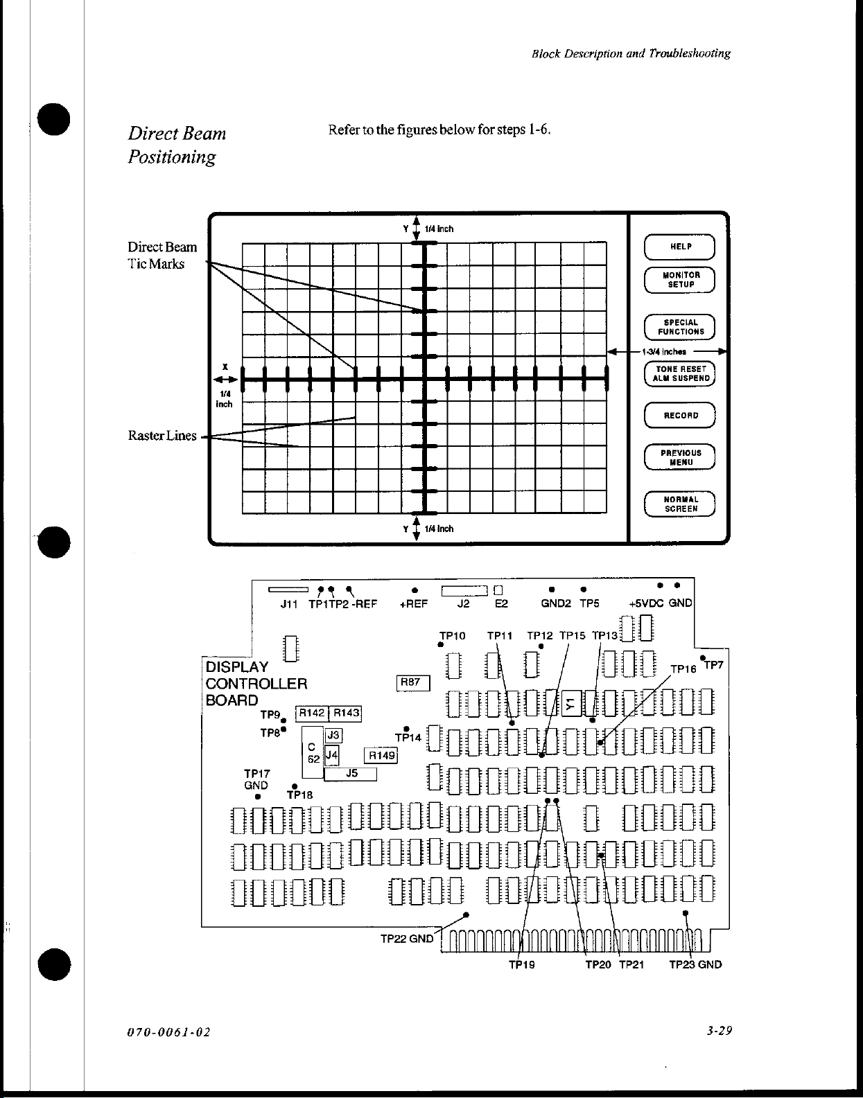
ο
Direct
Positioning
Direct
Tic
Raster
Beam
Beam
Marks
Lines
Refer
to
figures
the
Y 1/4
below
inch
for
steps
Block
1-6.
Description
and
Troubleshooting
HELP
MONITOR
SETUP
SPECIAL
FUNCTIONS
1-3/4
inches
TONE
RESET
ALM
SUSPEND
RECOAD
O
тв
|
Y
==
BOARD
TPg
my.
00000000000000000
0000000000000000000000
000000
©
pr
311
TP1TP2-REF
i
Ea
ыы
8
.
+REF
an
JP10
=U
(0000
LOGO)
0000000090000
GND
0000
TP22
J2
E2
TP11
TP12
Dos
0000
TP19 TP20
. .
GND2
TPS
TP15
misi | i|
di
opa
+
D
40000
..
+5VDC
GND
e
τρις
(m)
Cr
ΤΡ
fn
HELI
0000
ČD
TP21
TP23
GND
070-0061-02
3-29
Page 49
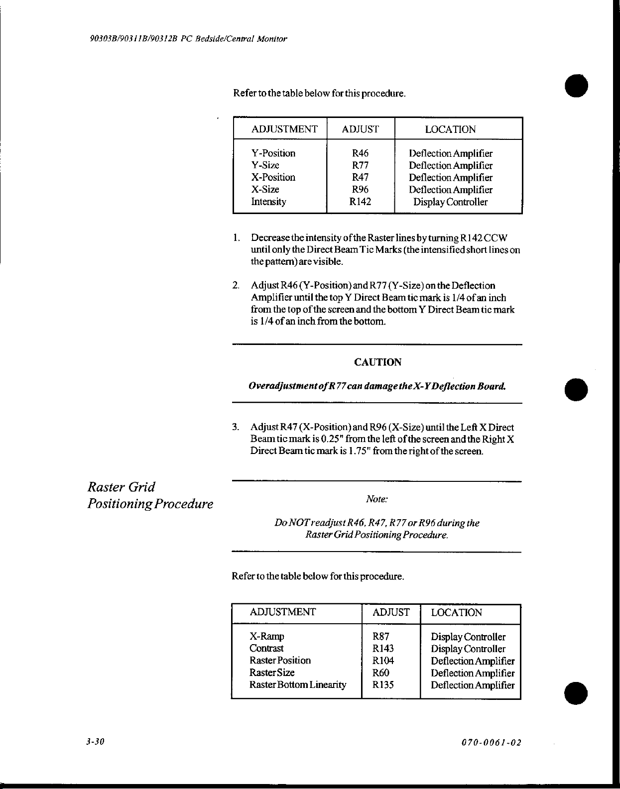
90303B/90311B/90312B
PC
Bedside/Central
Monitor
Refer
to
ADJUSTMENT
Y-Position
Y-Size
X-Position
X-Size
Intensity
1.
Decrease
until
the
2.
Adjust
Amplifier
from
is
the
table
the
only
the
pattern)
R46
until
the
top of
1/4
of
an
below
for
this
ADJUST
intensity
Direct
are
(Y-Position)
inch
of
Beam
visible.
the
top Y Direct
the
screen
from
the
procedure.
R46
R77
R47
R96
R142
the
Raster
Tic
Marks
and
R77
and
the
bottom.
LOCATION
Deflection
Deflection
Deflection
Deflection
Display
lines
by
turning
(the
intensified
(Y-Size)
Beam
bottom Y Direct
tic
mark
on
the
is
Amplifier
Amplifier
Amplifier
Amplifier
Controller
R142
CCW
short
lines
Deflection
1/4
ofan
inch
Beam
tic
ο
on
mark
Raster
Positioning
Grid
Procedure
Overadjustment
3.
AdjustR47(X-Position)
Beam
tic
mark
is
Direct
Beam
tic
Do
NOT
readjust
Raster
Refer
to
the
table
below
ADJUSTMENT
X-Ramp
Contrast
Raster
Position
Raster
Size
Raster
Bottom
Linearity
of
R77
0.25"
mark
for
CAUTION
can
damage
and
from
is
1.75"
Note:
R46,
Grid
Positioning
this
procedure.
R96
the
left
from
R47,
ADJUST
R87
R143
R104
R60
R135
the
X-Y
(X-Size)
the
R77
until
of
the
screen
right
or
R96
Procedure.
Deflection
the
Left X Direct
and
the
of
the
screen.
during
LOCATION
Display
Display
Deflection
Deflection
Deflection
the
Controller
Controller
Board.
Right
X
Amplifier
Amplifier
Amplifier
O
©
3-30
070-0061-02
Page 50
Center
R143
onthe
Display
Block
Description
Controller
board.
and
Troubleshooting
Intensity
Alignment
Procedure
Center
R135
on
the
Deflection
Adjust
R87
(X-Ramp)
Raster
line
overlays
Adjust
R104
Deflection
Beam
Amplifier
Returnto
Continue
Instali a dual-pressure
Connect a pressure
Blood
for a pulmonary
Touch
Touchthe
Amplifier
Tic
Marks.
forthe
normal
onto
Pressure
the
Blank
LABEL
the
(Raster
Position)
Ifnecessary,
Bottom
monitor
the
Intensity
cable
connector
artery
Pressure
SELECT
Amplifier.
on
the
Display
Right X Direct
and
until
the Y raster
readjust
Raster
line.
operations.
Alignment
module
(PA)
into
from a pressure
on
the
module.
line.
softkey.
softkey.
Controller
Beam
R60
(Raster
lines
R135
procedure.
the
monitor.
simulator
Configure
until
Tic.
Size)
overlay
on
the
to
the
Right
onthe
the Y Direct
Deflection
the
top
the
simulator
Touch
the
ART
Touch
the
ZERO
Touchthe
Select
Press
Connect a pressure
10.
Blood
is
configured
Touch
11.
Touch
12.
Touch
13.
Touch
14.
Touch
15.
SCALES
SCALES
the
arrow
Pressure
the
Blank
the
LABEL
the
PA
the
ZERO
the
SCALES
softkey.
softkey.
softkey.
ON.
keys
until
ART
cable
from a pressure
connector
for a pulmonary
Pressure
softkey.
softkey.
on
soft
SELECT
softkey.
SCALE = 180.
the
module.
artery
(PA)
key.
softkey.
simulator
Verify
line.
to
that
the
bottom
the
simulator
070-0061-02
3-31
Page 51
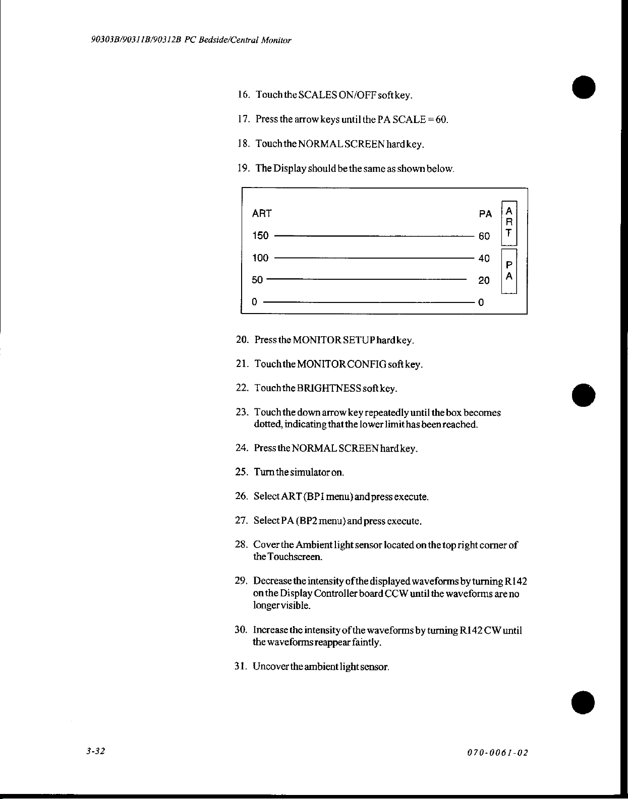
90303B/90311B/90312B
PC
Bedside/Central
16.
Touch
17.
Press
18.
Touchthe
19,
The
Monitor
the
the
Display
SCALES
arrow
NORMAL
should
keys
be
ON/OFF
until
the
SCREEN
the
softkey.
PA
same
hardkey.
as
SCALE = 60.
shown
below.
ART
150
100
50
20.
Press
21.
Touchthe
2.
Touch
23.
Touch
dotted,
24.
Press
25.
Turn
26.
Select
the
the
the
indicating
the
the
ART
MONITOR
MONITOR
BRIGHTNESS
down
arrow
that
NORMAL
simulator
on.
(BP i menu)
SETUP
CONFIG
softkey.
key
the
lower
SCREEN
and
hardkey.
softkey.
repeatedly
hard
press
limit
has
key.
execute.
until
PA
60
40
20
the
box
becomes
beenreached.
=
ココ
PU
27.
Select
PA
(BP2
menu)
and
press
execute.
28.
Cover
the
Ambient
the
Touchscreen.
29.
Decrease
on
longer
30.
Increase
the
31.
Uncover
3-32
the
the
Display
visible.
the
waveforms
the
light
intensity
Controller
intensity
reappear
ambient
of
ofthe
light
sensor
located
the
displayed
board
CCW
waveforms
faintly.
sensor.
on
the
top
waveforms
until
the
waveforms
by
turning
right
corner
by
turning
R142
CW
070-0061-02
of
R142
are
no
until
Page 52
Contrast
Procedure
Adjustment
Refer
to
ADJUSTMENT
Contrast
1.
Ensurethat
2.
Touch
the
table
aminimum
the
pressure
below
for
this
ADJUST
R143
of
softkey
Block
procedure.
two
waveforms
labeled
ART
Description
Display
or
and
LOCATION
Controller
are
displayed.
PA.
Troubleshooting
Focus
Procedure
Bottom
Linearity
Adjustment
Raster
Procedure
Ifnecessary
3.
displayed
Refer
to
ADJUSTMENT
Focus
1.
Touchthe
Adjust
2.
Refer
to
ADJUSTMENT
Raster
the
the
Bottom
table
R149
table
R143
adjust
waveforms.
below
for
pressure
softkey
best
the
for
below
for
Linearity
the
for
this
procedure.
ADJUST
R149
labeled
focus
this
procedure.
contrast
best
PA.
PA
the
of
ADJUST
R135
between
LOCATION
Display
inverse
LOCATION
Deflection
the
Controller
characters.
video
Amplifier
070-0061-02
1.
Pressthe
2.
Pressthe
3.
Touchthe
4.
Touchthe
Adjust
5.
soft
key
R135
box
NORMAL
MONITOR
RECORDER
ALARM
that
so
proportional.
are
SCREEN
SETUP
CONFIG
PARAMS
lettering
the
hardkey.
hardkey.
softkey.
softkey.
the
in
upper
and
lower
part
of
the
3-33
Page 53

90303B/90311B/90312B
PC
Touchscreen
Bedside/Central
The
56
emitter/detector
24
(horizontal)
following
The
Presently,
device
Monitor
infrared
touch
illustration).
original
board
only
numbers
may
screen
pairs.
by
32
the
add
appear
be
consists
The
emitter/detector
(vertical)
set
numbered
had
matrix
48
devices
silkscreened
found
with
of
four
Note:
devices
on
all
48
PCBAs
around
along
are
the
board.
devices
containing a total
pairs
are
arrangedina
the
CRT
face
each
horizontal
installed
even
Some
installed.
of
(see
the
board.
though
all
instruments
Each
emitter
CRT.
every
the
touchscreen
Software
finger
detected
peak
detector
infrared
an
8741/8341
microprocessor
which
output
The
ERTS
80186
carrier
sensor
top
touchscreen
wire
cable.
is
Two X and
1.15msec
generated
which
interrupts
absence
beam.
communicates
and
status).
controller
clock.
The
signal.
(light-dependent
situated
across
one Y emitters
to
produce
is
protected
coordinate
controls
the
infrared
of a carrier
and
comparator
The
infrared
microprocessor
is a Remote
is
SDLC
Thoughit
with
themain
clocked
clock
has
detectors
Universal
no
resistor
board.
It
couples
from
its
are
scanned
by a fuse
(soft
(F1)
keys)
beams
is
processed
to
sense
the
are
located
onthe
Peripheral
CPU
by a 4MHz
is
divided
touchscreen
or
LDR)
to
the
matching
with a 30
pairs.
The
located
are
activated
to
the
by a tuned
presence
controlled
main
through
clock
down
function,
is
physically
display
controller
detector
in
kHz
+5
VDC
supplied
on
the
CPU
by
the
detectors.
amplifier
or
absence
and
monitored
CPU
board.
Interface
three
registers
derived
to
from
produce a 30
the
ambient
mounted
via a two-
front
of
carrier
board.
touchofa
The
anda
of
the
The
(RUPI)
(input,
the
kHz
light
on
the
the
to
by
3-34
070-0061-02
Page 54
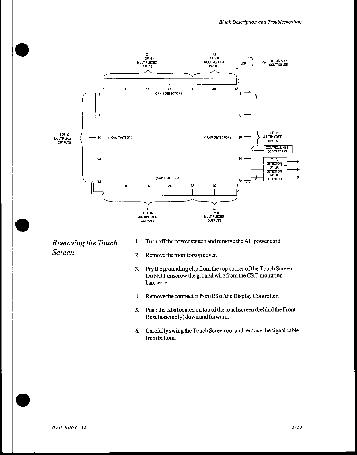
Block
Description
and
Troubleshooting
1
OF
32
MULTIPLEXED
OUTPUTS
Y-AXIS
EMITTERS
8
|
XI
1OF
16
MULTIPLEXED
INPUTS
|
16
X-AXIS
X-AXIS
16
м
10F16
MULTIPLEXED
OUTPUTS
MULTIPLEXED
| | |
24
DETECTORS
EMITTERS
24
e
Y-AXIS
8
MULTIPLEXED
x
10F8
INPUTS
40
DETECTORS:
8
xa
10F8
OUTPUTS
LR
i
>»
1
MULTIPLEXED
INPUTS
CONTROL
De
TO
DISPLAY
CONTROLLER
OF
32
LINES
VOLTAGES:
Removing
Screen
the
Touch
Turn
offthe
power
switch
Removethemonitortop
Pry
the
grounding
Do
NOT
unscrew
hardware.
Remove
Push
Bezel
Carefully
from
the
the tabs
assembly)
bottom.
swing
clip
the
connector
located
down
the
cover.
from
ground
from
on
top
and
Touch
and
remove
the
top
wire
from
E3
of
the
of
the
touchscreen
forward.
Screen
out
the
comer
the
Display
and
AC
power
of
the
Touch
CRT
mounting
Controller.
(behind
remove
the
cord.
Screen.
the
Front
signal
cable
070-0061-02
3-35
Page 55
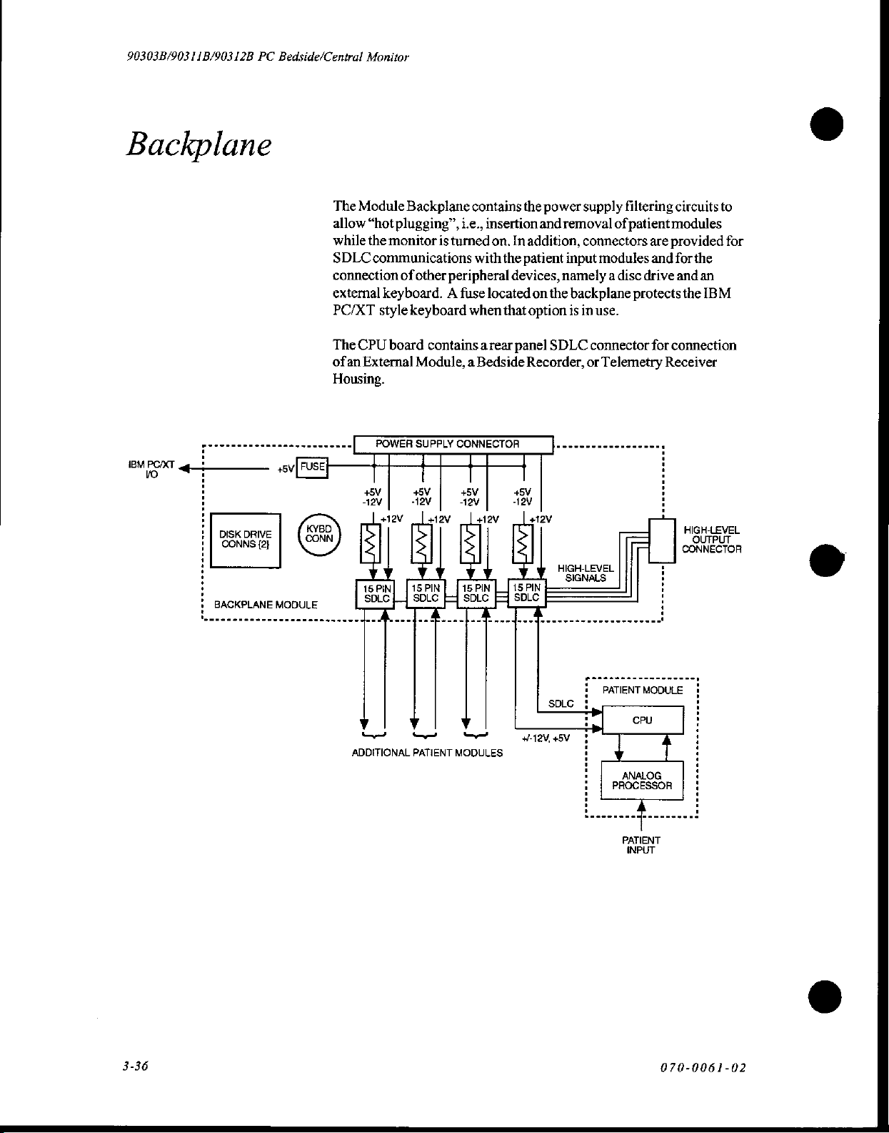
90303B/90311B/90312B
PC
Backplane
DISK
DRIVE
CONNS
{2}
BACKPLANE
Bedside/Central
The
allow
while
SDLC
connection
external
PC/XT
The
ofan
Housing.
MODULE
Monitor
Module
CPU
External
+5V
дам | Sev)
Backplane
“hotplugging”,
the
monitor
communications
of
other
keyboard. A fuse
style
keyboard
board
contains a rear
Module, a Bedside
+5V +5V +5V
Hav
[mov
πρ
se
y
Y
[150W] [isPN]
-De
contains
i.e.,
insertion
is
turned
on.
with
peripheral
located
when
da
ον
He
y
[iso
E
the
power
and
In
addition,
the
patient
devices,
on
that
option
panel
Recorder,
REM
[uz
|
supply
removal
input
namely a disc
the
backplane
is
SDLC
HIGH-LEVEL
SIGNALS
of
connectors
modules
in
use.
connector
or
Telemetry
filtering
patient
circuits
modules
are
provided
and
for
drive
and
protects
for
connection
Receiver
CONNECTOR
τ
:
i
:
:
:
to
for
the
an
the
IBM
HIGH-LEVEL
.
o
3-36
wa
ADDITIONAL
y
PATIENT
ὧν»
MODULES
i
PATIENT
MODULE
i
7
:
i
; :
:
!
; :
2
CPU
y
ANALOG,
|
PROCESSOR | !
PATIENT
INPUT
4
i
:
:
1
:
i
4
070-0061-02
Page 56
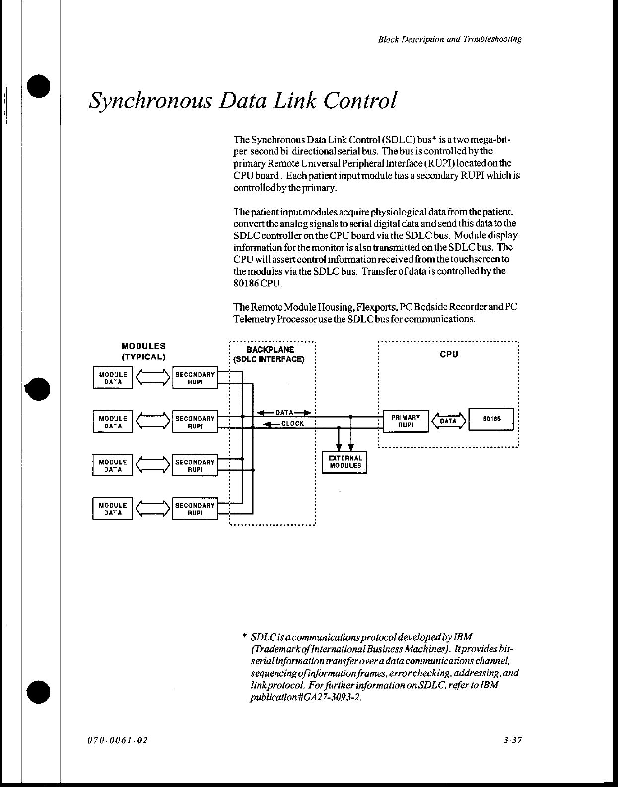
Block
Description
and
Troubleshooting
Synchronous
MODULES
(TYPICAL)
©
MODULE
DATA
こう
SECONDARY
RUPI
Data
The
per-second
primary
CPU
controlledby
The
convert
SDLC
information
CPU
the
80186
The
Telemetry
:
:
(SDLC
[+
0 i :
Link
Synchronous
bi-directional
Remote
board.
patient
the
controller
willassert
modules
CPU.
Remote
BACKPLANE
INTERFACE)
Universal
Each
the
primary.
input
modules
analog
for
the
control
via the
Module
Processor
Control
Data
Link
Control
serial
Peripheral
patient
on
input
acquire
signals
to
serial
the
CPU
board
monitor
SDLC
=:
: :
is
information
bus.
Housing,
use
the
SDLC
(SDLC)
bus.
The
bus
Interface
module
also
Transfer
Flexports,
has a secondary
physiological
digital
via
the
transmitted
received
of
PC
bus
for
:
:
bus*
is
atwo
mega-bit-
is
controlled
(RUPI)
data
data
and
send
SDLC
bus.
on
the
from
the
data
is
controlled
Bedside
communications.
by
located
RUPI
from
the
this
Module
SDLC
touchscreen
Recorder
cru
the
on
whichis
patient,
data
display
bus.
by
and
the
to
the
The
to
the
PC
:
MODULE
mopute
MODULE
DATA
C
|’
C?
SECONDARY
SECONDARY
RUPI
:
+
(—:
: i
ΓΙ
*
DATA
о
SDLCis
acommunications
(Trademark
serial
information
sequencing
linkprotocol.
publication
|
-
Ti
YY
i | EXTERNAL
i
[_wooutes
protocol
of
International
transfer
of
information
For
further
#GA27-3093-2.
over a data
frames,
information
:
=|
PRIMARY
7)
PALMAF
developed
Business
error
Machines).
communications
checking,
on
SDLC,
by
IBM
It
provides
addressing,
refer
80185
ーー
bit-
channel,
and
to
IBM
:
070-0061-02
3-37
Page 57

90303B/903
11B/90312B
PC
Bedside/Central
Monitor
CPU
Board
The
CPU
Board
is
based
with
integrated
counters,
interrupt
The
CPU
*
6banks
*
upto 5 banks
*
upto
*
upto 2 K
*
aninfrared
+
extensive
functions including
memory
and
controller.
board
provides:
of
256K
16 K ofbattery-backed
of
EEROM
touch
I/O
+ 3 SBXmulti-module
+
onemulti-bus
There
are
three
main
sections.
of
CMOS
case
through
the
monitor,
RAM
of
power
ROM
contains a pre-programmed
EEROM
(which
failure
address
and
on a high
I/O
selects,
each
of
256K
and
screen
devices
positions
slot
routes
for
allows
also
contains
or
ON/OFF
data
latches.
integration
two
DMA
wait
state
of
system
each
of
ROM
CMOS
SDLC
controller
data
in
this
permanent
configuration
activation.
16-bit
80186
microprocessor
channels, 3 programmable
generator,
clock
generator
DRAM
on
the
ROM-pack
RAM
controller
system:
ROM,
set
of
instructions
retention
data)
Access
of
to
RAM,
non-volatile
allows
memory
for
data
is
and
the
16-bit
and
the
I/O
operation
data.
retention
obtained
©
in
ο
Dynamic
manipulation.
controller
address
latches
this
The
SDLC
discussion,
bus
currently
allows
controller
with
Housing
The
ofan
RAM
and
or
location
by
ARDC
circuitry
I/O
to
section
controller,
The
through
three
used
interfacing
and
the
patient input
(optional).
CPU
board
External
(DRAM)
It
is
accessed
then
waiting
in
or
detect
contains
and
iSBX*
connectors
by
PC
of
the
multi-bus.
contains
Module,
Receiver Housing.
*
iSBX®
is a protocol
is
used
for
temporary
by
sending
for
data
to
be
RAM.
Data
flow
80186
arbitration. A parity
errors
in
stored
data.
four
parts:
iSBX*
several
miscellaneous
controller
Mode
the
address/data
modules,
allows
with
the
components
bus
The
SDLC
bedside
arear
panel
ability
aFlexport, a Bedside
designed
by
Intel
storage
an
address
sent
or
received
in
or
out
is
generator
controller,
devices
interfacing
to
add
(optional).
through
controller
recorder
SDLC
(optional)
connector
of
data
to
the
address
from
controlled
is
included
multi-bus
listed
in
the
of
the
address/data
future
iSBX*
The multi-bus
two
connectors
allows
data
or
for
Recorder,
awaiting
further
DRAM
the
proper
via
read
and
write
within
controller,
following
control
modules
controller
to
the
display
communication
Remote
Module
connection
or
Telemetry
©
3-38
070-0061-02
Page 58

Other
devices
of
the
I/O
diagnostics,
a
speaker
DUART
keyboard, a modem/DTE
operates
monitor
1.
2.
keyboard
amplifier
to
from
power
RS232
the
infrared
provide
the
lithium
off.
and/or
to
produce
interfacing
The
section
include:
touch
screen
various
for
configurable
battery
in
DUART
Infrared
has
Remote
Block
Description
eight
on-board
controller, a sound
programmed
an
optional
the
two
RS-232C
event
of a power
ports:
Control
IBM
port,
and
Troubleshooting
LEDs
used
generator
alarms, a serial
PC/XT
and a real-time
failure
that
interface
compatible
or
manual
for
includes
clock
that
CPU
80186
Communications
Interrupt
*
+
Synchronous
Ethernet
iSBX
Controller:
Primary
Interrupt-driven
*
Controlled
*
Interfaces
*
Controlledby
MANCHESTER
+
Interfaces
»
Interfaces
control
Data
-
Internal
-
External
-
Bedside
-
Telemetry
-
FlexPort ( all
PCMS/600
-
(Smail
Bus
-
Dual
Serial
-
Parallel
-
Disk
Drive
8259
for
the
architecture
Link
Control
by
the
PRIMARY
monitorto:
Modules
Modules
Printer
the
Interface)
monitor
Port
(via
Processors
models
Interface
the
82586
ENCODER.
monitor
to:
(RS232c)
Card
Controller
monitor
(SDLC)
SDLC
module
housings)
)
(model 90422)
ETHERNET
to
ALL
other
Port
Card
Card
RUPI
CONTROLLER
Networked
and
devices.
070-0061-02
RS232c
Multi-bus
(38)
«
Controlled
¢
Interfaces
-
-
-
*
Interface
by
Dual
monitor
Large Screen
PC
Mode
Terminal
Emulation
to
the
Display
UART
to:
Remote
Controller
(DUART)
Monitor
Mode
board
3-39
Page 59
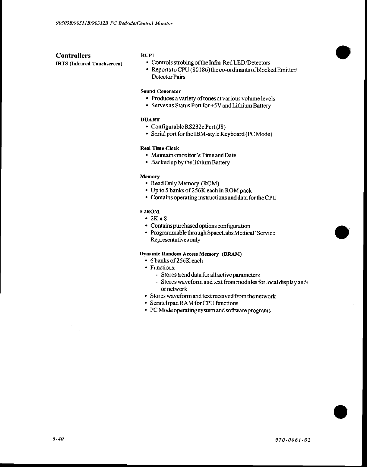
90303B/90311B/90312B
PC
Bedside/Central
Monitor
Controllers
IRTS
(Infrared
Touchscreen)
RUPI
*
Controls
*
Reportsto
Detector
Sound
Generator
+
Producesa
¢
Serves
as
DUART
*
Configurable
*
Serial
port
Real
Time
Clock
*
Maintains
*
Backed
Memory
*
Read
«
Upto5
*
Contains
E2ROM
*
2Kx8
+
Contains
*
Programmable
up
Only
banks
Representatives
strobing
CPU
ofthe
(80186)
Pairs
variety
Status
for
of
Port
RS232c
the
IBM-style
monitor’s
by
the
lithium
Memory
of
256K
operating
purchased
through
only
Infra-Red
the
co-ordinants
tones
at
various
for
+5V
and
Port
(J8)
Keyboard
Time
and
Date
Battery
(ROM)
each
in
ROM
instructions
options
and
configuration
SpaceLabs
LED/Detectors
of
blocked
volume
Lithium
Battery
(PC
Mode)
levels
pack
data
for
the
CPU
Medical
Service
Emitter/
Dynamic
Random
*
6banksof256K
*
Functions:
-
Stores
-
Stores
ornetwork
*
Stores
*
Scratch
*
PC
Mode
Access
trend
waveform
waveform
pad
RAM
operating
Memory
each
data
and
for
system
for
all
and
text
text
received
CPU
(DRAM)
active
parameters
from
modules
from
functions
and
software
for
local
the
network
programs
display
and/
3-40
070-0061-02
Page 60

Block
Description
and
Troubleshooting
CPU
Disassembly
CMOS
»
64K x 16
*
Backed
+
Maintains
-
-
-
-
*
Maintains
-
-
-
-
-
Maintains:
-
Also
-
-
-
1.
Power
panel.
Static
RAM
up
by
the
lithium
network
Node
ID
Nodename
Primary/
Subnetname
local
Central/bedside
600/telemetry
Serial
portassignments
Screen
Remote
Refertomodels,
Maintains
Errorlog
Screen
Recordalarmed
down
configurations
Secondary
configurations
bednames
formatting
access
Installed
formatting
the
monitor
battery
recorder
(Central
(Central
on/off
Options
options,
parameters
configurations
(Central
and
remove
(VBACK)
defaults
only)
only)
only)
the
fora
power
complete
cord
from
listing.
the
back
ESSE
\
Thumbscrew
SE
2.
Removethe
EEE
plug-in
TN
7
mL
interconnect
screw
ROM
pack.
E
©
o
o
o
o||e||?
[|
E
®
へ
=
€
©
Plug-in
ROM
ss
pack
2
5
/
/
070-0061-02
3-4]
Page 61

90303B/90311B/90312B
DCPowerCable | |
PC
Bedside/Central
“TOP
Monitor
3.
Removethe
4.
Disconnectall
Temoveit.
5.
Removethe
+12V
Battery | |
VIEW
12-voltbattery.
cables
from
the
SDLC
cable.
SDLC
Cable | |
\
\
Display
Backplane
Controller
board,
Board
\
\
Ш
|
and
|
Fuse]
[
|
ο
Speaker
connection
Display
Board
Deflection
Board
Cable
и
Controller
Amplifier
H
=
HV
|
HV
6.
7.
8
9.
—]
+
POSN
ADA
XSIZE Y SIZE
ADA
Power
Power
Supply
RemovetheDCpowercable.
Remove
Remove
Ifpresent,
with
the
the
the
heatsink
|
Touch
Speaker
remove
X
POSI Y POSN
Power
Board
Screen
cable.
the
screw
(see
the
OM
때
VALE
Supply | |
cable.
that
interconnects
previous
Ic
πο
ο
yiri
Toroidal
Transformer
the
CPU
illustration).
ET
|
11
drawer
ο
10.
Loosen,
back
11.
Slide
3-42
but
panel
out
the
do
LED
CPU
not
remove,
viewing
drawer
the
thumb
slot
(see
the
assembly
screw
previous
from
the
located
rear
above
the
illustration).
of
the
monitor.
070-0061-02
Page 62

Block
Description
and
Troubleshooting
Replacing
Lithium
Batteries
CMOS
CMOS
1.
2.
batteries
Turn
Remove
Within
and
Re-install
Turn
Reconfigure
off
power
the
20
seconds,
install
the
the
on
AC
should
to
CPU
Drawer/CPU
new
CPU
power.
the
monitor
be
replaced
the
Monitor.
remove
battery.
Drawer/CPU
the
viathe
every 2 to 3 years.
Assembly.
old
lithium
Assembly
BIOMED
battery
and
the
menu
from
Monitor
and
SYS-GEN.
its
holder,
cover.
070-0061-02
3-43
Page 63

90303B/90311B/90312B
PC
Bedside/Central
Monitor
3-44
070-0061-02
Page 64
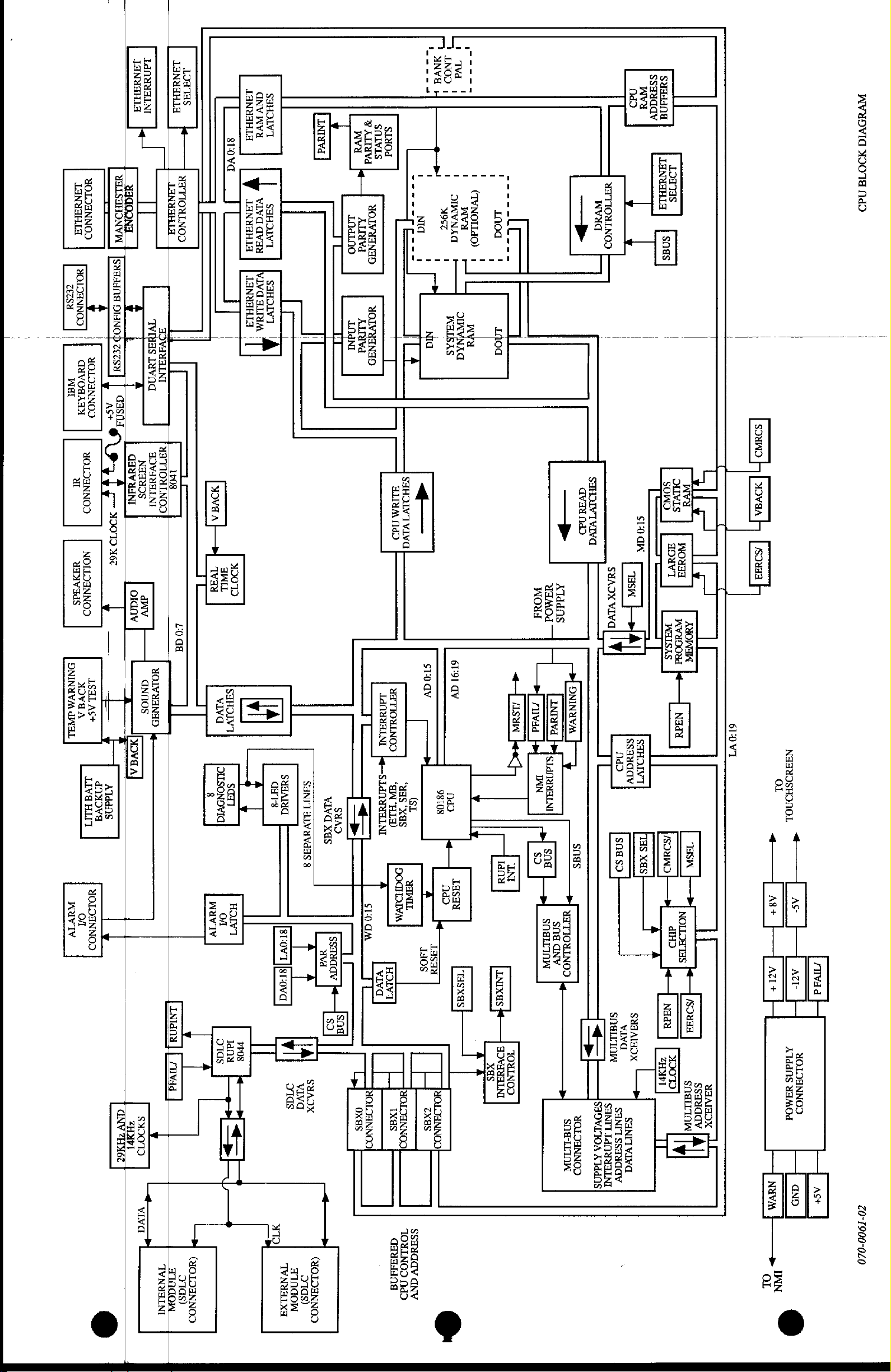
TI
TANSSHIA
sa
||
WEI
DNINHVA
dBL
Wavy
"raNwaHr
|
Porn
|
NHVOBAHY
YOLDANNOD
NOLLOANNOO
AHLSIHONVW
HOONH
IH
[saaaan
Y
Y
;
t
DIAN
E
|
cesa]
HOLIANNOD
|
1
GHSNA
“SL
OF,
QBdvddNI
go
ONE
olanv
ISALAS+
SOVA
|
A
NOVE
Klaas
|
A
LIVE
40228
HUT
YOLDANNOI
ax
νηπᾶος
dv
GNNOS
71139
18700
ADVANALNÍ
AOIVYANAD
で
NV
2HY6
DOT
82072
Y
B
viva
»
FOVANALNI
YITIOLINOI
LANYAHLA
LOTUS
м
|
WATIOWLNOD
ana
i
,
|
108
it
TT
00
:
08
21003
|
|
/uvad
Î
(OLO
TYNYALNI
81000
DTGS)
ヨ
NNOO
ns
ανν
SIHOLVT
Ανα
viva
SAHOLV1
AVAN
|
viva
SaHOIVT
ari
|
|
©
η
TT
LNALNO
10000
я
SAIVIS
SIMOd
хичча
Wva
[|
HOLVHINTO
Alva
YOLVYANAD
AITaVd
1
|
ㅣ
!
1
し
ーーーー
NI
エエ
ーーー
a
'
Nia
IT
4
JANHAHIA
81000
|
|
|
|
LANUAHLA
|
|
LANNAHIA
1
[
|
JovaA
>
8
32072
Tvaa
FIL
SHOTVT
VIVO
OLISONOVIA
9097
|
Wavy
HOIVI
01
2708
lana
<>
ντος
—
SAHARA
αμ
τε
[sr:ov1]
BTOVQ
Sas
am]
NDA
TINGON
SANIT
vivd
SAD
ALVUVAAS
Xas
8
ssaaaqv
7
ava
*--
snal
은
SHAJX
HAD
(4OLDANNOD
Sas)
TU
«€—
>
soda
:
LI
TI
Lp
OLOBNNOO|
οχι
5
SHHOIVI
1
ALTAM
N49
VIVA
91:0
HATIOHLNOD
TanaINI
lm-sranddHLNT
*
HLA)
不
НЕТ
viva
ау
“YAŞ
(SL
“KAŞ
DOCHDIVM.
HALL
x
140$
ГУ
||
[HALIANNOOD
"IOHLNO)
ssaudav
ανν
do
zxgs
txas
TANA4ANA
C
'
1
ーーーーー
NOD
NVA
Tvd
1
|
M
1
ума
I
i
|
SS
6191
AV
98108
nad
Ts
HOLOBNNO
1
1
!
CIVNOLLAO)
Va
1
m
!
OI
M
a
-
LASCI
TaSxas
XdS
A
!
-
Noa
LC
Lo.
1
]
100
|
woud
7Ivdd
SAW
je
TAN
[uuxask—
BOVINALNI
TOULNOD
wvud
>
SgHoryTvryq
—
>
HAMOd
AlddflS
Dunya
|
SLANARELENI
HITIONINOO
SNAHA
snadNy
ーー
>
SFOVITOA
okaNNo
SngrtFInW
ATddNS
う
NdI
|
YATIOULNOD
1
|
|
|
SUD
GW
STAOX
TASA
VIVO[
|>
1
I
SRO")
ο
TT
σα
pax’
(eo
me
SdHAIHOX
L
|
SANTI
ee
LANANELINI
ssauddv
SANG
IANYJHLA
LOHNAS
snas
|
|
|
1
OLIVIS
SONO
一
A
一
一
aan
一
rr
一
一
WHISAS
Wvu00wd
一
|
Kt}
Nadu
κοπο]
pH
TP
le
nada
НУР
TT
Wa
NO
O
NOLLOTTAS
SS
SNHILION
!
|
T
4
ェ
ー
=
Wa
“ESA
[+
e
¡SOME
SALAD
ἨΠΛΙΠΟΧ
rå
|
| |
て
]
て
6L0VT
|
|
SOUND
卢
|
3DvaA
SONA
OL
«
Ag+
ar
H
NEVA
»
TON
ruvad
AS+
|
|
|
ΝΗΞΑΟΞΗΟΠΟΙ,
a
T
AS
As-
|
AT
-
|
XIddNS
SOLOHNNOO
JAMOd
GND
NVHODVIG
32078
1102
]
|
Z0-1900-020
©
o
Page 65

Block
Description
and
Troubleshooting
Troubleshooting
Al
CPUBoard
A2
DisplayController
АЗ
X-YDeflection
A4
EthemetInterface
AS
Power
Аб = Module
Step
1.0
1.1
Condition
Blank
display
Remove
for
a)
b)
c)
d)
monitor
30
seconds.
LEDs
blink Step
LEDs
steady
LEDs
flash
LEDs
off
cover
randomly
and
Procedures
These
Supply
Backplane
view
troubleshooting
Board
Board
Board
Board
Board
status
LED
on
CPU
steps
board
use
A7
A8
A9
A10
All
the
following
Touchscreen
ROMpack
AC
Miscellaneous
High
Voltage
ACSwitchBoard
нок,
goto..
1.4
Step
1.4
Step
1.6
Step
1.6
board
Assembly
Power
references:
board
Supply
If
not
OK,
goto...
Step
1.1b
Step
1.1c
Step
1.1d
Board
1.2
1.3
Normal
athalfintensity.
Measure
controllermarked+5V.
Measure
Power
a)
+58
b)
+25
c)
+18
d)
+12
e)
+8
f)
+5
g)
-5
h)
-8
i)
-12
j)
-25
+5VDC
the
Supply
VDC
VDC
VDC
VDC
VDC
at P102,
VDC
VDC
VDC
VDC
at P102,
VDC
LED
display
Error
at
following
board
at
TP2
at
PIO2,
at
C330
at
TP3
at
TP4
at
P102,
at
P102,
at
P102,
top
pin4
pin
after
LED
Be
right
For
voltages
(A5):
pin
(+)
pin
16
12
pin
17
pin9
power-up
display
sure
the
(component
ground,
onthe
10
Note:
diagnostics
shows
blinking
ROM
pack
side) of
use
TP
GND
complete
or
steady
is
fully
seated.
display
shows
state
Step
Step
Step
Step
Step
Step
1.3f
Step
Step
Step
Step
1.3j
Step
random
code
1.3
1.3b
1.3c
1.3d
1.3e
1.3g
1.3h
1.3i
1.3k
flashing
at
full
intensity.
Adjust
R160
for
+5.15
VDC
TP4.
Ifcannot
adjust,
replace
Replace
"
"
"
"
"
"
"
"
"
AS,
0n
A9
AS
at
AS.
070-0061-02
3-47
Page 66
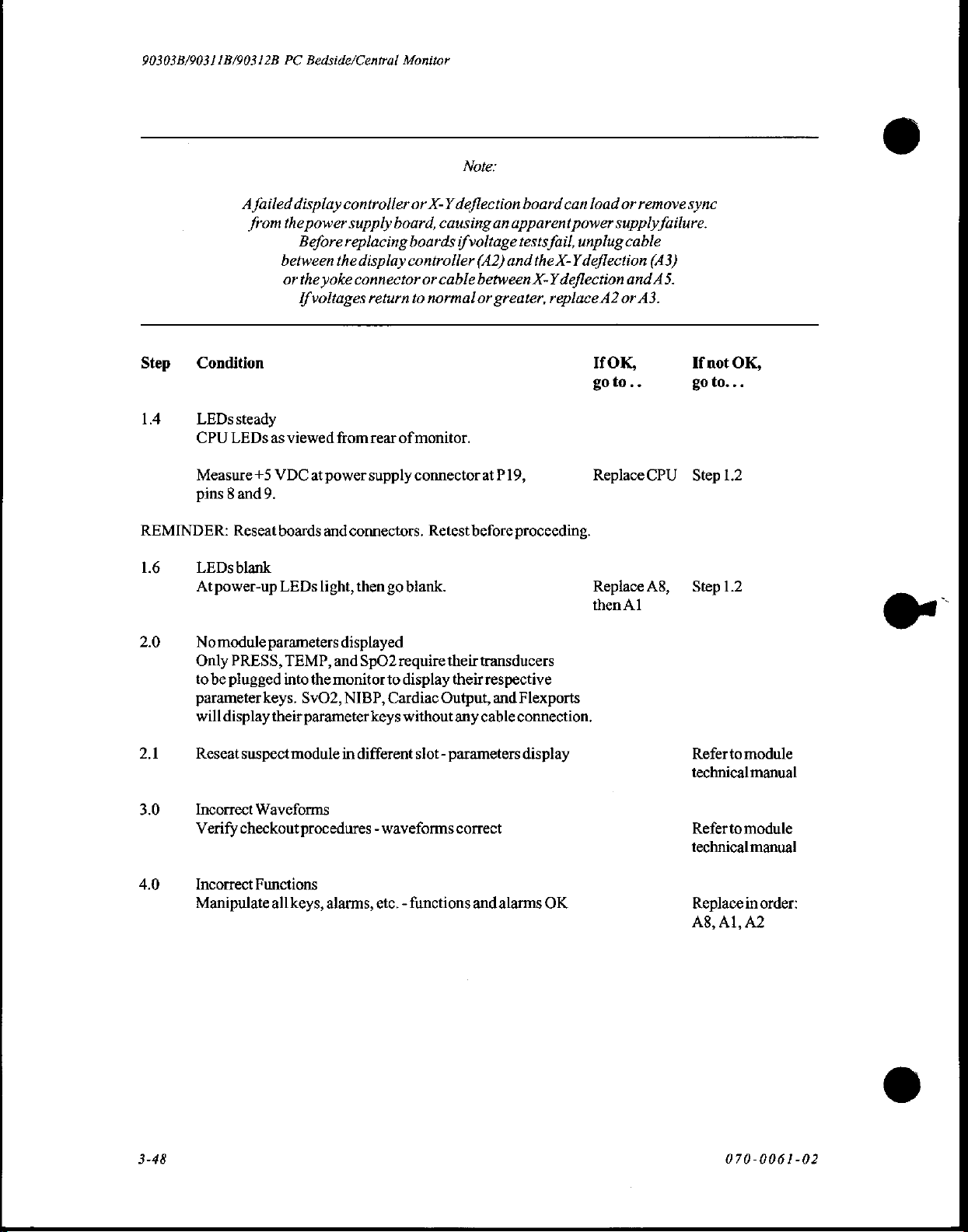
90303B/90311B/90312B
A
failed
from
PC
Bedside/Central
display
the
between
or
power
Before
the
the
yoke
controller
supply
replacing
Ifvoltages
Monitor
or
board,
boards
display
connector
controller
return
or
to
Note:
X-Y
deflection
causing
if
voltage
cable
normal
board
an
apparent
tests
fail,
(A2)
and
the
X-Y
between.X-Y
or
greater,
deflection
replace
can
load
power
supply
unplug
deflection
A2
or
remove
cable
(A3)
and
or
A3.
sync
failure.
AS.
Condition
LEDs
CPU
Measure
pins 8 and
REMINDER:
1.6
LEDs
Atpower-up
Nomodule
Only
to
parameterkeys.
will
Reseat
Incorrect
Verify
steady
LEDs
Reseat
blank
PRESS,
be
plugged
display
suspect
checkout
as
+5
viewed
VDC
at
power
from
9.
boards
and
connectors.
LEDs
light,
parameters
TEMP,
into
their
module
displayed
and
the
monitor
SvO2,
NIBP,
parameter
in
Waveforms
procedures - waveforms
rear
of
monitor.
supply
connector
then
go
blank.
SpO2
require
to
display their
Cardiac
keys
without
different
slot - parameters
Retest
their
Output,
any
correct
at
P19,
before
proceeding.
transducers
respective
and
Flexports
cable
connection.
display
IfOK,
goto..
ReplaceCPU
ReplaceA8,
then
Al
If
not
OK,
goto...
Step
1.2
Refertomodule
technical
Referto
manual
module
technicalmanual
Incorrect
Manipulate
Functions
allkeys,
alarms,
etc. - functions
and
alarms
OK.
Replace
A8,
Al,
070-0061-02
in
order:
A2
Page 67
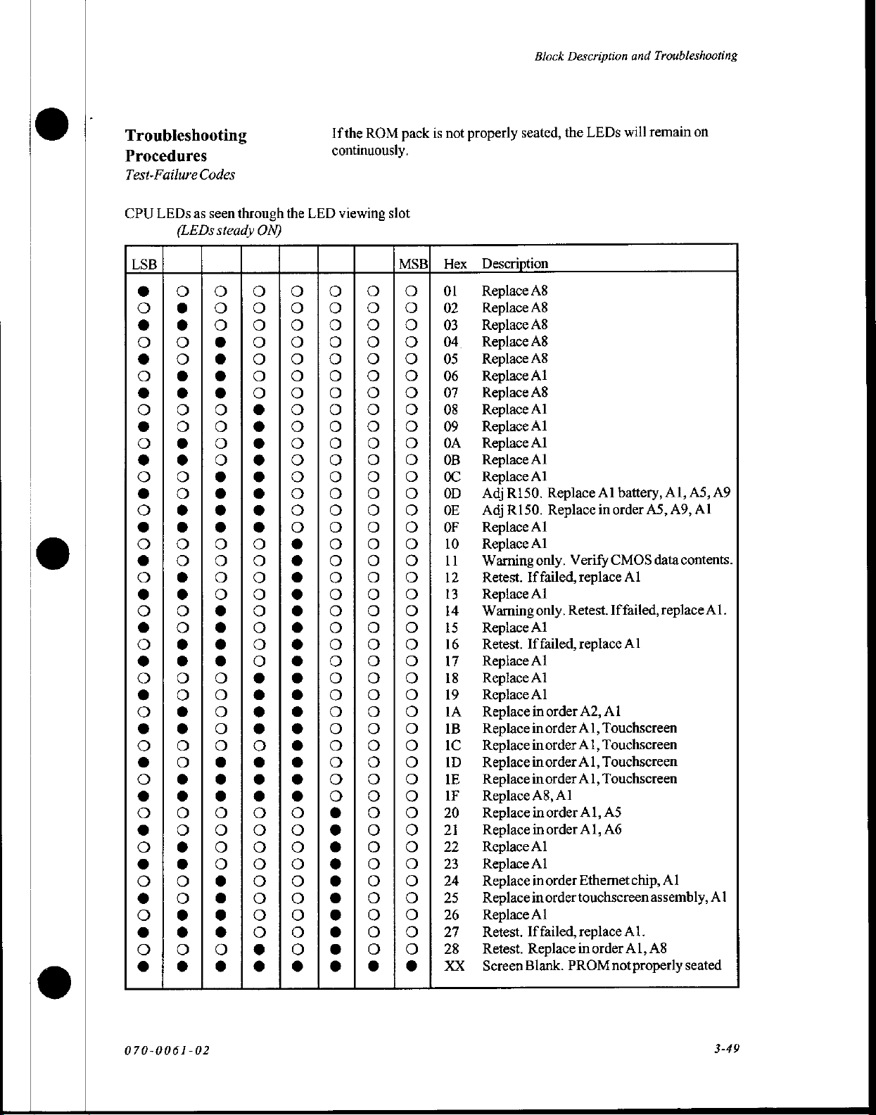
Block
Description
and
Troubleshooting
Troubleshooting
Procedures
Test-Failure
CPU
LEDs
LSB
00000000004006006060606000000060006006006000600606
Codes
as
seen
through
(LEDs
steady
€00000000000000000000000000000000000000000
000000000000000C00000000000000000000000000
the
ON)
00000000000000000000000000000000000000000
If
continuously.
LED
viewing
0000000000000000000000000000000
0600000006068
00000000000000000000000000000000000000000
slot
Hex
01
02
03
04
05
06
07
08
09
0A
08
0C
0D
0E
0F
10
11
12
13
14
15
16
17
18
19
1A
1B
IC
ID
IE
IF
20
21
22
23
24
25
26
27
28
XX
Description
Replace
Replace
Replace
Replace
Replace
Replace
Replace
Replace
Replace
Replace
Replace
Replace
Adj
Adj
Replace
Replace
Warning
Retest.
Replace
Warning
Replace
Retest.
Replace
Replace
Replace
Replace
Replace
Replace
Replace
Replace
Replace
Replace
Replace
Replace
Replace
Replace
Replace
Replace
Retest.
Retest.
Screen
MSB
20000000000000000000000000000000000000000
90000000000000000000000000000000000000000
properly
not
is
pack
ROM
the
seated,
A8
A8
A8
A8
A8
Al
A8
Al
Al
Al
Al
Al
R150.
R150.
Al
Al
only.
Iffailed,
Al
only.
Al
If
failed,
Al
Al
Al
in
in
order
inorder
in
order
inorder
A8,
in
in
Al
Al
in
order
in
order
Al
If
failed,
Replace
Blank.
LEDs
the
Replace
Replace
Verify
replace
Retest.
replace
order
A2,
Al,
Al,
Al,
A1,
Al
order
Al,
order
A1,
Ethernet
touchscreen
replace
inorder
PROM
remain
will
Al
battery,
in
order
CMOS
Iffailed,
Al
Touchscreen
Touchscreen
Touchscreen
Touchscreen
AS
A6
not
AS, A9,
data
Al
Al
chip,
assembly,
Al.
Al,
A8
properly
Al,
replace
Al
on
AS,
A9
Al
contents.
Al.
Al
seated
070-0061-02
3-49
Page 68
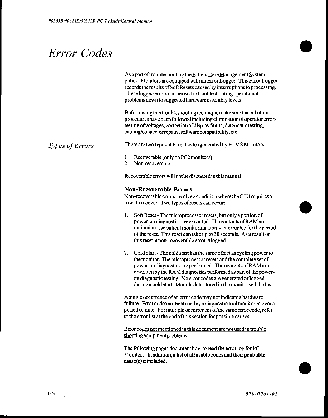
90303B/90311B/90312B
PC
Bedside/Central Monitor
Error
Types
of
Errors
Codes
Asapart
patient
records
These
problems
Beforeusing
procedures
testing
cabling/connector
There
1..
2.
Recoverable
of
troubleshooting
Monitors
the
logged
are
results
of
errors
down
to
suggested
this
troubleshooting
have been
of
voltages,
correction
repairs,
are
two
types
Recoverable
Non-recoverable
(only
errors
will
Non-Recoverable
Non-recoverable
reset
to
recover.
errors
Two
the
Patient
equipped
Soft
can
Resets
be
used
with
caused
in
troubleshooting
hardware
technique
followed
including
of
display
software
of
Error
Codes
on
PC2
monitors)
not
be
discussed
Errors
involve a condition
types
of
resets
Care
Management
an
Error
Logger.
by
interruptions
operational
assembly
make
levels.
sure
elimination
faults,
diagnostic
compatibility,
generated
in
can
occur:
by
this
where
etc..
PCMS
manual.
the
System
This
Error
to
processing.
that
all
of
operator
testing,
Monitors:
CPU
requires
Logger
other
errors,
a
©
1.
Soft
Reset - The
power-on
maintained,
of the
reset.
this
reset,
2.
Cold
Start - The
themonitor.
power-on
rewritten
on
diagnostic
during a cold
A
single
occurrence
failure.
period
to
Error
shooting
The
Monitors.
cause(s)is
Error
of
time.
the
error
codes
equipment
following
included.
In
microprocessor
diagnostics
so
patient
This
reset
anon-recoverable
cold
The
microprocessor
diagnostics
by
the
RAM
testing.
start.
Module
of an
codes
are
best
For
multiple
list
at
the
end
of
not
mentioned
problems
pages
document
addition, a list
are
executed.
monitoring
can
take
error
start
has
the
are
performed.
diagnostics
No
error
codes
data
error
code
used
as a diagnostic
occurrences
this
section
in
this
document
how
of
all
usable
resets,
The
is
only
up
to
30
is
logged.
same
resets
The
performed
are
stored
may
not
of
for
possible
to
read
codes
but
only a portion
contents
interrupted
seconds.
effect
and
contents
generated
in
the
of
As a result
as
cycling
the
complete
as
part
monitor
RAM
for
of
RAM
of
the
or
logged
will
the
power
indicate a hardware
tool
monitored
the
same
error
code,
causes.
are
not
used
in
trouble
the
error
log
for
PC1
and
their
probable
of
are
period
of
set
of
are
power-
be
lost.
over
refer
to
a
8
3-50
070-0061-02
Page 69
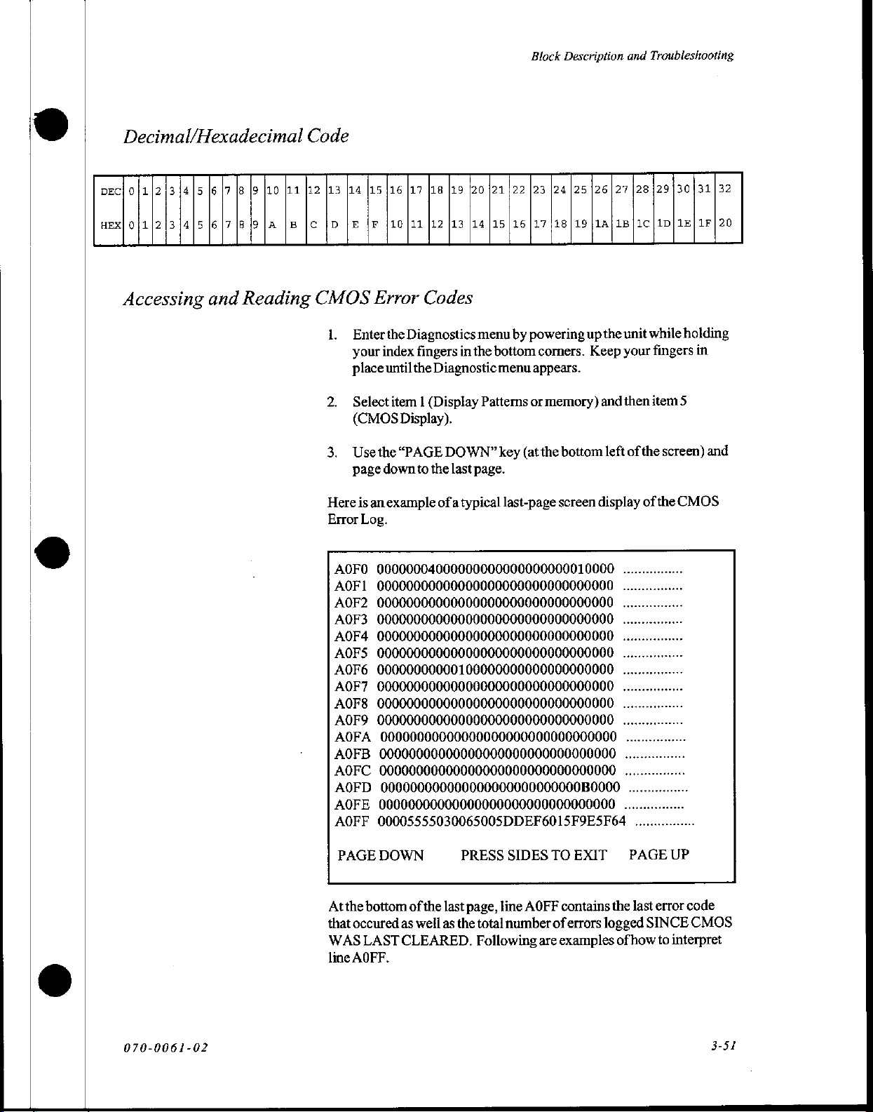
Block
Description
and
Troubleshooting
Decimal/Hexadecimal
DECÍ
0|1|2|314|5
HEX|
0|1|21|3|4|5
Accessing
[6
|7
|6|7
and
Code
|8
lo
[10
[11
[12
(B 9 |A
Reading
|B
|C [D je
[13
[14
CMOS
1..
2.
3.
Here
Error
[15/16
lp
(10/11
Error
Enterthe
your
index
place
until
Select
item 1 (Display
(CMOS
Usethe
page
is
an
Log.
Display).
“PAGE
down
example
|17
[18
[19
[20/21/22
12
13
|14[15|16|1718|19;1A/1B|1C|1D|1E|1F|20
Codes
Diagnostics
fingers
the
to
in
Diagnostic
DOWN”
the
last
ofa
typical
menu
the
bottom
menu
Patterns
key
page.
last-page
123
by
powering
corners.
appears.
or
memory)
(at
the
|24
125
upthe
bottom
screen
126127
unit
Keep
your
and
then item
left
display
of
128129130131132
while
holding
fingers
the
of
5
screen)
the
CMOS
in
and
AOFO
00000004000000000000000000010000
AOF1
00000000000000000000000000000000
AOF2
00000000000000000000000000000000
AOF3
00000000000000000000000000000000
AOF4
00000000000000000000000000000000
AOFS
00000000000000000000000000000000
AOF6
00000000000100000000000000000000
AOF7
00000000000000000000000000000000
AOF8
00000000000000000000000000000000
AOF9
00000000000000000000000000000000
AOFA
AOFB
AOFC
AOFD
AOFE
AOFF
PAGE
Atthe
that
WAS
line
00000000000000000000000000000000
00000000000000000000000000000000
00000000000000000000000000000000
000000000000000000000000000B0000
00000000000000000000000000000000
00005555030065005DDEF6015F9ESF64
DOWN
bottom
occured
AOFF.
LAST
as
CLEARED.
of
the
well
PRESS
last
page,
as
the total
Following
SIDES
line
AOFF
number
TO
contains
of
errors
are
examples
EXIT
................
..
..
..
..
..
..
.
..
..
.
ne
................
PAGE
UP
the
last
error
code
logged
of
SINCE
how
CMOS
to
interpret
070-0061-02
3-51
Page 70
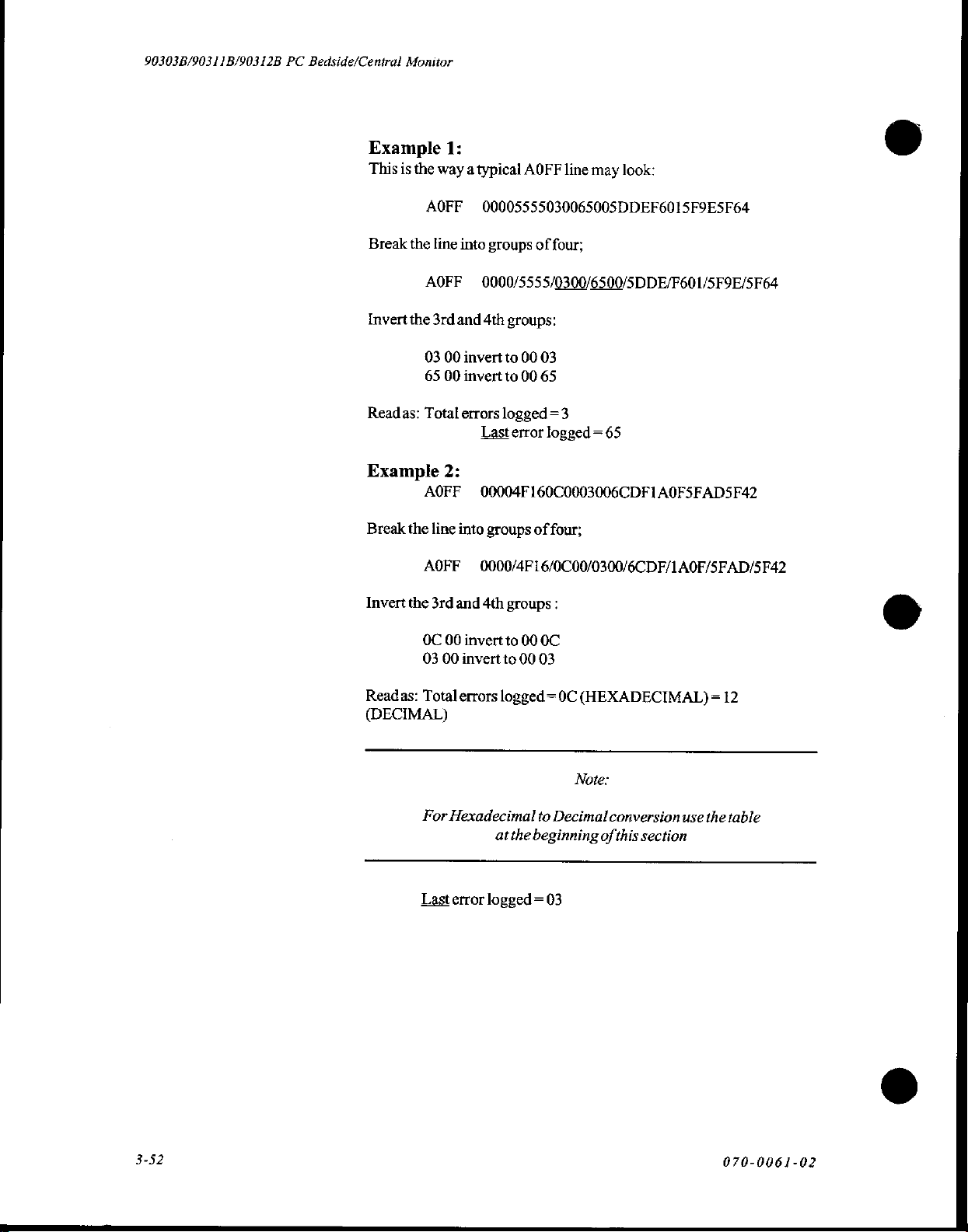
90303B/90311B/90312B
PC
Bedside/Central
Monitor
Example
This
is
the
Break
the
Invert
the
Readas:
Example
Break
the
1:
way a typical
AOFF
line
AOFF
3rd
03
65
Total
00005555030065005DDEF6015F9E5F64
into
groups
0000/5555/0300/6500/5DDE/F601/5F9E/5F64
and
4th
00
invert
00
invert
errors
Last
2:
AOFF
line
AOFF
00004F160C0003006CDF1A0FSFADSF42
into
groups
0000/4F16/0C00/0300/6CDF/1AO0F/SFAD/5F42
AOFF
of
groups:
to
00
03
to
00
65
logged
error
of
line
may
four;
=3
logged = 65
four;
©
look:
Invert
the
OC
03
Readas:
Total
(DECIMAL)
For
Last
3rd
and
4th
groups
00
invert
to
00
invert
to
errors
logged = 0C
Hexadecimal
at
error
logged = 03
:
00
0C
00
03
to
Decimal
the
beginning
(HEXADECIMAL)
Note:
conversion
of
this
section
use
= 12
the
©
table
3-52
070-0061-02
Page 71
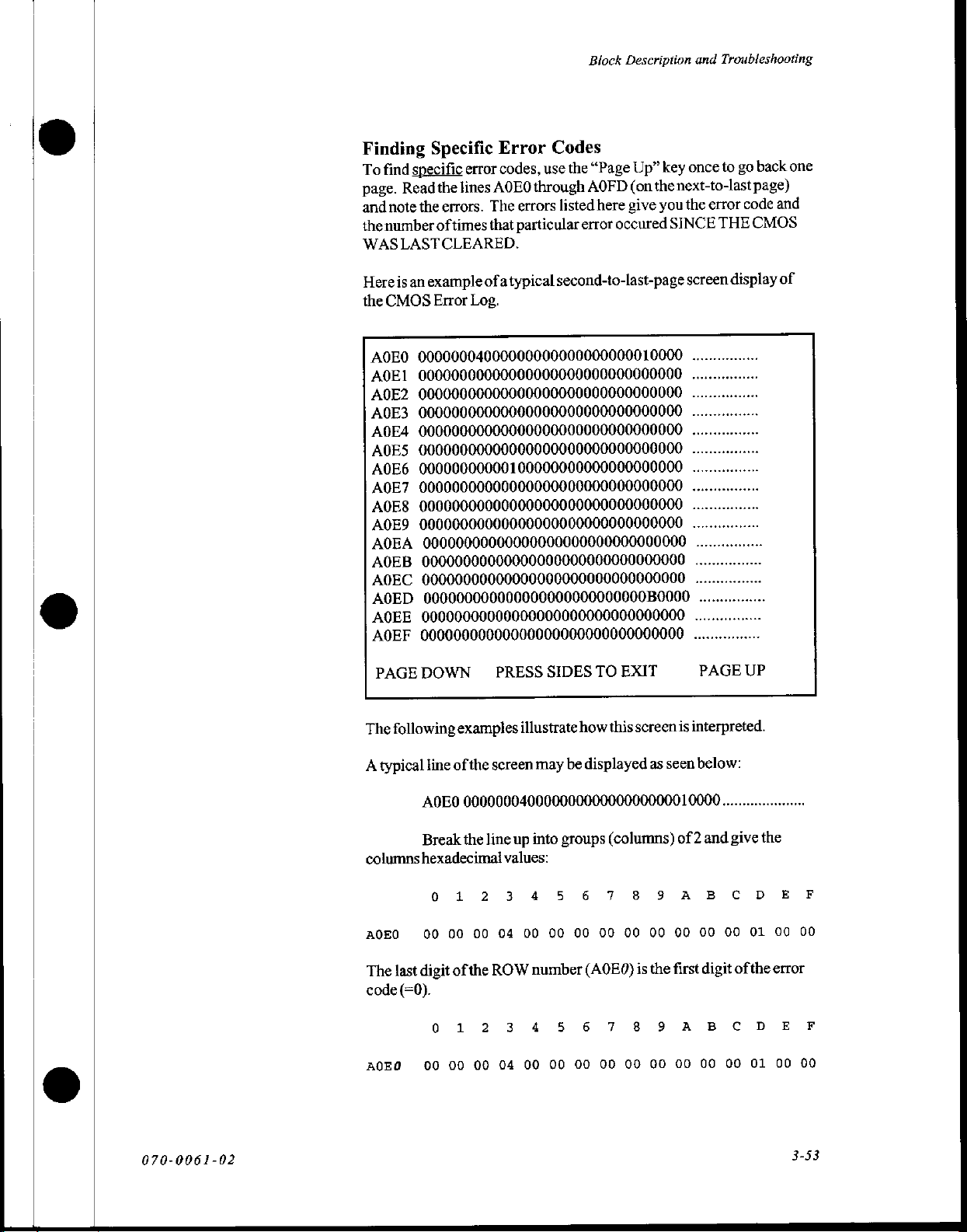
Block
Description
and
Troubleshooting
Finding
specific
find
To
Read
page.
note
and
number
the
WAS
LASTCLEARED.
an
is
Here
CMOS
the
A0E0
A0E1
A0E2
A0E3
A0E4
A0E5
A0E6
A0E7
A0E8
A0E9
AOEA
A0EB
AOEC
AOED
AQEE
AOEF
Specific
the
errors.
the
of
example
Error
00000004000000000000000000010000
00000000000000000000000000000000
00000000000000000000000000000000
00000000000000000000000000000000
00000000000000000000000000000000
00000000000000000000000000000000
00000000000100000000000000000000
00000000000000000000000000000000
00000000000000000000000000000000
00000000000000000000000000000000
00000000000000000000000000000000
00000000000000000000000000000000
00000000000000000000000000000000
000000000000000000000000000B0000
00000000000000000000000000000000
00000000000000000000000000000000
error
lines
times
ofa
Log.
Error
codes,
through
AOEO
errors
The
particular
that
typical
Codes
key
Up”
“Page
the
use
thenext-to-last
(on
AOFD
you
give
here
listed
occured
error
second-to-last-page
back
go
to
once
page)
code
error
the
CMOS
SINCE
THE
display
screen
..
..
..
..
..
..
..
..
.
.
.
....
................
one
and
of
PAGE
DOWN
The
following
A
typical
line
А0ЕО
Break
columns
A0E0
The
code
АОЕО
hexadecimal
0 1 2
00
digit
last
(=0).
0
00 00 00
PRESS
examples
of
the
screen
00000004000000000000000000010000
the
line
04
00
00
ROW
ofthe
1 2
04
SIDES
illustrate
may
up
into
values:
3
4
5 6
00
00
number
3 4
5
00 00 00
TO
how
be
displayed
groups
00
00
(A0E0)
6
00 00
EXIT
this
screen
as
(columns)
7
8 9
00
00
the
is
7 8 9
00
seen
of 2 and
00
first
00
PAGE
UP
is
interpreted.
below:
.....................
give
the
A
A
B C
00
digit
BC
00
00
00
of
DE
01
the
D
01
00
error
E
00
F
00
F
00
070-0061-02
3-53
Page 72
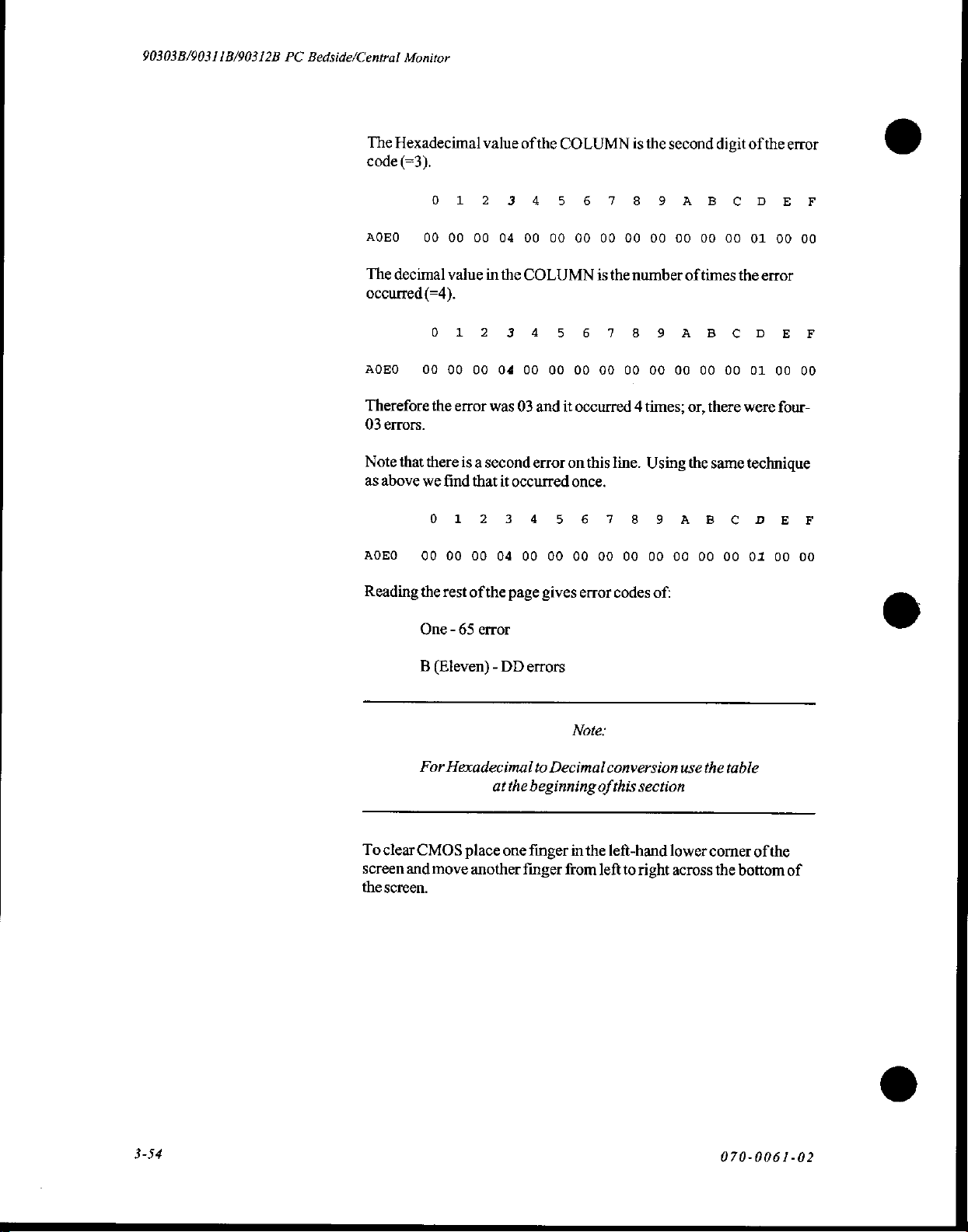
90303B/90311B/90312B
PC
Bedside/Central
Monitor
The
Hexadecimal
code
(=3).
value
ofthe
COLUMN
0
1
2
3
4
5 6 7 8 9
is
the
second
A
BC
digit
ofthe
DE
error
F
AQEO
The
decimal
occurred
ADEO
Therefore
03
errors.
Note
that
as
above
ADEO
Reading
00
00 00
value
(=4).
0
00
00
the
there
we
find
1
2
00 04
error
is a
that
04
00 00
in
the
COLUMN
3
00
was
03
second
it
occurred
00
4
5 6 7
00 00 00
and
it
occurred 4 times,
error on
this
once.
00
is
the
line.
0 1 2 3 4 5 6 7 8
00 00 00
the
rest
One - 65
B
(Eleven) - DD
04
of
the
error
00
page
errors
00 00
gives
00 00 00
error
codes
00 00 00
number
8 9
00
A
00 00
Using
9
A B
00 00 00
of:
00
00
oftimes
B
C
00
00
or,
there
the
same
C
01
00
the
error
DE
01 00
were
four-
technique
DE
01
00
00
F
00
F
00
To
clear
screen
the
screen.
For
Hexadecimal
CMOS
and
move
at
the
place
one
another
Note:
to
Decimal
beginning
finger
in
finger
from
conversion
of
this
the
left-hand
left
to
use
section
lower
right
across
the
table
corner
the
bottom
of
the
of
3-54
070-0061-02
Page 73

Block
Description
and
Troubleshooting
Error
Codes
and
Probable
Causes
ERROR
0000
0001
0002
0003
0004
0005
0006
0007
0008
0009
000A
000B
000C
000D
000E
000F
0010
0011
0012
0013
0014
0015
0016
0017
0018
0019
001A
001B
001C
001D
001E
001F
0020
0021
0022
0023
0024
0025
0026
0027
0028
0029
DESCRIPTION/PROBABLE
Notroubleshooting
VRTX
Task
VRTXNoTCB's
VRTXNo
VRTX
VRTX
VRTX
VRTX
VRTX
VRTX
VRTX
VRTX
VRTX
VRTX
VRTX
VRTX
VRTX
No
troubleshooting
No
Divide
No
Overflow
Array
Bad
No
troubleshooting
No
No
Notroubleshooting
Notroubleshooting
Notroubleshooting
Notroubleshooting
Bad
Bad
Bad
Bad
Rompack,
Notroubleshooting
Notroubleshooting
No
Bad
Bad
Interpreter
Software
Bad
PCBA,
Memory
Not A Memory
Mailbox
Zero
Buffer
WaitC
Invalid
Time
No
Message
Oueue
Oueue
Partition
Initialization
No
Charactor
troubleshooting
by
Zero/Rompack,CPU,
troubleshooting
Interrupt/Rompack,
Interrupt/Rompack
Opcode/Rompack,CPU,Software
troubleshooting
troubleshooting
Packet
Length/CPU
SDLC
Address/
Packet
Code/
Instruction
Modules
troubleshooting
Dictionary
Secondary
Invoked
Packet
Type
Rompack
value
ID
Error/
Rompack
Available/Rompack
Available/
Block/Rompack
In
Use/
Rompack
Message/
Full/
In
Out/
ID
Full/
Rompack
Rompack
Progress/
System
CPU
Error/
ID
CPU
In
Kernal/
Header/
Header/
Received-Interpreter/CPU
Rompack
Call/
Board
Present/
Rompack
Software
Error/
Rompack
Error/
Rompack
Ready/
value
value
value
CPU
value
value
value
value
value
value
value
Board,
CPU
Board,
Board,
CPU
value
value
value
Module
Module
With
Bad
CAUSE
Software
RAM
PCBA
Rompack
Rompack
Software
CPU
Module,
Modules,
Modules,
Board,
Software
Software
Module
Terminator
Terminator
Terminator
Ram
PCBA,
Channel/Module
Board,
Ram
070-0061-02
3-55
Page 74

90303B/90311B/90312B
PC
Bedside/Central
Monitor
ERROR
002A
002B
002C
002D
002E
002F
0037
0038
0043
0044
0045
0046
0047
0048
0049
004A
004B
004C
004D
004E
004F
0050
0051
0052
0053
0054
0055
0056
0057
0058
0059
005А.
005B
005C
005D
DESCRIPTION
SDLC
Bad
Rompack
Channel
Bad
PCBA,
Program
Bad
Rompack
OPEND
Board,
Rx
Buffer
Board/Software
through
0036 - No
Cannot
through
0042 - No
Parity
Error/Rompack,CPU
Or
Alarm
Board,Ram
Notroubleshooting
Notroubleshooting
Notroubleshooting
Notroubleshooting
Notroubleshooting
troubleshooting
No
Node
Eth
Problem/Cabling
Eth_Module_Ch_Dir
Problem/Cabling
Eth_Attach_Channel_Resp
Network
Enable
Eth
Problem/Cabling,
Unknown
Cabling
Directory
Node
Problem/Cabling
Next
Level
PCBA,
Ram
troubleshooting
No
Memory
Board,Ram
Notroubleshooting
Notroubleshooting
Notroubleshooting
No
troubleshooting
Table
Ascii
Notroubleshooting
Notroubleshooting
troubleshooting
No
troubleshooting
No
Notroubleshooting
/PROBABLE
Address-
Interpreter/
Number-
Rompack
/Module,
Index
Tx
Error
PCBA,
Ram
Unavailable
Task - Interpreter
In
Rompack
troubleshooting
Table
Accept
Parse
troubleshooting
PCBA,
Called
Rompack
Record
value
value
value
value
value
value
Resp
Resp
Rompack
Status/
Expecteď/
Dir
Problem/Cabling
Alarm
Return
Length
Does
Link
Rompack
value
PCBA,
Failed
Rompack
Manager
value
value
value
value
Out
Index
value
value
value
value
value
CAUSE
CPU
Interpreter/
CPU
Excessive
SDLC
value
Structure/
value
Invalid
With
CPU
Expected/CPU
Expected/CPU
Expected/
CPU
Board,Network
CPU
Error/
Table
Match
Not
Loading/
SDLC
OfRange/
Module
Board,
Ram
Board,Ram
CPU
Board,Ram
/Module,
Module
PCBA,
CPU
Loading/CPU
Problem
Mod/Channel/
Board,Network
Board,Network
Board,
Board,Network
CPU
Problem/
Board,Network
Size/CPU
Board,
CPU
Problem
©
PCBA,
CPU
ο
O
o
3-56
070-0061-02
Page 75

Block
Description
and
Troubleshooting
|
ο
ο
ο
ERROR
005E
005F
0060
0061
0062
0063
0064
0065
0066
0067
006F
0070
0071
0072
0073
0074
0075
0076
0077
0078
0079
007A
007B
007C
007D
007E
007F
0080
0081
0082
0083
0084
0085
0086
0087
0088
0089
008A,
008B
008C
008D
008E
008F
0900
0901
0902
0903
0904
DESCRIPTION/PROBABLE
Rx
through
No
No
Notroubleshooting
Open
No
No
Notroubleshooting
Notroubleshooting
No
No
Invalid
Tilegal
Notroubleshooting
Notroubleshooting
Notroubleshooting
Notroubleshooting
Notroubleshooting
Interprter
Board,
Notroubleshooting
Bad
Channel
Bad
Module
SDLC
SDLC
Invalid
RUPI
SDLC
006E - No
User
Reset
Notroubleshooting
Notroubleshooting
Notroubleshooting
Notroubleshooting
Notroubleshooting
Notroubleshooting
InitLoop
Nomore
Notroubleshooting
Notroubleshooting
No
troubleshooting
No
troubleshooting
No
troubleshooting
Display
Notroubleshooting
No
troubleshooting
Notroubleshooting
Notroubleshooting
troubleshooting
troubleshooting
Close
Link
Such
troubleshooting
troubleshooting
troubleshooting
Buffer
RamPCBA,
Number
Number
Initial.
Error/CPU
Intr.
Sequence
Final
Packet/
Error
Case/CPU
Tx
Buffer
Overflow/
troubleshooting
Via
Biomed
Error/Software, Display
Display
Interrupt
Link
Channel/
Message
Len/
Buffers/Software
Lost/
Error/
Error/
Software
Type/Network
CPU
Board
Notroubleshooting
Full/SDLC
Rompack
value
Was
Was
Found
Board,
Error/
Module
Board,
Menu/
value
value
value
value
value
value
value
value
value
value
value
Disp.
value
value
value
value
value
value
value
Software
CPU
Board
value
value
value
value
value
value
value
value
value
value
value
CAUSE
Loading,
Found
In A Packet/
In
The
Module
CPU
Board
Problem
Module
CPU
Board
value
Operator
Controller
Controller,
Cabling,
Software,
Software
Packet/
Initiated
CPU
Fanouts
Software
Board
CPU
070-0061-02
3-57
Page 76

90303B/90311B/90312B
PC
Bedside/Central
Monitor
ERROR
0905
0096
0097
0098
0099
009A
009B
009C
009D
009E
009F
00A0
00A1
00Α2
0043
00A4
00A5
00A6
00A7
00A8
00A9
00AA
00AB
00AC
00AD
00AE
00ΑΕ
00B0
00C8
00C9
00CA
00CB
00CC
00D6
00D7
00D8
00D9
00CD
00DA
00DB
00DC
00DD
00DE
OOFA
00FF
DESCRIPTION/PROBABLECAUSE
No
troubleshooting
Bad
Decnet
Node
Config
Multicast
Config
Config
Data
Base
Enable
Msg
Sent
Return
Status
Notroubleshooting
Notroubleshooting
No
troubleshooting
No
troubleshooting
No
troubleshooting
Mfree
Error/Software
No
troubleshooting
No
troubleshooting
Notroubleshooting
Notroubleshooting
Notroubleshooting
Outof32
Notroubleshooting
byte
VRTX
Notroubleshooting
Notroubleshooting
82586
Receive
Error/CPU
Cabling
Ethernet
Lost
Cabling
Interrupt/CPU
Notroubleshooting
CPU
Hung/
82586
Notroubleshooting
Routing
In
Revd.
Msg
through
00C7 - No
troubleshooting
Unrecognized
Yet
DEC
Not
CPU
Net
Feature
Software,
Bad
Message
Msg
Board
Lost
Ncb
Cmd
Ptr/
Software,
Len/
Lost
Invalid
Opcode/
Notroubleshooting
Notroubleshooting
Notroubleshooting
through
00D5
-No
Invalid
Segment
Stack
Gen.
Page
Undefined
Eth
Tss/
Not
Segment
Protect
Fault/
Interrupt/Rompack,CPU
Alarm
troubleshooting
RAM
Present/
Fault/
Rompack,
Multicast
value
ID/
CPU
Error/CPU
Request
Qpost
Failed/
Error/
Error/CPU
value
value
value
value
value
value
value
value
value
value
mem/Software
value
value
value
value
Board,
value
With
to
Supported
Board
Called
Software,CPU
CPU
Rompack
value
value
value
PCBA,
RAM
Error/RAM
Software
RAM
Receive
Board
Board
Board
CPU
Board
CPU
Board
Board,Network
Network
Board,
Network
Problem/Cabling
Use
Zero
Count/
value
NSP/Software
From
Called
Net/Software,
IBM
From
Board
PCBA
Ram
Board,
value
Rompack
PCBA,
PCBA,
Rompack
CPU
(1)Monitor
PCBA
Board
CPU
Error/
Problem/
Problem/
CPU
Net/
IBM
Board
Module
(2)
Board
Board
CPU
3-58
070-0061-02
Page 77

Block
Description
and
Troubleshooting
ERROR
0100
0101
0102
0103
0104
0105
0106
0107
0108
0109
010A
010B
010C
010D
010Е
010F
0110
0111
0112
0113
0114
0115
0116
011N
0118
0119
012C
012D
012E
012F
0130
0131
0132
0108
01C9
01F4
01Е5
01F6
01F6
0258
0259
0260
Not
Notroubleshooting
No
No
No
Notroubleshooting
No
Ts
Ts
VRTX
Notroubleshooting
Bad
Bad
through
through
through
through
Got
through
DESCRIPTION/PROBABLE
Enough
Init
Page
Invalid
troubleshooting
Invalid
troubleshooting
Stack
troubleshooting
Rev
Board
Xmit
Controller,
Invalid
Bad
Ether
Watchdog
Bad
Monitor
OlrExpected
DECNet
Lost
NCB
No
troubleshooting
No
troubleshooting
Msg
DMA
012B - Notroubleshooting
Bad
Magic
No
troubleshooting
Dgisinit
Controller
No
troubleshooting
34010
Display
Controller
01C7 - No
Shared
01F3 - No
CR
child
Got
Bad
Notroubleshooting
0257 - Notroubleshooting
CAagent
Bad
FFFF - No
Ram
For
V86/
Table
Error/
RAM
value
Descriptor
80386
For
PktErr/Touchscreen,
Packet
CPU
blk
Overflowed
Rbint
Physaddr/CPU
Reset
Cmd
Ptr/
Use
Error/
Could
Won't
Controller
troubleshooting
Table
TID/QID
Open
TID/QID
Open
To
Free/RAM
value
Exception/
value
Task/
Software
value
value
Too
Big/
Touchscreen,
Board
Bufmem/
Reguest/
Type/
IBM
Msg/CPU
RAM
Number
Not
Start
Database
troubleshooting
Link
Link
troubleshooting
Error/
Verify
Net/
value
Ptr/
CPU
value
value
PCBA
RAM
In
value
Find
value
Up
Stopped
Table
Response/
value
Table
Response/
CPU
Software,
CPU
Board
Board
PCBA
gap
Working
After
Corrupted/RAM
Rompack
Board,
Dip
Code/
Is
IsCorrupted/
CAUSE
Not
Enough
PCBA
Display
Board
Switch
Board
value
Loading/DisplayControlier
Rcv
Waveform
value
value
Corrupted/
CPU
value
CPU
value
Ram
PCBA
Controller,CPU
Display
CPU
Board
Ram
PCBA,
CPU
Board
Settings
Rompack
Display
Board/Display
Data/Display
PCBA
RAM
Board
RAM
Board
Installed
Rompack
PCBA
PCBA
070-0061-02
Page 78

90303B/90311B/90312B
PC
Bedside/Central
Monitor
Periodic
Maintenance
Periodic
180days.
1.
maintenance
The
Clean
monitor
plug-in
screws)
filter
is
completely
foamas
input
module
damage
Remove
Perform
Carefully
input
modules.
performance.
Visually
Test
the
the
sensor.
checks
following
filter
modules).
and
filter
may
Remove
wash
with
material,
overheating
result
touchscreen
the
safety
verification
observe
operation
Ifnecessary,
check
for
accuracy
ambient
The
light
display
should
steps
describe
(located
water
dry
before
as
air
and
if
foam
is
assembly
sensor
brightness
be
performed
the
necessary
underneath
filter
and
from
mild
monitor,
the
monitor
soap.
reinstallation.
cannot
easily
pass
possible
permanent equipment
used.
and
clean
face
tests
previously
of
the
monitor
run
functional
of
display
by
alternately
should
and
intensity
covering
vary
approximately
procedure.
directly
(held
Make
certain
Donot
substitute
through.
of
CRT,
ifrequired.
described,
any
active
tests
to
verify
and
clarity.
and
with
each
every
below
by
four
the
Patient
patient
monitor
exposing
change.
3-60
070-0061-02
Page 79

Options
|
à
e
Section
Patient
Overview
Data
4:
Logger
Options
The
Patient
Medical's
patient
printers
RS232
printout
The
and
Data
Logger
PC
Bedside
vital
signs
and terminals.
serial
communications
as
line-at-a-time
PC
Bedside
other
computer
data
Monitor
equipment
with
(PDL)
is a software
patient
Monitor
directly
Data
applicable
to
is
transmitted
ports
images
is
medical
connected
using
Note:
(Model
compatible
through
and
is
formatted
standard
equipment.
to
medical
standards.
option
to
90303B).
external
the
devices,
one
onto a screen
ASCII
All
cables,
monitor
SpaceLabs
PDL
transmits
such
of
the
monitor's
or
characters.
printers,
must
comply
as
070-0061-02
41
Page 80
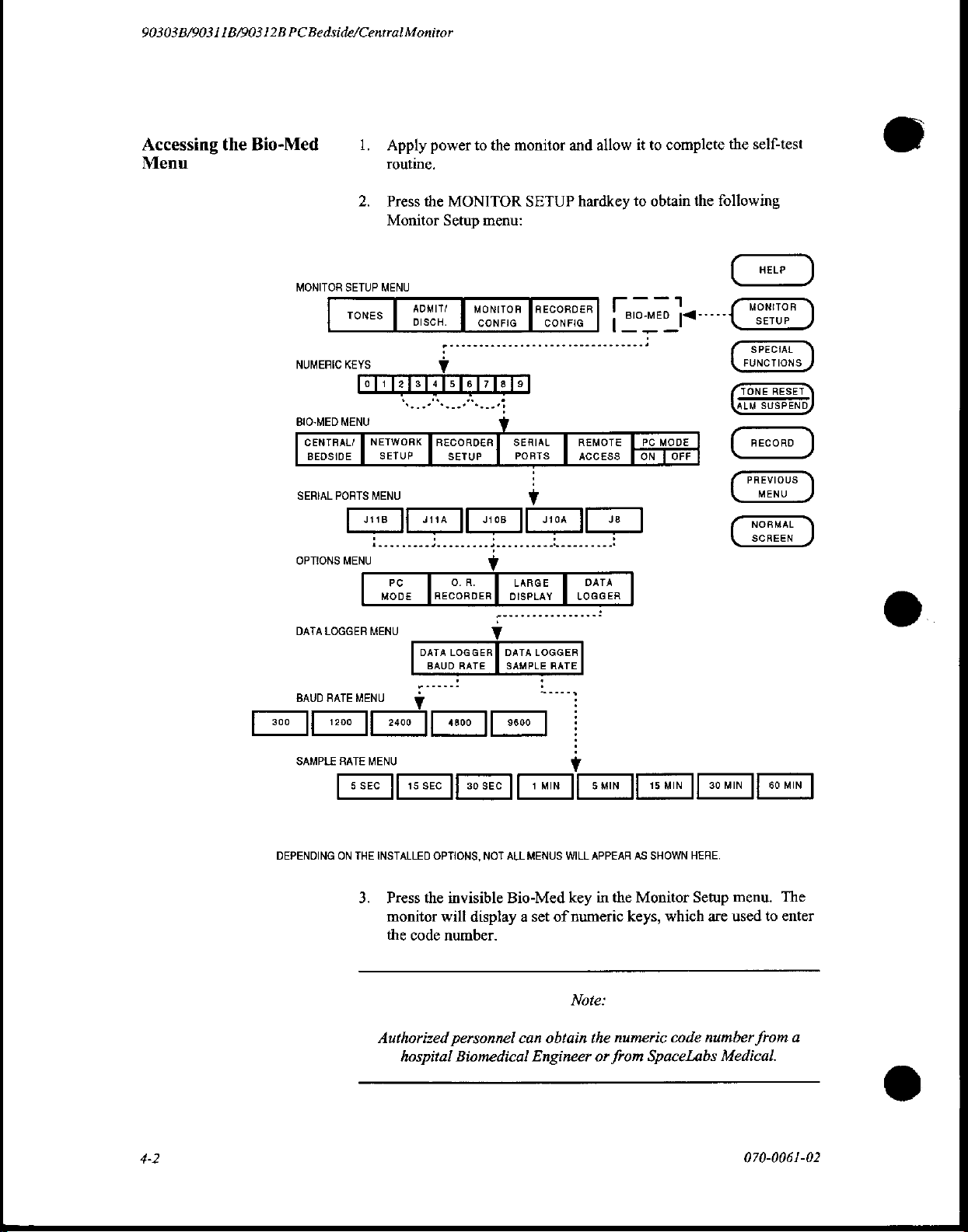
90303B/9031 1B/90312B
PC
Bedside/Central
Monitor
Accessing
Menu
the
Bio-Med
MONITOR
NUMERIC
BIO-MED
CENTRAL/ | NETWORK J RECORDER
BEDSIDE
SERIAL
OPTIONS
DATA
BAUD
Pa ο |
1.
Apply
routine,
2.
Press
Monitor
SETUP
TONES
MENU
KEYS v
MENU
SETUP
PORTS
MENU
|
J11B
MENU
MENU
Ji
İl
PC
MODE
2400
MENU
LOGGER
RATE
1200
power
the
MONITOR
Setup
ADMITS
DISCH.
SETUP
4114
JÍ
RECORDER
DATA
LOGGERJ
BAUD
γ
=
to
the
menu:
MONITOR
CONFIG CONFIG
J10B
i
O.
R.
DISPLAY
y
DATA
RATE
SAMPLE
Il
9600
monitor
SETUP
JRECORDER
SERIAL
PORTS
È
J10A
LARGE
LOGGER
RATE
9“
]
and
allow
hardkey
REMOTE
ACCESS
I:
DATA
LOGGER
it
to
T
|
BIO-
一 一 一
PC
ON Î OFF
J8
|
to
complete
obtain
MED
|
MODE
the
the
following
self-test
©
©
4-2
SAMPLE
DEPENDING
RATE
MENU
| 5 SEC | 15
ON
THE
INSTALLED
3.
Press
monitor
the
Authorized
hospital
SEC
OPTIONS,
the
code
Il
30
SEC
NOT
invisible
will
display a set
number.
personnel
Biomedical
JÍ 1 MIN
ALL
MENUS
Bio-Med
can
obtain
Engineer
|| 5 MIN
WILL
key
of
numeric
Note:
APPEAR
in
the
the
numeric
or
from
il
15
MIN | 30
AS
SHOWN
Monitor
keys,
which
SpaceLabs
HERE.
Setup
code
ΜΙΝ
menu.
are
used
number
Medical.
070-0061-02
Ji
60
to
from
MIN
|
The
enter
a
Page 81
4.
Enter
screen
Bio-Med
5.
Press
display,
JI1A/B
See
information.
6.
Select
7.
Press
options
8.
Press
Rate
the
code
number.
remains
the
represent
"Connecting
the
the
for
the
menu,
menu
SERIAL
where
desired
DATA
setting
DATA
and
unchanged.
will
J8
LOGGER
LOGGER
select
If
an
If
display.
PORTS
represents
the
to
serial
the
9-pin
an
External
port.
baud
the
key.
ports
key.
rate
BAUD
desired
incorrect
the
correct
The
the
25-pin
of
the
Device"
The
Options
The
and
RATE
baud
number
number
Serial
port,
Dual
in
Data
the
sample
key
rate.
is
Ports
and
Serial
this
chapter
menu
Logger
rate.
to
entered,
is
entered,
menu
will
J10A/B
Port
for
will
display.
menu
display
Options
the
the
and
Option.
more
includes
the
Baud
The
combination
carefully.
transmissions,
large
number
same
time,
some
may
limit
the
9.
To
return
the
PREVIOUS
again.
10.
Press
the
Sample
11.
Using
the
then
back
information
will
again
Slow
of
range
to
DATA
Rate
power
ON.
go
of
PDL
baud
may
cause
patient
devices
of
sample
data
the
Data
MENU
LOGGER
menu,
switch
This
into
memory
through
Note:
baud
rate
rates,
in
loss
of data.
vital
signs
cannot
readings
and
procedure
rates
Logger
key.
select
on
the
and
the
self-test
accept
from
menu
SAMPLE
and
sample
combination
This
data
is
being
data
at
at
which
your
the
monitor.
to
set
the
The
Data
Logger
RATE
the
desired
monitor,
loads
restarts
turn
the
configuration
the
monitor.
routine.
rate
must
with
frequent
is
especially
monitored.
high
baud
device
sample
menu
key
to
sample
the
monitor
be
rates,
can
rate,
will
display
rate.
memory
The
selected
data
true
if
a
At
the
so
this
accept
press
display
the
OFF
and
monitor
070-0061-02
4-3
Page 82

90303B/90311B/90312B
Data
Printouts
PC
Bedside/Central Monitor
Each
line
terminated
you
are
column
line.
This
around
try
condensing
printer.
Two
types
The
page
patient
following
*
the
transmitted)
*
monitored
*
patient
*
current
of
the
data
printout
with
line
feed
and
monitoring a large
printer,
feature.
name,
end
the
data
will
be
handled
If
you
the
printer's
of
information
header
appears
bed
number,
situations
of a page
name
date
occur:
vital
or
changes
signs
bed
from
prefer
at
is
reached
number
may
contain
carriage
number
one
automatically
that
type
are
transmitted:
the
and
parameters
return
of
parameters
reading
by
each
data
or
using a wide
top
of
each
date. A new
(i.e.,
50
change
changes
up
to
132
characters.
and
may
require
the
printer
reading
carriage
page
headers
page
and
page
is
data
lines
characters
Note
that
you
have
more
than
if
it
has a wrap-
all
fits
on
one
(132
column)
and
data
contains
generated
have
the
when
been
and
is
if
an
80-
one
line,
lines.
the
Troubleshooting
Problem
DATA
not
menu.
Improper
spacing.
No
printed
Garbled
LOGGER
appear
data
is
on
or
in
Monitor
spacing
being
displayed
external
lost
data.
key
does
Setup
or
double
device.
Data
Each
data
Possible
Monitor
option.
PDL
retum/line
end-of-line.
may
or
Power
Device
properly.
Faulty
improperly.
may
lines
are
transmitted
data
line
contains
collected
interface
not
problem
cable.
be
for
each
Causes
not
configured
sends a carriage
feed
sequence
The
external
be
set
up
or
may
not
be
Parity
Baud
inappropriate.
at
the
time
vital
sign
for
the
at
each
device
properly.
faulty
cables.
set
up
set
rate
settings
the
interval
that
parameter
specified
data
was
collected
being
monitored.
Solution
Contact
configure
Set
feed.
Check
Ensure
line"
port
Check
at
device.
assignments
connections.
Check
rate
SpaceLabs
monitor.
external
power
that
device
mode
and
requirements
for
RS232
the
monitor
Check
cables.
and
parity
at
configuration.
as
well
as
Medical
device
for
"0"
and
cables.
is
in
"on
that
RS232
are
satisfied.
compatibility
and
the
external
monitor
and
Verify
settings.
port
port
baud
the
to
line
4-4
070-0061-02
Page 83
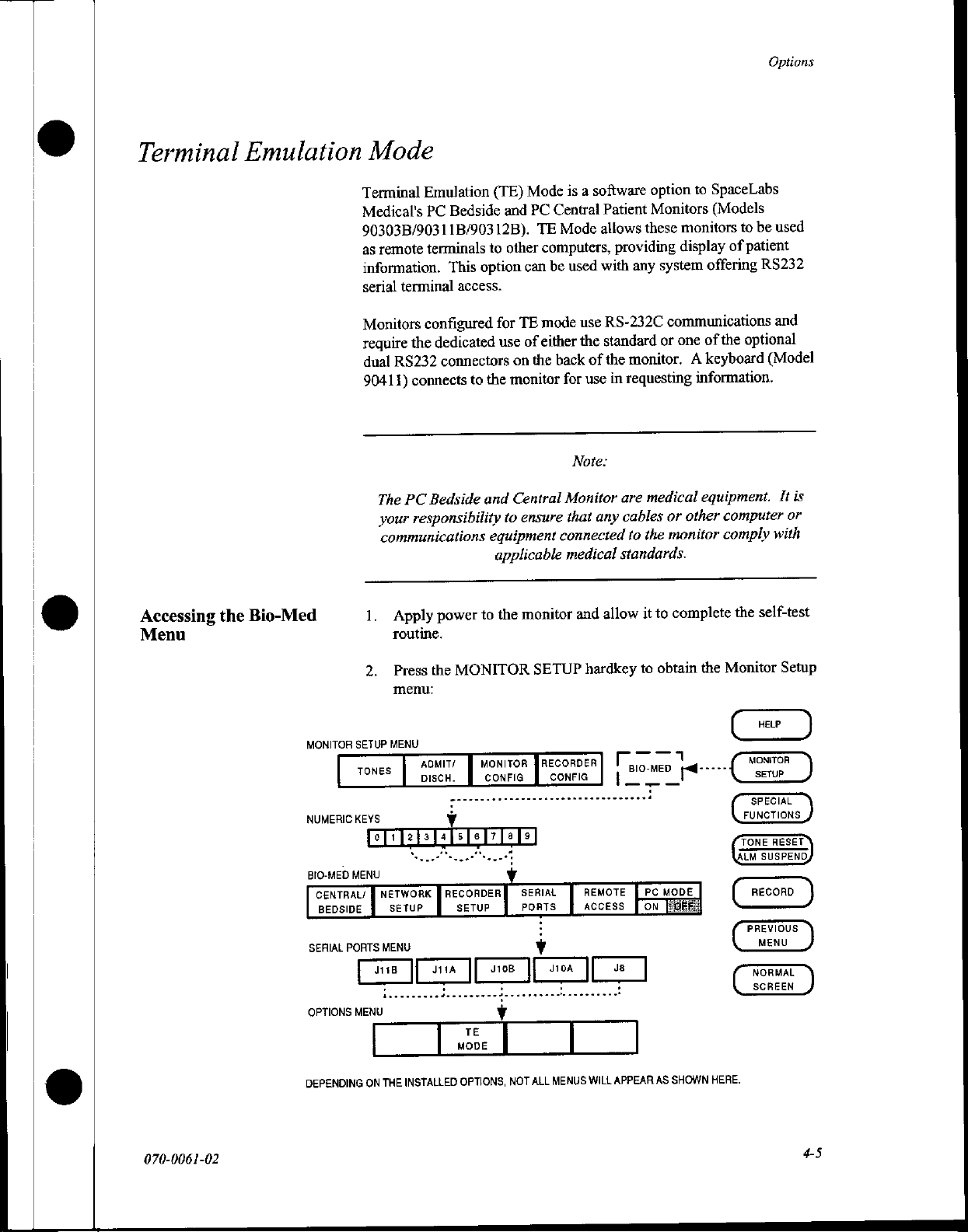
Options
Terminal
Emulation
Mode
Bedside
to
option
This
access.
the
to
and
equipment
(TE)
and
other
for
use
monitor
to
applicable
Terminal
Medical's
90303B/90311B/90312B).
as
information.
serial
Monitors
require
dual
90411)
Emulation
PC
remote
The
your
terminals
terminal
configured
dedicated
the
RS232
communications
connectors
connects
Bedside
PC
responsibility
Mode
Central
PC
TE
computers,
be
can
mode
TE
either
of
back
the
on
Central
ensure
software
a
is
Patient
allows
Mode
providing
with
used
RS-232C
use
standard
the
the
of
in
use
for
Note:
Monitor
any
that
connected
medical
option
Monitors
monitors
these
display
system
any
communications
one
or
medical
other
or
monitor
the
A
monitor.
requesting
are
cables
to
standards.
SpaceLabs
to
(Models
used
be
to
patient
of
offering
of
keyboard
information.
equipment.
RS232
optional
the
(Model
computer
comply
and
It
with
is
or
Accessing
Menu
the
Bio-Med
MONITOR
NUMERIC
BIO-MED
CENTRAL/
BEDSIDE
SERIAL
OPTIONS
1.
2.
SETUP
TONES
KEYS
MENU
PORTS
MENU
Apply
routine.
Press
menu:
MENU
NE
回
NETWORK
§
SETUP
MENU
回
monitor
the
to
power
MONITOR
the
ADMIT/
DISCH.
`
|
MONITOR
CONFIG
: :
Y
回
自
-
RECORDER
SETUP
τε
MODE
SETUP
RECORDER
fl
CONFIG
回
回
回
回
ㆍ
há
SERIAL
PORTS
γ
|
γ
and
hardkey
REMOTE
ACCESS
allow
Г
BIO-MED
complete
to
it
obtain
to
a
pa
ED
MODE
PC
E
Monitor
the
raff-----
self-test
the
MONITOR
SETUP
SPECIAL
FUNCTIONS
RESET
TONE
SUSPEND,
ALM
RECORD
MENU
NORMAL
SCREEN
Setup
DEPENDING
070-0061-02
THE
ON
INSTALLED
OPTIONS,
NOT
ALL
MENUS
WILL
APPEAR
AS
SHOWN
HERE.
y
5
A
Page 84
90303B/9031
1B/903
12B
PC
Bedside/Central
3.
Monitor
Press
the
monitor
the
enter
invisible
will
display
number.
code
Bio-Med
a
set
of
key
in
numeric
Note:
the
Monitor
keys,
Setup
which
are
menu.
used
to
The
o
Authorized
hospital
4.
Enter
screen
Bio-Med
5.
After
PORTS
represents
represent
diagrams
6.
Select
7.
Press
8.
Using
then
information
will
personnel
Biomedical
the
code
remains
menu
verifying
key.
the
the
are
the
desired
the
TE
the
power
back
ON.
into
again
go
can
number.
unchanged.
display.
will
that
PC
The
Serial
standard
9-pin
ports
provided
serial
MODE
key.
switch
This
procedure
memory
through
obtain
Engineer
If
an
incorrect
If
Mode
is
Ports
25-pin
of
the
"Connecting
in
port.
The
on
the
and
restarts
the
self-test
the
numeric
or
from
correct
the
turned
menu
will
serial
port,
Dual
Serial
to
Options
monitor,
loads
the
the
routine.
code
number
SpaceLabs
number
number
OFF,
display,
and
Port
External
an
menu
turn
is
press
J10A/B
Option.
will
the
monitor
Medical.
entered,
entered,
is
the
where
configuration
monitor.
The
from
the
the
SERIAL
J8
and
JI1A/B
Pin-out
Device".
display.
OFF
and
memory
monitor
a
©
4-6
070-0061-02
Page 85
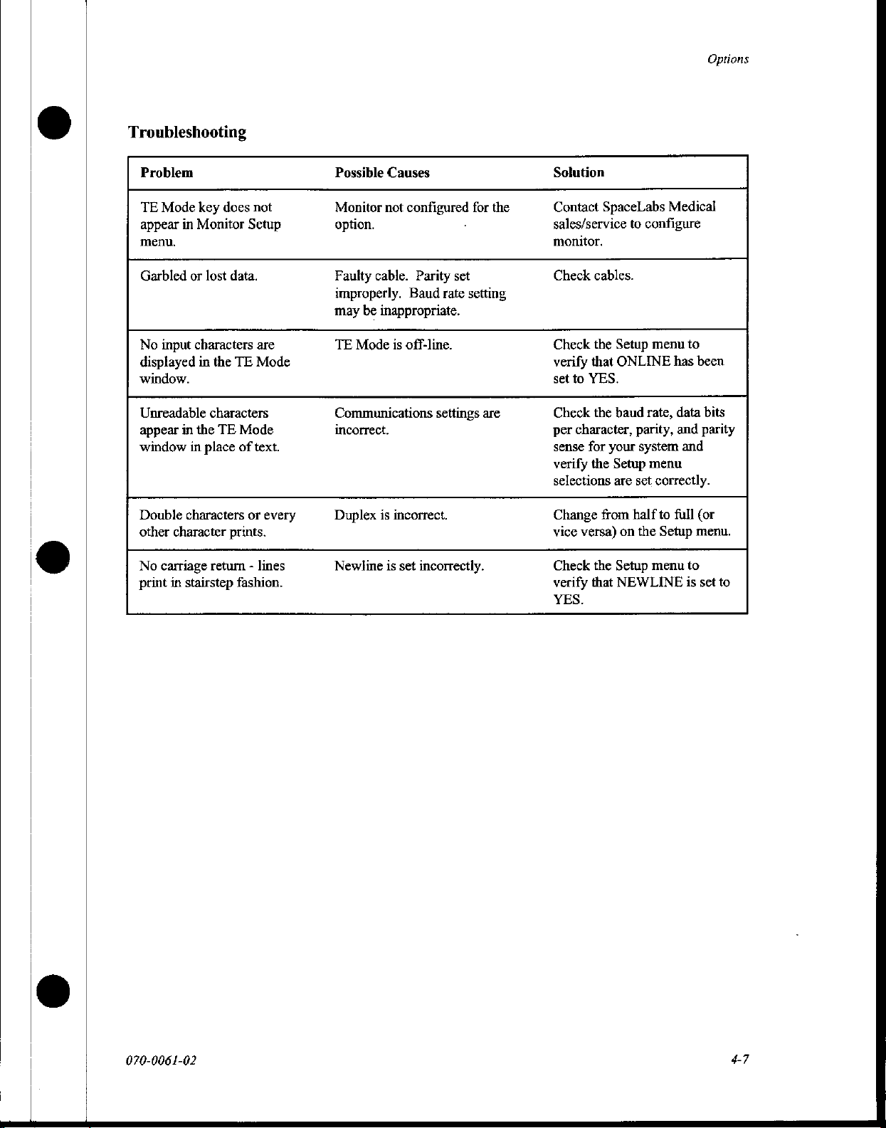
Troubleshooting
Problem
TE
Mode
key
does
appear
in
Monitor
menu.
Garbled
No
displayed
window.
Unreadable
appear
window
Double
other
No
print
or
lost
input
characters
in
in
the
in
place
characters
character
carriage
in
stairstep
data.
the
TE
characters
TE
prints.
return - lines
fashion.
not
Setup
are
Mode
Mode
of
text.
or
every
Possible
Monitor
option.
Faulty
improperly.
may
TE
Communications
incorrect.
Duplex
Newline
Causes
not
configured
cable.
Parity
Baud
be
inappropriate.
Mode
is
off-line.
is
incorrect.
is
set
incorrectly.
for
・
set
rate
setting
settings
are
the
Solution
Contact
sales/service
monitor.
Check
Check
verify
set
Check
per
sense
verify
selections
Change
vice
Check
verify
YES.
SpaceLabs
to
cables.
the
Setup
that
ONLINE
to
YES.
the
baud
character,
for
the
versa)
that
your
from
the
parity,
Setup
are
set
half
on
Setup
NEWLINE
system
the
Medical
configure
menu
to
has
been
rate,
data
bits
and
parity
and
menu
correctly.
to
full
(or
Setup
menu.
menu
to
is
set
Options
to
070-0061-02
4-7
Page 86
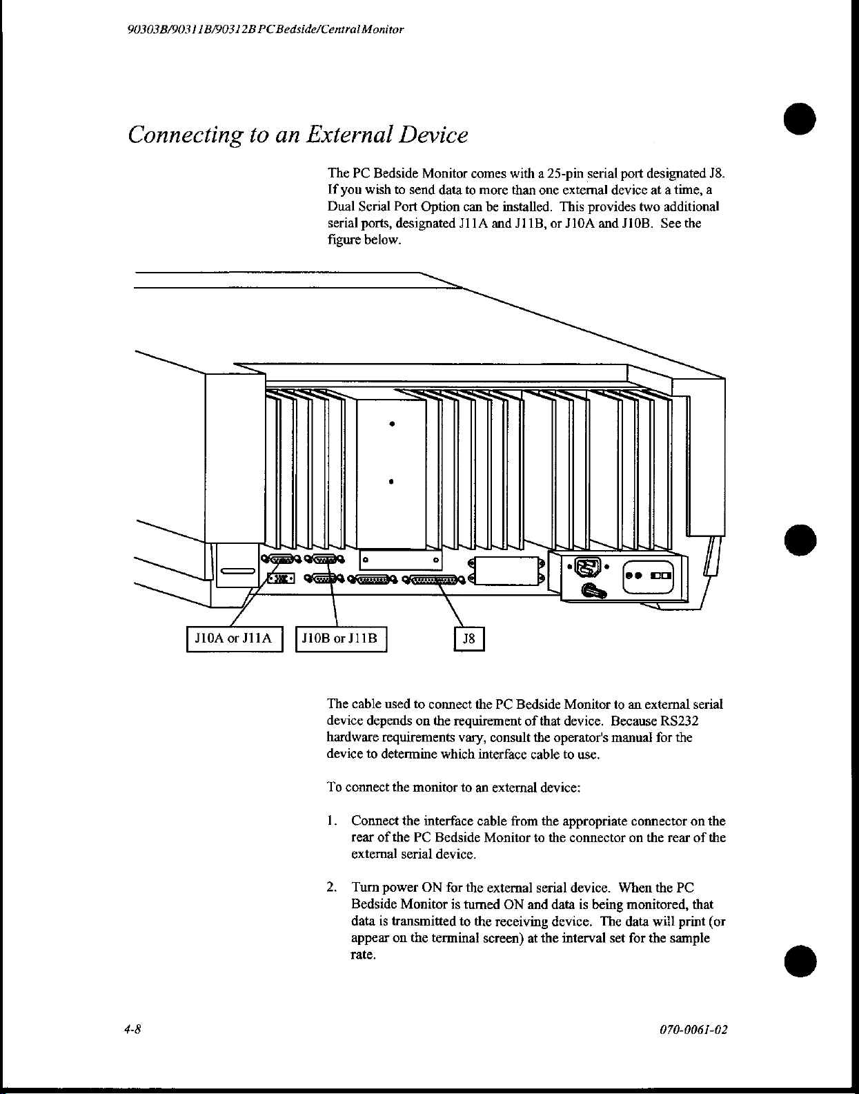
90303
B/903 1 1B/90312B
PC
Bedside/Central
Monitor
Connecting
一
號
to
an
External
The
If
Dual
serial
figure
PC
you
Serial
Bedside
wish
ports,
below.
Device
Monitor
to
send
data
Port
Option
designated
oe
comes
to
more
can
J11A
with a 25-pin
than
be
installed.
and
J11B,
serial
port
one
external
This
or
JIOA
See]
device
provides
and
two
Ji0B.
designated
at a time,
additional
See
J8.
a
the
©
J10A
or
J11A
J10B
The
device
hardware
device
To
2.
or
J11B
cable
connect
1.
Connect
rear
external
Turn
Bedside
data
appear
rate.
used
to
depends
to
on
requirements
determine
the
monitor
the
interface
of
the
PC
serial
power
ON
Monitor
is
transmitted
on
the
38
connect
terminal
the
the
requirement
vary,
which
to
an
Bedside
device.
for
the
is
turned
to
the
PC
Bedside
of
consult
interface
cable
Monitor
external
screen)
the
cable
external
from
to
ON
and
receiving
at
Monitor
that
device.
operator's
to
use.
device:
the
appropriate
the
connector
serial
device.
data
is
device.
the
interval
to
Because
manual
When
being
The
set
an
external
RS232
for
the
connector
on
the
rear
the
PC
monitored,
data
will
print
for
the
sample
serial
on
the
of
the
that
(or
©
4-8
070-0061-02
Page 87

Options
e
©
Cable
Pin-outs
3.
If
you
OFF.
store
The
25-pin
designated
Connector
Chassis
TX
RX
RTS
CTS
DSR
Signal
SD
DTR
CD
RI
DTR
*
(either
Output
Input
Output
Input
Input
Ground
Input
Output
Input
Input*
RI
Input
A
Ground
or
wish
to
stop
data
transmission,
Do
not
set
the
printer
the
monitored
serial
port
Ji1A
and
is
installation-selectable
B,
but not
data
designated
J11B,
25-Pin
一
BUN
WwW
OIA
'
'
20
both).
for
or
J10A
9-Pin
(A)
im
WA
KA
ma
O
一
off-line
printing
J8
and
and
for
as
when
the
J10B,
9-Pin
(B)
一
only
turn
this
Dual
are
one
the
external
causes
returned
the
Serial
Port
wired
as
ge
26
90
90
90
20
20
29
96
26
20
ος
of
the
9-pin
device
printer
on-line,
option,
shown:
Pin
25
Pin
00000
Pin
1
ports
to
9
0000
070-0061-02
49
Page 88
90303B/90311B/90312B
PC
Bedside/Central
Monitor
Additional
90303
Monitor
PCMS
(PC)
Options
Bedside
-01
PC
Mode/Local
1.
Access
2.
Requires
3.
If
parallel
90303(A)(B).
boards.
Optional
Monitor
representative.
Use
Mode,
those
-02
PC
1.
Access
the
2.
Requires
3.
One
additional
dual
Options
Optional
Monitor
representative.
Use
Mode,
those
to
parallel
or
must
the
Bio-Med
then
ports.
Mode/Network
to
same
serial
serial
-03
must
the
Bio-Med
then
ports.
patient
90410
or
additional
dual
serial
See
90411
keyboard.
be
use
PIVOT
patient
LAN.
90410
port
(J8)
serial
board(s)
and
90411
keyboard.
be
use
PIVOT
Access
data
is
limited
Disk
Drive
serial
boards
options
configured
menu
data
Disk
peripheral
-05
configured
menu
-03
to
assign
software
Access
is
available
Drive
is
standard
must
be
for
configurations
to
assign
software
to
the
Module.
peripheral
must
be
incorporated
and
-05
for the
by
your
local
which
to
assign
from
Module.
with
the
devices
are
incorporated
by
your
local
which
to
assign
local
bedside
devices
configuration
customer
serial
ports
COM1,
all
bedside
monitor.
used,
additional
in
the
of
these
customer
serial
ports
COM1,
monitor
are
used,
additional
in
the
service
belong
COM2,
monitors
If
90303(A)(B).
boards.
are
COM2,
to
etc.
parallel
parallel
service
assigned
etc.
only.
of
these
PC
to
within
or
or
See
to
to
PC
-03
Parallel
Allows
Parallel
Two
installed,
Monitor
representative.
-04
Analog
1.
Provides
2.
Typical
3.
Monitor
representative.
4.
Ifthe
slots,
those
Board
for
boards
parallel
must
Output
use
must
VIDCO
and
slots.
attachment
can
ports
Options
be
configured
hi-level
is
for
be
configured
system
pressures
of a single
be
installed
(maximum)
-04
and
-05
analog
waveforms
the
VIDCO
is
used,
must
have
parallel
in
J10
per
are
not
by
your
remote
by
your
modules
specific
device
or
J11.
monitor.
possible.
local
customer
from
the
display
local
customer
must
labels
such
If
two
parallel
service
installed
system.
service
be
placed
(ART,
as a printer.
ports
modules.
in
specific
CVP,
PA),
070-0061-02
are
etc.
in
Page 89
-05
Dual
Serial
Board
1.
Allows
ports,
2.
One
DCE.
3.
Up
of
4.
If
possible,
Dual
bal
6.
Monitor
representative.
7.
Serial
8.
Use
-06
Terminal
1.
Provides a window
computer.
Requires
らい
Requires a dedicated
ま
Not
Monitor
の
representative.
Use
>
Mode.
for
configured
RS-232C
to
two
five
(5)
two
dual
serial
must
port
a.
PC
b.
TE
c.
Data
d.
VIDCO
the
Bio-Med
Emulation
90411
compatible
must
the
Bio-Med
attachment
additional
RS-232C
serial
boards
users
Mode
Mode
Logger
as
DTE.
port
(J8)
dual
ports.
boards
are
be
configured
are:
(See
Option
(See
Option
(See
Large
Display
menu
on
keyboard.
RS-232C
with
Option
be
configured
menu
of
up
to
four
comes
with
serial
boards
are
installed,
installed
Option
(serial
monitor’s
to
in
by
your
-01/-02).
-06).
-26).
(See
Option
ports)
port,
-01
or
by
your
assign
(4)
additional
the
90303(A)(B)
may
Options
J10
or
J11.
local
-07).
to
assign
screen
to
configured
-02
(PC
local
the
applicable
RS-232C
be
added
-03
and
customer
users
display
customer
as
Mode).
serial
data
DTE.
(serial)
configured
for a maximum
-04
are
not
service
to
the
ports.
from a host
service
port
to
TE
Options
as
-07
PC-VIDCO
1.
Provides
the
VIDCO
2.
Provides
installed.
3.
Requires
4.
Monitor
representative.
5.
Cables
-08
Six-Trace
1.
Requires
2.
Requires
and
3.
Monitor
representative.
required:
a.
Analog
b.
RS-232C
fast
ROM
RS-232C
serial
data
Remote
numerics
|
dedicated
must
be
Output
to
PC
Monitor
3.50.xx
10MHz
Pack.
must
be
out
to
dedicated
Display.
only.
Analog
RS-232C
configured
to
SAU:
SAU:
012-0060-XX
(or
above)
(20MHz
configured
XTAL)
RS-232C
Output
port
configured
by
your
local
012-0058-XX
(XX=cable
software
by
your
for
CPU,
local
port
(Option
as
customer
entire
26MHz
customer
for
numerics
-04)
must
DCE.
service
length
in
network.
display
service
on
also
be
feet)
controller,
070-006
1-02
4-11
Page 90

90303
B/90311B/90312B
PC
Bedside/Centrai
-10
1.
2.
>
し
4.
5.
6.
7,
-13
1.
2.
Monitor
Calcs
and
Tabular
Data
available
only
installed.
Requires
Requires
Provides
Provides
3.62.43EN
436-0009-01
the
following
a.
Hemodynamic
b.
Oxygenation
c.
Respiratory
d.
Renal
e.
Drug
Dose
trend
(Ventilation)
information
selectable 1 minute
Data from
(GDS)
Monitor
local
that
must
(bedside)
the
graphic
be
configured
representative.
Three-Trace
Requires
Monitor
representative.
PC
3.50.xx
must
be
Monitor
(or
configured
Trends
from
the
(or
above)
CPU
drawer
calculations:
in
to
3-hour
monitor
trends
by
above)
software
by
PC
bedside
software.
monitor
assembly.
tabular
format
resolution.
only.
This
feature
your
uses.
local
for
your
local
-
for
24
is
the
customer
entire
network.
customer
in
which
hours
same
service
service
option
is
with
database
©
-14
Four-Trace
1.
Requires
2.
Monitor
representative.
-20
Data
Shuttle
1.
Requires
2.
Monitors
representative.
3.
Only
90470
Data
Shuttle.
-26
Patient
1.
Provides
serial
2.
(J8)RS-232C
3.
Patient
4.
Use
option,
5.
Monitor
Data
(RS-232C)
data
the
Bio-Med
then
representative.
-30
Alarm
1.
2.
Relay
Part
number
Provides
alarm.
PC
Monitor
3.50.xx
must
be
configured
3.53.38EN,
must
be
modules
Logger
an
ASCII
port.
port
limited
select
must
be
configured
306684-003.
an
alarm
(or
above)
or
above,
configured
with
data
stream
is
standard
to
bedside
menu
to
assign
the
baud
relay
to
trigger
software
by
by
1.05.33EN
with
rate
by
for
your
local
(PC)
or
equivalent.
your
local
(or
in a predefined
the
monitor,
monitor
your
with
the
applicable
and
desired
local
customer-provided
entire
network.
customer
customer
above)
format
the
serial
sample
customer
service
service
software
to a dedicated
configured
PDL
option.
port
rate.
service
light
support
as
DCE.
for
the
or
audible
©
PDL
4-12
070-0061-02
Page 91
-51
Bedside
1.
Provides
the
monitor.
Requires
network.
Requires
Monitor
representative.
Use
fileserver's
Not
Bedside
NOT
Chart
PC
Chartmaster
a.
The
controller,
the
b.
The
must
the
Bio-Med
compatible
Chart
require
a
touchscreen
a
90825
or
one
of
the
following:
10MHz
and
PC
Mode
436-0009-01
be
configured
menu
name
to
the
with
software
PC
Mode
window
(90825
or
90827)
90827
(PC
(20MHz
memory
Options
XTAL)
fast
ROM
bank
CPU
drawer
by
(application
bedside
-01,
is
located
to
run.
which
allow
from
Chartmaster)
CPU,
26MHz
pack.
The
CPU
and
the
bank-select
assembly.
your
local
customer
mode)
to
monitor.
-02,
-06,
-07.
in
the
ROM
users
to
a
90303(A)(B)
on
the
same
display
board
must
PAL
service
assign
the
pack,
and
Options
interact
with
also
have
installed,
DOES
90311
Monitor
90312
Monitor
PCMS
PCMS
(PC)
(PC)
Central
Central
Four-patient
-12
Calcs
1
Data
2.
Requires
3.
Requires
4
Provides
Provides
selectable
Data
(GDS)
Monitor
representative.
Eight-patient
1.
CPU
0003-xx
N
0104-xx
Monitor
representative.
five-trace
and
available
3.62.43EN
436-0009-01
the
a.
Hemodynamic
b.
Oxygenation
©.
Respiratory
d.
Renal
e.
Drug
trend
from
that
must
ten-trace
Drawer
or
308160-002).
or
must
central
Tabular
1-minute
remote
the
436-0009-xx.
equivalent
Trends
from
any
(or
CPU
following
Dose
information
remote
be
is
either
ROM
be
calculations:
(Ventilation)
to
3-hour
bedside
graphic
configured
central
1OMHz
pack
foreign
configured
monitor.
PC
bedside
above)
software.
drawer
in
tabular
resolution.
monitors.
trends
by
your
monitor.
(20MHz
Display
must
be
ROM
by
your
monitor
assembly
format
This
feature
local
controller
either
pack.
local
on
for
is
the
uses.
customer
CPU
XTAL)
must
a
672-1000-xx
customer
the
network.
24-hours
same
database
service
P/N
be
26MHz.
service
with
436-
or
672-
(P/
070-0061-02
4-13
Page 92

90303B/90311B/90312B
Bedside/Central
PC
Monitor
CALCS
-12
Data
1.
2.
Requires
Requires
3.
4.
Provides
Provides
5.
1-minute
Data
6.
(GDS)
Monitor
7.
representative.
and
available
a.
b.
c.
d.
e.
from
that
Tabular
any
from
3.62.43EN
436-0009-01
the
following
Hemodynamic
Oxygenation
Respiratory
Renal
Drug
trend
to
3-hour
remote
the
must
(or
(Ventilation)
Dose
information
resolution.
bedside
remote
configured
be
Trends
Bedside
PC
above)
CPU
calculations:
graphic
software.
Drawer
tabular
in
monitors.
trends
your
by
monitor
Assembly
format.
the
is
This
feature
customer
local
network.
the
on
24-hour,
same
uses.
©
selectable
database
service
070-006
1-02
Page 93

Section
NON-A
CPU
CPU
RESETPCBA-foralINON-ACPU
ETHERNET
IRTS
SDLC
RAM
RAM
FUSE,
DISPLAY
DISPLAY
Z-AXIS(PIGGY
X/Y
X/Y
POWER
A.C.
PRE-REGULATOR
DC/DCCONVERTER
TOROID
A.C.SWITCH
A.C.SWITCH
DIODE
POWER
PRE-REGULATOR
DC/DCCONVERTER
TOROID
A.C.
A.C.SWITCH
A.C.
DIODE
CRT(order
CRTSOCKETPCBA
DEFLECTION
TOUCHSCREEN
CRT
HVPS
MODULE
FAN-NON-A
FANFILTER
12-VOLTRECHARGEABLE
LITHIUM
SPEAKER
MONITORS
DRAWER
DRAWER
RUPI
CHIP
RUPI
CHIP
PIGGYBACK
PIGGYBACK
1
AMP-
CNTRLR-
CNTRLR-
DEFL.
H.S.
DEFL.
H.S.
(for
use
SUPPLY
POWER
TRANSFORMER
BRIDGE
SUPPLY
TRANSFORMER
SWITCH
SWITCH
BRIDGE
also
FILTER
-
366109-002
BACKPLANE
BATTERY
nn
STACK
SWITCH
PUSHBUTTON
PUSHBUTTON
PUSHBUTTON
PUSHBUTTON
BOARD
306698-001,
YOKE
(order
Monitors...
5:Parts
ASMBLY
ASMBLY
ASSEMBLY
(for
all
(for
al!
PCBA
PCBA
(for
IRTS)
(EARLY,
(EARLY,
BACK)
ASSEMBLY
ASSEMBLY
with
Power
ASSEMBLY
PCBA
PCBA...
RECTIFIER
ASSEMBLY - w/o
PCBA
PCBA
-
RECTIFIER.......................
.…
A:
ASSEMBLY
also
...
List
-
(NON-A
-
(NON-A
306794-xxx
306794-xxx
(Standard
(PC-Mode
-
FOR
-
-
Supply
PCBA
(foruse
....
....
..
-non-A/B
(for
use
DUST
334-0162-00,
PCBA - NON-A/and A MONITORS...
BATTERY.
90303/90311
90312/90303-08
Drawer
-for
w/oZ-AXIS
w/oZ-AXIS
306210-003/-004
EARLY
CURRENT
306299-002
-
w/FAN
SHAFT
......
SHAFT
...............................
with
SEAL)
ГУ...
(BLACK,
Assembliesonly
NON-A
CPU
Drawers)...
CPU
Drawers)
config,
config
(can
(non-A
w/Power
(the
Slide
FAN
(non-A
..
(the
Slide
Power
Supply
..
forNON-A,
“Hard-Key
Monitors,
Monitors,
CPU
Drawers
. .
512K)
....
1-MEG).
Piggyback
Piggyback
only
attached,
attached,
ONLY
&
MONITORS).........
Supply
Bar)
Bar).
rennes
be
used
119-0040-00[12])
306295-003)
eee
.
MONITORS)
3
A/B
label)
8
MHz(16
10
ee
25
26
with
Power
MONITORS)
MHz
XTAL)
MHz(20
МН2)90303/90311
MHz)
Supply
.
MHz
XTAL)
90312/90303-08
306295-003)
…
306289-001
.
шиншилл
........
306794-003
.
306794-006
308225-001
306315-001
.
364050-002
364100-029
.
306181-004
670-0217-00
.
380101-010
.....
306210-003
306210-004
306445-001
..
306285-002
or
119-0177-00
....
306295-003
.
306580-001
.
306235-002
.
306245-002
.
306850-001
....
306824-001
+.
362114-001
.
378000-173
306299-002
306235-002
306245-002
306854-001
....
306824-001
…
362114-001
308230-001
378000-173
…
362112-001
…
306705-002
306609-001
…
306732-002
306722-101
...
306250-004
306618-003
306952-001
384225-002
…
384322-001
384379-001
070-0061-02
5-1
Page 94

Bedside/Central
90303B/90311B/90312B
A/B
MONITORS
DRAWER
CPU
CPU
DRAWER
90312
ALL
CHIP
RUPI
IRTS
CHIP(ALL
RUPI
SDLC
ETHERNET
FUSE,IAMP-(forIRTS).....................
CPUDRAWER
DISPLAY
DISPLAY
DEFLECTIONH.S.
X/Y
X/YDEFLECTIONPCOBA
POWER
MISC.
AC
P.S.PCBA
TOROIDTRANSFORMER-A/BMONITORS
SWITCH
A.C.
SWITCH
A.C.
DIODE
CABLES
(See
POWER
ACMISC.
PCBA-
P.S.
TOROIDTRANSFORMER
A.C.SWITCHBOARD
SWITCH
A.C,
DIODE
CRT(order
CRTSOCKETPCBA.........................
DEFLECTION
TOUCHSCREEN
FILTER
CRT
TOUCHSCREEN
CRT
HVPS
MODULE
MODULE
FAN
FANFILTER..............
12-VOLT
LITHIUM
CHIP
CONTROLLER/Z-AXIS
CONTROLLER/Z-AXIS
SUPPLY
PCBA
A/BMONITORS................
-
BRIDGE
SUPPLY
PCBA
A/B
BRIDGE
also
-
FILTER-
366109-002
BACKPLANE
BACKPLANE
η
ο
RECHARGEABLEBATTERY
BATTERY
PC
ASMBLY
ASMBLY
AND
436-0003-XX
(ALL
436-0003-XX
ASSEMBLY
ASSEMBLY
ASSEMBLY
ASSEMBLY
MONITORS
A/B
-
(FOR
BOARD
BOARD
section
MONITORS
BOARD
306698-001,
YOKE
(also
(also
πο
-
-(REPLACES
RECTIFIER
the
for
ASSEMBLY
A/BMONITORS
-
(FORUSE
-
(REPLACES
-
RECTIFIER
ASSEMBLY
ASSEMBLY
order
ASSEMBLY
order
μμ
.
ALL
-
-
90303-08
(ALL
-(Surface-Mount
............
-
USE
Power
-“B”
Surface
(
-
....
DUST
(BLACK,
334-0155-00
(GRAY,
334-0162-00
PCBA
PCBA-
μμ
μμ
Monitor
90303/90311
Monitors
A/B
Drawers)
CPU
Drawers)
CPU
436-0003-XX
(CURRENT,
-
(CURRENT,
-
-CURRENT
ii
MONITORS
A/B
W/P.S.
Supply’s
A/BMONITORS
W/P.S.
.
-non-A/andAMonitors.................
forall
119-0040-00
308230-003)..
cables)
MONITORS
........................
MountComponents,
119-0040-00
308230-003)
NON-A,
for
“Hard-Key”
A/B
for
“Hard-Key
Monitors
B
Monitors,
A/B
SMHz(16MHz
1OMHz(20MHzXTAL)
....
..
Drawers)
CPU
eee
Technology)
MHz)90303/90311
25
MHZ)
26
..
...
een
...
90312
..
AND
..................
[-12])
and
..
single
.......................
and
.
Monitors)
A/B
label)
Monitors)
label
(accepts
.....
adjustment
[-12])
..
..
Double-High
A
ο
XTAL)
..
A/B
90303-08
pot)
ie
Modules)
E
E
436-0003-00
........
...436-0003-04
364050-002
364100-029
…
307566-001
....
380101-010
436-0009-00
.
308160-001
.
308160-002
..
AB
.
306289-001
306585-001
.
119-0040-00
...
anes
306910-002
308105-001/101
.
308063-100
iii
308230-003
.
670-041
378000-173
119-0040-12
3069
.
670-0620-01
308063-100
308230-003
eee
670-041
378000-173
..
..
1-00
10-002
362112-001
306705-002
306752-002
306722-101
306752-003
306722-101
EE
..384322-001
.
384379-001
1-00
070-0061-02
Page 95

CHASSIS
Top
Assembly
Parts
List
NON-A
TOP
TOP
BOTTOM
BOTTOM
RIGHT
LEFT
BEZEL
DOOR,MODULECAGE
HINGE
LABEL,
LABEL,
A/B
TOPCOVER - A/B
BOTTOM
BEZEL - A/B
DOOR,MODULECAGE
HINGE
DIVIDER,
LABEL,
LABEL,
MONITORS
COVER
COVER - INNER(Sheet
SIDE
MONITORS
-NON-A
COVER - (w/o
COVER
SIDE
COVER - (NON-A
COVER - (NON-A
-(NON-A
PIN..
CRT
FILTER - (Touchscreen
POWER
COVER - A/B
Monitors....
PIN..
MODULE
CRT
FILTER - (Touchscreen
POWER
Monitors
metal)
NON-A
Slide
Bar
POWER
-(w/
Slide
Bar
POWER
Monitors)
Monotors
Monitors
SWITCH - (Mains
Monitors
SWITCH - (Mains
......
..
“Hard
On/OFF)
(Original
Monitors
CAGE - (90306 & all
Colors)
“Hard
OWOFF)
Monitors.
SWITCH
SWITCH
...
Keys”)
B-Monitors
Keys”).
....
..
only).
306732-002
.
306788-002
306780-003
306780-002
...334-0155-00
306995-001
....200-0042-00
...432-0006-00
203-0011-00
.
306769-002
.
306766-001
…
306767-001
...426-0019-00
334-0155-00
....
306995-001
A/B
MONITORS
TOPCOVER
BOTTOM
BEZEL
DOOR,
HINGE
SPRING...
DIVIDER,
LABEL,
COMMON
KEYBOARDHOLEPLUG.....................
CRT
FILTER
DUSTSEAL......................
ROMPACKS/W
ROMPACK
DISPLAY
FOOT
FAN
FILTER
12-VOLT
LITHIUM
- A/B
COVER
-A/B
Monitors.........
MODULECAGE
PIN...
MODULE
CRT
FILTER - (Touchscreen
TO
(mustalso
PLASTICGUIDE
CONTROLLER
-SELF-ADHESIVE
.....................
RECHARGEABLEBATTERY
BATTERY
(New
Monitors
(BASE)-
Colors)
A/B
Monitors.
CAGE - (B-Monitors
ALL
MONITORS
order
Touchscreen
LABEL
....
..
...
BRACKET
.
only)
“Hard
eee
Label
....
Keys”)
..
334-0155-00
or
334-01
62-00)
.....
...200-0127-00
432-0013-02
203-0032-02
202-0014-01
…
306766-001
....
306767-001
426-0034-01
...334-0162-00
κανα
360417-001
...
306722-101
306698-001
306946-001
....
306952-001
...
384225-002
384322-001
…
384379-001
070-0061-02
5-3
Page 96
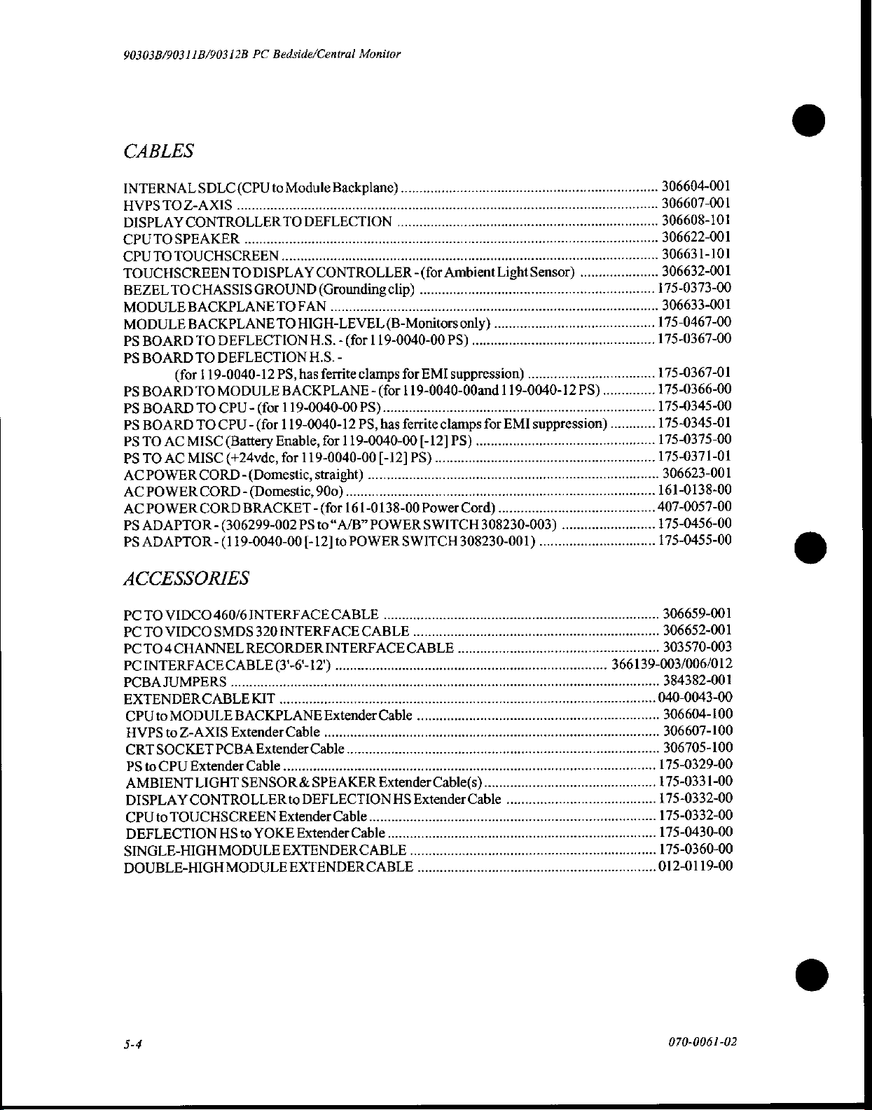
90303B/90311B/90312B
CABLES
PC
Bedside/Central
Monitor
INTERNALSDLC(CPUto
TOZ-AXIS
HVPS
DISPLAY
CPUTOSPEAKER
CPU
TOUCHSCREEN
BEZEL
MODULE
MODULE
PS
BOARD
PS
BOARD
PS
BOARD
PSBOARDTOCPU-(f0r119-0040-00P5)....................
PS
BOARD
PS
TO
PS
TO
ACPOWERCORD-(Domestic,
AC
AC
PS
ADAPTOR - (306299-002
PS
ADAPTOR - (119-0040-00
CONTROLLER
TO
TOUCHSCREEN
TO
CHASSIS
BACKPLANETOFAN...
BACKPLANE
TO
DEFLECTION
TO
DEFLECTION
(for
119-0040-12
TO
MODULE
TO
CPU - (for
AC
MISC
AC
MISC
POWER
POWER
CORD-
CORD
TO
(Battery
(+24vde,
BRACKET - (for
Module
eee
TO
DEFLECTION
ssa
DISPLAY
GROUND
(Domestic,
CONTROLLER - (for
(Grounding
TO
HIGH-LEVEL
HS. - (for
HS.
PS,
has
ferrite
BACKPLANE - (for
119-0040-12
Enable,
for
119-0040-00
straight)
900)
PS
to“A/B”
[-12]to
Backplame)
een
clip)
Ambient
....
(B-Monitors
119-0040-00
-
clamps
PS, has
for
119-0040-00
........................
161-0138-00
POWER
for
119-0040-00and 1 19-0040-12
ferrite
[-12]
PS)
.....................
POWER
SWITCH
only)
PS)
EMI
suppression)
clamps
[-12]
PS)
...
nr
Power
SWITCH
308230-001)
encenar
een
Cord)
ACCESSORIES
mseracaeea
Light
Sensor)
.
for
EMI
suppression)
...
....
308230-003)
.
PS)
eee
nenene
....
.
.
.
.
175-0373-00
....
…
175-0467-00
...
175-0367-00
…
175-0367-01
175-0366-00
...175-0345-01
…
.
407-0057-00
...
306604-001
306607-001
306608-101
306622-001
306631-101
306632-001
306633-001
175-0345-00
175-0375-00
175-0371-01
306623-001
161-0138-00
175-0456-00
175-0455-00
PC
TO
VIDCO
PC
TO
VIDCO
PCTO4CHANNEL
PC
INTERFACECABLE
PCBA
JUMPERS
EXTENDERCABLEKIT
CPU
to
HVPS
to
CRT
SOCKET
PS
to
CPU
AMBIENTLIGHT
DISPLAY
CPU
to
DEFLECTION
SINGLE-HIGH
DOUBLE-HIGH
460/6
SMDS
................
MODULE
Z-AXIS
TOUCHSCREEN
Extender
PCBA
Extender
CONTROLLER
HS
MODULE
MODULE
INTERFACE
320
INTERFACE
RECORDER
(3'-6'-12')
...
BACKPLANE
Cable
Extender
Cable
.....
SENSOR
to
Extender
to
YOKE
EXTENDER CABLE
EXTENDER
CABLE
INTERFACECABLE
..
Extender
........
Cable
..
£
DEFLECTION
Cable
Extender
Cable.........
CABLE
Cable
xtender
CABLE
..
....
HS
Extender
....
.
Cable(s).
Cable
..
+...
306659-001
.
306652-001
....
303570-003
39-003/006/012
....
384382-001
...040-0043-00
....
306604-100
.
306607-100
.
306705-100
175-0329-00
175-0331-00
175-0332-00
....
175-0332-00
...
175-0430-00
175-0360-00
...012-0119-00
5-4
070-0061-02
Page 97
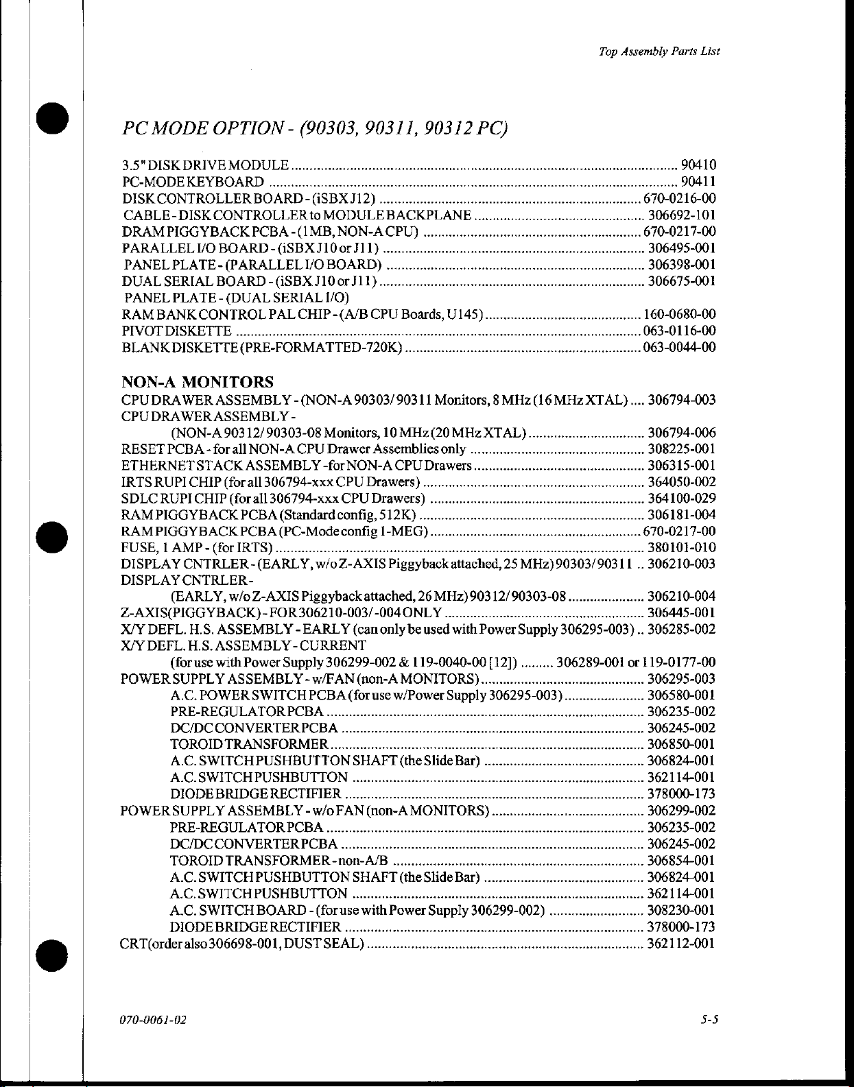
PC
MODE
3.5"
DISK
PC-MODE
DISK
CONTROLLER
CABLE-DISK
DRAM
PARALLEL
PANEL
DUAL
PANEL
RAM
PIVOT
BLANKDISKETTE(PRE-FORMATTED-720K)
PIGGYBACK
PLATE - (PARALLEL
SERIAL
BANK
DISKETTE
OPTION - (90303,
DRIVE
KEYBOARD
PLATE - (DUAL
MODULE
BOARD - (iSBX
CONTROLLER
PCBA
I/O
BOARD - (iSBXJ10
BOARD - iSBX
SERIAL
CONTROL
PAL
iii
to
-(1
I/O
CHIP
MODULE
MB,
BOARD)
J10
or
I/O)
-(A/B
NON-A
or
90311,
J12)
BACKPLANE
CPU)
J11)
....
J11)
CPU
90312
Boards,
.…
PC)
U145)
Top
Assembly
…
670-0216-00
-
306692-101
670-0217-00
.
306495-001
.
306398-001
...
306675-001
160-0680-00
…
063-0116-00
...063-0044-00
Parts
…
90410
…
90411
List
NON-A
CPU
CPU
RESET
ETHERNET
IRTS
SDLC
RAM
RAM
FUSE, 1 AMP - (for
DISPLAY
DISPLAY
Z-AXIS(PIGGYBACK)-
Х/У
X/Y
POWER
POWERSUPPLY
CRT(order
MONITORS
DRAWER
DRAWER
(NON-A
PCBA - for
RUPI CHIP
RUPI CHIP
PIGGYBACK
PIGGYBACK
(EARLY,
БЕРИ.
DEFL.H.S.
(for
SUPPLY
A.C.
PRE-REGULATOR
DC/DCCONVERTER
TOROIDTRANSFORMER
A.C.SWITCH
A.C.SWITCHPUSHBUTTON
DIODE
PRE-REGULATOR
DC/DCCONVERTERPCBA
TOROID
A.C.
A.C.SWITCHPUSHBUTTON
A.C.
DIODE
ASSEMBLY
ASSEMBLY
903
STACK
(for
(for
CNTRLER-(EARLY,w/0Z-AXIS
CNTRLER
w/oZ-AXIS
H.S.
ASSEMBLY - EARLY
ASSEMBLY
use
with
ASSEMBLY
POWER
BRIDGE
ASSEMBLY - w/o
TRANSFORMER
SWITCH
SWITCH
BRIDGE
also
306698-001,
-
12/90303-08
all
NON-A
ASSEMBLY
all
306794-xxx
all
306794-xxx
PCBA
(Standard
PCBA
(PC-Mode
IRTS)
-
FOR
Power
Supply
SWITCH
PCBA
PUSHBUTTON
RECTIFIER
PCBA
PUSHBUTTON
BOARD - (for
RECTIFIER
DUSTSEAL)..................
-
(NON-A
Monitors,
CPU
Drawer
-for
Piggyback
3062
10-003/-004
-
CURRENT
306299-002
-
w/FAN
PCBA
..
PCBA
.....
..
-non-A/B
90303/
NON-A
CPU
CPU
config,
config
(can
(for
..
SHAFT
..
....
FAN
..
SHAFT
....................
use
90311
10
MHz(20
Assemblies
CPU
Drawers)
Drawers)
512K)
1-MEG)..
Piggyback
attached,
ONLY
only
be
dz
(non-A
use
(the
(non-A
with
Power
iii
MONITORS)
w/Power
MONITORS)
.
(the
Monitors, 8 MHz
MHz
only
Drawers....
....
..
.
attached,
26
MHz)90312/90303-08...
...
used
with
119-0040-00
Supply
Slide
Bar)
Slide
Bar)
iii
Supply
(16
XTAL)...
25
MHz)90303/90311
..
Power
Supply
[12])
.........
306295-003)
.
306299-002)
MHz
XTAL)....
306295-
306289-001
.
003)
306794-003
…
306794-006
.
308225-001
…
306315-001
....
364050-002
.
364100-029
.
306181-004
670-0217-00
....
380101-010
..
306210-003
306210-004
....
306445-001
..
306285-002
or
119-0177-00
….
306295-003
306580-001
306235-002
306245-002
306850-001
….
306824-001
...
362114-001
378000-173
306299-002
306235-002
306245-002
306854-001
-…
306824-001
....
362114-001
308230-001
....
378000-173
362112-001
070-0061-02
5-5
Page 98
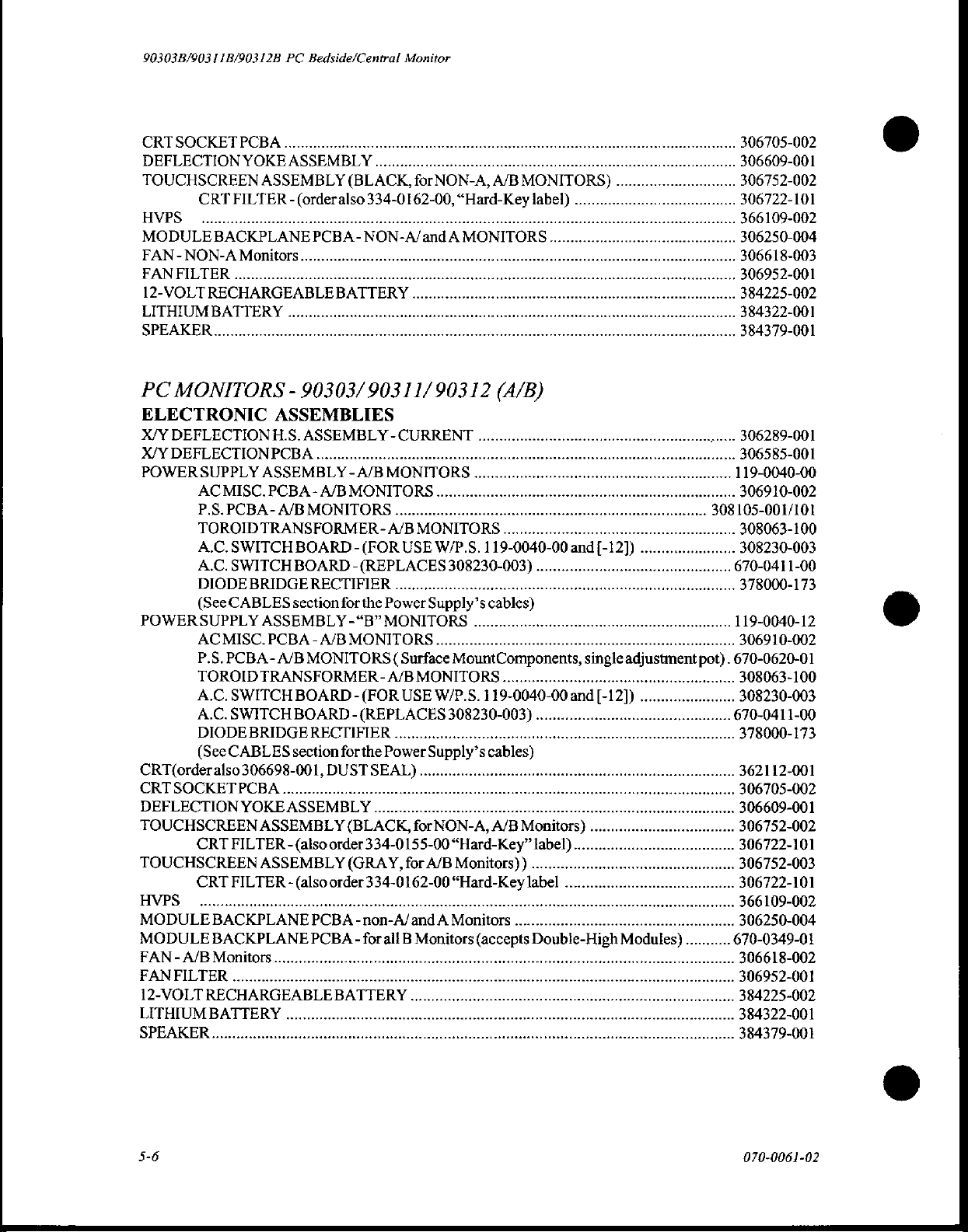
90303B/90311B/90312B
CRT
SOCKET
DEFLECTION
TOUCHSCREEN
CRT
FILTER - (orderalso
HVPS
MODULE
FAN
FANFILTER
12-VOLT
LITHIUM
PC
ELECTRONIC
X/Y
X/Y
POWER
POWER
CRT(order
CRT
DEFLECTION
TOUCHSCREEN
TOUCHSCREEN
HVPS
MODULE
MODULE
FAN - A/B
FANFILTER
12-VOLT
LITHIUM
이 스 니 느 니 니 아
BACKPLANE
-NON-A
.................
RECHARGEABLE
BATTERY
MONITORS - 90303/90311/90312
DEFLECTION
DEFLECTION
SUPPLY
AC
MISC.
P.S.
PCBA-
TOROIDTRANSFORMER
A.C.
SWITCH
A.C.
SWITCH
DIODE
(See
CABLES
SUPPLY
ACMISC.
P.S.
PCBA - A/B
TOROIDTRANSFORMER
A.C.
SWITCH
A.C.
SWITCH
DIODE
(See
CABLES
also
SOCKET
............................
PCBA
CRT
FILTER - (also
CRT
FILTER - (also
BACKPLANE
BACKPLANE
Monitors
...........
RECHARGEABLEBATTERY
BATTERY
PC
Bedside/Central
PCBA
YOKE
ASSEMBLY
ASSEMBLY
나 아 이 이 아 이 마 이
PCBA-
Monitors
BRIDGE
BRIDGE
306698-001,
YOKE
.
.
ASSEMBLIES
H.S.
ASSEMBLY - CURRENT
PCBA
ASSEMBLY - A/B
PCBA - A/B
A/B
MONITORS
BOARD - (FOR
BOARD - (REPLACES
RECTIFIER
section
ASSEMBLY
PCBA - A/B
MONITORS
BOARD-
BOARD - (REPLACES
RECTIFIER
section
DUST
ASSEMBLY
ASSEMBLY
order
ASSEMBLY
PCBA
PCBA-
.
.
Monitor
.....
(BLACK,
마 이 마 마 어 마 마
BATTERY
MONITORS
for
-“B”
MONITORS
(FOR
for
334-01
아 마 아 아 마 마 아 아
NON-A/and A MONITORS
MONITORS.
..........
-
A/B
USE
the
Power
MONITORS
(
Surface
-
A/B
USE
for
the
Power
SEAL)....
(BLACK,
334-0155-00“Hard-Key”
(GRAY,
order
eee
-non-A/and A Monitors
forall B Monitors
for
334-0162-00
NON-A,
62-00,
“Hard-Key
아 아 아 아 아 아 아 아 아 어 아이
....
..
MONITORS..
W/P.S.
308230-003)
Supply’s
MountComponents,
MONITORS
W/P.S.
308230-003)
Supply’s
for
NON-A,
A/B
Monitors))
“Hard-Key
(accepts
A/B
MONITORS)
label)
(А/В)
119-
.
cables)
119-0040-00
.
i
cables)
A/B
Monitors)
label)
.........
label
..
Double-High
..
and
..
.
single
[-12])
..
Modules)...
adjustment
…
306705-002
306250-004
306618-003
..
306952-001
...
384225-002
384322-001
384379-001
306289-001
306585-001
….
119-0040-00
siens
306910-002
-
308105-001/101
..
308230-003
‘670-0411-00
378000-173
….
119-0040-12
306910-002
pot).
670-0620-01
308063-100
..
308230-003
.670-0411-00
an
378000-173
362112-001
306705-002
-
306250-004
....670-0349-01
5-6
070-0061-02
Page 99
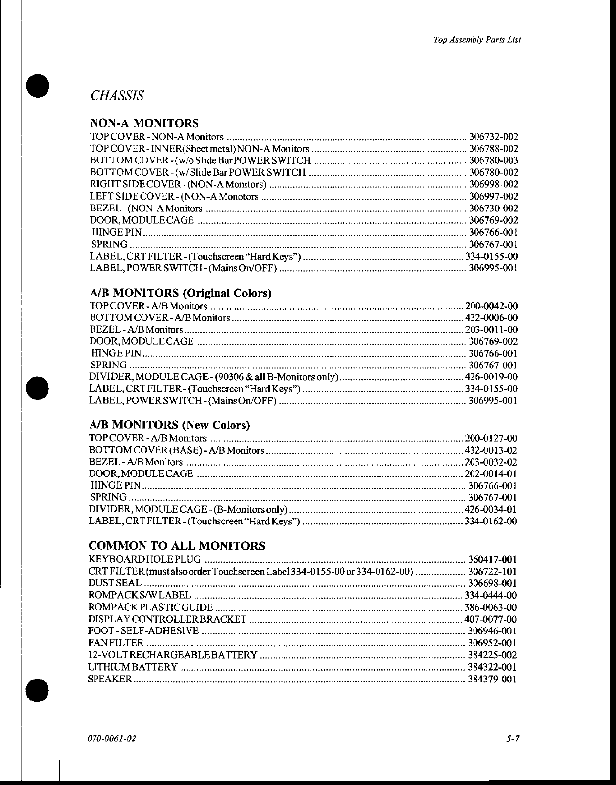
CHASSIS
Top
Assembly
Parts
List
NON-A
TOP
TOP
BOTTOM
BOTTOM
RIGHT
LEFT
BEZEL
DOOR,
HINGE
A/B
TOPCOVER - A/B
BOTTOM
BEZEL - A/B
DOOR,
HINGE
MONITORS
COVER - NON-A
COVER
MONITORS
-INNER(Sheet
COVER
COVER
SIDE
COVER - (NON-A
SIDE
COVER - (NON-A
-(NON-A
MODULECAGE
PIN...
COVER - A/B
Monitors
MODULE
PIN..
LABEL,
LABEL,
CRT
FILTER - (Touchscreen
POWER
Monitors
-(w/o
-(w/
Slide
Monitors
(Original
Monitors
Monitors
CAGE
SWITCH-
metal)
Slide
Bar
Bar
...
-(
(Mains
NON-A
POWER
POWER
Monitors)
Monotors
Colors)
.…
“Hard
On/OFF)
Monitors
SWITCH
SWITCH
....
all
B-Monitors
Keys”).
..
.
only).
306732-002
.
306788-002
.
306780-003
.
306780-002
.
306998-002
306997-002
306730-002
.
306769-002
.
306766-001
.
306767-001
334-0155-00
306995-001
....200-0042-00
....432-0006-00
....203-0011-00
.
306769-002
.
306766-001
.
306767-001
426-0019-00
334-0155-00
...
306995-001
A/B
MONITORS
TOPCOVER-
BOTTOM
BEZEL - A/B
DOOR,
HINGE
DIVIDER,
LABEL,
COMMON
KEYBOARDHOLEPLUG
CRT
DUSTSEAL........................
ROMPACKS/W
ROMPACK
DISPLAY
FOOT - SELF-ADHESIVE
FANFILTER
12-VOLTRECHA
LITHIUM
MODULECAGE
FILTER
ABMonitore
COVER
Monitors........
PIN...
MODULE
CRT
FILTER - (Touchscreen
TO
(mustalso
PLASTICGUIDE
CONTROLLER
....
BATTERY
(BASE)-
ALL
LABEL
(New
CAGE
order
....
..
MONITORS
BRACKET
...
....
Colors)
A/B
Monitors
-(B-Monitors
Touchscreen
only)...
“Hard
.
Keys”)
Labe)
..
nie
200-0127-00
...432-0013-02
203-0032-02
202-0014-01
.
306766-001
.
306767-001
426-0034-01
...334-0162-00
….
360417-001
.
306722-101
.
306698-001
...334-0444-00
...386-0063-00
407-0077-00
.
306946-001
.
306952-001
.
384225-002
.
384322-001
...
384379-001
070-0061-02
5-7
Page 100
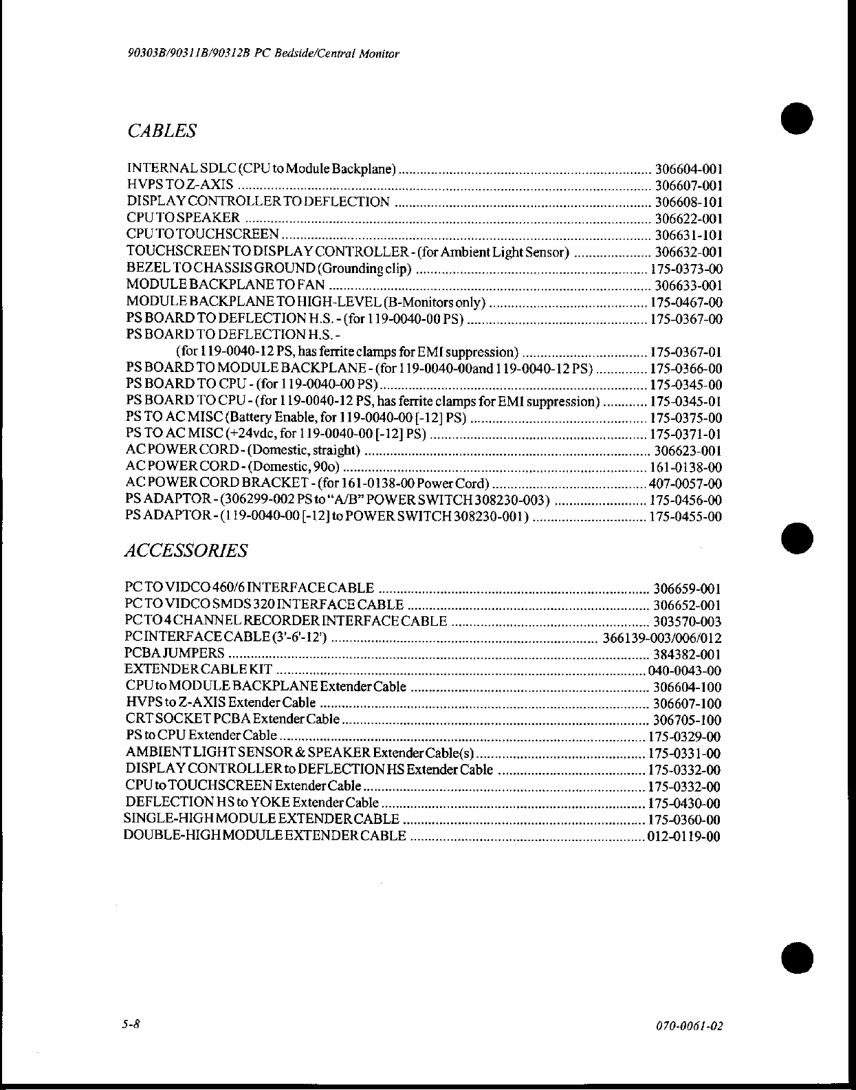
90303B/90311B/90312B
CABLES
PC
Bedside/Central
Monitor
INTERNAL
HVPSTOZ-AXİS
DISPLAY
CPUTOSPEAKER
SDLC
(CPU
CONTROLL
..............
to
Module
Backplane)...
onoho
onto
CPUTOTOUCHSCREEN.…
TOUCHSCREEN
BEZEL
MODULE
MODULE
PS
PS
PS
PSBOARDTOCPU-(f0r119-0040-00PS)......................................
PS
PS
PS
ACPOWER
ACPOWERCORD-
AC
PS
PS
ACCESSORIES
TOCHASSIS
BOARD
BOARD
(for
BOARD
BOARD
TO
AC
TO
AC
POWER
ADAPTOR-
ADAPTOR--
TODISPLAY
BACKPLANE
BACKPLANE
TO
DEFLECTION
TO
DEFLECTION
119-0040-12
TO
MODULE
TO
CPU - (for
MISC
(Battery
MISC
(+24vdc,
CORD-
CORD
(Domestic,
(Domestic,
BRACKET - (for
(306299-002
(1
19-0040-00
CONTROLLER - (for
GROUND
(Grounding
TO
FAN
TO
HIGH-LEVEL
HS. - (for
HLS.
-
PS, has
Enable,
ferrite
BACKPLANE - (for 1 19-0040-00and 1 19-0
119-0040-12
for
for
119-0040-00
straight)
900)
PS
to
“A/B"
[-12]
to
clip)
(B-Monitors
119-0040-00
clamps
PS,
has
ferrite
119-0040-00
[-12]
…
.........
161-0138-00
POWER
POWER
SWITCH
...
for
EMI
[-12]
PS)
Power
SWITCH
Ambient
only)
PS)
suppression)
clamps
PS)
..
Cord)
308230-003)
308230-001)
Light
Sensor)
....
..
for
EMI
suppression)
.............
.........
..
306604-001
306607-001
-
.
.
175-0373-00
306633-001
…
175-0467-00
…
175-0367-00
....175-0367-01
.175-0366-00
.175-0345-00
............
175-0345-01
…
173-0375-00
.175-0371-01
..
306623-001
…
161-0138-00
....407-0057-00
.175-0456-00
175-0455-00
PCTO
VIDCO
PCTOVIDCOSMDS
PCTO4CHANNEL
PCINTERFACE
PCBAJUMPERS....................................
EXTENDER CABLEKIT
CPUto
HVPStoZ-AXIS
CRT
PS
AMBIENT
DISPLAY
CPU
DEFLECTION
SINGLE-HIGH
DOUBLE-HIGH
MODULE
SOCKET
to
CPU
to
TOUCHSCREEN
460/6
INTERFACE
320INTERFACECABLE
RECORDER
CABLE
ExtenderCable..........
PCBA
Extender
LIGHT
CONTROLLER
HS
MODULE
MODULE
(3'-6'-12')
..
BACKPLANE
Cable
SENSOR & SPEAKER
to
Extender
......................
to
DEFLECTION
Extender
YOKE
Extender
EXTENDER
EXTENDER
CABLE
INTERFACE
Extender
Cable..
Cable
Cable
Cable
Extender
.......
CABL)
CABLE
..
CABLE
emma
.
HS
Extender
..
Cable(s)...........
....
....
Cable
306659-001
..
306652-001
…-
303370-003
.
366139-003/006/012
amenna
.
384382-001
.040-0043-00
Ni
..
306607-100
«+.
175-0329-00
…
175-0331-00
175-0332-00
175-0332-00
175-0430-00
175-0360-00
…
012-01
19-00
5-8
070-0061-02
 Loading...