

Page 1

Ambulatory Blood Pressure
Report Generator
90239A
Operations Manual
070-0399-03 Rev. E
Page 2

Copyright 2003 Datex-Ohmeda, Inc.
C
All rights reserved. Contents of this publication may not be reproduced in any form without the written permission of Datex-Ohmeda,
Inc. Products of Spacelabs Medical, a Division of Instrumentarium, Datex-Ohmeda, Inc. (“Spacelabs Medical”) are covered by U.S.
and foreign patents and/or pending patents. Printed in U.S.A. Specifications and price change privileges are reserved.
Spacelabs Medical considers itself responsible for the effects on safety, reliability and performance of the equipment only if:
• assembly operations, re-adjustments, modifications or repairs are carried out by persons authorized by Spacelabs
Medical, and
• the electrical installation of the relevant room complies with the requirements of the standard in force, and
• the equipment is used in accordance with the operations manual.
Spacelabs Medical will make available, on request, such circuit diagrams, component part lists, descriptions, calibration instructions
or other information which will assist appropriately qualified technical personnel to repair those parts of the equipment which are
classified by Spacelabs Medical as field repairable.
Spacelabs Medical is committed to providing comprehensive customer support beginning with your initial inquiry through purchase,
training, and service for the life of your Spacelabs Medical equipment.
CORPORATE OFFICES
U.S.A.
Spacelabs Medical
5150 220th Ave SE
Issaquah, WA 98029
Telephone: 425-657-7200
Telephone: 800-345-2700
Fax: 425-657-7212
AUSTRALIA
Datex-Ohmeda Pty Ltd
Unit 1, 149 Arthur Street
Locked Bag 356
Homebush, NSW 2140
Telephone: 61-2-9735-7222
Fax: 61-2-9764-2354
AUSTRIA & BELGIUM
Meda n.v.
Oeyvaersbosch 12
B-2630 Aartselaar
Belgium
Telephone: 32-3-870-1111
Fax: 32-3-870-1112
CANADA
Datex-Ohmeda Inc.
1093 Meyerside Drive, Unit 2
Mississauga, Ontario L5T 1J6
Telephone: 905-565-8572
Fax: 905-565-8592
CHINA
Datex-Ohmeda Pte Ltd
Shanghai Representative Office
Room 2509 Lippo Plaza
No. 222 Huaihai Road (M)
Shanghai 200021
Telephone: 86-21-5382-5657
Fax: 86-21-5382-1691
FRANCE
Spacelabs Medical
ZAC de Sans-Souci
1211 Chemin de la Bruyére
69760 Limonest
Telephone: 33 4 78 666 210
Fax: 33 4 78 432 658
GERMANY
Datex-Ohmeda GmbH
Dr. -Alfred-Herrhausen-Allee 24
D-47228 Duisburg
Telephone: 49-2065-691-0
Fax: 49-2065-691-236
HONG KONG
Spacelabs Medical Limited
Suite 901 Tower 1
China Hong Kong City
33 Canton Road, Tsimshatsui
Kowloon
Telephone: 852-2376-1370
Fax: 852-2376-2502
INDIA
Datex-Ohmeda India Pvt. Ltd.
International Trade Tower
S 3 Level, Block E
Nehru Place
New Delhi 110019
Telephone: 91-11-621-6060
Fax: 91-11-621-3003
ITALY
Datex-Ohmeda S.p.A.
Via Cassanese, 100
20090 Segrate (MI)
Telephone: 39-02-216-931
Fax: 39-02-2692-6226
SPAIN
Datex-Ohmeda SL
Manuel Tovar, 26
28034 Madrid
Telephone: 34-91-3342600
Fax: 34-91-3581284
TAI WAN
Datex-Ohmeda Pte Ltd
Taiwan Representative Office
2/FI No. 85 Sec. 2
Chien-Kuo N. RD.
Telephone: 8862-2515-0457
Fax: 8862-2501-9136
THE NETHERLANDS
Datex-Ohmeda B.V.
De Wel 18 3871 MV
Hoevelaken
Telephone: 31-33-25-41-222
Fax: 31-33-25-41-223
Authorized EC Representative
UNITED KINGDOM
Datex-Ohmeda Ltd
71 Great North Road, Hatfield
Herts AL9 5EN
Telephone: 44-1707-263-570
Fax: 44-1707-260-065
AUTION:
• US Federal law restricts the devices documented herein to sale by, or on the order of, a
physician.
Page 3

Contents
Chapter Page
Report Generator
Overview . . . . . . . . . . . . . . . . . . . . . . . . . . . . . . . . . . . . . . . . . . . . . . . . . . . . . . . . . . . . . . . .1-1
Setup . . . . . . . . . . . . . . . . . . . . . . . . . . . . . . . . . . . . . . . . . . . . . . . . . . . . . . . . . . . . . . . . . . .1-4
Report Generator Operation . . . . . . . . . . . . . . . . . . . . . . . . . . . . . . . . . . . . . . . . . . . . . . . . .1-9
Routine Maintenance . . . . . . . . . . . . . . . . . . . . . . . . . . . . . . . . . . . . . . . . . . . . . . . . . . . . .1-12
Sample Printouts. . . . . . . . . . . . . . . . . . . . . . . . . . . . . . . . . . . . . . . . . . . . . . . . . . . . . . . . .1-13
Symbols
i
Page 4

Page 5

Report Generator
Contents
Overview. . . . . . . . . . . . . . . . . . . . . . . . . . . . . . . . . . . . . . . . . . . . . . . . . . . . . . . . . . . . . . . . . . . . . . 1
Setup . . . . . . . . . . . . . . . . . . . . . . . . . . . . . . . . . . . . . . . . . . . . . . . . . . . . . . . . . . . . . . . . . . . . . . . . 4
Report Generator Operation. . . . . . . . . . . . . . . . . . . . . . . . . . . . . . . . . . . . . . . . . . . . . . . . . . . . . . . 9
Routine Maintenance . . . . . . . . . . . . . . . . . . . . . . . . . . . . . . . . . . . . . . . . . . . . . . . . . . . . . . . . . . . 12
Sample Printouts . . . . . . . . . . . . . . . . . . . . . . . . . . . . . . . . . . . . . . . . . . . . . . . . . . . . . . . . . . . . . . 13
Overview
Report Generator
The 90239A ABP Report Generator works in conjunction with a Spacelabs Medical ambulatory
blood pressure (ABP) monitor (90207, 90217). It receives patient data collected by the monitor,
processes that data, and prints it out in graphical and/or tabular formats on either its small built-in
printer or an optional external printer.
The report generator can be configured by the user via a simple-to-use menu system. You can step
through the entire menu and change every setting, or you can quickly access just those parameters
that you wish to alter. The menu items are self-explanatory, requiring you simply to enter a numeric
value.
The report generator software can be upgraded via a ROM card that fits into a card slot below the
control panel. Contact your sales representative for details.
Data Card Option
The Data Card option (P/N 040-0549-00) permits multiple blood pressure reports to be stored to and
printed from a data card that inserts into the card slot under the control panel (refer to Figure 1-1,
).
item
When you connect the serial port on the report generator to a serial port on a PC running 90219-02
or 90219-03 ABP Analysis software (version 4.00.00 or higher) the report generator becomes a data
card reader. Patient data can then be transferred from the data card to the computer’s memory and
printed.
External Printer Option
90239A Report Generators with software versions 1.13.04 and higher can print reports and
messages on an external printer connected to the 25-pin connector located on the back panel (refer
to Figure 1-2, item ). This configuration requires use of a parallel printer cable and, if the Data
Card option is used, a data key must be installed between the 90239A rear panel connector and the
printer cable. (Refer to Figure 1-5.)
1-1
Page 6
Ambulatory Blood Pressure Report Generator
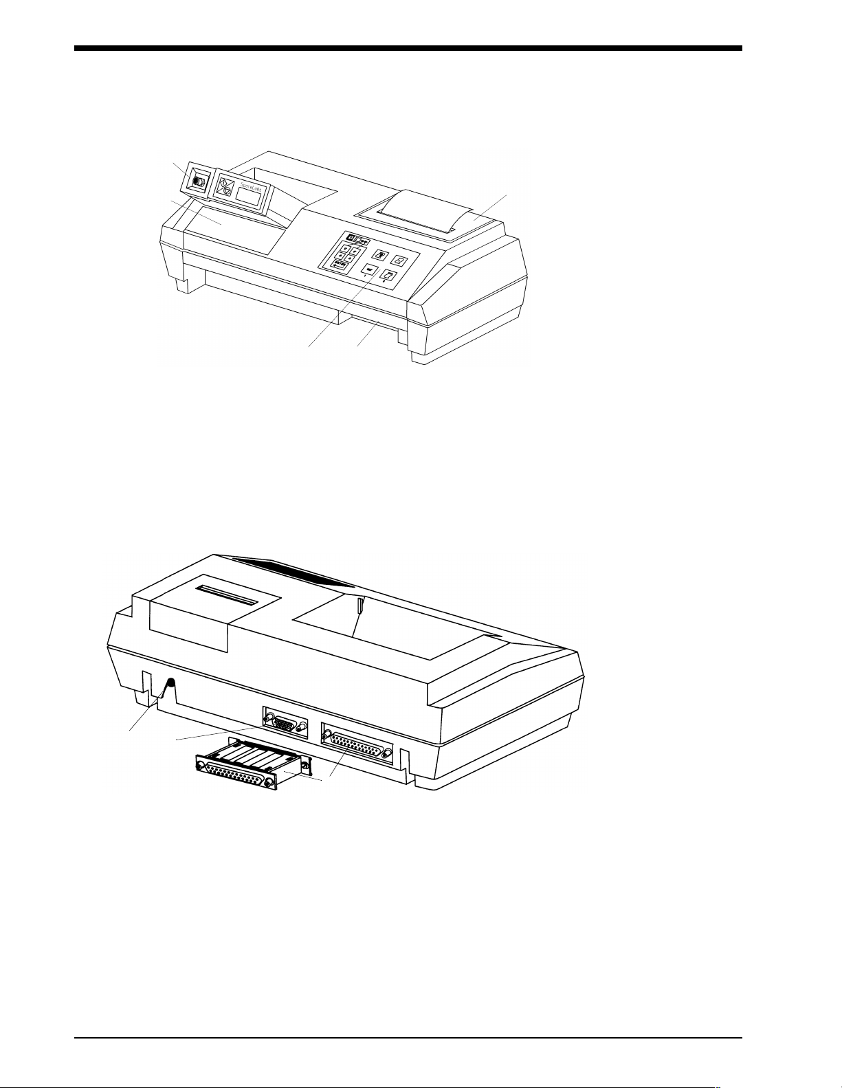
Figure 1-1: 90239A ABP Report Generator
ABP monitor placed in chute of 90239A Report Generator for data transfer
Label providing definitions for menu items
User control panel
Card slot for Data Card option
Removable plastic cover to access printer paper
Figure 1-2: 90239A rear view
Input connector for power adapter, 9 VDC, 800 ma (110 V: P/N 655-0636-00;
230 V: P/N 119-0125-00)
Serial port for connection to a PC containing 90219-02 or 90219-03 ABP Analysis software
Data key and data key/external printer port
Attaching a data key to this connector enables the data card option and adds menu items for
printing report summaries and selecting patient data for printing.
1-2
Page 7
Report Generator
!
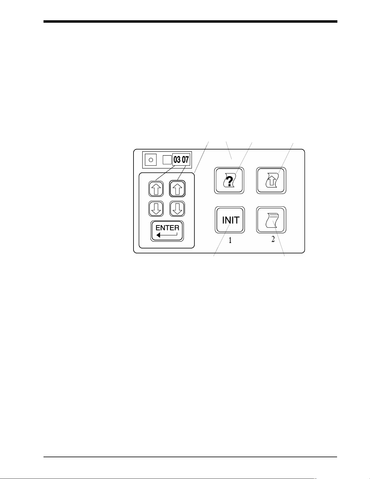
Control Panel Keys
The control panel keys are functionally divided into a group of five keys on the left and a group of
four keys on the right (refer to Figure 1-3 below).
• The ABP monitor must be switched ON and placed in the report generator’s chute
before most control panel keys will function. Otherwise, an error message will
print.
INITIALIZE
Figure 1-3: Control Panel keys
The group of five keys on the left provides printing and menu configuring functions. Refer to
Printing the Configuration Menu on page 1-8 and Configuration Menu Setup on page 1-6 for
details.
PRINT HELP
LINEFEED
PRINT REPORT
The four keys on the right are as follows: Print Help, Linefeed, Initialize, and Print Report.
PRINT HELP
Press this key once to print brief definitions of the four keys on the right. When printing is complete,
press it again to print brief definitions of the five keys on the left. This key also prints specified menu
items (refer to Changing Menu Configurations on page 1-8). Press this key during printing to abort
printing the key definitions.
LINEFEED
This key feeds one line of paper and moves the print head across the print area each time it is
pushed. This is the only key that is functional when an ABP monitor is not in the chute. If the paper
jams while printing, clear the jam and then press this key to clear the error from memory and stop
the ABP monitor from beeping. (Beeping indicates an error condition.)
1-3
Page 8

Ambulatory Blood Pressure Report Generator
!
INITIALIZE
Press this key to erase any patient data stored in the ABP monitor and to load current ABP monitor
settings from the menu (refer to Initializing the ABP Monitor on page 1-9).
PRINT REPORT
Press this key to print a patient data report. Press it again during printing to abort the print process
(refer to Printing Patient Data on page 1-10 for more information). With the Data Card option
installed, this key copies patient data from the ABP monitor onto a data card inserted into the card
slot rather than printing the report on paper. Remove the data card to physically print a report.
Setup
Paper Loading and Clearing (internal printer)
CAUTION:
• Use only Spacelabs Medical thermal paper in the printer (P/N 006-0210-02).
The print mechanism may be permanently damaged if other brands of paper
are used.
1. Ensure that the print head is positioned at the far left. If not, apply electrical power to the report
generator. The print head will now make one or more passes across the print area. When it
holds its position against the left side for several seconds, disconnect electrical power.
2. Remove the plastic cover over the cradle for the thermal paper and orient the roll so that the
paper feeds from the bottom. Fold the left corner back so that the right corner forms a point
(Figure 1-4).
Figure 1-4: Loading the paper
3. Feed the point of the thermal paper through the slot in the bottom of the paper roll cradle until
the point emerges up in the print area. Use tweezers to help pull the paper through until the
entire fold clears the print head.
4. Thread the point through the slot in the plastic cover for the paper cradle and replace the
plastic cover. This cover MUST be in place during printing.
• If an external printer is used, consult its operator’s manual for paper loading
instructions.
1-4
Page 9
Report Generator
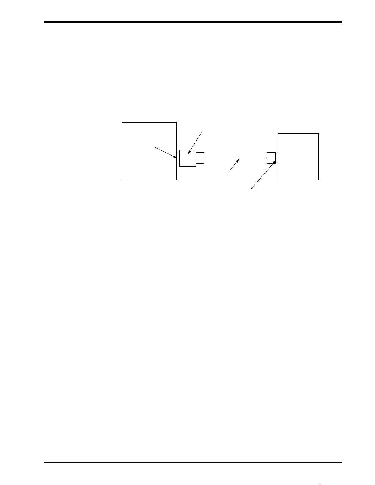
External Printer Configuration
Beginning with software version 1.13.04, the 90239A can print reports and messages on an external
printer connected to the 25-pin connector located on the back of the report generator. This
configuration requires use of a centronics parallel printer cable and, if the Data Card option is used,
a data key installed between the 90239A rear panel connector and printer cable. Refer to Figure 1-5
below.
data key
(if Data Card used)
25-pin rear panel
connector
parallel printer
cable
90239A
printer centronics
connector
External
Printer
Figure 1-5: External printer configuration
Either of these two printers can be used:
• Okidata Microline 320 (or 100% compatible)
• IBM ProPrinter (or 100% compatible)
Two additional menu items now appear on the 90239A to support use of an external printer.
Menu Item
37 00 Messages printed on internal printer.
38 01 An Okidata is connected to the 90239A.
Selections
Available
01 Messages printed on external printer.
02 An IBM ProPrinter is connected to the 90239A.
Description
1-5
Page 10

Ambulatory Blood Pressure Report Generator
!
Configuration Menu Setup
The report generator’s configuration menu allows you to define certain modes of its operation
according to individual requirements. Each menu item is identified on a front panel label (refer to
Figure 1-1, item ). To select a menu item, press the left UP or DOWN arrow key on the report
generator control panel until the desired two-digit menu item appears as the left pair of digits in the
ABP monitor display.
The right pair of digits on the monitor display reflects the current setting for the menu item; press the
right UP or DOWN arrow key on the control panel to display the desired value, then press ENTER to
select that value.
• When a YES or NO response is required, 00 = NO and 01 = YES.
Menu Functions
Item # Function (for software versions 1.17.00 or higher) Default
01 Press ENTER to print a description of all menu items and their current
settings.
02 Specify start of waking hours. 06:00
03 Specify start of sleeping hours. 23:00
04 Specify time interval between each measurement during waking
hours.
05 Is a tone to sound 5 seconds before each programmed reading taken
during waking hours (yes or no)?
06 Specify the time interval between each measurement during sleeping
hours.
07 Is a reading to be displayed on the monitor after each measurement
(yes or no)?
08 Is cuff pressure to be displayed during each measurement
(yes or no)?
09 Specify how time is to be displayed (A.M./P.M. or 24-hour format) on
the monitor.
10-14 Specify current hour, minute, year, month, and day, respectively. ---
15 Specify the maximum allowable cuff pressure (displayed on monitor
as value divided by 10).
---
20 minutes
Yes
60 minutes
Yes
Yes
24
290
16 Are summary tables to be printed on report (yes or no)? Yes
17 Are raw data tables to be printed on report (yes or no)?
Refer to Sample Printouts on page 1-13.
18 Are hourly average blood pressure graphs to be printed on report
(yes or no)?
Refer to Sample Printouts on page 1-13.
1-6
Yes
Yes
Page 11

Report Generator
Item # Function (for software versions 1.17.00 or higher) Default
19 Are raw blood pressure data graphs to be printed on reports
(yes or no)?
Refer to Sample Printouts on page 1-13.
20 Are heart rate graphs to be printed on reports (yes or no)?
Refer to Sample Printouts on page 1-13.
21 Specify the waking hours systolic statistical boundary used to
compute the statistical summaries (displayed as value minus 100).
22 Specify the waking hours diastolic statistical boundary used to
compute the statistical summaries.
23 Specify the sleep hours systolic statistical boundary (displayed on
monitor as value minus 100).
24 Specify the sleep hours diastolic statistical boundary. 80
25 Are readings that violate the auto edit limits to be removed
(yes or no)?
26 Specify the auto edit limit for maximum systolic (displayed on monitor
as value divided by 10).
27 Specify the auto edit limit for minimum systolic (displayed on monitor
as value divided by 10).
28 Specify the auto edit limit for maximum diastolic (displayed on monitor
as value divided by 10).
Yes
Yes
140
90
120
Yes
260
70
150
29 Specify the auto edit limit for minimum diastolic (displayed on monitor
as value divided by 10).
30 Specify the auto edit limit for maximum pulse pressure (displayed on
monitor as value divided by 10).
31 Specify the auto edit limit for minimum pulse pressure (displayed on
the monitor as value divided by 10).
32 Specify the auto edit limit for maximum heart rate (displayed on
monitor as value divided by 10).
33 Specify the auto edit limit for minimum heart rate (displayed on
monitor as value divided by 10). Default: 40
34 Specify the language (1 = English, 2 = French, 3 = German,
4 = Italian, 5 = Spanish).
35 Should graphs be automatically scaled to match data values
(yes or no)?
36 Press ENTER to reset all menu items to factory default settings. ---
37 Should messages be printed on an external printer (yes or no)? No
38 Specify the external printer type (01 = Okidata, 02 = IBM). 01
39 Press ENTER to print a summary of the reports stored on the data
card. (Optional Data Card must be installed.)
40
150
20
200
40
---
Yes
---
1-7
Page 12

Ambulatory Blood Pressure Report Generator
!
Item # Function (for software versions 1.17.00 or higher) Default
40 Select item value 00 and press ENTER to print a list of currently
queued reports. (Optional Data Card must be installed.)
41 Press ENTER to format the data card. (Optional Data Card must be
installed.)
Changing Menu Configurations
1. Turn the ABP monitor power ON and place it in the report generator chute. Press the left UP
or DOWN arrow key until the desired menu item number is displayed on the monitor. (To print
the menu item and its current setting, press the PRINT HELP key.)
2. Press the right UP or DOWN arrow key until the desired value is displayed on the right side of
the ABP monitor. When a YES or NO response is required, 00 = NO and 01 = YES.
3. Press ENTER.
Menu Configuration Example
Menu item 02 allows you to specify the time the patient normally wakes up. Assume that you want to
change this wake-up time from the current setting of 06:00 (meaning 6:00 AM) to 08:00.
1. Ensure that the ABP monitor power switch is ON and that the monitor is placed in the report
generator chute. Connect the report generator to external power.
2. After the ABP monitor shows a steady “0000,” press the left UP arrow key on the report
generator control panel until “0206” appears (where 02 is the menu item and 06 represents
6:00 A.M.).
---
---
3. Press the right UP arrow key on the control panel until “08” is displayed in the right half of the
ABP monitor (the new value will start flashing). If you hold the arrow key down, you will see
that the numbers scroll to 23 (denoting 11:00 P.M.) and then start over at 00. (The menu is
always in a 24-hour format.)
4. Press ENTER to change the waking hour to the displayed value. The new value will stop
flashing when it has been saved to memory.
• The ABP monitor will continue to use the previous wake-up setting of 6:00 A.M. if
the ENTER key is not pressed.
Printing the Configuration Menu
A printout of current menu settings is useful when configuring the report generator. To print a copy of
this menu:
1. Ensure that the ABP monitor has fresh batteries installed and the report generator has paper
loaded and is connected to external power.
2. Turn the ABP monitor power switch ON.
3. A four-digit number will be displayed on the ABP monitor, and then a time value will appear
with a flashing colon (you can later set the correct time via the menu).
4. Place the ABP monitor in the chute. It will display “9999” and then quickly run through a series
of numbers. The display will then show a steady “0000.”
1-8
Page 13

Report Generator
!
!
5. Press the left UP arrow key once. The ABP monitor should now display “0100.” If the display
shows anything other than 0100, press the left UP or DOWN arrow key until the ABP monitor
displays 0100.
6. Press ENTER. The report generator will now print out the full menu along with the current
settings (if this is the first time to print the menu, it will reflect factory default settings). This
process takes several minutes.
Keep this menu printout for future reference.
Report Generator Operation
Initializing the ABP Monitor
Initializing the ABP monitor erases all stored patient data and loads any new monitor-related menu
changes.
To initialize the ABP monitor:
1. Turn the ABP monitor power switch ON and place the monitor in the report generator chute.
Menu changes can now be made (refer to Configuration Menu Setup on page 1-6).
2. Press the INIT key.
The paper automatically advances one linefeed and the report generator indicates a successful
initialization by printing a “Ready for use” message.
If you try to initialize the ABP monitor before its stored data has been printed or stored to a data
card, the report generator prints the message “Monitor contains unprocessed data. This data will be
lost if initialization continues!” When this happens, either:
• Press the INIT key again to continue initialization (the un-printed data will be erased), or
• Press ENTER to abort the initialization process. In this case, the report generator prints
“Monitor initialization aborted.”
Copying ABP Monitor Data to a Data Card
To copy patient data from an ABP monitor to a data card (optional):
1. Insert a data card into the card slot on the front of the ABP Report Generator (refer to Figure
1-1, item
2. Turn the ABP monitor power switch ON and place the monitor in the report generator chute.
3. Wait until the ABP monitor display reads “0000,” then press the PRINT REPORT key. The
report generator will print “Reading monitor.” The patient report will now be copied to the data
card and receive the next sequential number.
). Ensure that the data key is also connected to the back of the report generator.
•If either the data card or data key is not installed, patient data will print out on the
report generator instead of being copied to the data card.
• To abort copying the data to the data card, press the PRINT REPORT key a
second time.
To erase patient data in the ABP monitor, refer to Initializing the ABP Monitor above.
1-9
Page 14

Ambulatory Blood Pressure Report Generator
!
!
!
Printing Patient Data
• When a red stripe appears on the print paper, it indicates that 5 to 8 feet (1.3m to
2.4m) of paper remain on the roll. Do not start printing a report when this stripe
appears. The report generator will attempt to continue printing even after it has run
out of paper. Cut or tear off the paper from the roll. Pull the paper strip remaining
in the print unit out in the same direction as normal paper movement and load a
fresh roll of paper.
Patient data can be printed either directly from the ABP monitor or from a data card. Patient data
prints in the order shown below (graphs and/or tables may not print depending upon your menu
selections):
1. Patient demographic header and technical data.
2. Data summary tables (total, daytime, and nighttime).
3. Hourly average data table (one table for each 24 hours).
4. Hourly average pressure graph (one graph for each 24 hours).
5. Hourly average heart rate graph (one graph for each 24 hours).
6. Raw data table (one table for each 24 hours).
7. Edited data table (one table for each 24 hours).
8. Raw data pressure graph (one graph for each 24 hours).
9. Raw data heart rate graph (one graph for each 24 hours).
Data that was obtained when the patient manually started a reading via the ABP monitor’s
START/STOP switch will be tagged with an “m” (for manual reading).
Data that was obtained on a second try after the ABP monitor failed to obtain a valid reading the first
time will be tagged with an “r” (for retry).
Data that was obtained at pre-programmed times via menu settings will be un-tagged.
To Print Patient Data from the ABP Monitor
1. Turn the ABP monitor power switch ON and place the monitor in the report generator chute.
2. Wait until the ABP monitor display reads “0000,” then press the PRINT REPORT key. The
report generator will print “Reading monitor.”
• If the ABP monitor contains no data, the message “Monitor contains no readings”
prints.
3. The patient data report will now print in accordance with the current menu settings on the
report generator.
• To abort printing, press the PRINT REPORT key a second time.
The ABP monitor retains patient data until it is initialized (refer to Initializing the ABP Monitor on
page 1-9).
1-10
Page 15

Report Generator
!
To Print Patient Reports from a Data Card
1. Insert the data card into the report generator card slot.
2. Each patient report that is copied onto a data card is numbered sequentially. This number is
used to select each report for printing. If the sequential number of the report to be printed is
already known, move ahead to step 3. If not, use the left UP or DOWN arrow key to select
menu item 39, and press ENTER. This prints a list of the patient reports on the data card along
with their sequential numbers.
3. Select menu item 40 and use the right UP or DOWN arrow key to select the sequential number
of the first patient data report to be printed. Press ENTER to transfer this number to the print
queue, which is a list of the patient data reports to be printed. Additional patient data reports
can be added to the print queue by selecting their numbers and pressing ENTER.
4. To verify the report numbers in the print queue prior to printing, use the left UP or DOWN arrow
key to select menu item 40, then use the right UP or DOWN arrow key to select 00. Press
ENTER to print a list of all report numbers that are in the queue ready for printing.
5. To print all the patient reports in the print queue, press the PRINT REPORT key.
• To abort printing patient, press the PRINT REPORT key a second time.
Printing and Copying a Patient Report
To print a patient report prior to copying it to a data card:
1. Press the PRINT REPORT key without inserting the data card.
2. After the data has been printed, insert the data card into the card slot (the data key must also
be connected), and press the PRINT REPORT key.
Reverse steps 1 and 2 if patient data is to be copied to a data card first and then printed.
1-11
Page 16

Ambulatory Blood Pressure Report Generator
Correcting Printer Paper Problems
The ABP monitor beeps continuously if an error occurs during printing, such as torn paper in the
print area or the paper not feeding freely through the paper-feed mechanism. To clear the problem,
cut off the paper roll and pull the remaining paper strip in the direction of normal paper movement.
Reload fresh paper and press the LINEFEED key on the control panel to clear the error from
memory.
CAUTION:
• Do NOT pull the paper backwards through the printer. Reversing the normal
direction of paper flow may permanently damage the paper-feed
mechanism. Pull the remaining paper out only in the direction indicated in
Figure 1-6.
Figure 1-6: Clearing paper jams
Routine Maintenance
The following maintenance activities should be done on an as-needed basis:
• Wipe all external surfaces with a damp cloth. Ensure that no dust, lint, etc., obstructs the
infrared window in the bottom of the chute.
• Remove the printer cover and vacuum out accumulated dirt and paper fiber from the print
head area. Use tweezers to remove any paper scraps.
Performance Verification
Report Generator
The report generator performs a self-test each time it is connected to power. Following a successful
self-test, the following information is printed:
• Model name (ABP Report Generator).
• Software version (for the report generator).
• Year of copyright.
• Software version (for the ABP monitor).
• Current date and time (programmable via the menu).
1-12
Page 17

Report Generator
!
!
!
ABP Monitor
The ABP monitor performs a self-test each time its power switch is turned ON. Following a
successful self-test, the monitor displays its software version number (0209 or a similar value) and
then displays the current time. If the ABP monitor is inserted into the chute of the report generator at
this time, it flashes a series of numbers and then displays “0000.”
• If the ABP monitor maintains a display of “9999,” the report generator is not
powered up.
An unsuccessful self-test will display “EC25,” indicating that the ABP monitor’s software program
has been corrupted. Place the ABP monitor in the chute, and the report generator will reload the
software program. When the reloading process is complete, the ABP monitor will display “0000” and
the report generator prints the message “Monitor software successfully installed in monitor.”
• Event Code (EC) numbers are defined in your ABP monitor manual.
Sample Printouts
The following pages show examples of internal and external printouts.
• For explanations of Event Code (EC) numbers, refer to your ABP monitor’s
manual.
1-13
Page 18

Ambulatory Blood Pressure Report Generator
Internal Printer Samples
1-14
Page 19

Internal Printer Samples (continued)
Report Generator
1-15
Page 20

Ambulatory Blood Pressure Report Generator
External Printer Samples
1-16
Page 21

External Printer Samples (continued)
New Graphics to be added
Report Generator
1-17
Page 22

Ambulatory Blood Pressure Report Generator
External Printer Samples (continued)
New Graphics to be added
1-18
Page 23

External Printer Samples (continued)
Report Generator
1-19
Page 24

Ambulatory Blood Pressure Report Generator
External Printer Samples (continued)
1-20
Page 25

External Printer Samples (continued)
Report Generator
1-21
Page 26

Ambulatory Blood Pressure Report Generator
External Printer Samples (continued)
1-22
Page 27

Symbols
The following list of international and safety symbols describes all symbols used on Spacelabs Medical products. No one
product contains every symbol.
Symbol Description Symbol Description
RECORD
UCW or Ultraview 1700
HELP Key
UCW or Ultraview 1700
SPECIAL FUNCTIONS Key
UCW or Ultraview 1700
RECORD Key
UCW or Ultraview 1700
NORMAL SCREEN Key
UCW or Ultraview 1700
Keyboard Connection
OFF — Power Disconnection from
Mains
Off Position for Push button Power
Switch
RESET
TOnE
ALM SUSPEND
UCW or Ultraview 1700
MONITOR SETUP Key
UCW or Ultraview 1700
ALARMS Key
UCW or Ultraview 1700
PREVIOUS MENU Key
UCW or Ultraview 1700 mouse
connection
ON — Power Connection to Mains
On Position for Push button Power
Switch
STOP or CANCEL Key
CONTINUE Key START/STOP Key
START/STOP START (NIBP) Key
On Direction ON/OFF
Television; Video Display Recycle
Protective Earth Ground Functional Earth Ground
2-1
Page 28

Ambulatory Blood Pressure Report Generator
Symbol Description Symbol Description
ON — Part of the Instrument Only OFF — Part of the Instrument Only
Partial ON/OFF STAND-BY Key
All batteries should be disposed of
properly to protect the environment.
Lithium batteries should be fully
discharged before disposal. Batteries
such as lead-acid (Pb) and nickelcadmium (Ni-Cd) must be recycled.
Please follow your internal procedures
and or local (provincial) laws regarding
disposal or recycling.
Caution - hazardous voltages. To reduce
risk of electric shock, do not remove the
cover or back. Refer servicing to a
qualified service personnel (U.S.A.).
DANGER - High Voltage (International)
PAUSE or INTERRUPT Slow Run
Replace Fuse Only as Marked Fuse
Power supply jack polarity.
(+ / - Signs May be Reversed)
Battery
Replace only with the appropriate
battery.
Alternating Current Direct Current
Both Direct and Alternating Current AC/DC Input
AHz
Amperes Hertz
Equipotentiality Terminal
Replace only with the appropriate
battery.
(+ / - Signs May be Reversed)
VW
2-2
Volts Watts
Temporary Shut Off of Alarm Tone or
Screen Indicators
Alarm
Page 29

Symbol Description Symbol Description
ENTER Key PRINT REPORT Key
Symbols
!
Service Manual for Description
Attention - Consult Operations or
Risk of Explosion if Used in the
Presence of Flammable Anesthetics
Indicator — Remote control Indicator — Local Control
1
2
3
Return Unit to Monitor Mode Indicator — Out of Paper
Activate Recorder for Graphics Recorder Paper
Indoor Use Only Auto Mode (NIBP)
Output No Output (Terminated)
Data Input/Output HELP (Explain Prior Screen) Key
?
Clock/Time Setting Key Input/Output
1
2
3
1
2
3
1
2
1
3
2
3
Monitor Setup
Select Program Options
B
Access Special Function Menu Normal Screen
Return to Prior Menu TREND/TIMER Key
Gas Exhaust
1
2
3
A
Set Initial Conditions Menu
Electrocardiograph or
Defibrillator Synchronization
2-3
Page 30

Ambulatory Blood Pressure Report Generator
Symbol Description Symbol Description
IEC 601-1 Type BF equipment. The unit
displaying this symbol contains an F-
Arterial Pulse
IEC 601-1 Type BF equipment which is
defibrillator-proof. The unit displaying
this symbol contains an F-type isolated
(floating) patient-applied part which
contains an adequate degree of
protection against electric shock, and is
defibrillator-proof.
IEC 601-1 Type CF equipment. The unit
displaying this symbol contains an Ftype isolated (floating) patient-applied
part providing a high degree of
protection against electric shock, and is
defibrillator-proof.
type isolated (floating) patient-applied
part providing an adequate degree of
protection against electric shock.
IEC 601-1 Type CF equipment. The unit
displaying this symbol contains an Ftype isolated (floating) patient-applied
part providing a high degree of
protection against electric shock.
ETL Laboratory Approved
IEC 601-1 Type B equipment. The unit
displaying this symbol contains an
adequate degree of protection against
electric shock.
Keypad Enlarge, Zoom
Menu Keys Delete
Waveform/Parameter Keys PCMCIA Card
Keep Dry Fragile; handle with care
Foot Switch This Way Up
Environmental Shipping/Storage
Temperature Limitations
x
Canadian Standards Association
Approved
Environmental Shipping/Storage
Humidity Limitations
2-4
Page 31

Symbol Description Symbol Description
Open Padlock Closed Padlock
Down Arrow Up Arrow
Symbols
Event
Antenna
Network Connection Audio Output, Speaker
Remote Alarm; Nurse Alert Nurse Call
1 2
Serial Port 1 Serial Port 2
TEMP
temp
12,200 m
Temperature
Environmental Shipping/Storage
Altitude Limitations
External marker push button connection SDLC Port
Microphone Mermaid Connector
SDLC
2-5
Page 32

Ambulatory Blood Pressure Report Generator
!
Symbol Description Symbol Description
Note Video Output
Warning About Potential Danger to
Human Beings
Non-Invasive Blood Pressure (NIBP),
Neonate
Fetal Monitor Connection
RS232 (Digital)
Input Reset
Hard Drive Power Indicator LED
Caution About Potential Danger to
Equipment
Fetal Monitor Connection (Analog)
Physiological Monitor Connection
RS232 (Digital)
Activate Telemetry Recorder Omnidirectional Microphone
Battery Status Universal Serial Bus
Stand-by Low Battery
Gas Sampling Port Gas Return Port
2-6
Page 33

Symbol Description Symbol Description
Symbols
!
Operates on Non-Harmonized Radio
Frequencies in Europe
Happy Face Sad Face
Reset Power Indicator LED
Magnifying Glass Compression
File Cabinet List of Rooms
Service Message
Arrows Printer
2-7
Page 34

Ambulatory Blood Pressure Report Generator
Abbreviations used as symbols are shown below.
Symbol Description Symbol Description
1 - 32
ANT 1
ANT 2
CH
ch
CMV Controlled Mechanical Ventilation
DIA
dia
EEG
eeg
ESIS
Access Codes
1 Through 32
Diversity Antenna System 1
Diversity Antenna System 2
EEG, EMG, or ECG Channel
EEG Channels - CH1, CH2, CH3, CH4
EMG Channel - CH5
Diastolic
Electroencephalogram
Electrosurgical Interference
Suppression
AIR Air
Arr1
ArrNet2
O Centimeters of Water
cmH
2
C.O.
CO
co
ECG
ecg
EMG
emg
EXT External
Arrhythmia Net 1
Arrhythmia Net 2
Cardiac Output
Electrocardiogram
Electromyogram
FECG Fetal Electrocardiogram
GND
gnd
I:E Inspiration Expiration Ratio Multiview Multi-Lead Electrocardiogram
NIBP
nibp
O
2
PRESS
press
PRS
2-8
Patient Isolated Ground
Non-Invasive Blood Pressure N
Oxygen PEEP Positive End Expiratory Pressure
Pressure Pmin Minimum Inspiratory Pressure
FHR1
FHR2
HLO
hlo
O Nitrous Oxide
2
Fetal Heart Rate, Channel 1
Fetal Heart Rate, Channel 2
High-Level Output
Page 35

Symbol Description Symbol Description
Symbols
Ppeak Peak Inspiratory Pressure
SDLC Synchronous Data Link Control
SVO2
SvO2
O
Sv
2
T1
T2
T3
T4
VAC Vacuum connection
BirthNet, CVScan, Data Shuttle, FT1000, FT3000, Flexchart, Flexform, Flexport, Flextable, Flextools, Flexview, Global
Participant Index, Intesys, Multiview, Neoscan, PCIS, PCMS, PrintMaster, Quicknet, Sensorwatch, Spaceview, TRU-CAP,
TRU-CUFF, TRU-LINK, UCW, Ultralite, Ultraview, Ultraview Clinical Messenger, Uni-Pouch, Universal Flexport, Varitrend,
Web Source and WinDNA are trademarks of Datex-Ohmeda, Inc.
Other brands and product names are trademarks of their respective owners.
Mixed Venous Oxygen Saturation
Temperature 1
Temperature 2
Temperature 3
Temperature 4
RESP
resp
SPO2
SpO2
SpO
2
SaO
2
SYS
sys
UA Uterine Activity or Umbilical Artery
Respiration
Arterial Oxygen Saturation
as Measured by Pulse Oximetry
Systolic
2-9
 Loading...