

Page 1

Ambulatory Blood Pressure
Monitor
90207/90207Q
Service Manual
070-0189-02 Rev. F
more time to care
Page 2

© 2004 Spacelabs Medical, Inc.
All rights reserved. Contents of this publication may not be reproduced in any form without the written permission of Spacelabs
Medical. Products of Spacelabs Medical are covered by U.S. and foreign patents and/or pending patents. Printed in U.S.A.
Specifications and price change privileges are reserved.
Spacelabs Medical considers itself responsible for the effects on safety, reliability and performance of the equipment only if:
• assembly operations, re-adjustments, modifications or repairs are carried out by persons authorized by Spacelabs
Medical, and
• the electrical installation of the relevant room complies with the requirements of the standard in force, and
• the equipment is used in accordance with the operations manual.
Spacelabs Medical will make available, on request, such circuit diagrams, component part lists, descriptions, calibration instructions
or other information which will assist appropriately qualified technical personnel to repair those parts of the equipment which are
classified by Spacelabs Medical as field repairable.
Spacelabs Medical is committed to providing comprehensive customer support beginning with your initial inquiry through purchase,
training, and service for the life of your Spacelabs Medical equipment.
CORPORATE OFFICES
U.S.A.
Spacelabs Medical, Inc.
5150 220th Ave SE
Issaquah, WA 98029
Telephone: 425-657-7200
Telephone: 800-522-7025
Fax: 425-657-7212
Authorized EC Representative
UNITED KINGDOM
Spacelabs Limited
71 Great North Road, Hatfield
Herts AL9 5EN
Telephone: 44-1707-263-570
Fax: 44-1707-260-065
BirthNet, Data Shuttle, Flexport, Intesys Clinical Suite, Maternal Obstetrical Monitor, MOM, Mermaid, Multiview, PCIS, PCMS,
PrintMaster, Quicknet, Sensorwatch, TRU-CAP, TRU-CUFF, TRU-LINK, UCW, Ultralite, Ultraview, Ultraview Clinical Messenger,
Ultraview SL, Uni-Pouch, Universal Flexport, Varitrend and WinDNA are trademarks of Spacelabs Medical, Inc.
Other brands and product names are trademarks of their respective owners.
CAUTION:
US Federal law restricts the devices documented herein to sale by, or on the order
Rx
Only
of, a physician.
Page 3

Table of Contents
Contents
Introduction
Overview. . . . . . . . . . . . . . . . . . . . . . . . . . . . . . . . . . . . . . . . . . . . . . . . . . . . . . . . . . . . . . . . . . . . . . . . . . . . . . . . . 1-1
Description . . . . . . . . . . . . . . . . . . . . . . . . . . . . . . . . . . . . . . . . . . . . . . . . . . . . . . . . . . . . . . . . . . . . . . . . . . . . . . . 1-2
Front Panel . . . . . . . . . . . . . . . . . . . . . . . . . . . . . . . . . . . . . . . . . . . . . . . . . . . . . . . . . . . . . . . . . . . . . . . . . . . . . 1-2
Rear and Top View . . . . . . . . . . . . . . . . . . . . . . . . . . . . . . . . . . . . . . . . . . . . . . . . . . . . . . . . . . . . . . . . . . . . . . . 1-2
ABP System Options . . . . . . . . . . . . . . . . . . . . . . . . . . . . . . . . . . . . . . . . . . . . . . . . . . . . . . . . . . . . . . . . . . . . . . . 1-3
Installation
Hardware Requirements. . . . . . . . . . . . . . . . . . . . . . . . . . . . . . . . . . . . . . . . . . . . . . . . . . . . . . . . . . . . . . . . . . . . . 2-1
Setup Instructions for the 90121. . . . . . . . . . . . . . . . . . . . . . . . . . . . . . . . . . . . . . . . . . . . . . . . . . . . . . . . . . . . . . . 2-1
Setup Instructions for the 90219 and 92506. . . . . . . . . . . . . . . . . . . . . . . . . . . . . . . . . . . . . . . . . . . . . . . . . . . . . . 2-2
Installation . . . . . . . . . . . . . . . . . . . . . . . . . . . . . . . . . . . . . . . . . . . . . . . . . . . . . . . . . . . . . . . . . . . . . . . . . . . . . . . 2-2
Theory
Power Supplies. . . . . . . . . . . . . . . . . . . . . . . . . . . . . . . . . . . . . . . . . . . . . . . . . . . . . . . . . . . . . . . . . . . . . . . . . . . . 3-1
Power Converter . . . . . . . . . . . . . . . . . . . . . . . . . . . . . . . . . . . . . . . . . . . . . . . . . . . . . . . . . . . . . . . . . . . . . . . . . 3-1
Other Power Sources . . . . . . . . . . . . . . . . . . . . . . . . . . . . . . . . . . . . . . . . . . . . . . . . . . . . . . . . . . . . . . . . . . . . . 3-3
90207 Block Diagram . . . . . . . . . . . . . . . . . . . . . . . . . . . . . . . . . . . . . . . . . . . . . . . . . . . . . . . . . . . . . . . . . . . . . . . 3-4
Wake Up and Power Up Logic . . . . . . . . . . . . . . . . . . . . . . . . . . . . . . . . . . . . . . . . . . . . . . . . . . . . . . . . . . . . . . . . 3-5
START/STOP Button . . . . . . . . . . . . . . . . . . . . . . . . . . . . . . . . . . . . . . . . . . . . . . . . . . . . . . . . . . . . . . . . . . . . . 3-5
Power Switch . . . . . . . . . . . . . . . . . . . . . . . . . . . . . . . . . . . . . . . . . . . . . . . . . . . . . . . . . . . . . . . . . . . . . . . . . . . 3-5
Minute Pulse . . . . . . . . . . . . . . . . . . . . . . . . . . . . . . . . . . . . . . . . . . . . . . . . . . . . . . . . . . . . . . . . . . . . . . . . . . . . 3-6
Cable Connection . . . . . . . . . . . . . . . . . . . . . . . . . . . . . . . . . . . . . . . . . . . . . . . . . . . . . . . . . . . . . . . . . . . . . . . . 3-6
Second Pulse . . . . . . . . . . . . . . . . . . . . . . . . . . . . . . . . . . . . . . . . . . . . . . . . . . . . . . . . . . . . . . . . . . . . . . . . . . . 3-6
Watch Dog Timer . . . . . . . . . . . . . . . . . . . . . . . . . . . . . . . . . . . . . . . . . . . . . . . . . . . . . . . . . . . . . . . . . . . . . . . . 3-6
Fault Shutdown . . . . . . . . . . . . . . . . . . . . . . . . . . . . . . . . . . . . . . . . . . . . . . . . . . . . . . . . . . . . . . . . . . . . . . . . . . 3-7
Overpressure Detector . . . . . . . . . . . . . . . . . . . . . . . . . . . . . . . . . . . . . . . . . . . . . . . . . . . . . . . . . . . . . . . . . . . . 3-7
Pressure Amplifier . . . . . . . . . . . . . . . . . . . . . . . . . . . . . . . . . . . . . . . . . . . . . . . . . . . . . . . . . . . . . . . . . . . . . . . . . 3-7
Offset Adjust . . . . . . . . . . . . . . . . . . . . . . . . . . . . . . . . . . . . . . . . . . . . . . . . . . . . . . . . . . . . . . . . . . . . . . . . . . . . 3-7
Gain Adjust . . . . . . . . . . . . . . . . . . . . . . . . . . . . . . . . . . . . . . . . . . . . . . . . . . . . . . . . . . . . . . . . . . . . . . . . . . . . . 3-7
Pressure Amplifier Filters . . . . . . . . . . . . . . . . . . . . . . . . . . . . . . . . . . . . . . . . . . . . . . . . . . . . . . . . . . . . . . . . . . 3-7
Oscillometric Amplifier . . . . . . . . . . . . . . . . . . . . . . . . . . . . . . . . . . . . . . . . . . . . . . . . . . . . . . . . . . . . . . . . . . . . . . 3-8
Gain Switching . . . . . . . . . . . . . . . . . . . . . . . . . . . . . . . . . . . . . . . . . . . . . . . . . . . . . . . . . . . . . . . . . . . . . . . . . . 3-8
Offset and Limiting . . . . . . . . . . . . . . . . . . . . . . . . . . . . . . . . . . . . . . . . . . . . . . . . . . . . . . . . . . . . . . . . . . . . . . . 3-8
Digital Circuitry Display Board . . . . . . . . . . . . . . . . . . . . . . . . . . . . . . . . . . . . . . . . . . . . . . . . . . . . . . . . . . . . . . . . 3-8
Real-Time Clock . . . . . . . . . . . . . . . . . . . . . . . . . . . . . . . . . . . . . . . . . . . . . . . . . . . . . . . . . . . . . . . . . . . . . . . . . . . 3-8
RAM . . . . . . . . . . . . . . . . . . . . . . . . . . . . . . . . . . . . . . . . . . . . . . . . . . . . . . . . . . . . . . . . . . . . . . . . . . . . . . . . . . . . 3-8
Addressing and Control Lines . . . . . . . . . . . . . . . . . . . . . . . . . . . . . . . . . . . . . . . . . . . . . . . . . . . . . . . . . . . . . . . . 3-9
Communications RS-232 Connector . . . . . . . . . . . . . . . . . . . . . . . . . . . . . . . . . . . . . . . . . . . . . . . . . . . . . . . . . . . 3-9
Microprocessor . . . . . . . . . . . . . . . . . . . . . . . . . . . . . . . . . . . . . . . . . . . . . . . . . . . . . . . . . . . . . . . . . . . . . . . . . . . . 3-9
Maintenance
Cleaning . . . . . . . . . . . . . . . . . . . . . . . . . . . . . . . . . . . . . . . . . . . . . . . . . . . . . . . . . . . . . . . . . . . . . . . . . . . . . . . . . 4-1
Battery Replacement . . . . . . . . . . . . . . . . . . . . . . . . . . . . . . . . . . . . . . . . . . . . . . . . . . . . . . . . . . . . . . . . . . . . . . . 4-2
AA Batteries . . . . . . . . . . . . . . . . . . . . . . . . . . . . . . . . . . . . . . . . . . . . . . . . . . . . . . . . . . . . . . . . . . . . . . . . . . . . 4-2
Lithium Battery . . . . . . . . . . . . . . . . . . . . . . . . . . . . . . . . . . . . . . . . . . . . . . . . . . . . . . . . . . . . . . . . . . . . . . . . . . 4-3
Battery Clip Upgrade . . . . . . . . . . . . . . . . . . . . . . . . . . . . . . . . . . . . . . . . . . . . . . . . . . . . . . . . . . . . . . . . . . . . . . . 4-3
Tools Required . . . . . . . . . . . . . . . . . . . . . . . . . . . . . . . . . . . . . . . . . . . . . . . . . . . . . . . . . . . . . . . . . . . . . . . . . . 4-3
Installation Instructions . . . . . . . . . . . . . . . . . . . . . . . . . . . . . . . . . . . . . . . . . . . . . . . . . . . . . . . . . . . . . . . . . . . . 4-4
90207 Disassembly Procedure. . . . . . . . . . . . . . . . . . . . . . . . . . . . . . . . . . . . . . . . . . . . . . . . . . . . . . . . . . . . . . . . 4-5
Accuracy Procedure . . . . . . . . . . . . . . . . . . . . . . . . . . . . . . . . . . . . . . . . . . . . . . . . . . . . . . . . . . . . . . . . . . . . . . 4-6
i
Page 4

90207 Ambulatory Blood Pressure Monitor Service Manual
Calibration Procedures . . . . . . . . . . . . . . . . . . . . . . . . . . . . . . . . . . . . . . . . . . . . . . . . . . . . . . . . . . . . . . . . . . . . . . 4-8
Test Equipment Required . . . . . . . . . . . . . . . . . . . . . . . . . . . . . . . . . . . . . . . . . . . . . . . . . . . . . . . . . . . . . . . . . . 4-8
Tools Required . . . . . . . . . . . . . . . . . . . . . . . . . . . . . . . . . . . . . . . . . . . . . . . . . . . . . . . . . . . . . . . . . . . . . . . . . . 4-8
Solvents/Compounds Required . . . . . . . . . . . . . . . . . . . . . . . . . . . . . . . . . . . . . . . . . . . . . . . . . . . . . . . . . . . . . 4-9
90207 Main Board Components . . . . . . . . . . . . . . . . . . . . . . . . . . . . . . . . . . . . . . . . . . . . . . . . . . . . . . . . . . . . . 4-9
Computer System Setup. . . . . . . . . . . . . . . . . . . . . . . . . . . . . . . . . . . . . . . . . . . . . . . . . . . . . . . . . . . . . . . . . . 4-11
Power Supply Check. . . . . . . . . . . . . . . . . . . . . . . . . . . . . . . . . . . . . . . . . . . . . . . . . . . . . . . . . . . . . . . . . . . . . 4-13
Amplifier Calibration . . . . . . . . . . . . . . . . . . . . . . . . . . . . . . . . . . . . . . . . . . . . . . . . . . . . . . . . . . . . . . . . . . . . . 4-15
Operation Verification . . . . . . . . . . . . . . . . . . . . . . . . . . . . . . . . . . . . . . . . . . . . . . . . . . . . . . . . . . . . . . . . . . . . 4-20
CuffLink Manual Operation . . . . . . . . . . . . . . . . . . . . . . . . . . . . . . . . . . . . . . . . . . . . . . . . . . . . . . . . . . . . . . . . 4-23
CuffLink Automatic Operation . . . . . . . . . . . . . . . . . . . . . . . . . . . . . . . . . . . . . . . . . . . . . . . . . . . . . . . . . . . . . . 4-23
Troubleshooting
Overview. . . . . . . . . . . . . . . . . . . . . . . . . . . . . . . . . . . . . . . . . . . . . . . . . . . . . . . . . . . . . . . . . . . . . . . . . . . . . . . . . 5-1
Monitor Event Codes . . . . . . . . . . . . . . . . . . . . . . . . . . . . . . . . . . . . . . . . . . . . . . . . . . . . . . . . . . . . . . . . . . . . . . . 5-1
Base Station Report Event Codes . . . . . . . . . . . . . . . . . . . . . . . . . . . . . . . . . . . . . . . . . . . . . . . . . . . . . . . . . . . . . 5-2
Problem Solving Checklist . . . . . . . . . . . . . . . . . . . . . . . . . . . . . . . . . . . . . . . . . . . . . . . . . . . . . . . . . . . . . . . . . . . 5-6
Parts
90207 Field Replaceable Parts Lists . . . . . . . . . . . . . . . . . . . . . . . . . . . . . . . . . . . . . . . . . . . . . . . . . . . . . . . . . . . 6-1
Drawings. . . . . . . . . . . . . . . . . . . . . . . . . . . . . . . . . . . . . . . . . . . . . . . . . . . . . . . . . . . . . . . . . . . . . . . . . . . . . . . . . 6-2
Symbols
Appendix A — Electromagnetic Compatibility
Electromagnetic Emissions. . . . . . . . . . . . . . . . . . . . . . . . . . . . . . . . . . . . . . . . . . . . . . . . . . . . . . . . . . . . . . . . . . .A-1
Electromagnetic Immunity . . . . . . . . . . . . . . . . . . . . . . . . . . . . . . . . . . . . . . . . . . . . . . . . . . . . . . . . . . . . . . . . . . .A-1
Frequency Separation Distances . . . . . . . . . . . . . . . . . . . . . . . . . . . . . . . . . . . . . . . . . . . . . . . . . . . . . . . . . . . . . .A-2
ii
Page 5
Contents
Overview
The Spacelabs Medical Model 90207 Ambulatory Blood Pressure (ABP) Monitor is a small,
lightweight unit designed to take blood pressure and heart rate measurements for a 24- or 48-hour
period. These measurements are recorded in the monitor and transmitted to a Spacelabs Medical
ABP analysis system for report generation. Several analysis systems are available. Refer to your
specific analysis system manual for more information.
Note:
Introduction
Overview . . . . . . . . . . . . . . . . . . . . . . . . . . . . . . . . . . . . . . . . . . . . . . . . . . . . . . . . . . . 1
Description. . . . . . . . . . . . . . . . . . . . . . . . . . . . . . . . . . . . . . . . . . . . . . . . . . . . . . . . . . 2
ABP System Options . . . . . . . . . . . . . . . . . . . . . . . . . . . . . . . . . . . . . . . . . . . . . . . . . . 3
Beginning with August 2004 shipments, all 90207 models have a “Q” suffix indicating a quick
disconnect fitting for patient cuffs. Prior versions had a luer fitting. This manual includes
information relating to both fittings.
patient cuff
Figure 1-1: 90207 ABP monitor
The 90207 ABP monitor includes the following features:
• four-digit LCD display
• battery powered operation
• serial communications port (infrared)
• front panel START/STOP button
• blood pressure cuff
• carrying pouch with shoulder strap
model 90207 ABP monitor
1-1
Page 6
Description
This ABP monitor is carried in a pouch that is strapped and/or belted at the patient’s side. Blood
pressure and heart rate measurements are taken using a pressure cuff attached around the
patient’s arm. An ABP analysis system programs the monitor and specifies the monitoring period,
patient information, time format, measurement interval, monitor tone ON/OFF during selected
periods, event code display, and whether or not to display readings. Information is transferred
either over a modem link or over a cable connection between the monitor and the ABP analysis
system.
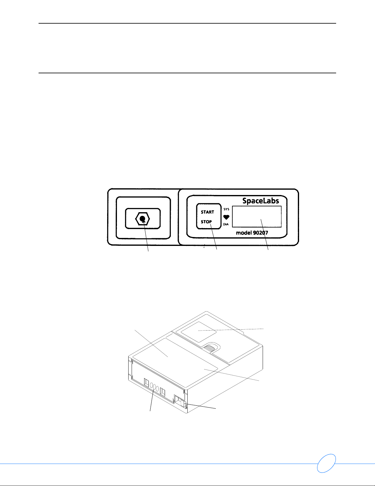
Front Panel
The front panel of the monitor includes the LCD display, the cuff hose connector, and the
START/STOP button. The figure below illustrates the ABP front panel.
90207 Ambulatory Blood Pressure Monitor Service Manual
cuff hose connector START/STOP button 4-digit LCD
Figure 1-2: Front panel
Rear and Top View
The rear panel of the monitor contains the communications port and the power ON/OFF switch.
operating instructions
communications port
unit ON/OFF switch
Figure 1-3: Rear panel and top panel
identification label
(serial number)
battery compartment
The top panel provides the unit’s model number, serial numbers, and abbreviated operation
instructions.
1-2
Page 7

90207 Ambulatory Blood Pressure Monitor Service Manual
ABP System Options
ABP analysis systems are used to program the ABP monitor, retrieve collected patient data, and
generate blood pressure reports from the acquired data. Current analysis systems available are:
• Model 90121 Ambulatory Blood Pressure Report Management System
• Model 90219-02 Personal Computer Direct Interface software for IBM PC XT or AT
compatible (5.25-inch diskettes)
• Model 90219-03 Base Station Interface software for connection by modem
• Model 90219-05 PC Direct Interface software for FT Holter Analysis Workstations
• Model 90229 Local Report Generator
• Model 90239A Report Generator with thermal printer
• Model 92506 Ambulatory Blood Pressure Management System
Spacelabs Medical software is available for both direct and remote ABP monitoring and reporting.
Refer to Spacelabs Medical Model 90219 ABP PC Interface/Base Station Interface Operations
Manual (P/N 070-0238-xx) for descriptions of the available options and operation configurations.
Introduction
1-3
Page 8

Page 9

Contents
Caution
Note:
Installation
Hardware Requirements . . . . . . . . . . . . . . . . . . . . . . . . . . . . . . . . . . . . . . . . . . . . . . . 1
Setup Instructions for the 90121 . . . . . . . . . . . . . . . . . . . . . . . . . . . . . . . . . . . . . . . . . 1
Setup Instructions for the 90219 and 92506 . . . . . . . . . . . . . . . . . . . . . . . . . . . . . . . . 2
Installation . . . . . . . . . . . . . . . . . . . . . . . . . . . . . . . . . . . . . . . . . . . . . . . . . . . . . . . . . .2
Observe precautions for handling electrostatic-sensitive devices!
• Never touch electrostatic-sensitive electronic components without following proper anti-
static procedures, including the use of an ESD wrist band and mat. An electrostatic
discharge from your fingers can permanently damage electronic components.
• All static-sensitive electronic components are packaged in static-shielding bags. Retain the
bag for repackaging the component should you need to store it or return it to Spacelabs
Medical for any reason.
Hardware Requirements
For analysis systems using an IBM PC XT or AT compatible computer, the following hardware is
required to run the ABP analysis systems (except for the 90229 and 90239A).
An IBM PC XT or AT compatible computer with the following features:
One floppy disk and one hard disk drive with a minimum of 512 KB available random access
memory (RAM).
IBM color graphics card with a color monitor, or a composite (black and white) monitor, or a
Hercules monochrome graphics card with a monochrome monitor.
At least one available serial port for the Model 90219-02, 03.
Setup Instructions for the 90121
1 Start Microsoft Windows.
2 Insert the ABP Report Management System Setup disk in drive A.
3 From the File menu, choose Run.
4 Type A:SETUP and press Enter.
5 When prompted, choose the desired operating language.
6 When prompted, enter the desired directory location of the ABP Report Management System.
7 When prompted, remove the Setup disk and insert Program Disk #1 into drive A.
8 When prompted, remove the Program Disk #1 and insert Program Disk #2 into drive A.
9 When prompted, restart the Windows operating system and remove the Program Disk #2.
2-1
Page 10

90207 Ambulatory Blood Pressure Monitor Service Manual
Setup Instructions for the 90219 and 92506
Note:
Refer to the 90219 Ambulatory Blood Pressure PC Base Station Interface (P/N 070-0238-xx)
or the 92506 Ambulatory Blood Pressure Report Management System Client Application (P/N
070-0932-00) for setup and operating instructions.
Installation
Data collected by the Model 90207 ABP monitor may either be transferred to a standalone report
generator or to an ABP analysis system running on an IBM PC XT/AT/PS2 or equivalent computer
for data analysis, report printing, and archiving.
Five modes of data interface operation are possible:
• Standalone Report Generator (a 90229 or 90239A Report Generator)
• PC Interface (direct connect using a 90219-02 or 90219-05 PCI for FT1000/FT2000/FT3000)
• ABP Base Station (modem connection using a 90219-03).
• ABP Report Management System 92506
• ABP Report Management System 90121
Caution
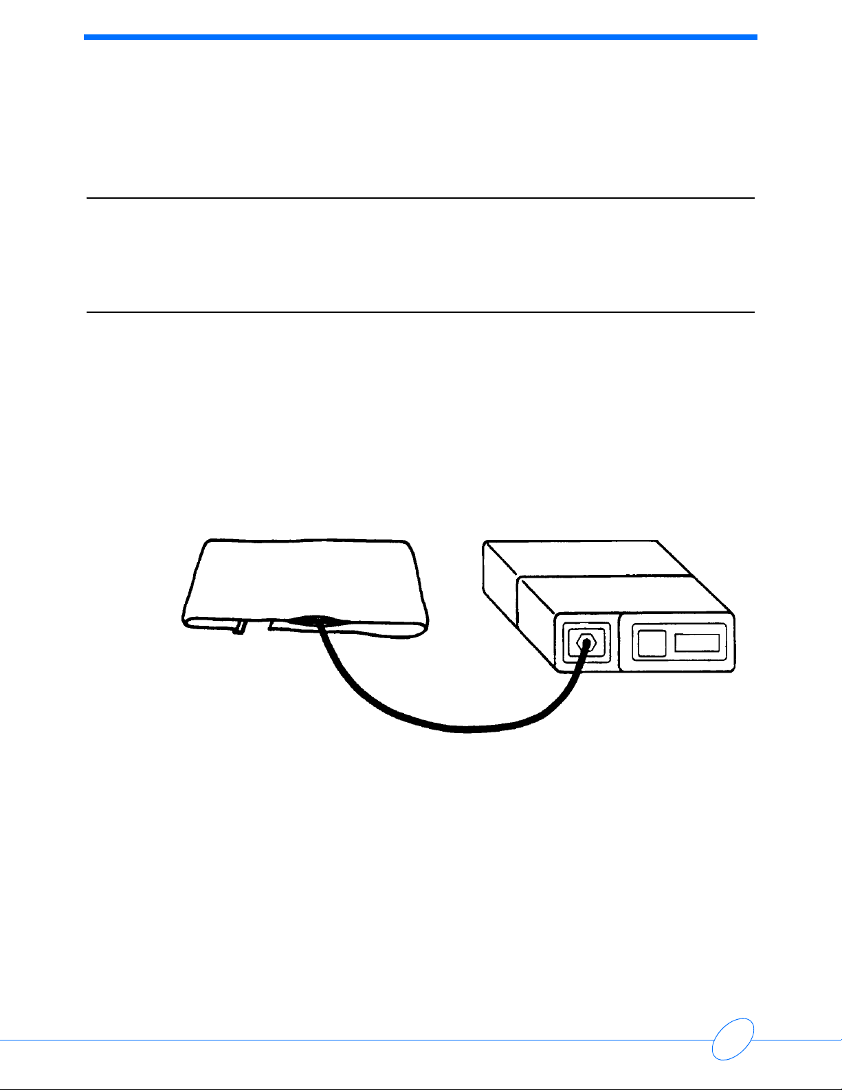
Refer to the appropriate operations manuals for setup configurations and initialization instructions.
Prior to patient monitoring, the ABP analysis system must initialize the ABP monitor.
The monitor should be disconnected from the patient during initialization. Be sure that
power to all hardware is OFF when connecting the ABP monitor for initialization. If
power switches are left ON during the connections, improper operation can result.
2-2
Page 11

Contents
Power Supplies . . . . . . . . . . . . . . . . . . . . . . . . . . . . . . . . . . . . . . . . . . . . . . . . . . . . . . 1
90207 Block Diagram . . . . . . . . . . . . . . . . . . . . . . . . . . . . . . . . . . . . . . . . . . . . . . . . . 4
Wake Up and Power Up Logic . . . . . . . . . . . . . . . . . . . . . . . . . . . . . . . . . . . . . . . . . . 5
Pressure Amplifier . . . . . . . . . . . . . . . . . . . . . . . . . . . . . . . . . . . . . . . . . . . . . . . . . . . . 7
Oscillometric Amplifier . . . . . . . . . . . . . . . . . . . . . . . . . . . . . . . . . . . . . . . . . . . . . . . . . 8
Digital Circuitry Display Board . . . . . . . . . . . . . . . . . . . . . . . . . . . . . . . . . . . . . . . . . . . 8
Real-Time Clock . . . . . . . . . . . . . . . . . . . . . . . . . . . . . . . . . . . . . . . . . . . . . . . . . . . . . 8
RAM. . . . . . . . . . . . . . . . . . . . . . . . . . . . . . . . . . . . . . . . . . . . . . . . . . . . . . . . . . . . . . . 8
Addressing and Control Lines . . . . . . . . . . . . . . . . . . . . . . . . . . . . . . . . . . . . . . . . . . . 9
Communications RS-232 Connector . . . . . . . . . . . . . . . . . . . . . . . . . . . . . . . . . . . . . . 9
Microprocessor . . . . . . . . . . . . . . . . . . . . . . . . . . . . . . . . . . . . . . . . . . . . . . . . . . . . . . 9
Power Supplies
Theory
All power required for operation of the Model 90207 ABP Monitor is derived from the four userinstalled AA cells. A 3-volt lithium battery provides memory (CMOS) backup.
Power Converter
A MAXIM “MAX631” step-up converter develops a +5 unregulated voltage whenever battery
potential drops below approximately +5.7 volts. This converter also provides an additional 45 kHz
square wave output to develop the +10 and -5.0 volt unregulated supplies.
+5 Unregulated Supply
The +5 volt unregulated supply is powered directly from +VPS (main battery voltage) through a
diode when the voltage is above +5.7 volts, and is powered by the step-up convertor when the
voltage drops below approximately +5.7 volts. The step-up convertor prevents the +5 unregulated
supply from dropping below +5.0 volts.
If the +5 unregulated power supply drops below 5.0 volts, the RAM protect circuit asserts a reset
signal to the processor that protects unit memory from a data loss during a power collapse. A startup processor reset signal with a 40 msec time constant is provided when power is initially applied.
The +5 unregulated supply needs approximately 30 msec to reach its full potential. This requires
that the processor be held in a reset condition for approximately 70 msec after unit power is first
applied.
Battery OK Status
The 90207 main battery voltage is monitored by reading the BAT VOLTS with an A/D convertor. A
low lithium battery is detected by reading a sample of the lithium battery BB VOLTS with an A/D
convertor.
3-1
Page 12

90207 Ambulatory Blood Pressure Monitor Service Manual
Power Enable
The power converter is activated when main battery voltage (+VPS) is first applied to the
converter’s step-up inductor. Three control lines determine if the +VPS supply is turned ON:
•PWR_ENABLE
•C_CON
• SHUTDOWN
PWR_ENABLE activates the various power supplies during a measurement or clock update.
The C_CON line (cable connected) keeps the power supplies active whenever the
communications cable is connected to the unit.
SHUTDOWN overrides both the PWR_ENABLE and C_CON lines to cause a power shutdown in
the event of a detected fault condition.
A/D Voltage References
The A/D converter uses two voltage references:
+ADR (+3.672 volts adjustable)
+ADR LOW (+1.022 volts)
Both are developed from a precision source (an LM358-1.2) that establishes a voltage reference
(+ADR), which is adjusted to +3.672 volts.
+4.7 Volts
The +4.7 volt regulator circuit compares a divided-down sample of the +4.7 volt supply output
against the +ADR reference and adjusts the drive for the two pass transistors (FETs) to
compensate for differences between the reference and the output voltages.
Two FETs are used as pass transistors to reduce the voltage drop across them. The +4.7 volt
supply provides most of the secondary power and sources approximately 25 mA.
+8.6 VREF Volts
The +8.6 VREF is developed from the +10 volt unregulated supply. The +8.6 VREF regulator is
similar to the +4.7 regulator, except that only one FET is needed, and there are two resistors in the
output drive of the circuit’s operational amplifier. These resistors ensure that the FET can be
turned ON or OFF at the minimum specified output voltage extremes of the OP Amp.
The +8.6 VREF sources approximately 1.6 mA to the pressure transducer and smaller amounts of
current to other circuits to produce a total current drain of about 2 mA.
3-2
Page 13

90207 Ambulatory Blood Pressure Monitor Service Manual
Other Power Sources
In addition to the regulated power supplies, there are five other power sources in the 90207:
+VSW, +VPS, +VSB, +VAA, and +VBB
+VSW is the voltage coming directly from the unit’s main batteries through the power ON/OFF
switch. This supply becomes active as soon as the power switch is ON.
+VPS is the power converter supply. When enabled, it is at about the same potential as +VSW,
and it is enabled to awaken the microprocessor.
+VSB is activated when +VSW is up and is a diode drop less than +VSW or +4.7 volts, depending
on which supply happens to be at the higher voltage.
+VAA supplies the main battery voltage to the 90207 clock and RAM chips when the power switch
is OFF and main batteries are present. This design prevents any unnecessary power drain from
the unit’s lithium battery.
+VBB is the backup battery supply. Its potential is always a diode drop down from the voltage at
+VSB or the backup battery potential, whichever happens to be at the higher voltage.
There are two conditions when the +VBB supply will operate from the backup battery:
• the main batteries have been removed
• the main batteries are discharged below 3.0 volts
Theory
3-3
Page 14
90207 Ambulatory Blood Pressure Monitor Service Manual
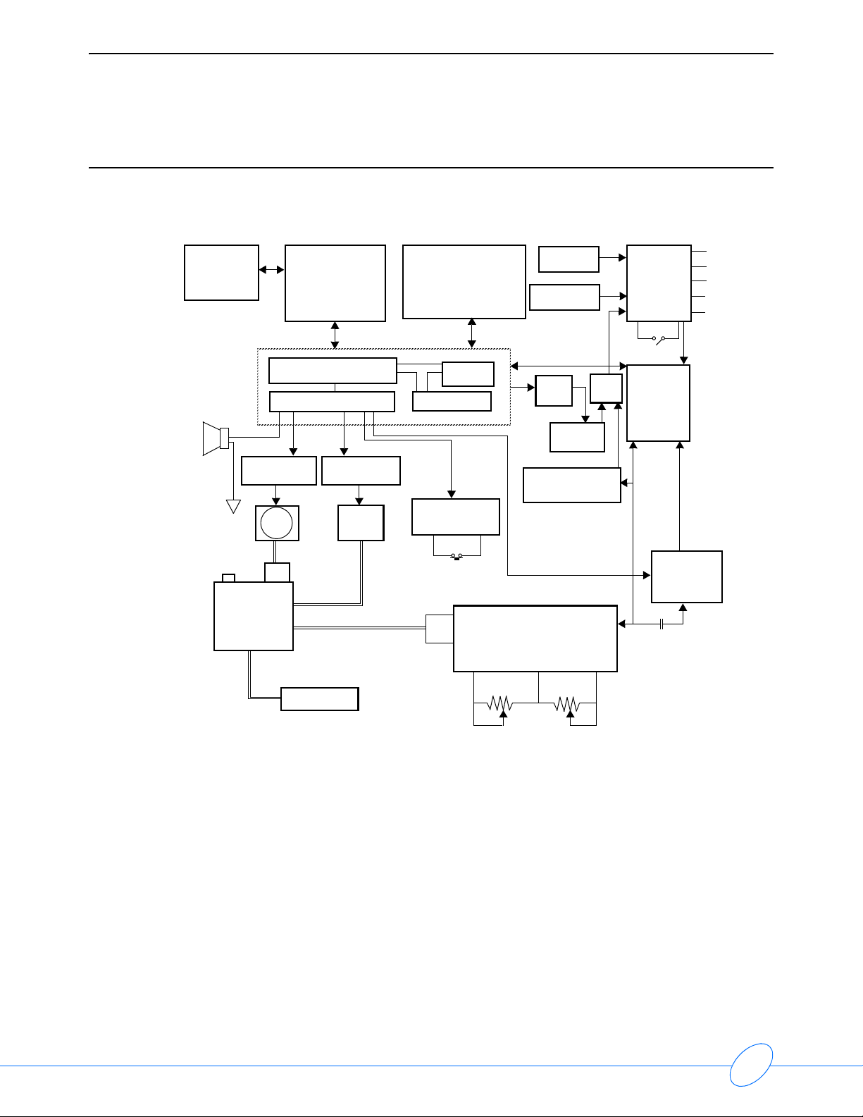
90207 Block Diagram
IR
serial
I/O
comm. port
speaker
internal
overpressure
relief valve
assembly
motor speed
control circuit
pump
manifold
IR
transmitter/
receiver
CPU / internal ROM
device latch
air
internal
check
valve
central processing
valve ON
control circuit
air
valve
LCD screen
address logic
hold
start up logic
Star t/ Stop
button
pressure
transducer
RAM
4 AA cells
3 volt lithium
backup battery
data/control
real
time
clock
watch dog
timer
over pressure
detector
gain and DC restore
pressure amplifier
fault
detect
power
supply
ON/OFF
switch
oscillometric
amplifier
oscillometric
amplifier
AC coupling
+8.6 Ref
+4.7 V
+5 UR
+10 UR
-5 UR
low
batteries
pressure cuff
gain adjust offset adjust
Figure 3-1: 90207 block diagram
3-4
Page 15

90207 Ambulatory Blood Pressure Monitor Service Manual
Wake Up and Power Up Logic
The 90207 power up sequence can be initiated by any of the following actions:
• Power START/STOP switch turned ON
• START/STOP switch depressed
• REAL TIME CLOCK generates minute change pulse
• IR serial RS-232 cable connected to communications port
The first three of the above actions trigger a wake-up pulse from a one-shot generator to assert the
PWR_ENABLE line and to enable the converter supply. When asserted, the PWR_ENABLE line
applies power to the microprocessor and generates a restart condition, causing the 90207 circuits
to awaken. The microprocessor then sets the HOLD line high to keep the converter supply up,
even after the wake-up one-shot pulse has timed out (the wake-up one-shot pulse has a duration
of approximately 120 msec).
After a wake-up, the microprocessor determines which event initiated the wake-up:
• It checks the C_CON (cable connected) line to determine if the IR RS-232 serial cable
activated the supplies.
• It checks the START/STOP line to see if this button is being pressed.
• It checks the PWR_SW line to see if the unit was just powered ON.
Theory
If none of these three conditions was responsible for waking up the unit, the minute timer is
assumed to have generated the wake-up pulse.
START/STOP Button
Pressing the START/STOP button triggers the wake-up one-shot generator and also generates an
interrupt to the microprocessor that is processed after the converter supplies are activated. The
microprocessor has a restart time of about 70 msec. After the restart time, the microprocessor
asserts the HOLD line and processes the interrupt (if the IR RS-232 cable is not connected), which
initiates the restart.
Power Switch
When the main power switch contacts are closed, power (+VSB) is applied to a power switch flipflop circuit. This flip-flop is then cleared and the PWR_SW line to the processor goes high (since
the processor is not yet powered ON, a resistor is used to protect the microprocessor input).
At the same time, the wake-up one-shot generator is triggered. This in turn activates the converter
supplies and awakens the microprocessor. The microprocessor now checks for conditions
START/STOP and C_CON. The PWR_SW line is read to determine if the power-up condition was
initiated by the power switch being ON. If ON, the HOLD line is asserted to clear the PWR_SW
line.
3-5
Page 16

90207 Ambulatory Blood Pressure Monitor Service Manual
Minute Pulse
The clock produces a pulse with a duration of 30 seconds every minute. The leading edge of this
pulse causes the minute timer flip-flop to change states. A narrow pulse (about 500 nsec) is
generated that also resets the flip-flop. This pulse triggers the wake-up one-shot, which in turn
powers up the converter and activates the microprocessor.
After waking up, the microprocessor first checks to see if any of the three possible wake-up
conditions has awakened it (C_CON, START/STOP LINE, or PWR_SW). If none of these three
have awakened the microprocessor, the microprocessor then asserts the HOLD line and
determines if it is time for a pressure reading. If it is time for pressure reading, the reading is
initiated; if it is not time for a pressure reading, the display time is updated, the HOLD line is
removed, and the microprocessor returns to its sleep state.
Cable Connection
If a cable is connected to the 90207 RS-232 communications connector and the power switch is in
the ON position, the power converter will be activated, bringing up the microprocessor. When
receiving a C_CON wake-up, the microprocessor gives it priority over the other three wake-up
conditions. A C_CON wake-up also prevents the power convertor from being deactivated as a
result of a shutdown fault, which might be generated by the watch dog timer or overpressure
detector.
After wake-up, the microprocessor goes into a listening mode and waits for instructions from the
attached computer. These instructions adhere to the ABP communications protocol.
Second Pulse
The SECONDS line from the unit’s real-time clock is monitored by the watch dog timer to
determine how long a pressure reading takes. When the unit wakes up, a reset signal is sent to the
watch dog timer, setting it to zero time. When the watch dog counts 256 second pulses, it
generates a pulse to activate the fault shutdown flip-flop circuit. The SECONDS line also goes to
the display circuit where it is used to blink the display colon and change polarity to the LCD
display.
Watch Dog Timer
The watch dog timer ensures that the cuff cannot remain inflated if the 90207 software crashes.
This timer begins counting second pulses from the real-time clock at converter power up. When it
counts up to 256-second pulses, the diode-connected outputs of the counter go high, causing a
transistor to pull low on the trigger input of the fault shutdown one-shot generator. This triggers a
25-second pulse, which asserts the shutdown line.
3-6
Page 17

90207 Ambulatory Blood Pressure Monitor Service Manual
Fault Shutdown
The fault shutdown circuitry causes the power converter to shut down. It also disables the
pressure pump and opens the pressure release valve until the shutdown circuit times out in
approximately 25 seconds. Shutdown can be caused by two conditions:
• There is an overpressure situation that is not detected by software.
• The pressure reading takes longer than 256 seconds. This duration indicates a software
crash, because there is also a 180-second software time-out that should have already stopped
the reading.
Overpressure Detector
In addition to software overpressure detecting, there is also a hardware overpressure detector
(at approximately 310 mmHg) that detects an overpressure situation that lasts longer than one-half
of a second. This small delay prevents motion artifacts from causing false overpressure detection.
Pressure Amplifier
The pressure amplifier circuitry amplifies voltage produced across the pressure transducer. This
voltage is proportional to the pressure in the arm cuff. The pressure transducer requires
compensation to make the voltage output linear with pressure. This compensation is
accomplished with a reference voltage and a current source. The current source provides an
output that increases as the voltage across the bridge decreases. This linearizes the transducer’s
output voltage.
Theory
Voltage across the transducer is amplified differentially and converted into single-ended voltage.
This voltage is amplified and sent to the A/D converter (ADC0848), the oscillometric amplifier, and
the overpressure detector.
Offset Adjust
Transducer offset is nulled out using a pressure offset adjustment. Minor variations in the offset
are tracked and compensated for through software.
Gain Adjust
Variations in gain can be compensated for with gain adjustment. The voltage gain to the A/D
converter is +14.4 mv/mmHg. This voltage is offset by about 0.2 volts. The 0.2 volts is inserted into
the last stage to prevent the signal to the A/D converter from going negative. The 0.2-volt offset is
subtracted with software.
Pressure Amplifier Filters
Some filtering is done in the pressure channel to reduce the effect of the pumping action, which
adds pulses to the pressure in the cuff. A 23-Hz low pass filter serves this purpose. The R-C
combination at the pressure output prevents the A/D converter loading from affecting the
oscillometric waveform.
3-7
Page 18

90207 Ambulatory Blood Pressure Monitor Service Manual
Oscillometric Amplifier
The first two stages of the oscillometric amplifier are a 2-pole low-pass filter and a 2-pole highpass filter. Together, these filters produce an insertion loss of 30%. The center frequency of the
pass band is 2 Hz; the 3-db points are at about 0.9 Hz and 5.5 Hz. During cuff bleeds and cuff
inflation, the high-pass filter is restored to charge the coupling capacitor up to the new pressure
level voltage. This helps reduce filter settling time.
Filtering has the effect of narrowing the oscillometric pulse width and generating a pulse with an
amplitude that is proportional to the rising edge of the oscillometric input waveform and its original
amplitude. The oscillometric pulse is similar to a half-sine wave with an extended trailing edge.
Gain Switching
Gain switching is provided by the oscillometric amplifier to account for varying amplitudes of the
oscillometric pulse. Switching is done by using switching gain resistors with analog switches
(DG211) selected by the GAIN_0 and GAIN_1 lines. Gain can be selected at 2, 4, 8, or 16.
Offset and Limiting
The offset stage offsets the voltage to the A/D converter to prevent negative voltages from going to
the converter. The input offset of the amplifiers can cause as much as 0.6 volts of unwanted offset
at the oscillometric output. Offset is subtracted out with software.
The last stage in the oscillometric amplifier limits the output swing from 0 to +4.7 volts to prevent
over-driving the A/D converter input.
Digital Circuitry Display Board
Information is sent from the microprocessor to the LCD controller by a serial bus (CBUS). The
LCD controller activates the necessary segments separately to display information on the 4segment LCD. The microprocessor determines what segments are to be turned on, sending this
information to the controller.
An exclusive OR gate blinks the colons once each second when in the clock mode, and it also
changes polarity of the drive.
Real-Time Clock
The real-time clock uses a serial data bus to send and receive information. This bidirectional bus is
divided into two lines (transmit and receive) that go to the microprocessor. If the main batteries are
removed, the clock will be backed up for approximately 2 minutes by the 3-volt lithium cell.
RAM
RAM is a 32 KB x 8 bit device for storing both patient collected information and programmed
information. RAM data is backed up during main battery removal by the 3-volt lithium cell.
3-8
Page 19

90207 Ambulatory Blood Pressure Monitor Service Manual
Addressing and Control Lines
Unit addressing and control is accomplished with a combination of microprocessor ports, two
latches, and one-half of a multiplexer circuit. The 74HC174 latch controls the motor, valve, alert,
gain switching, and hold line. A 74HC373 provides address latching for the RAM.
Communications RS-232 Connector
The 90207 communications connector is a modified RS-232 interface. When the communications
cable (IR cable) is connected to the back of the 90207, a reed relay is activated, causing power to
be applied to the ABP unit.
The microprocessor checks and determines that the C_CON line is asserted. It then goes into
communication mode. The microprocessor must then determine whether the cable is
communicating with a modem, a PC direct interface, or a local report generator. It then responds
accordingly.
Communications are accomplished by means of a transmit and a receive line. The data is
converted into IR signals.
Theory
Microprocessor
The 90207 uses a 80C51 microprocessor with a 7.272-MHz crystal. This chip contains on board
RAM and ROM. Four 8-bit ports provide the data lines, the addressing, and the control and serial
bus lines.
The on-board ROM provides routines for communications and start up. The majority of the
program is loaded into RAM using the IR RS-232 port.
One interrupt is used, and it is initiated by these following conditions:
• The START/STOP line goes low
• The PWR_SW line and the ADC INT lines go low (lowest-priority interrupt)
3-9
Page 20

Page 21

Contents
Caution
Note:
Maintenance
Cleaning . . . . . . . . . . . . . . . . . . . . . . . . . . . . . . . . . . . . . . . . . . . . . . . . . . . . . . . . . . . 1
Battery Replacement . . . . . . . . . . . . . . . . . . . . . . . . . . . . . . . . . . . . . . . . . . . . . . . . . . 2
Battery Clip Upgrade . . . . . . . . . . . . . . . . . . . . . . . . . . . . . . . . . . . . . . . . . . . . . . . . . . 3
90207 Disassembly Procedure . . . . . . . . . . . . . . . . . . . . . . . . . . . . . . . . . . . . . . . . . . 5
Calibration Procedures . . . . . . . . . . . . . . . . . . . . . . . . . . . . . . . . . . . . . . . . . . . . . . . . 8
Observe precautions for handling electrostatic-sensitive devices!
• Never touch electrostatic-sensitive electronic components without following proper anti-
static procedures, including the use of an ESD wrist band and mat. An electrostatic
discharge from your fingers can permanently damage electronic components.
• All static-sensitive electronic components are packaged in static-shielding bags. Retain the
bag for repackaging the component should you need to store it or return it to Spacelabs
Medical for any reason.
Periodic maintenance consists of cleaning the exterior of the unit, replacing or recharging the
monitor batteries, and calibrating the unit for accurate operation.
Cleaning
Use a soft, damp cloth and mild detergent mixed with water to wipe the exterior of the monitor.
Clean the carrying pouch and air hose with isopropyl alcohol.
The cuff wrap may be sterilized only by ethylene oxide (ETO) sterilization methods, using standard
hospital procedures. Use standard aeration techniques after sterilization. Small soiled or stained
areas may be cleaned by gentle scrubbing with a sponge or cloth soaked in a mild soap and water
solution.
The cuff wrap (with the air bladder removed) is machine washable on “delicate” cycle only. Do not
wash with bed linens and gowns or in large commercial-type washers.
To remove the bladder for cleaning, refer to the figures on the next page and follow these
steps:
1 Using your fingers only, fold or roll up the bladder inside the cuff. Do not use pencils, pens, or
2 Remove the bladder through the hose exit opening. After the bladder has been removed, be
3 After washing and drying the cuff, reinstall the bladder in the reverse order, as previously
other hard objects, because damage to the bladder could easily occur.
sure to again mate the hook-and-loop surfaces on the cuff before washing.
described. Make certain that any folds in the bladder are removed before inserting it back inside
the cuff.
Note:
The bladder may be installed with the hose exiting the second cuff opening. However, the
bladder must be positioned with its long side toward the center of the cuff.
4-1
Page 22
90207 Ambulatory Blood Pressure Monitor Service Manual
Battery Replacement
Two types of replaceable batteries are used in the 90207 ABP Monitor: four AA batteries
(Spacelabs Medical part number 146-5011-00) that power the cuff air pump, and one lithium
battery (3 volts, Spacelabs Medical P/N 146-0008-00) that preserves the information held in the
monitor’s memory circuits.
If alkaline batteries are used for the AA batteries, they must be replaced after each patient use.
Nickel cadmium batteries require a full recharge after each use. The lithium battery should be
replaced with a fresh battery every three years.
AA Batteries
Note:
If batteries are being replaced during patient testing, their replacement must be completed
within 1 minute to guarantee successful resumption of the test.
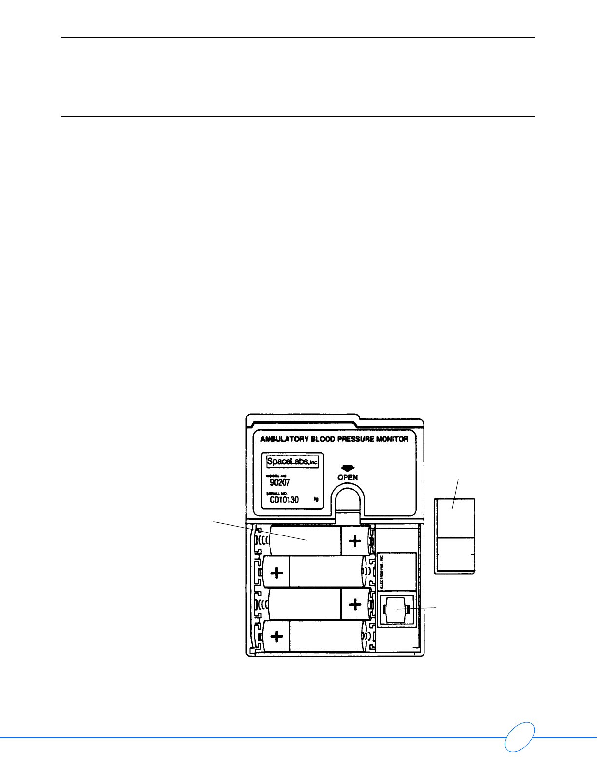
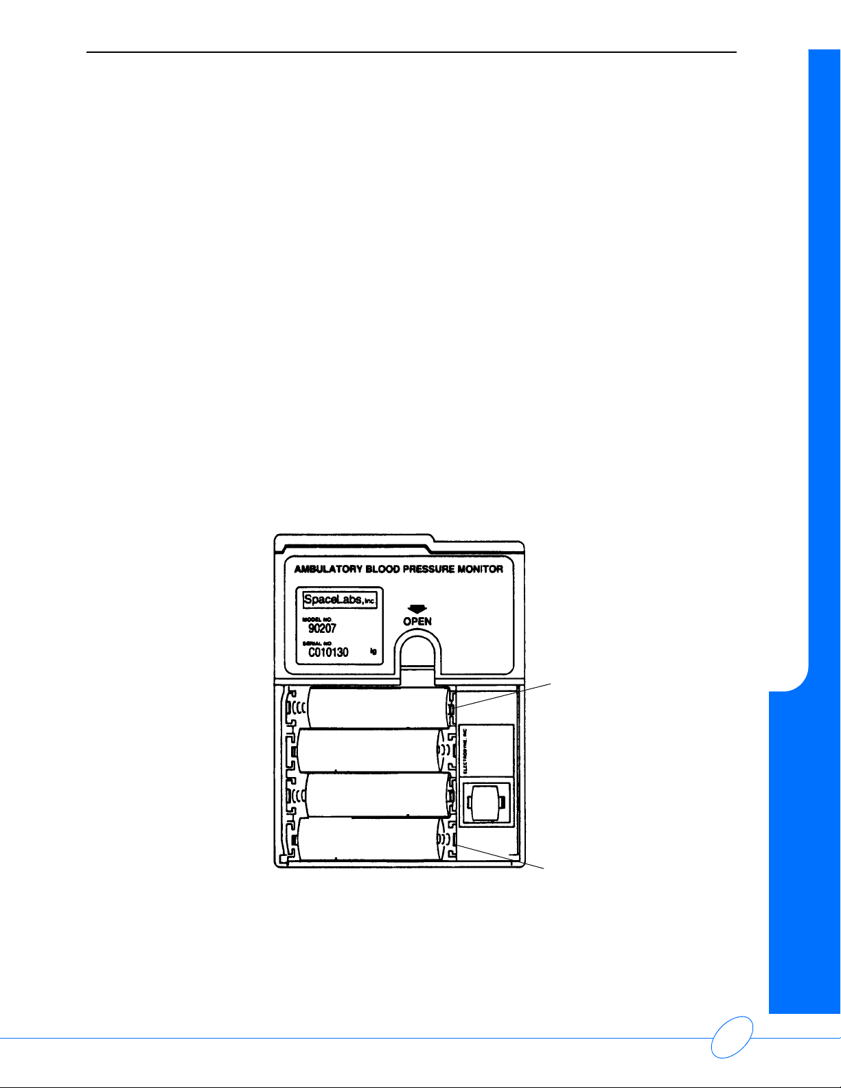
To replace the four monitor AA batteries:
1 Power the monitor OFF using its rear panel ON/OFF switch.
2 Remove the battery compartment cover plate by pulling back and up on the provided latch.
3 If present, remove the old AA batteries from the monitor and replace each with a fresh alkaline
(or fully charged nickel cadmium) battery, being careful to observe the voltage polarity (+ or -)
as identified in
4 AA batteries
Figure 4-1.
Lithium
battery cover.
Note shape of
cover. It will
insert in one
position only.
lithium battery
Figure 4-1: Battery compartment
4-2
Page 23

90207 Ambulatory Blood Pressure Monitor Service Manual
Note:
• The monitor will not operate if either the alkaline or the lithium batteries are incorrectly
installed.
• If the monitor is going to be stored for over two weeks, remove the batteries to prevent the
possibility of leakage or discharge. Spacelabs Medical is not responsible for product
damage incurred as a result of battery leakage. In the event that your unit has been
damaged from a leaky battery, contact the battery manufacturer for any recoverable repair
or replacement costs.
4 After replacing the batteries, gently replace the battery cover and secure the latch.
5 Turn ON the monitor. Check that the display is ON. If there is no display, power the monitor
OFF and refer to
Maintenance on page 4-1.
Lithium Battery
The expected life for the 3V lithium battery is 10 years; however, Spacelabs Medical recommends
that it be replaced before three years of use.
To replace the lithium battery:
1 Power OFF the monitor using the rear panel ON/OFF switch.
2 Remove the battery compartment cover plate by pulling back and up on the provided latch.
3 Remove the protective cover from the lithium battery, taking note of the battery position (polarity
of cell and socket indicators).
Maintenance
4 Remove the old lithium battery by carefully prying it out (curved forceps are recommended).
5 Install the new lithium battery, observing the correct polarity.
6 Replace the battery’s protective cover (step #3).
7 Replace the battery compartment cover plate (step #2).
Battery Clip Upgrade
Please verify that you have the part before beginning:
Quantity Part Number Description
3 131-1218-01 Battery clip, 90207
Tools Required
• Needle-nose pliers
• Fine-tipped flat screwdriver
4-3
Page 24
90207 Ambulatory Blood Pressure Monitor Service Manual
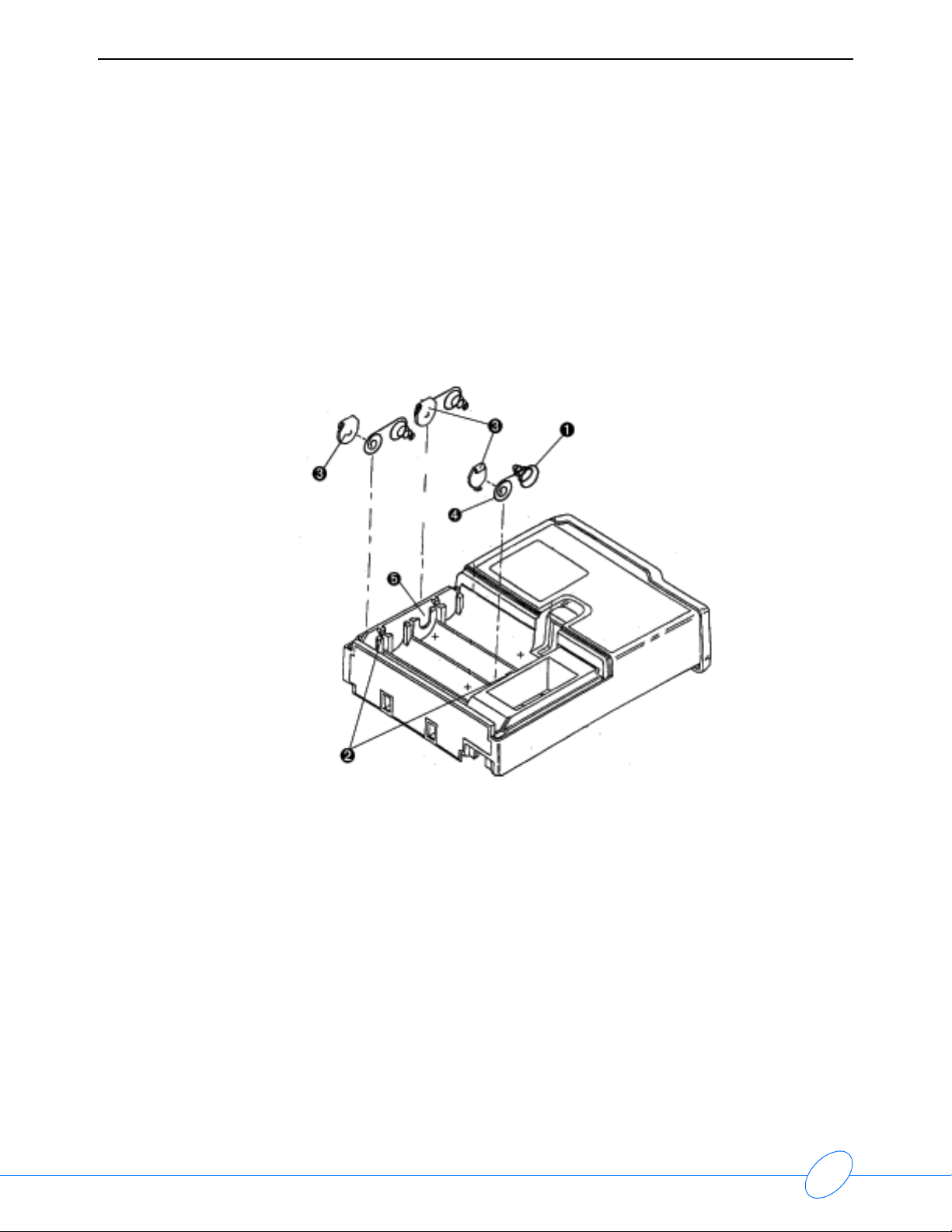
Installation Instructions
1 Remove the battery cover from the 90207. Refer to Figure 4-2: Battery contact clip installation.
2 Using a fine-tipped flat screwdriver, remove the three twin-spring contacts () by gently prying
the contacts out from under the molded retaining hooks (
Note:
Use extreme care not to break the retaining hooks.
3 Insert each new battery contact clip () over the short spring () (+ terminals) (refer to Battery
contact clip installation on page 4-4).
).
Figure 4-2: Battery contact clip installation
4 Orienting the metal bump on the contact toward the battery with all coils under the contact tab,
slide the contact and spring assembly back down into the case slots. Ensure that the contact is
inserted into the case slot (
5 Carefully press down and position the center part of the spring assembly under the plastic
retaining hook.
6 Ensure that each battery clip is securely in place and makes good contact with an installed
battery.
Note:
The last battery in the center of the unit does not require the installation of a battery clip.
) facing the battery slot.
4-4
Page 25
90207 Ambulatory Blood Pressure Monitor Service Manual
90207 Disassembly Procedure
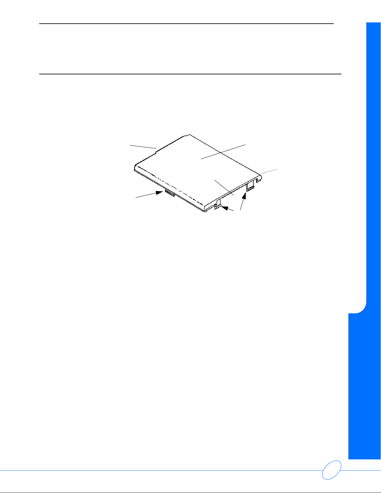
To remove the top case cover and gain access to the internal components:
1 At the rear of unit, use two small screwdrivers (or similar tools) to press in on the cover’s two
locking tabs until the tabs both clear contact with the rear panel (the tabs are located on each
side of the infrared connector, refer to
Maintenance
Figure 4-3: Top cover removal).
front
infrared connector
location
side tabs
Figure 4-3: Top cover removal
Aplly sufficient pressure to lift the cover and pull the two side tabs free. Be sure to pull from the
rear of the cover. The front of the cover is tucked under the front panel and it cannot be pulled
out until the locking tabs are free from the case.
2 When the locking tabs are pulled out of the case, pull the cover away from the front panel to
free it from the unit.
top case cover
rear
push in these two tabs
and pull cover up when
tabs clear rear panel
4-5
Page 26

90207 Ambulatory Blood Pressure Monitor Service Manual
Accuracy Procedure
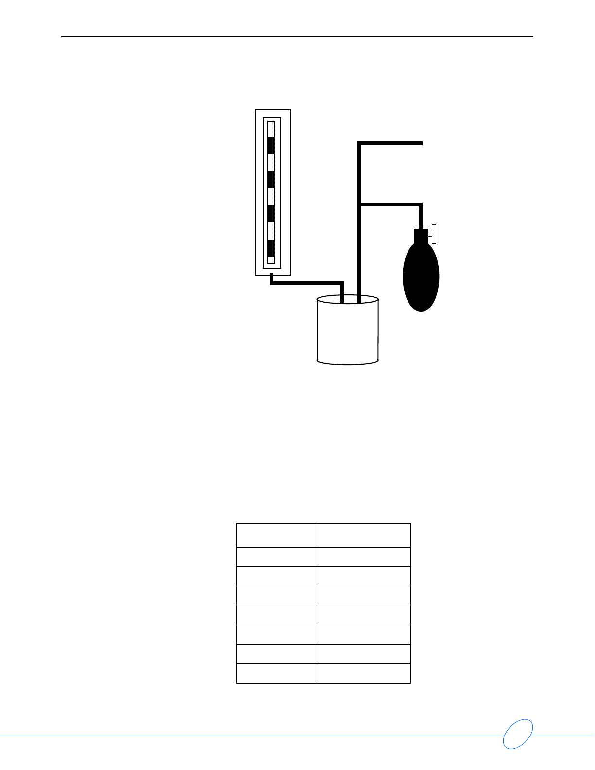
To check the accuracy of the monitor:
1 Disconnect the cuff hose from the monitor. Connect the T-tube splitter to the monitor pneumatic
connector and the sphygmomanometer.
2 Wrap the pressure cuff around the rigid cylinder, and then fasten the cuff. Connect the cuff hose
to the remaining connection on the T-tube splitter. The test setup should appear as shown
below.
016-0040-xx
712-0039-01 CALIBRATION KIT
TO SPHYGMOMONOMETER
TO CUFF/CYLINDER
Figure 4-4: T-Tube connection
TO MONITOR
4-6
Page 27

90207 Ambulatory Blood Pressure Monitor Service Manual
)RUXVHZLWK40RQLWRU4XLFN'LVFRQQHFW&XII&DQ
&RQQHFW
WR
6SK\JPRPRQRPHWHU
&RQQHFW
WR
4XLFN'LVFRQQHFW
)LWWLQJ&XII
&RQQHFW
WR
4
$%30RQLWRU
Maintenance
)RUXVHZLWK0RQLWRU/XHU)LWWLQJ&XII&DQ
&RQQHFW
WR
6SK\JPRPRQRPHWHU
5HPRYH/XHU%DUE7XELQJ
5HPRYH4XLFN
'LVFRQQHFW)LWWLQJ
3 Press START/STOP on the monitor; the monitor should read approximately 165. Compare the
readings on the monitor and the manometer as the pressure bleeds down. The monitor reading
should be within three millimeters or 2% of the manometer reading, whichever is greater
(± the accuracy of the manometer).
Note:
If the monitor pressure values fall outside the allowed tolerance, call your local Customer
Service Representative or Spacelabs Medical for servicing.
4 At the end of the procedure, the monitor displays an event code indicating that no dynamic
blood pressure measurements were obtained.
5 Disconnect the T-tube splitter from the monitor. Disconnect the air hose and
sphygmomanometer.
4-7
Page 28

90207 Ambulatory Blood Pressure Monitor Service Manual
Calibration Procedures
Complete the following procedures to calibrate the Model 90207 ABP Monitor.
Test Equipment Required
Note:
Any test equipment listed below can be replaced with equivalent models.
• 1 Tektronix 7603 or TDS420 oscilloscope
• 7A22 or AM502 Differential Amplifiers
• 7B53A Dual Time Base
• DM501A Digital Multimeter
• FG501A Function Generator
• PS503A Dual Power Supply
• BK 1630 DC Power Supply
• Fluke 8052A Digital Multimeter
• IBM PC-AT (or compatible) loaded with 90207 manometer mode software (P/N 063-0165-00)
and 90209 to PC cable assembly or 90219 software
• 90209 Data Interface Unit or 90219-02, -03
• IR Direct Connect Cable Assembly (P/N 012-0097-xx)
• Temperature-controlled soldering station
• Analog or digital sphygmomanometer
• Two-hole pressure can (made from empty pint paint can with lid and two 1/8-inch outer
diameter brass fittings soldered on)
• Squeeze bulb with tubing and T-fittings
• 1000 µF or greater capacitor
•1 µF capacitor
Tools Required
• Needle nose pliers
• Hemostats
• Diagonal cutters
• Small Phillips screwdriver
• Small flat-tip screwdriver
• Anti-static equipment
•Tweezers
• Small cleaning brush (acid brush)
• Small gauge wire strippers
• Utility knife
• Soldering iron with small tip
4-8
Page 29

90207 Ambulatory Blood Pressure Monitor Service Manual
Solvents/Compounds Required
• Isopropyl alcohol
• Rosin core solder
90207 Main Board Components
Refer to Figure 4-5 to identify test points and other components when conducting calibration and
verification procedures for PCBAs P/N 670-0303-10 (and earlier versions).
SW910 SW860
TP731
P710
Maintenance
TP730
TP631
TP630
L530
C533
U440
C432
C431
C330
R330
C250
R130
TP110
Figure 4-5: Main board components for P/N 670-0303-10 (and earlier versions)
4-9
Page 30

90207 Ambulatory Blood Pressure Monitor Service Manual
Figure 4-6: Main board components (front view) for P/N 670-0303-11 (and later versions)
4-10
Page 31

90207 Ambulatory Blood Pressure Monitor Service Manual
N1
Maintenance
N26
N10
N23
N18
N19
N9
N20
N17
N57
D534
N24
N11
N8
Figure 4-7: Main board components, back view, for P/N 670-0303-11 (and later versions)
Computer System Setup
The following equipment is required to set up the test computer required for 90207 calibration:
• IBM PC (or compatible) loaded with manometer mode software (P/N 063-0165-00)
• 90209 Data Interface Unit or 90219 PCDI software
• 90209 to PC Cable Assembly
• IR Direct Connect Cable Assembly
4-11
Page 32

90207 Ambulatory Blood Pressure Monitor Service Manual
To set up the computer system (refer to Figure 4-8):
computer system block diagram
90219
IBM PC
with 90219
software
IR cable
012-0097-xx
Figure 4-8: Computer system block diagram
1 Connect power to the 90209 Data Interface Unit.
2 Connect the 90209 to PC cable between the 90209 and the IBM PC. Use the proper cable for
either a PC AT or XT, depending on the computer being used.
90207
3 Connect the IR Direct Connect Cable Assembly to the 90209 at the 90207 connection.
Note:
• Refer to the 90219 operations manual if not using a 90209 for these procedures.
• The test equipment settings specified in these procedures are for reference only.
• The power supply must have a 1000 µf or greater capacitor connected between the plus
(+) and minus (-) terminals and must be
within three inches of where the power is applied
to the flex board.
• The calibration adjustment on the dual time base must remain in the CAL position (fully
clockwise) when making timing measurements. The SOURCE selection should remain in
the INT position.
• The ground wire of the test lead must be connected to the power ground of the circuit
board under test whenever measurements are made using the differential amplifier.
4-12
Page 33
90207 Ambulatory Blood Pressure Monitor Service Manual
Power Supply Check
To check the Model 90207 power supply:
1 Set your oscilloscope as shown below.
Time/Div 5 ms
Volts/Div 10 mV
Mode AUTO
+ Input AC
Coupling AC
HF -3 dB Point 10kHz
LF -3 dB point DC
2 Set the power supply output to 5.7 VDC ±0.1 VDC.
3 Connect the power supply to the 90207 monitor at the positive (+) and negative (-) AA battery
terminals:
Maintenance
+ lead of power supply
- lead of power supply
Figure 4-9: Power supply
4 Ensure that the ON/OFF switch (SW910) is in the OFF position. Verify a voltage reading of
0.0
V at +VSW (P710, pin 2). For P/N 670-0303-11 assemblies (and later versions), verify the
voltage at N9. Use N17 (AGND) as ground reference. Refer to
pad location.
Figure 4-7 on page 4-11 to verify
4-13
Page 34

90207 Ambulatory Blood Pressure Monitor Service Manual
5 Slide the ON/OFF switch to the ON position and verify the following:
a The LCD shows the current ROM version number followed by the time.
b A sleeping current draw of less than 300 µADC (monitor is in sleep state when LCD shows
time).
c A voltage reading of +5.7 VDC at +VSW.
6 Connect a jumper lead across the reed switch (SW860). The LCD will show “9999”.
7 Verify a current flow of less than 30 mA.
8 Verify a voltage reading of greater than +5.65 VDC at + VPS (L530) for P/N 670-0303-10 and
earlier versions. For P/N 670-0303-11 and later versions, verify the voltage reading at the
cathode side of D534. Refer to figure
9 For main board assemblies P/N 670-0303-10 (and earlier versions) set the ADR reference
voltage, measured at +C330, to 3.672
refer to
Main board assemblies of P/N 670-0303-11 (and later versions) require a board test fixture to
calibrate ADR. If ADR is out of specification, recalibrate on an ABP board test fixture. ADR can
be measured at N10. To locate this point, refer to
as ground reference.
Figure 4-5 on page 4-9.
Figure 4-7 on page 4-11.
V ± 0.001 V by adjusting point R330. To locate this point,
Figure 4-7 on page 4-11. Use N17 (AGND)
10 Refer to the table below and verify each voltage specification.
Note:
In the following checks and adjustments, TP730 must be used as a ground test point for board
assemblies P/N 670-0303-10 (and earlier versions). For board assemblies P/N 670-0303-11
(and later versions), use N17 (AGND) as ground reference. Refer to
to verify pin location.
Figure 4-7 on page 4-11
Power Supply Voltage Specifications
Table 1: Specifications for Board Assemblies 670-0303-10 and earlier versions
Supply Location
ADR Low TP731 1.022 1.009 to 1.035 <10
+4.7 V +C431 4.7 4.69 to 4.71 <50
+5 V UR +C432 5.45 5.1 to 5.65 <100
-5 V UR -C430 -4.45 -4.0 to -4.7 <50
+10 V UR +C533 9.75 9.0 to 10.5 <50
+8.6 V Ref +C250 8.6 8.575 to 8.625 <20
Voltage
(VDC)
Range (VDC)
Ripple
(mVPP)
4-14
Page 35

90207 Ambulatory Blood Pressure Monitor Service Manual
Table 2: Specifications for Board Assemblies P/N 670-0303-11 and later versions
Maintenance
Supply Location
ADR Low N8 1.022 1.009 to 1.035 <10
+4.7 V N11 4.7 4.69 to 4.71 <50
+5 V UR N18 5.45 5.1 to 5.65 <100
-5 V UR N23 -4.45 -4.0 to -4.7 <50
+10 V UR N19 9.75 9.0 to 10.5 <50
+8.6 V Ref N20 8.6 8.575 to 8.625 <20
Voltage
(VDC)
Range (VDC)
Ripple
(mVPP)
Amplifier Calibration
Pressure Amplifier
1 Monitor TP731, ADR_LOW, with a DVM. For P/N 670-0303-11 (and later versions), monitor N8.
Refer to
2 Check for 1.0224 V ±0.0144 V.
3 Monitor TP630, PRESS, with a DVM. Monitor N24, PRES_OUT, for P/N 670-0303-11
assemblies (and later versions). Refer to
Figure 4-7 on page 4-11.
Figure 4-7 on page 4-11.
4 For main board assemblies of P/N 670-0303-10 (and earlier versions), adjust R130 to
0.1872 V ± 0.005 V.
For main board assemblies of P/N 670-0303-11 (and later versions), the ABP system test
fixture is required to adjust pressure offset.
5 Connect the pressure bulb manometer and standard two-hole can to the input (refer to
Figure 4-10 on page 4-16). Clamp the hose to the bleed valve using the hemostats.
4-15
Page 36
90207 Ambulatory Blood Pressure Monitor Service Manual
to 90207
sphygmomanometer
two-hole can
squeeze bulb
Figure 4-10: Sphygmomanometer test configuration
6 Connect the 90207 monitor to the PC and run the manometer mode software.
7 Manually pump the bulb to apply 200 mmHg pressure to the system.
8 Verify a voltage reading of between 3.060 VDC and 3.070 VDC at TP630 (sphygmomanometer
and display must read 200
(and later versions). Refer to
mmHg). Monitor N24, PRES_OUT, for P/N 670-0303-11 assemblies
Figure 4-7 on page 4-11.
9 Check the following voltages for each given pressure reading (if any adjustment is made,
all pressure and voltages must be verified again).
Pressure Voltage
300 mmHg 4.507, ±0.02
250 mmHg 3.787, ±0.01
200 mmHg 3.067, ±0.01
150 mmHg 2.347, ±0.01
100 mmHg 1.627, ±0.02
50 mmHg 0.907, ±0.02
0 mmHg 0.187, ± 0.01
4-16
Page 37

90207 Ambulatory Blood Pressure Monitor Service Manual
Overpressure Detector
1 Monitor U440 pin 7 with an oscilloscope for main board assemblies P/N 670-0303-10 (and
earlier versions). Monitor N57 for main board assemblies P/N 670-0303-11 (and later versions).
Refer to Figure 4-7 on page 4-11.
2 Slowly increase the pressure while observing the manometer.
3 For P/N 670-0303-10 assemblies (and earlier versions), verify that U440 pin 7 goes low
between 305 mmHg and 320 mmHg. For P/N 670-0303-11 (and later versions), verify this
measurement at N57.
4 Relieve the pressure in the system.
Noise
1 Configure the oscilloscope as follows:
Model 7A22
Window: DC - 3 kHz
Volts/Div: 50 mV/Div
Input: AC +
Maintenance
2 Check TP630, PRESS, for <10 mV of noise. Monitor N24, PRES_OUT, for P/N 670-0303-11
assemblies (and later versions). Refer to
Figure 4-7 on page 4-11.
Oscillometric Bandpass
1 Connect a 1µF capacitor between the scope probe and TP631 (OSC_OUT) for P/N 670-0303-
10 assemblies (and earlier versions). For 670-0303-11 assemblies (and later versions),
connect the probe to N26 (OSC_OUT). Refer to
2 Set the oscilloscope (7A22) to AC, 20 mV/division.
3 For P/N 670-0303-10 assemblies (and earlier versions):
Set the function generator for sine wave, a frequency of 2.5 Hz, free run mode, -60 db (minimum
amplitude), and connect it to TP110.
For 670-0303-11 assemblies (and later versions):
Repeat the previous steps, but disregard the connection to TP110. Instead, connect to point
N1. Refer to
4 Adjust the amplitude of the function generator until the OSC_OUT pressure output signal is 100
millivolts, peak-to-peak.
Figure 4-7 on page 4-11 to verify the location of this point.
Figure 4-7 on page 4-11.
4-17
Page 38
90207 Ambulatory Blood Pressure Monitor Service Manual
2.5-Hz Signal on Percentage Scale
100%
0%
Figure 4-11: Signal on percentage scale
5 Decrease the frequency until the amplitude is 70%.
6 Verify that the frequency is 0.9 to 1.1 Hz.
7 Increase the frequency until the amplitude is at 70%.
8 Verify that the frequency is from 5 to 7 Hz.
9 Remove the capacitor and hemostats.
Backup Battery Check
To test the lithium battery current:
1 With a primary power supply connected across the main battery terminals, set a secondary
power supply for a 2.6 ±0.1 VDC output. Connect a current meter in series with the power
supply.
2 Remove the lithium battery from its holder.
3 With the 90207 power switched OFF, connect the power source to the 90207 at the lithium
battery holder terminals (pay attention to terminal polarity).
4 Turn the unit ON and start a reading by pressing the START/STOP button, and then verify that
an “Lbb” indication does not occur.
5 Decrease the lithium battery input voltage to 2.25 ±0.05 VDC.
6 Start a reading and verify that an “Lbb” indication does occur.
7 Reinstall the lithium battery removed in step 2 above.
8 Initialize the ABP monitor using one of the ABP systems. Set it to view pressure steps.
Functional Test
To test the operation of the Model 90207:
1 Set the primary power supply for a 5.7 VDC output.
2 Connect a current meter in series with the supply.
4-18
Page 39

90207 Ambulatory Blood Pressure Monitor Service Manual
3 Remove the four AA batteries from the main battery compartment of the 90207.
4 Connect the 5.7 VDC power source to the 90207 at the main battery terminals.
5 Turn ON the 90207. The display shows the current ROM version and then the current time; the
colon will be flashing.
6 Connect the sphygmomanometer test configuration (page 4-11) to the 90207.
7 Press the START/STOP button and verify the occurrence of two audible tones.
8 Verify that the display begins the countdown sequence; “5555”, “4444”, “3333”, “2222”, “1111”.
9 Verify that the pump starts, the current draw is less than 350 mA, and that the pump reaches
its target pressure of 175 mmHg, +/-8 mmHg.
10 Verify that the pressure bleeds down in increments of between 7 and 9 mmHg.
11 Verify a current drain of less than 55 mA during bleed down. Current spikes of approximately
70 mA are acceptable.
12 Verify a rapid succession of tones and a display reading of “EC 08”.
13 Verify that the display changes from showing the event code to showing the current time.
14 Verify that the monitor goes to a sleep mode with a current drain of less than 250 µA. Lower the
main battery input voltage to 4.8 ±0.03 VDC.
15 Attempt a reading by depressing the START/STOP button.
16 Verify that the display shows “LLL”, indicating a low main battery.
Maintenance
17 Increase the main battery input voltage to 5.0 ±0.03 VDC and attempt a reading.
18 Verify that the 90207 performs a normal reading.
19 Start another reading. Decrease the main battery input voltage to 4.1 VDC when the 90207
begins to pump.
20 Verify that an “LLL” indication does NOT occur.
21 Decrease the main battery input voltage to 3.9 VDC while the 90207 is still pumping.
22 Verify that an “LLL” indication occurs immediately.
23 Increase the main battery input voltage to 5.7 VDC.
24 Disconnect the primary power source and reinstall the four AA batteries (observe correct
polarity).
25 Assemble the 90207 module into the main body case. Make sure that the display board fits
completely into the window of the case.
26 Fit the case cover over the 90207 module and snap it into place.
27 Fit the tabs on the case battery cover into the hinges on the main body case; snap the cover in
place.
28 Reinitialize the 90207 monitor using the ABP program.
4-19
Page 40

90207 Ambulatory Blood Pressure Monitor Service Manual
Operation Verification
The following procedures verify that the 90207 ABP monitor’s blood pressure readings are
consistent with design standards.
Note:
These procedures refer to use of the DynaTech Nevada CuffLink Blood Pressure Simulator. If
you are using a different simulator, refer to its operator’s manual to determine equivalent tests.
Refer to the end of this Maintenance chapter for instructions on using the CuffLink simulator in
automatic or manual modes.
Equipment Required
• DynaTech Nevada CuffLink Noninvasive Blood Pressure Analyzer and associated tubing,
manuals, luer fittings (software version 2.0 or higher is required)
• 1/8 inch I. D. tubing (P/N 162-0019-00 or equivalent)
• Adult cuff
• Luer connector (P/N 103-0008-00)
Blood Pressure Simulator Preparation
1 Verify that the calibration sticker on the simulator is current. If it is not, the simulator will need
to be calibrated by the manufacturer or the authorized service facility.
2 Turn ON the CuffLink simulator and allow it to warm up for a minimum of 15 minutes.
3 Check the zero pressure by selecting ADAMS Adult from SelectBp in the Main menu.
4 Press ENT.
5 Press F5 to zero the pressure.
6 Press Esc to return to the Main menu.
7 Perform a leak rate check on the blood pressure simulator and associated tubing as follows:
a While in the Main menu, move the cursor to Press and select Leak Test by pressing ENT.
b Connect a squeeze bulb to the hose which will connect directly to the unit under test.
c Pump up the system pressure to approximately 170 mmHg.
d Wait 10 seconds for the pressure to stabilize.
e Press the START (F1) key on the CuffLink simulator and wait one minute while the leak
rate is measured.
f At the end of the minute, the leak rate will be displayed on the CuffLink display.
g If the leak rate is greater than 10 mmHg per minute, retighten all external hose connections
and repeat the test. If the system continues to fail, isolate each length of tubing to locate
the source of the leak. Repair the leak.
h Press the Esc key to return to the Main menu.
4-20
Page 41

90207 Ambulatory Blood Pressure Monitor Service Manual
90207 Preparation
1 Set up the ABP monitor by connecting it to the CuffLink.
2 Refer to the table below for a list of systolic/diastolic/heart rate settings to perform on the unit
under test.
Pressure Setting Range
Systolic 60 57 to 64
Diastolic 30 26 to 33
Heart Rate 40
Systolic 100 95 to 106
Diastolic 65 60 to 70
Heart Rate 60
Systolic 120 113 to 125
Maintenance
Diastolic 80 74 to 88
Heart Rate 80
Systolic 150 142 to 158
Diastolic 100 92 to 108
Heart Rate 120
Systolic 200 190 to 210
Diastolic 150 142 to 158
Heart Rate 120
Systolic 255 243 to 267
Diastolic 195 185 to 205
Heart Rate 120
4-21
Page 42

90207 Ambulatory Blood Pressure Monitor Service Manual
3 Connect the unit under test to the simulator, as illustrated in Figure 4-12.
Adult Cuff
CuffLink
Simulator
1/8” ID x 12”
1/8” ID x 6”
T-connector
90207 ABP
Monitor
1/8” ID x 108”
Figure 4-12: Test connection
4 Move the CuffLink cursor to SelectBp and press the ENT key to select ADAMS Adult.
5 Press the F2 key (AdjEnv) and verify that the gain is at 100%. If it i s n ot, adjust it u s i ng the arrow
keys. At the same time, verify that OFFSET and/or SHIFT are at 0.
6 Press the ENT key.
7 Press the Esc key to return to the Main menu.
8 Move the cursor to AUTO using the arrow keys and select Execute using the ENT key.
9 Press the F1 key to select ADULT readings.
10 Zero the pressure by pressing the F5 key.
11 Press the Esc key until the first pressure simulation reading is displayed on the CuffLink.
12 Press the START/STOP button on the ABP monitor to start the reading.
Note:
The CuffLink simulator may automatically change to the next blood pressure setting when the
current reading is complete. If it is required to repeat a reading, press the Esc key repeatedly
until the ADULT INFANT menu is shown at the bottom of the screen. Press the F1 key to
select ADULT readings and then use the Esc key to increment to the reading desired.
13 Repeatedly press the START/STOP button on the 90207 to sequence through the list of blood
pressures simulated by the CuffLink.
14 At the end of the readings, verify that the systolic and diastolic readings are within given ranges
provided in step #2.
Note:
If the readings are out of range, retest the ABP monitor at the same setting. If it still fails, check
all hose connections, perform the leak test again, and check the gain settings on the simulator.
If all this fails, refer to
Troubleshooting on page 5-1.
4-22
Page 43

90207 Ambulatory Blood Pressure Monitor Service Manual
CuffLink Manual Operation
The following steps outline the manual selection of simulated blood pressures and heart rates.
These may be used to repeat a reading which was out of range or produced no reading.
1 When the CuffLink is warmed up, move the cursor to the SelectBp option of the Main menu and
ADAMS Adult. Press the ENT key to make a selection.
2 Press the F2 key and verify that the gain is set to 100%. At the same time, verify that the SHIFT
and/or OFFSET are at 0. Press the ENT key.
3 Press the F1 key to move to the Heart Rate menu. Use the arrow keys to move the cursor to
the desired heart rate. Press the ENT key to make a selection.
4 Use the arrow keys to move the cursor to the desired blood pressure and then press the ENT
key.
5 The CuffLink is ready to simulate the selected heart rate and pressure. Press the appropriate
key on the unit under test to begin.
CuffLink Automatic Operation
Use the following procedure to set or change the automatic sequences stored in the
CuffLink:
1 Move the cursor to the Auto option of the main menu and select Utility by pressing the ENT key.
Maintenance
2 Use the arrow keys to move the cursor to the EDIT box. Select sequences to edit and press the
appropriate button (F1, F2, F3, etc.).
F1 is assigned to ADULT. In the first screen, answer YES to the Pop-Off test and NO for the
remaining. The second and third screens list the sequence of blood pressures and heart rates.
Use the arrow keys to move around the list, and use the F4 and F5 keys to change the
settings. Set CYCLES for each blood pressure reading.
Note:
When complete with changes, press F3 (STORE) to end the edit session.
3 Use the arrow keys to move the cursor to the NAME box. Select the sequence to be named and
press the appropriate button (F1, F2, F3, etc.). Use the arrow keys to move to each character
and use the UP and DOWN arrow keys to change the character. When complete, press ENT
to end the edit.
4-23
Page 44

Page 45

Contents
Overview . . . . . . . . . . . . . . . . . . . . . . . . . . . . . . . . . . . . . . . . . . . . . . . . . . . . . . . . . . . 1
Monitor Event Codes . . . . . . . . . . . . . . . . . . . . . . . . . . . . . . . . . . . . . . . . . . . . . . . . . . 1
Base Station Report Event Codes . . . . . . . . . . . . . . . . . . . . . . . . . . . . . . . . . . . . . . . . 2
Problem Solving Checklist . . . . . . . . . . . . . . . . . . . . . . . . . . . . . . . . . . . . . . . . . . . . . . 6
Overview
The Model 90207 ABP Monitor has been designed for easy maintenance. If problems develop,
use the following information as a problem solving guide.
Monitor Event Codes
The 90207 ABP Monitor displays a two-digit event code whenever it is unable to successfully
complete a blood pressure measurement. This event code appears as the last digit on the monitor
display and is preceded by the letters EC (for example, in EC01, 01 is the event code).
Troubleshooting
The following list contains a brief description of the event codes that can appear on the monitor
display:
EC00 A) Too much patient movement
B) Heart rate arrhythmia
EC01 Cuff not inflated above systole. The monitor will automatically inflate the cuff to a
higher pressure on the next attempt.
EC02 A) Cuff not properly applied
B) Kinked air hose
C) Air leak
EC03 Patient canceled readings by pressing STOP key. No retry attempt is made after an
EC03 code.
EC04 Blood pressure measurement not completed in the maximum time allowed. An
occasional EC04 is generally the result of excessive patient movement. Numerous
EC04 messages indicate an improperly applied cuff.
EC05 An occasional EC05 message indicates the monitor’s internal safety mechanisms
aborted the measurement. If these messages appear frequently, the monitor requires
servicing.
EC07 Clogged input filter.
EC08 Usually, no data. The cuff may have been taken off.
EC09 Blood pressure result unreasonable.
5-1
Page 46

90207 Ambulatory Blood Pressure Monitor Service Manual
The following codes may also appear on the monitor display.
LLL Low battery. The battery did not have sufficient power to operate the pump and
complete a measurement. No retry attempt is made following an LLL message.
Lbb Low backup battery. The blood pressure report will be lost if the lithium battery gets
too low.
FULL The monitor contains 240 readings and cannot store any additional data.
Base Station Report Event Codes
The following list contains the extended event codes that may appear in a blood pressure report.
The extended event code digit appears in the first (tens) digit position, for example, 11. The list is
grouped according to the monitor event code (if applicable), which would be displayed at the time
of the event. The codes are printed as a numeric value in the systolic column, with all other
columns printing zero.
Monitor Displays ---
EC00
10
20
30
40
50
Monitor Displays ---
EC01
11 Did not pump above the mean arterial pressure
Base Station Report Prints
Measurement aborted as the result of excess movement
artifact. Frequent “10” messages may indicate an air leak.
A) A very large number of movement artifacts
B) Heart rate arrhythmia
A) Movement artifact at mean arterial pressure
B) Heart rate arrhythmia
A) Movement artifact at systole
B) Heart rate arrhythmia
A) Movement artifact at diastole
B) Heart rate arrhythmia
Base Station Report Prints
21 Did not pump above the systolic pressure
5-2
Page 47

90207 Ambulatory Blood Pressure Monitor Service Manual
Troubleshooting
Monitor Displays ---
EC02
12
22 Overpressure
32 Overpressure
42 No cuff attached
52 Kinked hose
62 Cuff applied too loosely
72 Kinked hose
82 Kinked hose
Monitor Displays ---
EC03
03
Base Station Report Prints
Did not reach initial cuff pressure. The cuff may have been
improperly applied or there may be an air leak.
Base Station Report Prints
Patient canceled measurement by pressing START/STOP
button.
Monitor Displays ---
EC04
04
Base Station Report Prints
Measurement not completed within 110 seconds. Occasional
EC04 messages may result from excessive patient movement.
Frequent ECO4 messages would either indicate an improperly
placed cuff or a monitor malfunction which requires service.
5-3
Page 48

90207 Ambulatory Blood Pressure Monitor Service Manual
Monitor Displays ---
EC05
15 Equipment malfunction. Return it to Spacelabs Medical for service.
25 Unit failed to initialize. Please reinitialize.
35
55
65 Equipment malfunction. Return it to Spacelabs Medical for service.
75 Equipment malfunction. Return it to Spacelabs Medical for service.
85 Equipment malfunction. Return it to Spacelabs Medical for service.
95 Cuff pressure baseline out of bounds.
Monitor Displays ---
LLL
Base Station Report Prints
At least one of the blood pressure or time reading obtained before
the event code is erroneous. Interpret all readings with caution.
A) Measurement aborted because cuff pressure was too high.
B) Measurement aborted because measurement has taken longer
than two minutes to complete.
Base Station Report Prints
16 Low battery prior to start of measurement
26 Low main battery after measurement started
Monitor Displays ---
Lbb
17 Low backup battery
27 Backup battery missing
Monitor Displays ---
EC07
78 Clogged luer filter
Base Station Report Prints
Base Station Report Prints
5-4
Page 49

90207 Ambulatory Blood Pressure Monitor Service Manual
Troubleshooting
Monitor Displays ---
EC08
18 Too few data entries to accurately determine blood pressure
28 Diastole above 200 mmHg
38 Pulse pressure less than 16 mmHg
Monitor Displays ---
EC09
19 Hardware fault (valve open with pump turned ON).
29
39
49
59 Heart rate value cannot be obtained from the data available.
69 Heart rate value cannot be obtained from the data available.
Base Station Report Prints
Base Station Report Prints
Diastolic pressure value cannot be obtained from the data
available.
Systolic pressure value cannot be obtained from the data
available.
Mean arterial pressure value cannot be obtained from the data
available.
5-5
Page 50

90207 Ambulatory Blood Pressure Monitor Service Manual
Problem Solving Checklist
Use this table to diagnose a monitor problem:
Table 1: Troubleshooting
Problem Possible Cause Solution
Modem indicators
incorrect
Monitor display
incorrect
Monitor displays “LLL”
and alarm sounds.
Modem switch settings are incorrect.
No data transfer.
Data not retained. Replace backup battery.
Low or no power.
Can be one of the following: time-out,
no reading due to air leak in the
system, improper cuff size, or cuff not
properly attached to the monitor.
Bad phone line. Have phone company check out line.
Incorrect configuration of the phone
system.
Low main battery condition.
Check modem cable for tight
connection.
Check the batteries for a full charge. If
needed, replace or recharge the
batteries.
Isolate cause and correct.
Verify modem configuration with the
phone company and with Spacelabs
Medical Technical Support
Department.
Turn OFF monitor immediately.
Replace batteries within 60 seconds
after removal to continue monitoring.
Monitor displays event
code “Lbb” during selftesting.
Cuff too tight Cuff placed on the patient too tightly. Reposition the cuff.
Cuff is too loose when
inflated.
Monitor will not
initialize.
Low backup battery condition.
Air pump staying on too long.
Cuff is placed on the patient too
loosely.
Air pump is not staying on long
enough.
Password is incorrect.
Replace backup battery before
continuing.
Return the unit to Spacelabs Medical
for service.
Reposition the cuff.
Return the unit to Spacelabs Medical
for service.
To delete old password, take both
lithium and AA batteries out and wait
3 to 5 minutes. Reinstall batteries and
initialize monitor.
5-6
Page 51

Contents
90207 Field Replaceable Parts Lists . . . . . . . . . . . . . . . . . . . . . . . . . . . . . . . . . . . . . . 1
Drawings . . . . . . . . . . . . . . . . . . . . . . . . . . . . . . . . . . . . . . . . . . . . . . . . . . . . . . . . . . . 2
90207 Field Replaceable Parts Lists
Description Part Number
90207, PCB assembly 672-0085-xx
Bracket, pump mounting 407-0099-01
Case, battery cover 437-0029-01
Case, cover 437-0027-02
Parts
Case, main body 437-0028-xx
Cushion, motor/pump 348-0064-00
Diode, photo, OP293A, 16 mw 152-0050-00
Kit, case 90207 040-0321-00
Label, communication, English 334-0251-02
Label, communication, German 334-0322-03
Label, communication, French 334-0320-02
Label, opr inst/screw cover, English 334-1285-00
Label, opr inst/screw cover, German 334-1281-00
Label, opr inst/screw cover, French 334-0319-01
Label, serial number, English 334-0922-00
Label, serial number, German 334-0237-01
Label, serial number, French 334-0223-01
Lithium battery, 3 V 146-0008-00
Manifold assembly, 90207 650-0041-01
ON/OFF switch 260-0024-00
Panel, switch, membrane, front, Int’l 333-0158-01
PCB, flex BD, 90207 388-0195-02
Auxillary PCBA 670-1295-00
Photo transistor 152-0026-00
Pump assembly, 3 V, 3700 RPM 119-0060-05
6-1
Page 52

Drawings
90207 Ambulatory Blood Pressure Monitor Service Manual
Description Part Number
Reed switch 260-0036-00
Shield, static protection 337-0085-01
Spring, normal double battery 214-0129-02
Spring, reverse/double battery 214-0125-02
Spring, single/conical Battery 214-0122-00
Spring, single/flat battery 214-0126-01
Transducer, pressure, 0-15 PSI, SC7541 117-0006-00
Tubing, .078 ID (10 feet) 166-0007-00
Tubing, .104 ID (10 feet) 255-0004-00A
Valve, air, 4.0 V, 160 ohm 214-0128-00
Caution
Title Part Number Drawing #
PCBA, Main Board 670-0303-10
Display Board Schematic 670-0302-00
IR Board Schematic 670-0304-02
PCBA, Main Board 670-0303-12
Observe precautions for handling electrostatic-sensitive devices!
Note:
• Never touch electrostatic-sensitive electronic components without following proper anti-
static procedures, including the use of an ESD wrist band and mat. An electrostatic
discharge from your fingers can permanently damage electronic components.
• All static-sensitive electronic components are packaged in static-shielding bags. Retain the
bag for repackaging the component should you need to store it or return it to Spacelabs
Medical for any reason.
1
(5 sheets)
2
(1 sheet)
3
(1 sheet)
4
(2 sheets)
6-2
Page 53

Symbols
The following list of international and safety symbols describes all symbols used on Spacelabs Medical
products. No one product contains every symbol.
Symbol Description Symbol Description
HELP Key Keyboard Connection
SPECIAL FUNCTIONS Key Mouse connection
RECORD Key START/STOP Key
NORMAL SCREEN Key START/STOP
MONITOR SETUP Key STOP or CANCEL Key
ALARMS Key CONTINUE Key
PREVIOUS MENU Key ENTER Key
ON — Power Connection to Mains
ON Position for Push Button Power
Switch
On Direction ON/OFF
Television; Video Display Video Output
OFF — Power Disconnection from
Mains
OFF Position for Push Button Power
Switch
ON — Part of the Instrument Only OFF — Part of the Instrument Only
7-1
Page 54
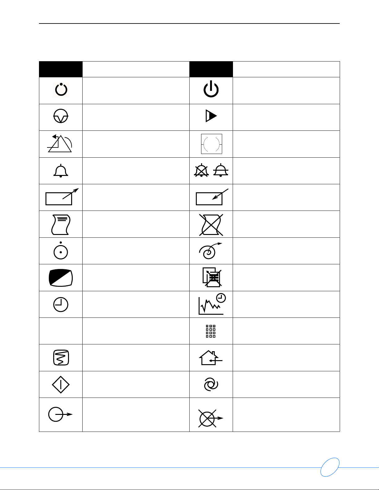
90207 Ambulatory Blood Pressure Monitor Service Manual
Symbol Description Symbol Description
Stand-by STAND-BY Key
PAUSE or INTERRUPT Slow Run
Reset Power Indicator LED
?
Alarm
Temporary Shut Off of Alarm Tone
or Screen Indicators
Indicator — Remote Control Indicator — Local Control
PRINT REPORT Key Indicator — Out of Paper
Partial ON/OFF Recorder Paper
1
2
1
3
Normal Screen Return to Prior Menu
2
3
Clock/Time Setting Key TREND/TIMER Key
HELP (Explain Prior Screen) Key Keypad
Activate Recorder for Graphics Indoor Use Only
START (NIBP) Key Auto Mode (NIBP)
Output No Output (Terminated)
7-2
Page 55

90207 Ambulatory Blood Pressure Monitor Service Manual
Symbol Description Symbol Description
Data Input/Output Input/Output
Input Reset
Menu Keys Waveform/Parameter Keys
Symbols
1
2
3
1
2
3
Monitor Setup
Select Program Options
B
Access Special Function Menu Return Unit to Monitor Mode
1
Serial Port 1 Serial Port 2
External marker push button
connection
Arterial Pulse
1
2
3
1
2
3
A
Set Initial Conditions Menu
2
SDLC
SDLC Port
Electrocardiograph or
Defibrillator Synchronization
Gas Exhaust Foot Switch
Enlarge, Zoom Delete
x
12,200 m
PCMCIA Card Event
Keep Dry Fragile; handle with care
Environmental Shipping/Storage
Altitude Limitations
Environmental Shipping/Storage
Temperature Limitations
This Way Up
Environmental Shipping/Storage
Humidity Limitations
7-3
Page 56
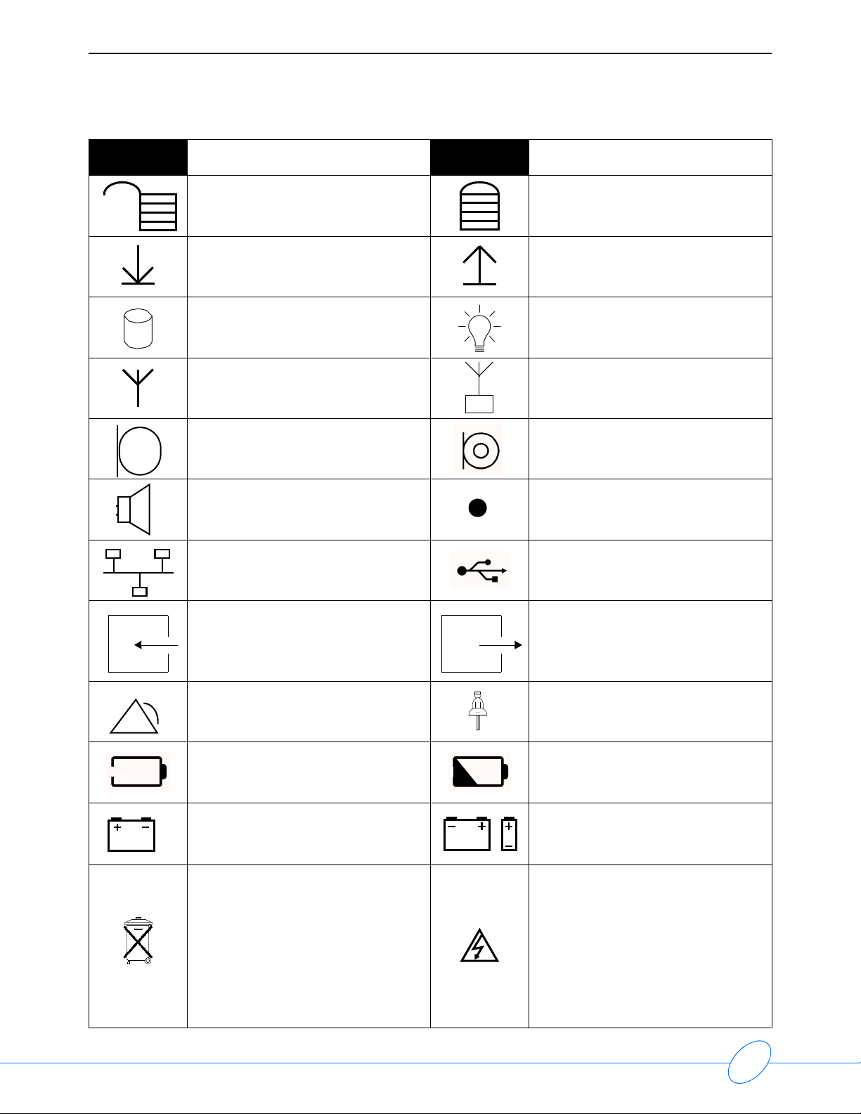
90207 Ambulatory Blood Pressure Monitor Service Manual
Symbol Description Symbol Description
Open Padlock Closed Padlock
Down Arrow Up Arrow
Hard Drive Power Indicator LED
Antenna Mermaid Connector
Microphone Omnidirectional Microphone
Audio Output, Speaker Activate Telemetry Recorder
Network Connection Universal Serial Bus
Gas Sampling Port Gas Return Port
Remote Alarm; Nurse Alert Nurse Call
Battery Status Low Battery
Battery
Replace only with the appropriate
battery.
All batteries should be disposed of
properly to protect the environment.
Lithium batteries should be fully
discharged before disposal.
Batteries such as lead-acid (Pb) and
nickel-cadmium (Ni-Cd) must be
recycled. Please follow your internal
procedures and or local (provincial)
laws regarding disposal or recycling.
Replace only with the appropriate
battery.
(+ / - signs may be reversed)
Caution - hazardous voltages. To
reduce risk of electric shock, do not
remove the cover or back. Refer
servicing to a qualified service
personnel (U.S.A.).
DANGER - High Voltage
(International)
7-4
Page 57
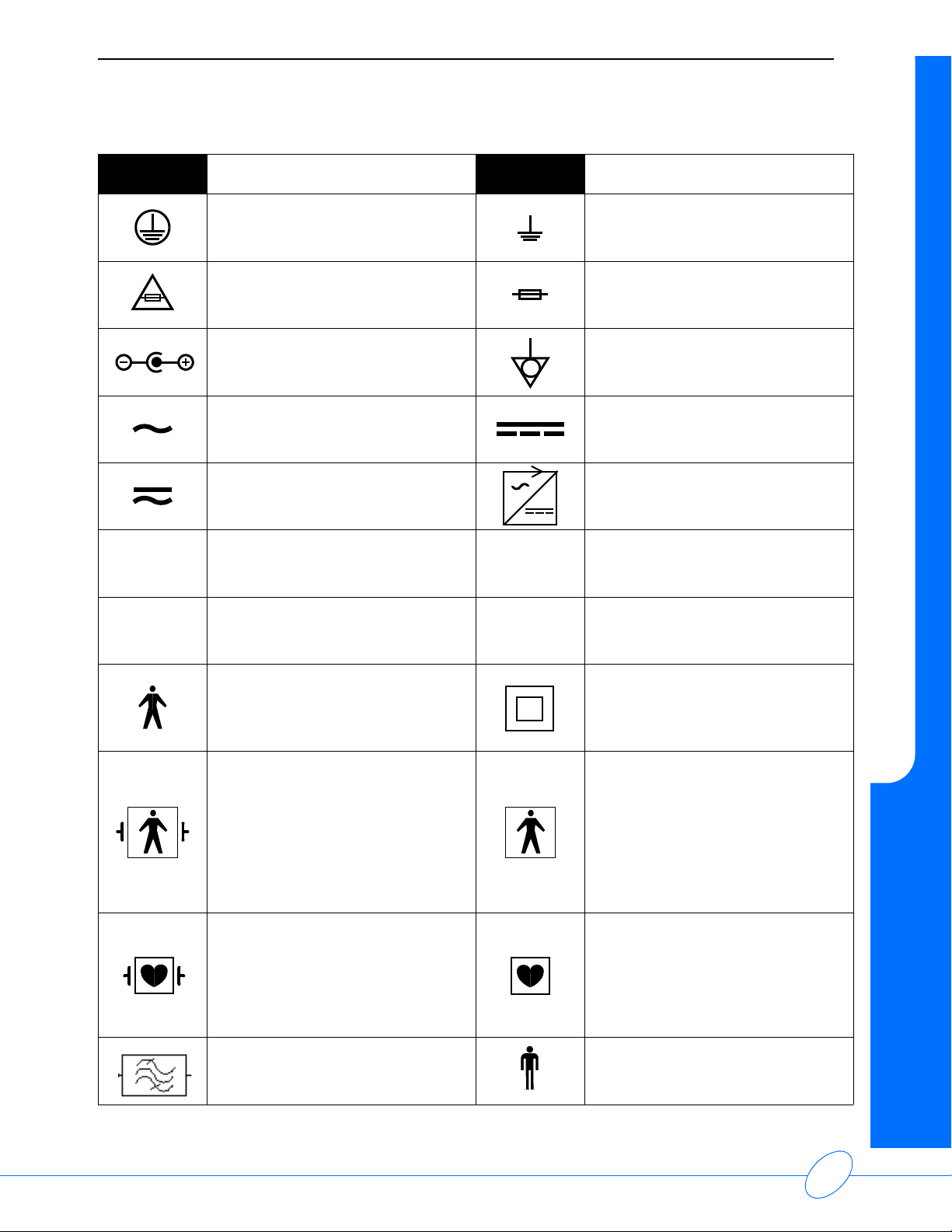
90207 Ambulatory Blood Pressure Monitor Service Manual
Symbol Description Symbol Description
Protective Earth Ground Functional Earth Ground
Replace Fuse Only as Marked Fuse
Symbols
Power supply jack polarity.
(+ / - signs may be reversed)
Alternating Current Direct Current
Both Direct and Alternating Current AC/DC Input
AHz
VW
Amperes Hertz
Volts Watts
IEC 601-1 Type B equipment. The
unit displaying this symbol contains
an adequate degree of protection
against electric shock.
IEC 601-1 Type BF equipment
which is defibrillator-proof. The unit
displaying this symbol contains an
F-type isolated (floating) patientapplied part which contains an
adequate degree of protection
against electric shock, and is
defibrillator-proof.
Equipotentiality Terminal
Class II Equipment
IEC 601-1 Type BF equipment. The
unit displaying this symbol contains
an F-type isolated (floating) patientapplied part providing an adequate
degree of protection against electric
shock.
IEC 601-1 Type CF equipment. The
unit displaying this symbol contains
an F-type isolated (floating) patientapplied part providing a high degree
of protection against electric shock,
and is defibrillator-proof.
Loop Filter Adult NIBP
IEC 601-1 Type CF equipment. The
unit displaying this symbol contains
an F-type isolated (floating) patientapplied part providing a high degree
of protection against electric shock.
7-5
Page 58

90207 Ambulatory Blood Pressure Monitor Service Manual
S
Symbol Description Symbol Description
Note Note
WARNING
ETL Laboratory Approved
®
Canadian Standards Association
Approved
U
Risk of Explosion if Used in the
Presence of Flammable Anesthetics
!
!
Warning About Potential Danger to
Human Beings
Noninvasive Blood Pressure (NIBP),
Neonate
Fetal Monitor Connection
RS232 (Digital)
Happy Face Sad Face
CAUTION
Operates on Non-Harmonized
Radio Frequencies in Europe
Attention - Consult Operations or
Service Manual for Description
Caution About Potential Danger to a
Device
Fetal Monitor Connection (Analog)
Physiological Monitor Connection
RS232 (Digital)
Magnifying Glass Compression
File Cabinet List of Rooms
Arrows Printer
Recycle Service Message
Radio transmitting device; elevated
levels of non-ionizing radiation
7-6
Page 59

90207 Ambulatory Blood Pressure Monitor Service Manual
Abbreviations used as symbols are shown below.
Symbol Description Symbol Description
1 - 32
ANT 1
ANT 2
CH
ch
C.O.
CO
co
ECG
ecg
EMG
emg
Access Codes
1 Through 32
Diversity Antenna System 1
Diversity Antenna System 2
AIR Air
Arr1
ArrNet2
EEG, EMG, or ECG Channel
EEG Channels - CH1, CH2, CH3, CH4
cmH
EMG Channel - CH5
Cardiac Output
Electrocardiogram
DIA
dia
EEG
eeg
Electromyogram ESIS
Arrhythmia Net 1
Arrhythmia Net 2
O Centimeters of Water
2
Diastolic
Electroencephalogram
Electrosurgical Interference
Suppression
Symbols
EXT External FECG Fetal Electrocardiogram
FHR1
FHR2
HLO
hlo
NIBP
nibp
Fetal Heart Rate, Channel 1
Fetal Heart Rate, Channel 2
GND
gnd
Ground
High-Level Output Multiview Multi-Lead Electrocardiogram
Noninvasive Blood Pressure N
O Nitrous Oxide
2
PRESS
O
2
Oxygen
press
Pressure
PRS
RESP
resp
SPO2
SpO2
SpO
SaO
2
2
Respiration SDLC Synchronous Data Link Control
Arterial Oxygen Saturation
as Measured by Pulse Oximetry
SVO2
SvO2
Sv
O
Mixed Venous Oxygen Saturation
2
7-7
Page 60

90207 Ambulatory Blood Pressure Monitor Service Manual
Symbol Description Symbol Description
SYS
sys
TEMP
temp
VAC Vacuum Connection
Systolic
Temperature UA Uterine Activity or Umbilical Artery
T1
T2
T3
T4
Temperature 1
Temperature 2
Temperature 3
Temperature 4
7-8
Page 61

Appendix A — Electromagnetic
Contents
Electromagnetic Emissions . . . . . . . . . . . . . . . . . . . . . . . . . . . . . . . . . . . . . . . . . . . . . 1
Electromagnetic Immunity . . . . . . . . . . . . . . . . . . . . . . . . . . . . . . . . . . . . . . . . . . . . . . 1
Frequency Separation Distances . . . . . . . . . . . . . . . . . . . . . . . . . . . . . . . . . . . . . . . . 2
Electromagnetic Emissions
Note:
The 90207 ABP monitor has been tested under laboratory conditions and is suitable
for use in all establishments, including domestic establishments and those directly
connected to the public low-voltage power supply network that supplies buildings
used for domestic purposes. The customer, or user, of the module should ensure that
it is used in such an environment.
Emission Test Compliance Electromagnetic Environment
Compatibility
RF emissions
CISPR 11
Group 1
Class B
Electromagnetic Immunity
Note:
The ABP monitor is intended for use in the electromagnetic environment specified
below. The customer, or user, of the module should ensure that it is used in such an
environment.
Immunity Test
Electrostatic
discharge (ESD)
IEC 61000-4-2
IEC 60601
Test Level
±6 kV contact
±8 kV air
The ABP monitor uses RF energy only for internal
function. Therefore, RF emissions are very low and
are not likely to cause any interference in nearby
electronic equipment
Compliance
Level
6 kV contact
8 kV air
Electromagnetic Environment
Floors should be wood, concrete, or
ceramic tile. If floors are covered with
synthetic material, the relative
humidity should be at least 30%.
A-1
Page 62

90207 Ambulatory Blood Pressure Monitor Service Manual
Frequency Separation Distances
Note:
The ABP monitor is intended for use in an electromagnetic environment in which
radiated RF disturbances are controlled. The customer, or user, of the module can
help prevent electromagnetic interference by maintaining a minimum distance
between portable and mobile RF communications equipment (transmitters) and the
module, as recommended below, according to the maximum output power of the
communications equipment.
Recommended Separation Distances Between Portable and Mobile RF Communications
Equipment and the Monitor (Always evaluate electronic equipment on site before use.)
Immunity
Tes t
Radiated RF
IEC 61000-4-3
IEC 60601
Test Level
3 V/m
80 MHz to
2.5 GHz
Compliance
Level
3 V/m
1 kHz sine
80% AM
Electromagnetic Environment
Portable and mobile RF communications equipment
should be used no closer to any part of the monitor,
including cables, than the recommended separation
distance calculated from the equation applicable to the
frequency of the transmitter.
Recommended separation distance:
3.5
V
3.5
E
E
P
]
1
P
]
1
7
P
]
1
d =
[
150 kHz to 80 MHz
d =
[
80 MHz to 800 MHz
d =
[
800 MHz to 2.5 GHz
Where P is the maximum output power rating of the
transmitter in watts (W) according to the transmitter
manufacturer, and d is the recommended separation
distance in meters (m).
Field strengths from fixed RF transmitters, as
determined by an electromagnetic site survey,* should
be less than the compliance level in each frequency
range.**
Interference may occur in the vicinity of
equipment marked with the following symbol.
IEC 60417-5140: Non-ionizing
electromagnetic radiation
* Field strengths from fixed transmitters, such as base stations for radio (cellular/cordless) telephones
and land mobile radios, amateur radio, AM and FM radio broadcast, and TV broadcast cannot be
predicted theoretically with accuracy. To assess the electromagnetic environment due to fixed RF
transmitters, an electromagnetic site survey should be considered. If the measured field strength in
the location in which the monitors are used exceeds the applicable RF compliance level above, the
monitors should be observed to verify normal operation. If abnormal performance is observed,
additional measures may be necessary, such as reorienting or relocating the monitors.
** Over the frequency range 150 kHz to 80 MHz, field strengths should be less than [ V1 ] V/m.
A-2
Page 63

90207 Ambulatory Blood Pressure Monitor Service Manual
Appendix A — Electromagnetic Compatibility
Rated Maximum
Output Power of
Tra nsmitter
(watts)
0.01 0.02 0.02 0.04
0.1 0.06 0.06 0.1
1 0.2 0.2 0.4
10 0.6 0.6 1.1
100 1.8 1.8 3.5
Note 1: At 80 MHz and 800 MHz, the separation distance for the higher frequency range applies.
Note 2: These guidelines may not apply in all situations. Electromagnetic propagation is affected by
absorption and reflection from structures, objects, and people.
Separation Distance According to Frequency of Transmitter
(meters)
150 kHz to 80 MHz 80 MHz to 800 MHz 800 MHz to 2.5 GHz
A-3
Page 64

 Loading...