

Southern Pride XLR-1400 Installation Manual
XLR-1400
XLR SERIES
XLR-600 & XLR-1400
INSTRUCTION MANUAL
XLR-600
Distributing, L.L.C.
472 South Mill Street, Alamo, TN 38001
Sales: 800-851-8180
www.southernpride.com - sales@soprid e.com - servic e@sopride.com
Service: 800-437-2679 - Service Fax: 618-993-0378 - parts@sopride.com

CONGRATULATIONS
In selecting Southern Pride, you have chosen the finest, most advanced
and most fully automatic wood burning barbecue pit available.
With us, “ It’s Simply, a Matter of Pride”.
Please read this Instruction Manual carefully prior to installation and operation
of your Southern Pride pit. Proper installation, operation, cleaning and maintenance
are essential for your satisfaction and safe operation.
KEEP THIS MANNUAL FOR REFERENCE
TABLE OF CONTENTS
Safety Information . . . . . . . . . . . . . . . . . . . . . . . . . . . . . . . . . . . . . . . . . . . 3
Diagram of Controls & Components . . . . . . . . . . . . . . . . . . . . . . . . . . . . 4
Electrical Instructions . . . . . . . . . . . . . . . . . . . . . . . . . . . . . . . . . . . . . . . . 6
Burner Specification & Instructions . . . . . . . . . . . . . . . . . . . . . . . . . . . . 7
Gas Piping Instructions . . . . . . . . . . . . . . . . . . . . . . . . . . . . . . . . . . . . . . . 8
Venting Instructions . . . . . . . . . . . . . . . . . . . . . . . . . . . . . . . . . . . . . . . . . 9
Cold Weather Operations . . . . . . . . . . . . . . . . . . . . . . . . . . . . . . . . . . . . . 11
Operating Instructions . . . . . . . . . . . . . . . . . . . . . . . . . . . . . . . . . . . . . . . 12
Cleaning Instructions . . . . . . . . . . . . . . . . . . . . . . . . . . . . . . . . . . . . . . . . 16
Maintenance Schedule . . . . . . . . . . . . . . . . . . . . . . . . . . . . . . . . . . . . . . . . 17
Wiring Diagrams . . . . . . . . . . . . . . . . . . . . . . . . . . . . . . . . . . . . . . . . . . . . 20
Replacement Parts List . . . . . . . . . . . . . . . . . . . . . . . . . . . . . . . . . . . . . . . 21
Warranty . . . . . . . . . . . . . . . . . . . . . . . . . . . . . . . . . . . . . . . . . . . . . . . . . . 22
2

SAFETY INFORMATION
FOR YOUR SAFETY
IF YOU SMELL GAS . . .
1. Open windows.
2. Do not touch electrical switches.
3. Extinguish any open flames.
4. Immediately call your gas supplier.
DO NOT STORE OR USE GASOLINE OR OTHER FLAMMABLE VAPORS OR
LIQUIDS IN THE VICINITY OF THIS OR ANY OTHER APPLIANCES.
1. The pit area MUST be kept clear and free of combustible materials, gasoline and
other flammable vapors and liquids.
2. The flow of combustion and ventilating air MUST NOT be obstructed from reaching
the pit.
3. The frame of the unit MUST be electrically grounded at all times. See “Electrical
Instructions”.
4. Caution should be used when opening and closing the Firebox Door. The door is HOT
during operation.
5. DO NOT remove service compartment access panels when unit is in operation or leave
off during operation.
6. Gas burners require the services of an experienced Service Technician for proper setting
and adjustment. If the burner does not appear to be operating properly, DO NOT
ATTEMPT TO ADJUST THE BURNER YOURSELF, but call in a competent
serviceman or contact Southern Pride.
7. DO NOT allow unqualified personnel to perform service work or adjustments on
this unit. To do so will VOID WARRANTY and could result in a hazardous condition.
8. Be sure any new employees, who might operate the unit, are instructed on operation and
safety information prior to operating the unit.
9. Caution: Ashes removed from the Firebox should be stored in a non-combustible
container with a sealed lid only. Store ashes in a well ventilated area. FUMES COULD
BE HAZARDOUS.
10. W ARNING : IT IS EXTREMELY IMPORTANT TO FOLLOW DAILY CLEANING
INSTRUCTIONS. BUILDUP OF GREASE OR SOLIDS INSIDE THE PIT COULD
RESULT IN A FIRE HAZARD.
11. KEEP THIS INSTRUCTION MANUAL FOR REFERENCE.
3
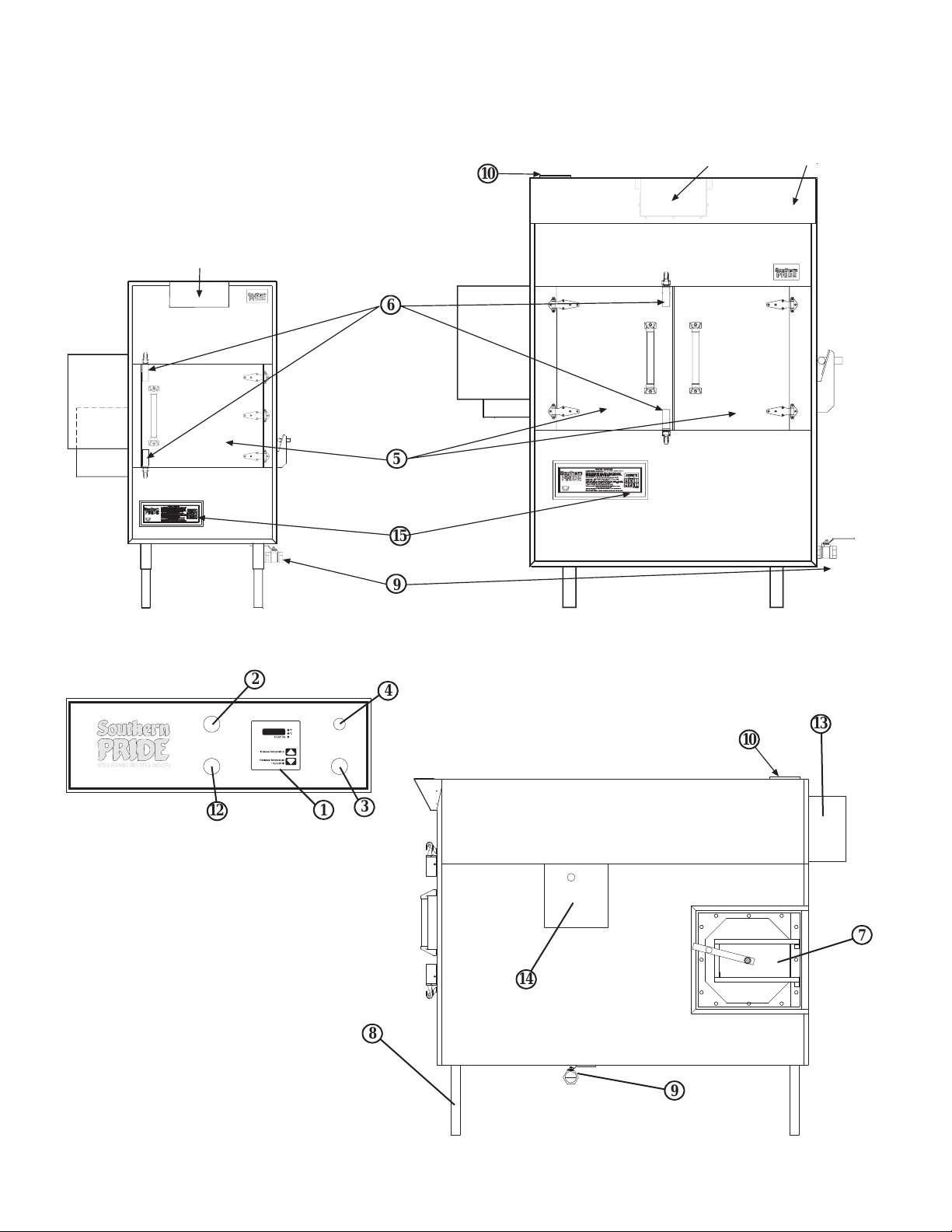
Optional Front Flue
SOUTHERN PRIDE’S
XLR-SERIES BBQ OVENS
10
6
5
15
Front Flue
Heat Shield
2
O
F
N
F
O
M
R
A
E
I
N
W
P
O
E
I
A
R
D
E
V
S
A
S
N
I
T
C
O
E
R
12
STANDARD CONTROLS
9
4
C
R
I
R
E
C
K
U
A
I
E
T
R
B
T
X
R
E
A
E
C
K
T
O
O
R
M
S
3
1
10
13
7
14
8
9
4

XLR Series
CONTROLS AND COMPONENTS
1 . CONTROL THERMOSTAT - Adjustable temperature setting (140-325° F) with OFF position.
Maintains desired Pit temperature by controlling the Gas Burner. Also displays the actual temperature
inside the oven during the cooking cycle.
2. MAIN POWER SWITCH - Activates the Rotisserie, Convection Fan, Thermostat, and Red
Indicator Lamp. (The Red Indicator Lamp on the Main Power Switch indicates when the switch
is ON.)
3. SMOKE EXTRACTOR SWITCH - Activates Smoke Extractor Damper, Exhaust
Fan, and Blue Indicator Lamp. (The Blue Indicator Lamp on the Smoke Extractor Switch indicates
when the switch is ON.) At the same time it de-activates the Burner and Red Indicator Lamp.
4. CIRCUIT BREAKER - Provides protection for the Rotisserie Drive Motor.
5. MEAT LOADING DOORS - For access to Racks and Pit interior.
6. MEAT LOADING DOOR LATCHES - Latches apply positive pressure and seal doors.
7. FIREBOX DOOR - Provides access for loading wood in the Firebox Chamber.
8. CABINET LEGS - Provide adjustment for leveling of the unit.
9. DRAIN VALVE - Is opened after each cooking to drain grease.
10. FLUE COLLAR - For connection of 6” Flue.
11. OPTIONAL SMOKE EXTRACTOR DAMPER - Closes to hold smoke inside pit while
cooking and opens for Exhaust Fan to remove smoke when Smoke Extractor Switch is ON or
when the Meat Loading Doors are Open.
12. ROTISSERIE ADVANCE SWITCH - Momentarily activates Rotisserie to advance the food
racks for loading and unloading when the Meat Door is open, or the Main Power switch is OFF.
13. CONVECTION FAN - Provides air flow inside the Oven for even cooking.
14. BEARING COVER - Provides access for greasing Bearing.
15. DIGITAL CONTROL (Optional) - Provides precise control of the oven and adds special
features, such as a Hold Mode, Automatic Cool Down prior to advancing into the Hold Mode
and an Audible Alarm that sounds when the Cook Cycle is complete or when the control
advances to the Hold Mode.
5
ELECTRICAL INSTRUCTIONS
ELECTRICAL REQUIREMENTS:
120 Volts A.C., 60 hz.,
2 wire, single phase,
15 amp wiring required.
WARNING:
CHASSIS MUST BE GROUNDED TO
PREVENT POSSIBLE SHOCK HAZARD.
DO NOT ASSUME A PLUMBING LINE
WILL PROVIDE SUCH A GROUND.
WARRANTY IS VOID IF UNIT IS CONNECTED TO ANY VOLTAGE OTHER THAN
SPECIFIED ABOVE AND ON NAMEPLATE.
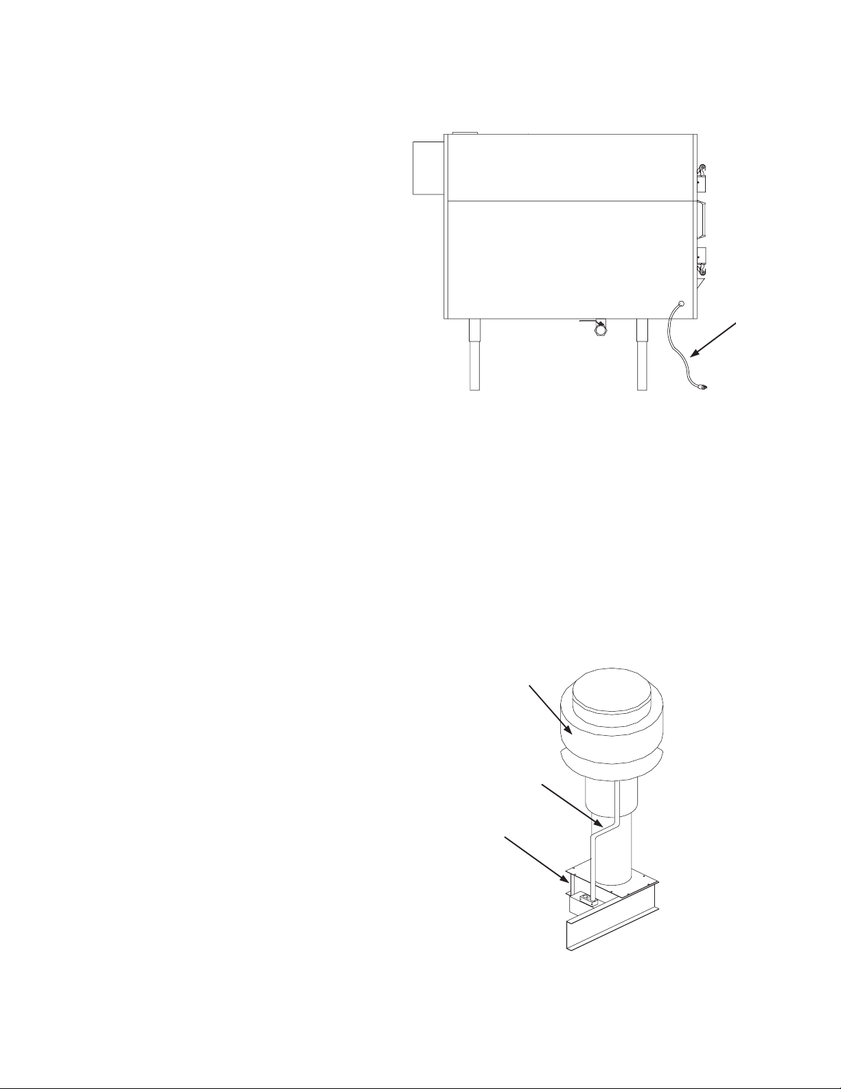
Power
cord
1. Electrician must provide the conduit and wire for hookup.
2. Power is to be left OFF throughout installation.
3. Electrical Service is connected via the factory supplied power cord located on the left front
corner of the oven.
4. On models with optional Smoke Extractor,
electrician must provide conduit and wire
EXHAUST
FAN
for hookup from Junction Box above the
Smoke Extractor Motor on the top of the
pit to the Exhaust fan. Make electrical
connections inside the Junction box.
NOTE: THIS IS NOT A POWER SUPPLY
CONNECTION. IT IS FOR A FAN
CONNECTION ONLY.
CONDUIT
SMOKE
EXTRACTOR
NOTE: 125 V.A.C., 1/4 hp
maximum connected load,
1100 cfm fan rating recom mended.
5. If venting or gas connections are to be
done later, be sure that power is OFF.
6
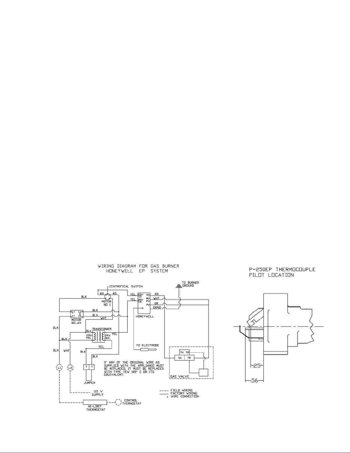
BURNER SPECIFICATIONS
Burner Model: Wayne P250-EP
Firing Capacity: Maximum Input
100,000 BTU/HR on Model XLR-600
125,000 BTU/HR on Model XLR-1400
150,000 BTU/HR on Model XLR-1400 with 18” Racks
Fuels: Natural and L.P. Gases
Electrical: 120 V.A.C., 60 hz, 1 ph
Orifice Sizes: XLR-600 XLR-1400
Natural Gas #5 #1 #5
L.P. Gas 1/8” #29 1/8”
NOTE: Orifice and valve setting must correlate with type of gas being supplied.
Gas Supply Line Pressure: Natural - 4.5” W.C. Minimum L.P. - 11.0” W.C. Minimum
10.0” W.C Maximum 13.0” W.C. Maximum
MANIFOLD PRESSURE: Natural - 3.5” W.C. L.P. - 10.0” W.C.
GAS VALVE: Control Knob must be ON.
(150,000 BTU)
XLR-1400
(125,000 BTU)
7
 Loading...