


Owner’s Manual
IMPORTANT FOR FUTURE REFERENCE
Please complete this information and retain this manual for the life of the equipment:
Model #: ___________________________
Serial #: ___________________________
Date Purchased: _____________________
Radiant Broilers
|
P32D-3240 |
234R |
 WARNING
Improper installation, adjustment, alteration, service or maintenance can cause property damage, injury or death. Read the installation, operating and maintenance instructions thoroughly before installing or servicing this equipment.
1100 Old Honeycutt Road Fuquay-Varina, North Carolina 27526 USA www.southbendnc.com
MANUAL 1199797 REV 0 (6/14) $21.00
RADIANT BROILER MANUAL SECTION BR

SAFETY PRECAUTIONS |
RADIANT BROILER |
SAFETY PRECAUTIONS
Before installing and operating this equipment, be sure everyone involved in its operation is fully trained and aware of precautions. Accidents and problems can be caused by failure to follow fundamental rules and precautions.
The following symbols, found throughout this manual, alert you to potentially dangerous conditions to the operator, service personnel, or to the equipment.

 DANGER This symbol warns of immediate hazards that will result in severe injury or death.

 WARNING This symbol refers to a potential hazard or unsafe practice that could result in injury or death.

 CAUTION
NOTICE
This symbol refers to a potential hazard or unsafe practice that could result in injury, product damage, or property damage.
This symbol refers to information that needs special attention or must be fully understood, even though not dangerous.
 WARNING
FIRE HAZARD
FOR YOUR SAFETY
Do not store or use gasoline or other flammable vapors and liquids in the vicinity of this or any other appliance.
Keep area around cooking appliances free and clear of combustibles.
Purchaser of equipment must post in a prominent location detailed instructions to be followed in the event the operator smells gas. Obtain the instructions from the local gas supplier.
 WARNING
BURN HAZARD
Contact with hot surfaces will cause severe burns. Always use caution when operating cooking appliances.
 WARNING
EXPLOSION AND ASPHYXIATION HAZARD
In the event a gas odor is detected, shut down equipment at the main gas shut-off valve and immediately call the emergency phone number of your gas supplier.
Improper ventilation can result in headaches, drowsiness, nausea, and could result in death. Do not obstruct the flow of combustion and ventilation air to and from cooking appliances.
 WARNING
ELECTRIC SHOCK HAZARD
For appliances that use electric power, disconnect the power to the appliance before cleaning. Do not remove panels that require tools to remove. Disconnect power before opening kick panel below oven.
NOTICE
This appliance is intended for commercial use, and is only for professional use. It shall be used by trained, qualified people.
Warranty will be void if service work is performed by other than a qualified technician, or if other than genuine
Southbend replacement parts are installed.
Give this Owner’s Manual and important papers to the proper authority to retain for future reference.
Copyright © 2014 by Southbend. All rights reserved. Published in the United States of America.
PAGE 2 OF 40 |
OWNER’S MANUAL 1199797 REV 0 (6/14) |

RADIANT BROILER |
INTRODUCTION |
Congratulations! You have purchased one of the finest pieces of heavy-duty commercial cooking equipment on the market.
You will find that your new equipment, like all Southbend equipment, has been designed and manufactured to meet the toughest standards in the industry. Each piece of Southbend equipment is carefully engineered and designs are verified through laboratory tests and field installations. With proper care and field maintenance, you will experience years of reliable, trouble-free operation. For best results, read this manual carefully.
RETAIN THIS MANUAL FOR FUTURE REFERENCE. |
|
Table of Contents |
|
Specifications ......................................................................................................................................... |
5 |
Installation .............................................................................................................................................. |
9 |
Operation ............................................................................................................................................... |
15 |
Cleaning ................................................................................................................................................. |
21 |
Adjustments ........................................................................................................................................... |
23 |
Troubleshooting ..................................................................................................................................... |
27 |
Read these instructions carefully before attempting installation. Installation and initial startup should be performed by a qualified installer. Unless the installation instructions for this product are followed by a qualified service technician (a
person experienced in and knowledgeable with the installation of commercial gas an/or electric cooking equipment) then the terms and conditions on the Manufacturer’s Limited Warranty will be rendered void and no warranty of any kind shall apply.
In the event you have questions concerning the installation, use, care, or service of the product, contact:
Southbend
1100 Old Honeycutt Road
Fuquay-Varina, North Carolina 27526 USA
The serial plate is located on the interior side of the lower front panel, as shown below.
OWNER’S MANUAL 1199797 REV 0 (6/14) |
PAGE 3 OF 40 |
INTRODUCTION |
RADIANT BROILER |
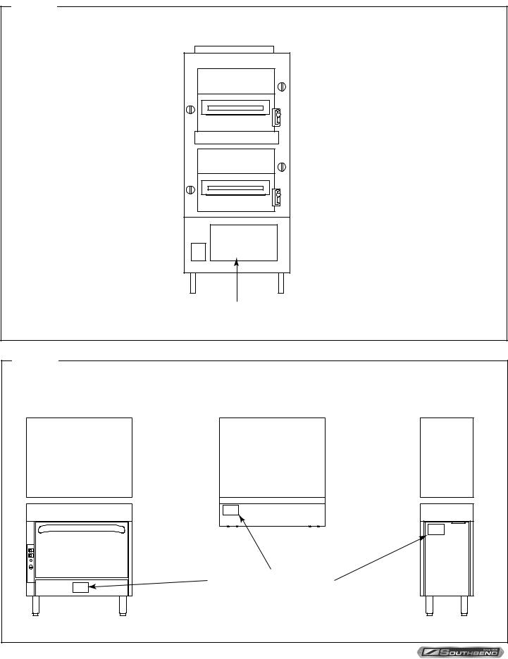
The serial plate is located on the interior side of the lower front panel, as shown below.
Figure 1
Broiler Serial Plate Location
The serial plate is located behind the access panel.
To remove the panel, lift it straight up and pull it out at the bottom.
Figure 2 |
|
Oven Serial Plate Locations |
|
|
Location of Serial Plate |
PAGE 4 OF 40 |
OWNER’S MANUAL 1199797 REV 0 (6/14) |

RADIANT BROILER |
SPECIFICATIONS |
SPECIFICATIONS
NOTICE
Local codes regarding installation vary greatly from one area to another. The National Fire Protection Association, Inc. states in its NFPA 96 latest edition that local codes are the “authority having jurisdiction” when it comes to installation requirements for equipment. Therefore, installations should comply with all local codes.
Southbend reserves the right to change specifications and product design without notice. Such revisions do not entitle the buyer to corresponding changes, additions, or replacements for previously purchased equipment.
This product is intended for commercial use only, not for household use.
The installation must conform with local codes, or in the absence of local codes, with the National Fuel Gas Code, ANSI Z223.1, Natural Gas Installation Code, CAN/CGA-B149.1, or the Propane Installation Code CAN/CGA-B149.2, as applicable, including:
1.The appliance and its individual shutoff valve must be disconnected from the gas supply piping system during any pressure testing of that system at test pressures in excess of 1/2 psi (3.45 kPa).
2.The appliance must be isolated from the gas supply piping system by closing its individual manual shutoff valve ` during any pressure testing of the gas supply piping system at test pressures equal to or less than 1/2 psi (3.45 kPa).
CLEARANCES
 WARNING
MINIMUM CLEARANCES FROM COMBUSTIBLE CONSTRUCTION
Minimum clearance from combustible surfaces is 6” on the sides and back. Minimum clearance from non-combustible surfaces is 0” on the sides and back.
Adequate clearance must be provided in the aisle in front of the broiler to permit operation (including pulling out of broiler racks and removal of the drippings drawers), as well as for servicing. No additional clearance is required for servicing as the broiler is serviceable from the front.
The high-temperature flue products flow out through the top of the broiler. Installation under a vented hood is recommended.
Units have 6” legs or casters, and may be installed on combustible floors.
VENTILATION
 WARNING
Improper ventilation can result in personal injury or death. Ventilation which fails to properly remove flue products can cause headaches, drowsiness, nausea, or could result in death.
All units must be installed in such a manner that the flow of combustion and ventilation air is not obstructed. Provisions for adequate air supply must be provided. Do not obstruct the front of the unit at the bottom where the air filter is located or below the oven door as combustion air enters at these locations.
OWNER’S MANUAL 1199797 REV 0 (6/14) |
PAGE 5 OF 40 |

SPECIFICATIONS |
RADIANT BROILER |
NOTICE
Proper ventilation is the owner’s responsibility. Any problem due to improper ventilation will not be covered by the warranty.
Be sure to inspect and clean the ventilation system according to the ventilation equipment manufacturer’s instructions.
If a ventilation canopy is used, it is recommended that the canopy extend 152.4 mm (6”), past the appliance and that the bottom edge be located 1981 mm (6’6”) from the floor. Filters should be installed at an angle of 45° or more from the horizontal. This position prevents dripping grease and facilitates collecting the run-off grease in a drip pan, unusually installed with a filter.
A strong exhaust fan tends to create a vacuum in the room and may interfere with burner performance or may extinguish pilot flames. Fresh air openings approximately equal to the fan area will relieve such a vacuum. The exhaust fan should be installed at least 609.6 mm (24”), above the vent opening at the top of the unit.
NOTICE
Due to the variety of problems encountered by outside weather conditions, venting by canopies or wall fans is preferred over any type of direct venting.
If the unit is connected directly to an outside flue, a CSA design certified down draft diverter must be installed.
In case of unsatisfactory performance on any appliance, check the appliance with the exhaust fan turned OFF. Do this only long enough to check whether doing so corrects any problems with equipment performance. Then turn the exhaust fan back on and let it run to remove any exhaust that may have accumulated during the test.
FREE STANDING BROILERS
GAS SUPPLY
The broiler is design-certified for operation on natural or propane gases. The broiler is shipped configured and adjusted for the type of gas specified by the purchaser, which is indicated on the serial plate (see Figure 1). Connect the broiler ONLY to the type of gas for which it is configured and adjusted.
The broiler has a 3/4” rear gas connection with a male NPT connector and an internal shut-off valve. Minimum supply pressure is 7” W.C. for natural gas, 11” W.C. for propane. The broiler has an internal pressure regulator that is set for 4”
W.C. pressure for natural gas or 10” W.C. pressure for propane gas. If using a flexible-hose gas connection, the inside diameter of the hose must not be smaller than the connector on the broiler, and must comply with ANSI Z21.69 (or CSA 6.16). Provide an adequate means of restraint to prevent undue strain on the gas connection.
If applicable, the vent line from the gas appliance pressure regulator shall be installed to the outdoors in accordance with local codes, or in the absence of local codes, with the National Fuel Gas Code, ANSI Z223.1/NFPA 54 or the Natural Gas and Propane Installation Code CSA B149.1, as applicable.
An adequate gas supply is imperative. Undersized or low pressure lines will restrict the volume of gas required for satisfactory performance. Fluctuations of more than 25% on natural gas or 10% on propane gas will create problems and affect burner operating characteristics. A 1/8” pressure tap is located adjacent to the pressure regulator to measure the pressure. The supply line to the broiler should have an inside diameter no smaller than 3/4”.
PAGE 6 OF 40 |
OWNER’S MANUAL 1199797 REV 0 (6/14) |

RADIANT BROILER |
SPECIFICATIONS |
OVEN BASE BROILER
ELECTRICITY SUPPLY
Broilers with convection-oven bases with optional electronic ignition require electric power (50Hz or 60Hz single-phase AC). 120V models have a 7-foot (2134 mm) power cord with a grounded plug (1.0 amps for “D” Models and 4.8 amps for “A” Models). The 208/240V models have a terminal block for connection to a single-phase 208/240V source (1.0 amps for “D” Models and 2.6 amps for the “A” Models).
The appliance, when installed, must be electrically grounded in accordance with local codes, or in the absence of local codes, with the National Electrical Code, ANSI/NFPA 70, or the Canadian Electrical Code, CSA C22.2, as applicable. An electrical diagram is located on the rear of the oven, near the motor.
GAS SUPPLY
Southbend cooking equipment is design-certified for operation on natural or propane gases. Southbend cooking equipment is shipped configured and adjusted for the type of gas specified by the purchaser, which is indicated on the serial plate (see Figure 1 and Figure 2). Connect the Southbend cooking equipment ONLY to the type of gas for which it is configured and adjusted.
Oven base broiler has a 1-1/4” front gas manifold that can be coupled to adjacent section(s). Sections can be ordered with an optional 1” rear gas connection with a male NPT connector. Minimum supply pressure is 17.436 mbar (7” W.C.) for natural gas, 27.4 mbar (11” W.C.) for propane. An external pressure regulator and shut off valve must be provided. If using a flexible-hose gas connection, the I.D. of the hose must not be smaller than the connector on the unit and must comply with ANSI Z21.69. Provide an adequate means of restraint to prevent undue strain on the gas connection.
If applicable, the vent line from the gas appliance pressure regulator shall be installed to the outdoors in accordance with local codes, or in the absence of local codes, with the National Fuel Gas Code, ANSI Z223.1, Natural Gas Installation Code, CAN/CGA-B149.1, or the Propane Installation Code CAN/CGA-B149.2, as applicable.
An adequate gas supply is imperative. Undersized or low pressure lines will restrict the volume of gas required for satisfactory performance. Fluctuations of more than 25% on natural gas or 10% on propane gas will create problems and affect burner operating characteristics. A 1/8” pressure tap is located on the manifold to measure the manifold pressure.
The supply line to the sectional unit should be no smaller than the inside diameter of the pipe on the equipment to which it is connected.
To ensure optimum unit operation the pressure in the main supply line, when all units are operating simultaneously, should not drop below 17.436 mbar (7” W.C.) for natural gas and 27.4 mbar (11” W.C.) for propane gas.
OWNER’S MANUAL 1199797 REV 0 (6/14) |
PAGE 7 OF 40 |

SPECIFICATIONS |
RADIANT BROILER |
Figure 3 |
|
Free Standing Broiler Preasure Tap Location |
|
|
1/8" NPT |
|
Pressure Tap |
Figure 4 |
|
Oven Base Broilers Pressure Tap Locations |
|
|
1/8" NPT |
|
PRESSURE TAP |
|
1/8" NPT |
|
PRESSURE TAP |
PAGE 8 OF 40 |
OWNER’S MANUAL 1199797 REV 0 (6/14) |

RADIANT BROILER |
INSTALLATION |
INSTALLATION
NOTICE
These installation procedures must be followed by qualified personnel or warranty will be void.
Local codes regarding installation vary greatly from one area to another. The National Fire Protection Association, Inc. states in its NFPA 96 latest edition that local codes are the “authority having jurisdiction” when it comes to installation requirements for equipment. Therefore, installations should comply with all local codes.
The installation must conform with local codes, or in the absence of local codes, with the National Fuel Gas Code, ANSI Z223.1, Natural Gas Installation Code, CAN/CGA-B149.1, or the Propane Installation Code CAN/CGA-B149.2, as applicable, including:
1.The appliance and its individual shutoff valve must be disconnected from the gas supply piping system during any pressure testing of that system at test pressures in excess of 1/2 psi (3.45 kPa) or 35 mbar (14” W.C).
2.The appliance must be isolated from the gas supply piping system by closing its individual manual shutoff valve during any pressure testing of the gas supply piping system at test pressures equal to or less than 1/2 psi (3.45 kPa) 35 mbar (14” W.C).
NOTICE
EXHAUST FANS AND CANOPIES: It is recommended that the Southbend equipment be installed under a ventilation hood. Consult local codes for proper installation of hoods. Proper ventilation is the owner’s responsibility. Any problem due to improper ventilation will not be covered by warranty.
NOTICE
In the Commonwealth of Massachusetts all gas appliances vented by either mechanical systems or ventilation hoods shall comply with 248 CMR interlocking requirements.
STEP 1: UNPACKING
IMMEDIATELY INSPECT FOR SHIPPING DAMAGE
All containers should be examined for damage before and during unloading. The freight carrier has assumed responsibility for its safe transit and delivery. If damaged equipment is received, either apparent or concealed, a claim must be made with the delivering carrier.
Apparent damage or loss must be noted on the freight bill at the time of delivery. The freight bill must then be signed by the carrier representative (Driver). If the bill is not signed, the carrier may refuse the claim. The carrier can supply the necessary forms.
A request for inspection must be made to the carrier within 15 days if there is concealed damage or loss that is not apparent until after the equipment is uncrated. The carrier should arrange an inspection. Be certain to hold all contents plus all packing material.
For each section, do the following:
1.Cut the banding straps and remove the corrugated cardboard surrounding the Southbend product. Do not remove any tags or labels attached to the equipment until the unit is installed and working properly.
2.Cut the banding strap holding the equipment to the wooden skid.
3.Unbolt the shipping hold-down brackets from the skid, then remove the brackets from the appliance.
4.If the equipment is to be installed on 6” legs, go to Step 2a.
If the equipment is to be installed on 6” casters, go to Step 2b.
OWNER’S MANUAL 1199797 REV 0 (6/14) |
PAGE 9 OF 40 |

INSTALLATION |
RADIANT BROILER |
STEP 2A: ATTACH LEGS
A set of four legs is packed with equipment ordered with legs. (For units ordered with casters, go to Step 2b.)
1.Raise equipment sufficiently to allow legs to be attached. For safety, “shore up” and support the equipment with an adequate blocking arrangement strong enough to support the load.
2.Screw the legs into the leg pad holes, located on bottom at each corner. The legs should be fully screwed into the leg pads.
3.Lower unit gently onto a level surface. Never drop or allow the unit to fall.
4.Go on to Installation Step 3.
Figure 5 |
Installation of Legs |
STEP 2B: ATTACH CASTERS
NOTICE
For an appliance equipped with casters, (1) the installation shall be made with a connector that complies with the
Standard for Connectors for Movable Gas Appliances, ANSI Z21.69 or Connectors for Moveable Gas Appliances, CAN/CGA-6.16, and a quick-disconnect device that complies with the Standard for Quick-Disconnect Devices for Use With Gas Fuel, ANSI Z21.41, or Quick Disconnect Devices for Use with Gas Fuel, CAN1-6.9, (2) adequate means must be provided to limit the movement of the appliance without depending on the connector and the quickdisconnect device or its associated piping to limit the appliance movement, and (3) the restraining means should be attached to a frame member on the back of the unit.
A set of four casters is packed with equipment ordered with casters (instead of legs).
A threaded leg pad is fastened to the base frame at each corner. Each caster has a corresponding mating thread. The casters can be adjusted to overcome a slightly uneven floor. Casters are provided with a fitting for proper lubrication when required.
1.Raise unit sufficiently to allow the casters to be attached. For safety, “shore up” and support the unit with an adequate blocking arrangement strong enough to support the load.
2.Screw the casters into the holes in the centers of the leg pads. Install the casters that have a locking brake under the front of the unit.
3.Lower the unit gently onto a level surface. Never drop or allow the unit to fall.
4.Go to Installation Step 3.
PAGE 10 OF 40 |
OWNER’S MANUAL 1199797 REV 0 (6/14) |
RADIANT BROILER |
INSTALLATION |
Figure 6 |
|
Installation of Casters |
|
STEP 3: ATTACH RESTRAINT |
|
NOTICE
For an appliance equipped with casters, (1) the installation shall be made with a connector that complies with the
Standard for Connectors for Movable Gas Appliances, ANSI Z21.69 or Connectors for Moveable Gas Appliances, CAN/CGA-6.16, and a quick-disconnect device that complies with the Standard for Quick-Disconnect Devices for Use With Gas Fuel, ANSI Z21.41, or Quick Disconnect Devices for Use with Gas Fuel, CAN1-6.9, (2) adequate means must be provided to limit the movement of the appliance without depending on the connector and the quickdisconnect device or its associated piping to limit the appliance movement, and (3) the restraining means should be attached to a frame member on the back of the unit.
Install the restraint cable to an appliance mounted on casters using the following procedure:
1.Secure the restraining device bracket (item “B” in the following illustration) to a wall stud located as close as possible to the appliance connector inlet and outlet connections. Use four #12 screws (item “C”) and plastic anchors (item “A”) if necessary.
2.Install eye-bolt (item “F”) to a frame member on the rear of the equipment. After checking carefully behind the frame member for adequate clearance, drill a 1/4” hole through the frame member.
3.Thread hex nut (item “G”) and slide the washer (item “H”) onto the eye-bolt. Insert the eye-bolt through the 1/4” drilled hole and secure with a washer (item “H”) and nylon lock nut (item “I”).
4.Using the spring-loaded snap hooks, attach the restraining device to the bracket and the eye-bolt.
5.Using the cable clamp (item “D”), adjust the restraining device extended length to prevent over-bending or kinking of the appliance connector.
OWNER’S MANUAL 1199797 REV 0 (6/14) |
PAGE 11 OF 40 |

INSTALLATION |
|
|
RADIANT BROILER |
Figure 7 |
|
|
|
Installation of Restraint |
|
|
|
|
|
C |
A |
|
|
|
|
|
|
|
B |
H |
G |
F |
|
I |
|
|
|
|
|
|
E |
|
|
|
D |
Be sure all controls are turned off prior to disconnecting. After reconnecting, be sure all controls are turned off and all pilots are lit.
NOTICE
Adequate means must be provided to limit the movement of the appliance without depending on the connector and the quick-disconnect device or its associated piping to limit the appliance movement.
The restraining means should be attached to a frame member on the back of the unit.
STEP 3: INSTALL BROILER CERAMICS
The broiler ceramic tiles must be installed before operating the broiler. Do the following for each of the two broiler compartments:
1.Locate and unwrap 20 of the 40 ceramic tiles shipped with the broiler.
2.Lift the front of the burner baffle up, then pull the baffle forward and out of the broiler.
3.Position the ceramic tiles on both sides of both burners. The tile edges will rest on burner lips and side supports. Be certain tiles are installed with cone-shaped projections pointing downward.
4.Replace the burner baffle.
PAGE 12 OF 40 |
OWNER’S MANUAL 1199797 REV 0 (6/14) |
 Loading...