


 Loading...
Southbend 424E, 436A, 436A-1GL, 436D-1GL, 436A-2GL General Manual
...IMPORTANT FOR FUTURE REFERENCE
Please complete this information and retain this manual for the life of the equipment:
Model #: ___________________________
Serial #: ___________________________
Date Purchased: ____________________
OPERATOR’S MANUAL
FOR MODEL 400
RESTAURANT RANGES
With Serial Numbers Beginning 99A
Ranges with Single Oven Base: 424E,
436A, 436A-1GL, 436A-2GL, 436A-2TL, 436A-2GR, 436A-2TR, 436A-3G, 436A-3T
436D, 436D-1GL, 436D-2GL, 436D-2TL, 436D-2GR, 436D-2TR, 436D-3G, 436D-3T
Model 436D
Ranges with Double Oven Base:
448EE, 448EE-2GL, 448EE-2TL, 448EE-2GR, 448EE-2TR 460AA, 460AA-2GL, 460AA-2TL, 460AA-2GR, 460AA-2TR, 460AA-3GL, 460AA-3TL, 460AA-3GR, 460AA-3TR, 460AD, 460AD-2GL, 460AD-2TL, 460AD-2GR, 460AD-2TR, 460AD-3GL, 460AD-3TL, 460AD-3GR, 460AD-3TR,
460DD, 460DD-2GL, 460DD-2TL, 460DD-2GR, 460DD-2TR, 460DD-3GL, 460DD-3TL, 460DD-3GR, 460DD-3TR
Ranges with Double Oven Base and Raised Griddle/Broiler: 460AA-2RR, 460AD-2RR, 460DD-2RR
Model 460AA-2RR
! WARNING
Improper installation, adjustment, alteration, service or maintenance can cause property damage, injury or death. Read the installation, operating and maintenance instructions thoroughly before installing or servicing this equipment.
1100 Old Honeycutt Road, Fuquay-Varina, NC 27526
(800) 348-2558 or (919) 552-9161 • FAX (800) 348-2558 or (919) 552-9798
MANUAL 1182299 REV 1 |
RESTAURANT RANGE |
|
MANUAL SECTION RR |
||
$18.00 |
||
|
MODEL 400 RESTAURANT RANGES
SAFETY PRECAUTIONS
Before installing and operating this equipment, be sure everyone involved in its operation is fully trained and aware of precautions. Accidents and problems can be caused by failure to follow fundamental rules and precautions.
The following symbols, found throughout this manual, alert you to potentially dangerous conditions to the operator, service personnel, or to the equipment.
!DANGER
!WARNING
!CAUTION
NOTICE
This symbol warns of immediate hazards which will result in severe injury or death.
This symbol refers to a potential hazard or unsafe practice which could result in injury or death.
This symbol refers to a potential hazard or unsafe practice which could result in injury, product damage, or property damage.
This symbol refers to information that needs special attention or must be fully understood, even though not dangerous.
! WARNING
FIRE HAZARD
FOR YOUR SAFETY
Do not store or use gasoline or other flammable vapors and liquids in the vicinity of this or any other appliance.
Keep area around appliances free and clear of combustibles.
Purchaser of equipment must post in a prominent location, detailed instructions to be followed in the event the operator smells gas. Obtain the instructions from the local gas supplier.
!WARNING
Asphyxiation can result from improper ventilation. Do not obstruct the flow of combustion and ventilation air to and from your cooking equipment.
NOTICE
Be sure this Operator’s Manual and important papers are given to the proper authority to retain for future reference.
PAGE 2 |
OPERATOR’S MANUAL 1182299 REV 1 |
MODEL 400 RESTAURANT RANGES |
TABLE OF CONTENTS |
Congratulations! You have purchased one of the finest pieces of heavy-duty commercial cooking equipment on the market.
You will find that your new equipment, like all Southbend equipment, has been designed and manufactured to meet the toughest standards in the industry. Each piece of Southbend equipment is carefully engineered and designs are verified through laboratory tests and field installations. With proper care and field maintenance, you will experience years of reliable, trouble-free operation. For best results, read this
manual carefully. |
|
RETAIN THIS MANUAL FOR FUTURE REFERENCE. |
|
Table of Contents |
|
Specifications ......................................................................................................................... |
4 |
Installation............................................................................................................................. |
11 |
Operation.............................................................................................................................. |
18 |
Cooking Hints ....................................................................................................................... |
21 |
Cleaning................................................................................................................................ |
23 |
Adjustments.......................................................................................................................... |
26 |
Troubleshooting.................................................................................................................... |
33 |
Parts ..................................................................................................................................... |
46 |
Read these instructions carefully before attempting installation. Installation and initial startup should be performed by a qualified installer. Unless the installation instructions for this product are followed by a qualified service technician (a person experienced in and knowledgeable with the installation of commercial gas an/or electric cooking equipment) then the terms and conditions on the Manufacturer’s Limited Warranty will be rendered void and no warranty of any kind shall apply.
In the event you have questions concerning the installation, use, care, or service of the product, write to:
Technical Service Department
Southbend
1100 Old Honeycutt Road
Fuquay-Varina, North Carolina 27526 USA
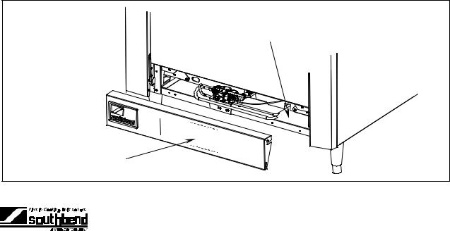
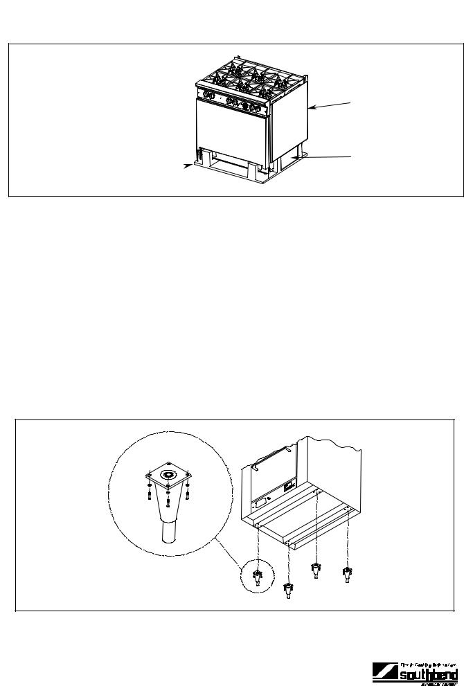
Lighting instructions and the serial plate are located on the interior side of the kick panel, as shown below.
Serial Plate
Lighting Instructions
(inside panel)
OPERATOR’S MANUAL 1182299 REV 1 |
PAGE 3 |
<![endif]>SPECIFICATIONS
SPECIFICATIONS |
MODEL 400 RESTAURANT RANGES |
SPECIFICATIONS
NOTICE
Local codes regarding installation vary greatly from one area to another. The National Fire Protection Association, Inc. states in its NFPA 96 latest edition that local codes are the “authority having jurisdiction” when it comes to installation requirements for equipment. Therefore, installations should comply with all local codes.
Southbend reserves the right to change specifications and product design without notice. Such revisions do not entitle the buyer to corresponding changes, additions, or replacements for previously purchased equipment.
This product is intended for commercial use only, not for household use.
The installation must conform with local codes, or in the absence of local codes, with the National Fuel Gas Code, ANSI Z223.1, Natural Gas Installation Code, CAN/CGA-B149.1, or the Propane Installation Code CAN/CGA-B149.2, as applicable, including:
1.The appliance and its individual shutoff valve must be disconnected from the gas supply piping system during any pressure testing of that system at test pressures in excess of 1/2 psi (3.45 kPa).
2.The appliance must be isolated from the gas supply piping system by closing its individual manual shutoff valve during any pressure testing of the gas supply piping system at test pressures equal to or less than 1/2 psi (3.45 kPa).
MINIMUM CLEARANCES FROM COMBUSTIBLE CONSTRUCTION
! WARNING
There must be adequate clearance between units and combustible construction. Clearance must also be provided for servicing and for operation.
Minimum Clearances for Ranges Built Before April 9, 2001 (25,900 BTU Open Top Burners):
|
Standard Oven |
Convection Oven |
Double Oven Base |
Sides |
6" |
8" |
8" |
Back |
6" |
8" |
6" |
Floor |
0" |
0" |
0" |
Minimum Clearances for Ranges Built After April 8, 2001 (32,000 BTU Open Top Burners):
|
Standard Oven |
Convection Oven |
Double Oven Base |
Sides |
10" |
10" |
10" |
Back |
10" |
10" |
10" |
Floor |
0" |
0" |
0" |
Units are suitable for installation on combustible floors.
Adequate clearance must be provided in the aisle and at the side and rear to allow the door to open sufficiently to permit the removal of the racks and for serviceability.
On units with the convection-type oven, a minimum of 2 inches must be allowed behind the motor and the rear non-combustible enclosure. Care must be taken to provide adequate air circulation to prevent the motor from overheating. No additional clearance from the sides and back is required for service as the units are serviceable from the front.
PAGE 4 |
OPERATOR’S MANUAL 1182299 REV 1 |

MODEL 400 RESTAURANT RANGES |
SPECIFICATIONS |
EXTERIOR DIMENSIONS
Top Views
O |
O |
|
O |
O |
O |
|
R |
R |
R |
|
R |
|
|
|
|
|
|
|
|
|
|
|
|
|
|
|
|
|
|
|
|
|
|
|
|
|
|
|
|
|
|
|
|
|
|
|
|
|
|
|
|
|
|
|
|
|
|
|
|
|
|
|
|
|
|
|
|
|
|
|
|
|
|
|
|
|
|
|
|
|
|
|
|
|
|
|
|
|
|
|
|
|
|
|
|
|
|
|
|
|
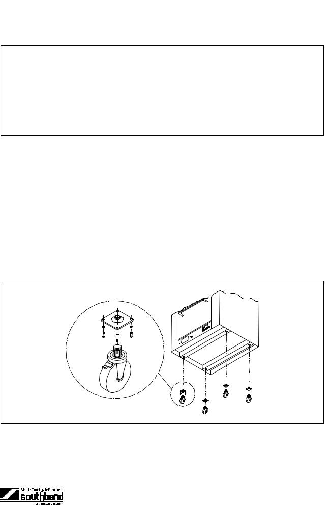
|
|
|
|
|
|
|
|
|
|
|
|
|
|
|
|
|
|
|
|
|
|
|
|
|
|
|
|
|
|
|
|
|
|
|
|
|
|
|
|
|
|
|
|
|
|
|
|
|
|
|
|
|
|
|
|
|
|
|
|
|
|
|
|
|
|
|
|
|
|
|
|
|
|
|
|
|
|
|
|
|
|
|
|
|
|
|
|
|
|
|
|
|
|
|
|
|
|
|
|
|
|
|
|
|
|
|
|
|
|
|
|
|
|
|
|
|
|
|
|
|
|
|
|
|
|
|
|
|
|
|
|
|
|
|
|
|
|
|
|
|
|
|
|
|
|
|
|
|
|
|
|
|
|
|
|
|
|
|
|
|
|
|
|
|
|
|
|
|
|
|
|
|
|
|
|
|
|
|
|
|
|
|
|
|
|
|
|
|
|
|
|
|
|
|
|
|
|
|
|
|
|
|
|
|
|
|
|
|
|
|
|
|
|
424E |
|
|
|
|
|
|
436A |
|
|
|
436A-1GL |
|
|
|
|
|
|
436A-2GL, |
|
|
|
|
|
|
|
436A-2GR |
|
|
|
|||||||||||||||||
|
|
|
|
|
|
|
|
|
|
|
|
|
436D |
|
|
|
436D-1GL |
|
|
|
|
|
|
436A-2TL |
|
|
|
|
|
|
|
436A-2TR |
|
|
|
||||||||||||||
|
|
|
|
|
|
|
|
|
|
|
|
|
|
|
|
|
|
|
|
|
|
|
|
|
|
|
|
|
|
|
436D-2GL |
|
|
|
|
|
|
|
436D-2GR |
|
|
|
|||||||
|
|
|
|
|
|
|
|
|
|
|
|
|
|
|
|
|
|
|
|
|
|
|
|
|
|
|
|
|
|
|
436D-2TL |
|
|
|
|
|
|
|
436D-2TR |
|
|
|
|||||||
|
|
|
|
|
|
|
|
|
|
|
|
|
|
|
|
|
|
|
|
|
|
|
|
|
|
|
|
|
|
|
|
|
|
|
|
|
|
|
|
|
|
|
|||||||
|
|
|
O |
|
|
|
|
|
O |
|
|
|
|
|
|
O |
|
|
|
|
|
|
|
|
O |
|
|
|
|
O |
|
|
|
|
|
|
|
|
|
||||||||||
|
|
|
R |
|
|
|
|
|
|
|
|
|
|
|
|
|
|
|
|
|
|
|
|
|
|
|
|
|
|
|
|
|
|
|
|
R |
|
|
|
|
|
R |
|
|
|
||||
|
|
|
|
|
|
|
|
|
|
|
|
|
|
|
|
|
|
|
|
|
|
|
|
|
|
|
|
|
|
|
|
|
|
|
|
|
|
|
|
|
|
|
|
|
|
|
|
|
|
|
|
|
|
|
|
|
|
|
|
|
|
|
|
|
|
|
|
|
|
|
|
|
|
|
|
|
|
|
|
|
|
|
|
|
|
|
|
|
|
|
|
|
|
|
|
|
|
|
|
|
|
|
|
|
|
|
|
|
|
|
|
|
|
|
|
|
|
|
|
|
|
|
|
|
|
|
|
|
|
|
|
|
|
|
|
|
|
|
|
|
|
|
|
|
|
|
|
|
|
|
|
|
|
|
|
|
|
|
|
|
|
|
|
|
|
|
|
|
|
|
|
|
|
|
|
|
|
|
|
|
|
|
|
|
|
|
|
|
|
|
|
|
|
|
|
|
|
|
|
|
|
|
|
|
|
|
|
|
|
|
|
|
|
|
|
|
|
|
|
|
|
|
|
|
|
|
|
|
|
|
|
|
|
|
|
|
|
|
|
|
|
|
|
|
|
|
|
|
|
|
|
|
|
|
|
|
|
|
|
|
|
|
|
|
|
|
|
|
|
|
|
|
|
|
|
|
|
|
|
|
|
|
|
|
|
|
|
|
|
|
|
|
|
|
|
|
|
|
|
|
|
|
|
|
|
|
|
|
|
|
|
|
|
|
|
|
|
|
|
|
|
|
|
|
|
|
|
|
|
|
|
|
|
|
|
|
|
|
|
|
|
|
|
|
|
|
|
|
|
436A-3G |
448EE |
448EE-2GL |
448EE-2GR |
460AA |
436A-3T |
|
448EE-2TL |
448EE-2TR |
460AD |
436D-3G |
|
|
|
460DD |
436D-3T
|
O |
O |
|
|
O |
|
|
|
O |
O |
|
R |
R |
|
R |
R |
R |
R |
R |
R |
|
R |
R |
|
|
|
|
|
|
|
|
|
|
|
|
|
|
|
|
|
|
|
|
|
|
|
|
|
|
|
|
|
|
|
|
|
|
|
|
|
|
|
|
|
|
|
|
|
|
|
|
|
|
|
|
|
|
|
|
|
|
|
|
|
|
|
|
|
|
|
|
|
|
|
|
|
|
|
|
|
|
|
|
|
|
|
|
|
|
|
|
|
|
|
|
|
|
|
|
|
|
|
|
|
|
|
|
|
|
|
|
|
|
|
|
|
|
|
|
|
|
|
|
|
|
|
|
|
|
|
|
|
|
|
|
|
|
|
|
|
|
|
|
|
|
|
|
|
|
|
|
|
|
|
|
|
|
|
|
|
|
|
|
|
|
|
|
|
|
|
|
|
|
|
|
|
|
|
|
|
|
|
|
|
|
|
|
|
|
460AA-2GL |
|
|
460AA-2GR |
|
|
|
460AA-2RR |
|
|
|
460AA-3GL |
|
|
460AA-3GR |
|
||||||||||||||||||||
|
460AA-2TL |
|
|
460AA-2TR |
|
|
|
460AD-2RR |
|
|
|
460AA-3TL |
|
|
460AA-3TR |
|
||||||||||||||||||||
|
460AD-2GL |
|
|
460AD-2GR |
|
|
|
460DD-2RR |
|
|
|
460AD-3GL |
|
|
460AD-3GR |
|
||||||||||||||||||||
|
460AD-2TL |
|
|
460AD-2TR |
|
|
|
|
|
|
|
|
|
|
|
460AD-3TL |
|
|
460AD-3TR |
|
||||||||||||||||
|
460DD-2GL |
|
|
460AD-2GR |
|
|
|
|
|
|
|
|
|
|
|
460DD-3GL |
|
|
460DD-3GR |
|
||||||||||||||||
|
460DD-2TL |
|
|
460DD-2TR |
|
|
|
|
|
|
|
|
|
|
|
460DD-3TL |
|
|
460DD-3TR |
|
||||||||||||||||
Front Views
A |
A |
A |
A |
|
|
|
I |
I |
I |
I |
I |
|
|
|
|
H |
H |
|
H |
H |
|
|
|
|
|
J |
J |
J |
J |
J |
|
|
|
|
K |
K |
K |
K |
K |
|
|
|
|
|
424E |
436A |
|
448EE |
460AA |
|
436D |
|
|
460AD |
|
|
|
|
460DD |
A
H
460AA-2RR 460AD-2RR 460DD-2RR
Table continues on next page.
<![endif]>SNATIOCIFICESP
OPERATOR’S MANUAL 1182299 REV 1 |
PAGE 5 |
<![endif]>SPECIFICATIONS
SPECIFICATIONS |
MODEL 400 RESTAURANT RANGES |
Table continuing from previous page.
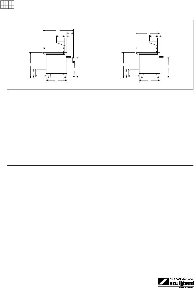
Side Views
B |
|
|
C |
F |
G |
E |
|
L |
P |
|
|
|
Q |
N |
|
M |
|
D |
|
Ranges WITH Convection Oven
B |
|
F |
G |
E |
|
L |
P |
|
|
N |
|
M |
|
D |
|
Ranges WITHOUT Convection Oven
Model |
|
|
|
Exterior Dimensions in Inches and (Millimeters) |
|
|
|
Cook |
Door |
Oven |
|||||
Number |
A |
B |
C |
D |
E |
F |
G |
H |
I |
J |
K |
Top |
Depth |
Bottom |
|
|
width |
depth |
|
|
|
|
|
|
|
|
|
L |
M |
N |
|
424E |
24.25" |
34" |
- |
29.75" |
31" |
12" |
2.75" |
59.5" |
22.5" |
31" |
6" |
37" |
15.5" |
12.5" |
|
(616) |
(864) |
|
(756) |
(787) |
(305) |
(70) |
(1511) |
(572) |
(787) |
(152) |
(940) |
(394) |
(318) |
||
|
|
||||||||||||||
436A |
36.5" |
42" |
8" |
29.75" |
31" |
12" |
2.75" |
59.5" |
22.5" |
31" |
6" |
37" |
15.5" |
12.5" |
|
(928) |
(1067) |
(203) |
(756) |
(787) |
(305) |
(70) |
(1511) |
(572) |
(787) |
(152) |
(940) |
(394) |
(318) |
||
|
|||||||||||||||
436D |
36.5" |
34" |
- |
29.75" |
31" |
12" |
2.75" |
59.5" |
22.5" |
31" |
6" |
37" |
15.5" |
12.5" |
|
(928) |
(864) |
|
(756) |
(787) |
(305) |
(70) |
(1511) |
(572) |
(787) |
(152) |
(940) |
(394) |
(318) |
||
|
|
||||||||||||||
448EE |
48.625" |
34" |
- |
29.75" |
31" |
12" |
2.75" |
59.5" |
22.5" |
31" |
6" |
37" |
15.5" |
12.5" |
|
(1235) |
(864) |
|
(756) |
(787) |
(305) |
(70) |
(1511) |
(572) |
(787) |
(152) |
(940) |
(394) |
(318) |
||
|
|
||||||||||||||
460AA |
60.75" |
42" |
8" |
29.75" |
31" |
12" |
2.75" |
59.5" |
22.5" |
31" |
6" |
37" |
15.5" |
12.5" |
|
(1544) |
(1067) |
(203) |
(756) |
(787) |
(305) |
(70) |
(1511) |
(572) |
(787) |
(152) |
(940) |
(394) |
(318) |
||
|
|||||||||||||||
460AD |
60.75" |
42" |
8" |
29.75" |
31" |
12" |
2.75" |
59.5" |
22.5" |
31" |
6" |
37" |
15.5" |
12.5" |
|
(1544) |
(1067) |
(203) |
(756) |
(787) |
(305) |
(70) |
(1511) |
(572) |
(787) |
(152) |
(940) |
(394) |
(318) |
||
|
|||||||||||||||
460DD |
60.75" |
34" |
- |
29.75" |
31" |
12" |
2.75" |
59.5" |
22.5" |
31" |
6" |
37" |
15.5" |
12.5" |
|
(1544) |
(864) |
|
(756) |
(787) |
(305) |
(70) |
(1511) |
(572) |
(787) |
(152) |
(940) |
(394) |
(318) |
||
|
|
||||||||||||||
Dimension C includes 2" minimum clearance between motor and wall.
Raised-griddle surface on Models 460AA-2RR, 460AD-2RR, and 460DD-2RR is 36.5" (927mm) above floor.
PAGE 6 |
OPERATOR’S MANUAL 1182299 REV 1 |

MODEL 400 RESTAURANT RANGES |
|
|
|
|
SPECIFICATIONS |
|
|
|||||||||||||||||
INTERIOR DIMENSIONS AND UTILITY DATA (for Ranges Built Before April 9, 2001) |
||||||||||||||||||||||||
|
|
|
|
|
|
|
|
|
|
|
|
|
|
|
|
|
|
|
|
|||||
|
Model |
|
|
Left (or Only) Oven |
|
Right Oven |
|
Burners (# and BTU* each) |
|
Gas Connection |
Electric Connection |
|
||||||||||||
|
|
|
Interior Dimensions |
Interior Dimensions |
Total |
Location |
Location |
|
||||||||||||||||
|
Number |
|
|
|
|
|
|
|||||||||||||||||
|
|
|
Width |
|
|
Depth |
|
Height |
Width |
Depth |
Height |
Open |
Oven |
Griddle |
BTU* |
O |
P |
Q |
R |
|
||||
|
|
|
|
|
|
|
|
|||||||||||||||||
|
424E |
19.5" |
|
26.5" |
|
14" |
- |
- |
- |
4 @ |
1 @ |
0 |
135,600 |
2.5" |
30.25" |
- |
- |
|
||||||
|
|
|
(660) |
|
(673) |
|
(356) |
|
|
|
25,900 |
32,000 |
|
|
(64) |
(768) |
|
|
|
|||||
|
436A |
26.125" |
|
24" |
|
14.25" |
- |
- |
- |
6 @ |
1 @ |
0 |
187,400 |
2.5" |
30.25" |
24" |
6" |
|
||||||
|
|
|
(664) |
|
(610) |
|
(362) |
|
|
|
25,900 |
32,000 |
|
|
(64) |
(768) |
(610) |
(152) |
|
|||||
|
436A-1GL |
26.125" |
|
24" |
|
14.25" |
- |
- |
- |
4 @ |
1 @ |
1 @ |
151,600 |
2.5" |
30.25" |
24" |
6" |
|
||||||
|
436A-1TL |
(664) |
|
(610) |
|
(362) |
|
|
|
25,900 |
32,000 |
16,000 |
|
(64) |
(768) |
(610) |
(152) |
|
||||||
|
436A-2GL |
26.125" |
|
24" |
|
14.25" |
- |
- |
- |
2 @ |
1 @ |
3 @ |
131,800 |
2.5" |
30.25" |
24" |
6" |
|
||||||
|
436A-2GR |
(664) |
|
(610) |
|
(362) |
|
|
|
25,900 |
32,000 |
16,000 |
|
(64) |
(768) |
(610) |
(152) |
|
||||||
|
436A-2TL |
|
|
|
|
|
|
|
|
|
|
|
|
|
|
|
|
|
|
|
|
|
|
|
|
436A-2TR |
|
|
|
|
|
|
|
|
|
|
|
|
|
|
|
|
|
|
|
|
|
|
|
|
436A-3G |
26.125" |
|
24" |
|
14.25" |
- |
- |
- |
0 |
1 @ |
4 @ |
96,000 |
6" |
30.25" |
24" |
6" |
|
||||||
|
436A-3T |
(664) |
|
(610) |
|
(362) |
|
|
|
|
32,000 |
16,000 |
|
(152) |
(768) |
(610) |
(152) |
|
||||||
|
436D |
26" |
|
|
26.5" |
|
14" |
- |
- |
- |
6 @ |
1 @ |
0 |
187,400 |
2.5" |
30.25" |
- |
- |
|
|||||
|
|
|
(660) |
|
(673) |
|
(356) |
|
|
|
25,900 |
32,000 |
|
|
(64) |
(768) |
|
|
|
|||||
|
436D-1GL |
26" |
|
|
26.5" |
|
14" |
- |
- |
- |
4 @ |
1 @ |
2 @ |
167,600 |
2.5" |
30.25" |
- |
- |
|
|||||
|
436D-1TL |
(660) |
|
(673) |
|
(356) |
|
|
|
25,900 |
32,000 |
16,000 |
|
(64) |
(768) |
|
|
|
||||||
|
436D-2GL |
26" |
|
|
26.5" |
|
14" |
- |
- |
- |
2 @ |
1 @ |
3 @ |
131,800 |
2.5" |
30.25" |
- |
- |
|
|||||
|
436D-2GR |
(660) |
|
(673) |
|
(356) |
|
|
|
25,900 |
32,000 |
16,000 |
|
(64) |
(768) |
|
|
|
||||||
|
436D-2TL |
|
|
|
|
|
|
|
|
|
|
|
|
|
|
|
|
|
|
|
|
|
|
|
|
436D-2TR |
|
|
|
|
|
|
|
|
|
|
|
|
|
|
|
|
|
|
|
|
|
|
|
|
436D-3G |
26" |
|
|
26.5" |
|
14" |
- |
- |
- |
0 |
1 @ |
4 @ |
96,000 |
6" |
30.25" |
- |
- |
|
|||||
|
436D-3T |
(660) |
|
(673) |
|
(356) |
|
|
|
|
32,000 |
16,000 |
|
(152) |
(768) |
|
|
|
||||||
|
448EE |
19.5" |
|
26.5" |
|
14" |
19.5" |
26.5" |
14" |
8 @ |
2 @ |
0 |
271,200 |
2.5" |
30.25" |
- |
- |
|
||||||
|
|
|
(660) |
|
(673) |
|
(356) |
(660) |
(673) |
(356) |
25,900 |
32,000 |
|
|
(64) |
(768) |
|
|
|
|||||
|
448EE -2GL |
19.5" |
|
26.5" |
|
14" |
19.5" |
26.5" |
14" |
4 @ |
2 @ |
3 @ |
215,600 |
2.5" |
30.25" |
- |
- |
|
||||||
|
448EE -2GR |
(660) |
|
(673) |
|
(356) |
(660) |
(673) |
(356) |
25,900 |
32,000 |
16,000 |
|
(64) |
(768) |
|
|
|
||||||
|
448EE -2TL |
|
|
|
|
|
|
|
|
|
|
|
|
|
|
|
|
|
|
|
|
|
|
|
|
448EE -2TR |
|
|
|
|
|
|
|
|
|
|
|
|
|
|
|
|
|
|
|
|
|
|
|
|
460AA |
26.125" |
|
24" |
|
14.25" |
26.125" |
24" |
14.25" |
10 @ |
2 @ |
0 |
323,000 |
2.5" |
30.25" |
24" |
6" |
|
||||||
|
|
|
(664) |
|
(610) |
|
(362) |
(664) |
(610) |
(362) |
25,900 |
32,000 |
|
|
(64) |
(768) |
(610) |
(152) |
|
|||||
|
460AA-2GL |
26.125" |
|
24" |
|
14.25" |
26.125" |
24" |
14.25" |
6 @ |
2 @ |
3 @ |
267,400 |
2.5" |
30.25" |
24" |
6" |
|
||||||
|
460AA-2GR |
(664) |
|
(610) |
|
(362) |
(664) |
(610) |
(362) |
25,900 |
32,000 |
16,000 |
|
(64) |
(768) |
(610) |
(152) |
|
||||||
|
460AA-2TL |
|
|
|
|
|
|
|
|
|
|
|
|
|
|
|
|
|
|
|
|
|
|
|
|
460AA-2TR |
|
|
|
|
|
|
|
|
|
|
|
|
|
|
|
|
|
|
|
|
|
|
|
|
460AA-3GL |
26.125" |
|
24" |
|
14.25" |
26.125" |
24" |
14.25" |
4 @ |
2 @ |
4 @ |
231,600 |
2.5" |
30.25" |
24" |
6" |
|
||||||
|
460AA-3GR |
(664) |
|
(610) |
|
(362) |
(664) |
(610) |
(362) |
25,900 |
32,000 |
16,000 |
|
(64) |
(768) |
(610) |
(152) |
|
||||||
|
460AA-3TL |
|
|
|
|
|
|
|
|
|
|
|
|
|
|
|
|
|
|
|
|
|
|
|
|
460AA-3TR |
|
|
|
|
|
|
|
|
|
|
|
|
|
|
|
|
|
|
|
|
|
|
|
|
460AA-2RR |
26.125" |
|
24" |
|
14.25" |
26.125" |
24" |
14.25" |
6 @ |
2 @ |
2 @ |
252,900 |
2.5" |
30.25" |
24" |
6" |
|
||||||
|
|
|
(664) |
|
(610) |
|
(362) |
(664) |
(610) |
(362) |
25,900 |
32,000 |
12,000; |
|
(64) |
(768) |
(610) |
(152) |
|
|||||
|
|
|
|
|
|
|
|
|
|
|
|
|
|
|
|
|
|
1@9,500 |
|
|
|
|
|
|
|
460AD |
26.125" |
|
24" |
|
14.25" |
26" |
26.5" |
14" |
10 @ |
2 @ |
0 |
323,000 |
2.5" |
30.25" |
24" |
6" |
|
||||||
|
|
|
(664) |
|
(610) |
|
(362) |
(660) |
(673) |
(356) |
25,900 |
32,000 |
|
|
(64) |
(768) |
(610) |
(152) |
|
|||||
|
460AD-2GL |
26.125" |
|
24" |
|
14.25" |
26" |
26.5" |
14" |
6 @ |
2 @ |
3 @ |
267,400 |
2.5" |
30.25" |
24" |
6" |
|
||||||
|
460AD-2GR |
(664) |
|
(610) |
|
(362) |
(660) |
(673) |
(356) |
25,900 |
32,000 |
16,000 |
|
(64) |
(768) |
(610) |
(152) |
|
||||||
|
460AD-2TL |
|
|
|
|
|
|
|
|
|
|
|
|
|
|
|
|
|
|
|
|
|
|
|
|
460AD-2TR |
|
|
|
|
|
|
|
|
|
|
|
|
|
|
|
|
|
|
|
|
|
|
|
|
460AD-3GL |
26.125" |
|
24" |
|
14.25" |
26" |
26.5" |
14" |
4 @ |
2 @ |
4 @ |
231,600 |
2.5" |
30.25" |
24" |
6" |
|
||||||
|
460AD-3GR |
(664) |
|
(610) |
|
(362) |
(660) |
(673) |
(356) |
25,900 |
32,000 |
16,000 |
|
(64) |
(768) |
(610) |
(152) |
|
||||||
|
460AD-3TL |
|
|
|
|
|
|
|
|
|
|
|
|
|
|
|
|
|
|
|
|
|
|
|
|
460AD-3TR |
|
|
|
|
|
|
|
|
|
|
|
|
|
|
|
|
|
|
|
|
|
|
|
|
460AD-2RR |
26.125" |
|
24" |
|
14.25" |
26" |
26.5" |
14" |
6 @ |
2 @ |
2 @ |
252,900 |
2.5" |
30.25" |
24" |
6" |
|
||||||
|
|
|
(664) |
|
(610) |
|
(362) |
(660) |
(673) |
(356) |
25,900 |
32,000 |
12,000; |
|
(64) |
(768) |
(610) |
(152) |
|
|||||
|
|
|
|
|
|
|
|
|
|
|
|
|
|
|
|
|
|
1@9,500 |
|
|
|
|
|
|
|
460DD |
26" |
|
|
26.5" |
|
14" |
26" |
26.5" |
14" |
10 @ |
2 @ |
0 |
323,000 |
2.5" |
30.25" |
24" |
6" |
|
|||||
|
|
|
(660) |
|
(673) |
|
(356) |
(660) |
(673) |
(356) |
25,900 |
32,000 |
|
|
(64) |
(768) |
(610) |
(152) |
|
|||||
|
|
|
|
|
|
|
|
|
|
|
|
|
|
|
|
|
|
|
|
|||||
|
460DD-2GL |
26" |
|
|
26.5" |
|
14" |
26" |
26.5" |
14" |
6 @ |
2 @ |
3 @ |
267,400 |
2.5" |
30.25" |
24" |
6" |
|
|||||
|
460DD-2GR |
(660) |
|
(673) |
|
(356) |
(660) |
(673) |
(356) |
25,900 |
32,000 |
16,000 |
|
(64) |
(768) |
(610) |
(152) |
|
||||||
|
460DD-2TL |
|
|
|
|
|
|
|
|
|
|
|
|
|
|
|
|
|
|
|
|
|
|
|
|
460DD-2TR |
|
|
|
|
|
|
|
|
|
|
|
|
|
|
|
|
|
|
|
|
|
|
|
|
460DD-3GL |
26" |
|
|
26.5" |
|
14" |
26" |
26.5" |
14" |
4 @ |
2 @ |
4 @ |
231,600 |
2.5" |
30.25" |
24" |
6" |
|
|||||
|
460DD-3GR |
(660) |
|
(673) |
|
(356) |
(660) |
(673) |
(356) |
25,900 |
32,000 |
16,000 |
|
(64) |
(768) |
(610) |
(152) |
|
||||||
|
460DD-3TL |
|
|
|
|
|
|
|
|
|
|
|
|
|
|
|
|
|
|
|
|
|
|
|
|
460DD-3TR |
|
|
|
|
|
|
|
|
|
|
|
|
|
|
|
|
|
|
|
|
|
|
|
|
460DD-2RR |
26" |
|
|
26.5" |
|
14" |
26" |
26.5" |
14" |
6 @ |
2 @ |
2 @ |
252,900 |
2.5" |
30.25" |
24" |
6" |
|
|||||
|
|
|
(660) |
|
(673) |
|
(356) |
(660) |
(673) |
(356) |
25,900 |
32,000 |
12,000; |
|
(64) |
(768) |
(610) |
(152) |
|
|||||
|
|
|
|
|
|
|
|
|
|
|
|
|
|
|
|
|
|
1@9,500 |
|
|
|
|
|
|
|
* BTU values are for natural gas. |
|
|
|
|
|
|
|
|
|
|
|
|
|
|
|||||||||
|
|
|
|
|
|
|
|
|
|
|
OPERATOR’S MANUAL 1182299 REV 1 |
|
|
|
|
|
|
PAGE 7 |
||||||
|
|
|
|
|
|
|
|
|
|
|
|
|
|
|
|
|
||||||||
|
|
|
|
|
|
|
|
|
|
|
|
|
|
|
|
|
||||||||
|
|
|
|
|
|
|
|
|
|
|
|
|
|
|
|
|
||||||||
<![endif]>SNATIOCIFICESP

<![endif]>SPECIFICATIONS
|
SPECIFICATIONS |
|
|
|
|
MODEL 400 RESTAURANT RANGES |
||||||||||||||||
INTERIOR DIMENSIONS AND UTILITY DATA (for Ranges Built After April 8, 2001) |
|
|
|
|
|
|||||||||||||||||
|
|
|
|
|
|
|
|
|
|
|
|
|
|
|
|
|
||||||
|
Model |
Left (or Only) Oven |
|
Right Oven |
|
Burners (# and BTU* each) |
|
Gas Connection |
Electric Connection |
|
||||||||||||
|
Interior Dimensions |
Interior Dimensions |
Total |
Location |
|
|
Location |
|
||||||||||||||
|
Number |
|
|
|
|
|
|
|||||||||||||||
|
|
Width |
Depth |
Height |
Width |
Depth |
Height |
Open |
Oven |
Griddle |
BTU* |
O |
P |
|
Q |
|
|
R |
|
|||
|
|
|
|
|
|
|
||||||||||||||||
|
424E |
19.5" |
26.5" |
14" |
- |
- |
- |
4 @ |
1 @ |
0 |
160,000 |
2.5" |
30.25" |
- |
|
|
- |
|
|
|
||
|
|
(660) |
(673) |
(356) |
|
|
|
32,000 |
32,000 |
|
|
(64) |
(768) |
|
|
|
|
|
|
|
|
|
|
436A |
26.125" |
24" |
14.25" |
- |
- |
- |
6 @ |
1 @ |
0 |
224,000 |
2.5" |
30.25" |
24" |
|
6" |
|
|
|
|||
|
|
(664) |
(610) |
(362) |
|
|
|
32,000 |
32,000 |
|
|
(64) |
(768) |
(610) |
|
(152) |
|
|
||||
|
436A-1GL |
26.125" |
24" |
14.25" |
- |
- |
- |
4 @ |
1 @ |
1 @ |
176,000 |
2.5" |
30.25" |
24" |
|
6" |
|
|
|
|||
|
436A-1TL |
(664) |
(610) |
(362) |
|
|
|
32,000 |
32,000 |
16,000 |
|
(64) |
(768) |
(610) |
|
(152) |
|
|
||||
|
436A-2GL |
26.125" |
24" |
14.25" |
- |
- |
- |
2 @ |
1 @ |
3 @ |
144,000 |
2.5" |
30.25" |
24" |
|
6" |
|
|
|
|||
|
436A-2GR |
(664) |
(610) |
(362) |
|
|
|
32,000 |
32,000 |
16,000 |
|
(64) |
(768) |
(610) |
|
(152) |
|
|
||||
|
436A-2TL |
|
|
|
|
|
|
|
|
|
|
|
|
|
|
|
|
|
|
|
|
|
|
436A-2TR |
|
|
|
|
|
|
|
|
|
|
|
|
|
|
|
|
|
|
|
|
|
|
436A-3G |
26.125" |
24" |
14.25" |
- |
- |
- |
0 |
1 @ |
4 @ |
96,000 |
6" |
30.25" |
24" |
|
6" |
|
|
|
|||
|
436A-3T |
(664) |
(610) |
(362) |
|
|
|
|
32,000 |
16,000 |
|
(152) |
(768) |
(610) |
|
(152) |
|
|
||||
|
436D |
26" |
26.5" |
14" |
- |
- |
- |
6 @ |
1 @ |
0 |
224,000 |
2.5" |
30.25" |
- |
|
|
- |
|
|
|
||
|
|
(660) |
(673) |
(356) |
|
|
|
32,000 |
32,000 |
|
|
(64) |
(768) |
|
|
|
|
|
|
|
|
|
|
436D-1GL |
26" |
26.5" |
14" |
- |
- |
- |
4 @ |
1 @ |
2 @ |
192,000 |
2.5" |
30.25" |
- |
|
|
- |
|
|
|
||
|
436D-1TL |
(660) |
(673) |
(356) |
|
|
|
32,000 |
32,000 |
16,000 |
|
(64) |
(768) |
|
|
|
|
|
|
|
|
|
|
436D-2GL |
26" |
26.5" |
14" |
- |
- |
- |
2 @ |
1 @ |
3 @ |
144,000 |
2.5" |
30.25" |
- |
|
|
- |
|
|
|
||
|
436D-2GR |
(660) |
(673) |
(356) |
|
|
|
32,000 |
32,000 |
16,000 |
|
(64) |
(768) |
|
|
|
|
|
|
|
|
|
|
436D-2TL |
|
|
|
|
|
|
|
|
|
|
|
|
|
|
|
|
|
|
|
|
|
|
436D-2TR |
|
|
|
|
|
|
|
|
|
|
|
|
|
|
|
|
|
|
|
|
|
|
436D-3G |
26" |
26.5" |
14" |
- |
- |
- |
0 |
1 @ |
4 @ |
96,000 |
6" |
30.25" |
- |
|
|
- |
|
|
|
||
|
436D-3T |
(660) |
(673) |
(356) |
|
|
|
|
32,000 |
16,000 |
|
(152) |
(768) |
|
|
|
|
|
|
|
|
|
|
448EE |
19.5" |
26.5" |
14" |
19.5" |
26.5" |
14" |
8 @ |
2 @ |
0 |
320,000 |
2.5" |
30.25" |
- |
|
|
- |
|
|
|
||
|
|
(660) |
(673) |
(356) |
(660) |
(673) |
(356) |
32,000 |
32,000 |
|
|
(64) |
(768) |
|
|
|
|
|
|
|
|
|
|
448EE -2GL |
19.5" |
26.5" |
14" |
19.5" |
26.5" |
14" |
4 @ |
2 @ |
3 @ |
240,000 |
2.5" |
30.25" |
- |
|
|
- |
|
|
|
||
|
448EE -2GR |
(660) |
(673) |
(356) |
(660) |
(673) |
(356) |
32,000 |
32,000 |
16,000 |
|
(64) |
(768) |
|
|
|
|
|
|
|
|
|
|
448EE -2TL |
|
|
|
|
|
|
|
|
|
|
|
|
|
|
|
|
|
|
|
|
|
|
448EE -2TR |
|
|
|
|
|
|
|
|
|
|
|
|
|
|
|
|
|
|
|
|
|
|
460AA |
26.125" |
24" |
14.25" |
26.125" |
24" |
14.25" |
10 @ |
2 @ |
0 |
384,000 |
2.5" |
30.25" |
24" |
|
6" |
|
|
|
|||
|
|
(664) |
(610) |
(362) |
(664) |
(610) |
(362) |
32,000 |
32,000 |
|
|
(64) |
(768) |
(610) |
|
(152) |
|
|
||||
|
460AA-2GL |
26.125" |
24" |
14.25" |
26.125" |
24" |
14.25" |
6 @ |
2 @ |
3 @ |
304,000 |
2.5" |
30.25" |
24" |
|
6" |
|
|
|
|||
|
460AA-2GR |
(664) |
(610) |
(362) |
(664) |
(610) |
(362) |
32,000 |
32,000 |
16,000 |
|
(64) |
(768) |
(610) |
|
(152) |
|
|
||||
|
460AA-2TL |
|
|
|
|
|
|
|
|
|
|
|
|
|
|
|
|
|
|
|
|
|
|
460AA-2TR |
|
|
|
|
|
|
|
|
|
|
|
|
|
|
|
|
|
|
|
|
|
|
460AA-3GL |
26.125" |
24" |
14.25" |
26.125" |
24" |
14.25" |
4 @ |
2 @ |
4 @ |
256,000 |
2.5" |
30.25" |
24" |
|
6" |
|
|
|
|||
|
460AA-3GR |
(664) |
(610) |
(362) |
(664) |
(610) |
(362) |
32,000 |
32,000 |
16,000 |
|
(64) |
(768) |
(610) |
|
(152) |
|
|
||||
|
460AA-3TL |
|
|
|
|
|
|
|
|
|
|
|
|
|
|
|
|
|
|
|
|
|
|
460AA-3TR |
|
|
|
|
|
|
|
|
|
|
|
|
|
|
|
|
|
|
|
|
|
|
460AA-2RR |
26.125" |
24" |
14.25" |
26.125" |
24" |
14.25" |
6 @ |
2 @ |
2 @ |
289,500 |
2.5" |
30.25" |
24" |
|
6" |
|
|
|
|||
|
|
(664) |
(610) |
(362) |
(664) |
(610) |
(362) |
32,000 |
32,000 |
12,000; |
|
(64) |
(768) |
(610) |
|
(152) |
|
|
||||
|
|
|
|
|
|
|
|
|
|
1@9,500 |
|
|
|
|
|
|
|
|
|
|
|
|
|
460AD |
26.125" |
24" |
14.25" |
26" |
26.5" |
14" |
10 @ |
2 @ |
0 |
384,000 |
2.5" |
30.25" |
24" |
|
6" |
|
|
|
|||
|
|
(664) |
(610) |
(362) |
(660) |
(673) |
(356) |
32,000 |
32,000 |
|
|
(64) |
(768) |
(610) |
|
(152) |
|
|
||||
|
460AD-2GL |
26.125" |
24" |
14.25" |
26" |
26.5" |
14" |
6 @ |
2 @ |
3 @ |
304,000 |
2.5" |
30.25" |
24" |
|
6" |
|
|
|
|||
|
460AD-2GR |
(664) |
(610) |
(362) |
(660) |
(673) |
(356) |
32,000 |
32,000 |
16,000 |
|
(64) |
(768) |
(610) |
|
(152) |
|
|
||||
|
460AD-2TL |
|
|
|
|
|
|
|
|
|
|
|
|
|
|
|
|
|
|
|
|
|
|
460AD-2TR |
|
|
|
|
|
|
|
|
|
|
|
|
|
|
|
|
|
|
|
|
|
|
460AD-3GL |
26.125" |
24" |
14.25" |
26" |
26.5" |
14" |
4 @ |
2 @ |
4 @ |
256,000 |
2.5" |
30.25" |
24" |
|
6" |
|
|
|
|||
|
460AD-3GR |
(664) |
(610) |
(362) |
(660) |
(673) |
(356) |
32,000 |
32,000 |
16,000 |
|
(64) |
(768) |
(610) |
|
(152) |
|
|
||||
|
460AD-3TL |
|
|
|
|
|
|
|
|
|
|
|
|
|
|
|
|
|
|
|
|
|
|
460AD-3TR |
|
|
|
|
|
|
|
|
|
|
|
|
|
|
|
|
|
|
|
|
|
|
460AD-2RR |
26.125" |
24" |
14.25" |
26" |
26.5" |
14" |
6 @ |
2 @ |
2 @ |
289,500 |
2.5" |
30.25" |
24" |
|
6" |
|
|
|
|||
|
|
(664) |
(610) |
(362) |
(660) |
(673) |
(356) |
32,000 |
32,000 |
12,000; |
|
(64) |
(768) |
(610) |
|
(152) |
|
|
||||
|
|
|
|
|
|
|
|
|
|
1@9,500 |
|
|
|
|
|
|
|
|
|
|
|
|
|
460DD |
26" |
26.5" |
14" |
26" |
26.5" |
14" |
10 @ |
2 @ |
0 |
384,000 |
2.5" |
30.25" |
24" |
|
6" |
|
|
|
|||
|
|
(660) |
(673) |
(356) |
(660) |
(673) |
(356) |
32,000 |
32,000 |
|
|
(64) |
(768) |
(610) |
|
(152) |
|
|
||||
|
|
|
|
|
|
|
|
|
|
|
|
|
|
|
|
|
|
|
|
|||
|
460DD-2GL |
26" |
26.5" |
14" |
26" |
26.5" |
14" |
6 @ |
2 @ |
3 @ |
304,000 |
2.5" |
30.25" |
24" |
|
6" |
|
|
|
|||
|
460DD-2GR |
(660) |
(673) |
(356) |
(660) |
(673) |
(356) |
32,000 |
32,000 |
16,000 |
|
(64) |
(768) |
(610) |
|
(152) |
|
|
||||
|
460DD-2TL |
|
|
|
|
|
|
|
|
|
|
|
|
|
|
|
|
|
|
|
|
|
|
460DD-2TR |
|
|
|
|
|
|
|
|
|
|
|
|
|
|
|
|
|
|
|
|
|
|
460DD-3GL |
26" |
26.5" |
14" |
26" |
26.5" |
14" |
4 @ |
2 @ |
4 @ |
256,000 |
2.5" |
30.25" |
24" |
|
6" |
|
|
|
|||
|
460DD-3GR |
(660) |
(673) |
(356) |
(660) |
(673) |
(356) |
32,000 |
32,000 |
16,000 |
|
(64) |
(768) |
(610) |
|
(152) |
|
|
||||
|
460DD-3TL |
|
|
|
|
|
|
|
|
|
|
|
|
|
|
|
|
|
|
|
|
|
|
460DD-3TR |
|
|
|
|
|
|
|
|
|
|
|
|
|
|
|
|
|
|
|
|
|
|
460DD-2RR |
26" |
26.5" |
14" |
26" |
26.5" |
14" |
6 @ |
2 @ |
2 @ |
289,500 |
2.5" |
30.25" |
24" |
|
6" |
|
|
|
|||
|
|
(660) |
(673) |
(356) |
(660) |
(673) |
(356) |
32,000 |
32,000 |
12,000; |
|
(64) |
(768) |
(610) |
|
(152) |
|
|
||||
|
|
|
|
|
|
|
|
|
|
1@9,500 |
|
|
|
|
|
|
|
|
|
|
|
|
|
* BTU values are for natural gas. |
|
|
|
|
|
|
|
|
|
|
|
|
|
|
|
|
|
|
|
||
PAGE 8 |
|
|
|
|
|
|
OPERATOR’S MANUAL 1182299 REV 1 |
|
|
|
|
|
|
|
|
|
|
|||||
|
|
|
|
|
|
|
|
|
|
|
|
|
|
|
|
|||||||
|
|
|
|
|
|
|
|
|
|
|
|
|
|
|
|
|||||||
|
|
|
|
|
|
|
|
|
|
|
|
|
|
|
|
|||||||
MODEL 400 RESTAURANT RANGES |
SPECIFICATIONS |
VENTILATION
! WARNING
Improper ventilation can result in personal injury or death. Ventilation which fails to properly remove flue products can cause headaches, drowsiness, nausea, or could result in death.
All units must be installed in such a manner that the flow of combustion and ventilation air are not obstructed. Provisions for adequate air supply must be provided. Do not obstruct the front of the unit at the top by the control panel, or the bottom just below the oven compartment, as combustion air enters through these areas.
NOTICE
Proper ventilation is the owner’s responsibility. Any problem due to improper ventilation will not be covered by the warranty.
All units must be installed in such a manner that the flow of combustion and ventilation air are not obstructed. Provisions for an adequate air supply must be provided. Do not obstruct the front or rear of the unit, as combustion air enters through this area. Be sure to inspect and clean the ventilation system according to the ventilation equipment manufacturer’s instructions.
Ranges with solid tops, such as griddles or hot tops, must always have venting for their flue products at the rear of their burner compartments provided by the hollow area inside a shelf 21" high or a backsplash 17" high. Lack of sufficient venting for the burners in these compartments will cause poor burner and pilot operating characteristics, resulting in inefficient performance. Such conditions also cause high ambient temperatures at the manifold area and create valve and thermostat problems.
Canopies are set over ranges, ovens, etc., for ventilation purposes. It is recommended that a canopy extend 6" past the appliance and the bottom edge be located 6'6" from the floor. Filters should be installed at an angle of 45° or more from the horizontal. This position prevents dripping grease and facilitates collecting the run-off grease in a drip pan, unusually installed with a filter. A strong exhaust fan tends to create a vacuum in the room and may interfere with burner performance or may extinguish pilot flames. Fresh air openings approximately equal to the fan area will relieve such a vacuum.
The exhaust fan should be installed at least 2" above the vent opening at the top of the unit.
If the unit is connected directly to an outside flue, a CSA design certified down draft diverter must be installed at the flue outlet of the oven and connected to the flue.
In case of unsatisfactory performance on any appliance, check the appliance with the exhaust fan in the “OFF” position. Do this only long enough to check equipment performance. Then turn hood back on and let it run to remove any exhaust that may have accumulated during the test.
GAS SUPPLY
The serial plate is located in the compartment below the oven on the right side (left oven on double units). It indicates the type of gas the unit is equipped to burn. All Southbend equipment is adjusted at the factory. Check type of gas on serial plate.
These models are design-certified for operation on natural or propane gases. The unit is shipped configured for the type of gas specified by the purchaser. A kit for conversion to a different type of gas may be purchased from Southbend (see page 32 for conversion instructions).
If applicable, the vent line from the gas appliance pressure regulator shall be installed to the outdoors in accordance with local codes, or in the absence of local codes, with the National Fuel Gas Code, ANSI Z223.1, Natural Gas Installation Code, CAN/CGA-B149.1, or the Propane Installation Code CAN/CGAB149.2, as applicable.
OPERATOR’S MANUAL 1182299 REV 1 PAGE 9
<![endif]>SNATIOCIFICESP

<![endif]>SPECIFICATIONS
SPECIFICATIONS |
MODEL 400 RESTAURANT RANGES |
This appliance should be connected ONLY to the type of gas for which it is equipped.
An adequate gas supply is imperative. Undersized or low pressure lines will restrict the volume of gas required for satisfactory performance. Fluctuations of more than 25% on natural gas or 10% on propane gas will create problems and affect burner operating characteristics. A 1/8" pressure tap is located on the manifold to measure the manifold pressure.
An adequate gas supply line to the unit should be no smaller than the inside diameter of the pipe from the unit to which it is connected.
Purge the supply line to clean out dust, dirt, or other foreign matter before connecting the line to the unit.
All pipe joints and connections must be tested thoroughly for gas leaks. Use only soapy water for testing on all gases. NEVER use an open flame to check for gas leaks. All connections must be checked for leaks after the unit has been put into operation. Test pressure should not exceed 14" W.C.
ELECTRICITY SUPPLY
Units with a convection oven require connection to a supply of electricity. The appliance, when installed, must be electrically grounded in accordance with local codes, or in the absence of local codes, with the
National Electrical Code, ANSI/NFPA 70, or the Canadian Electrical Code, CSA C22.2, as applicable. An electrical diagram is located on the rear of the range, near the motor.
Usually the range is furnished with one or two power cords (one for each oven), each with a standard 115V 60Hz single-phase prong plug. Total maximum amps for 115V units is 12.5.
The range can be ordered to operate on 208V 60Hz 1-phase or 3-phase current, in which case the electric power supply must be wired to one or two junction boxes (one for each oven), each with a terminal block on the rear of the range. Total maximum amps for 208V units is 8.1.
PAGE 10 |
OPERATOR’S MANUAL 1182299 REV 1 |
MODEL 400 RESTAURANT RANGES |
INSTALLATION |
INSTALLATION
NOTICE
These installation procedures must be followed by qualified personnel or warranty will be void.
Local codes regarding installation vary greatly from one area to another. The National Fire Protection Association, Inc. states in its NFPA 96 latest edition that local codes are the “authority having jurisdiction” when it comes to installation requirements for equipment. Therefore, installations should comply with all local codes.
The installation must conform with local codes, or in the absence of local codes, with the National Fuel Gas Code, ANSI Z223.1, Natural Gas Installation Code, CAN/CGA-B149.1, or the Propane Installation Code CAN/CGA-B149.2, as applicable, including:
1.The appliance and its individual shutoff valve must be disconnected from the gas supply piping system during any pressure testing of that system at test pressures in excess of 1/2 psi (3.45 kPa).
2.The appliance must be isolated from the gas supply piping system by closing its individual manual shutoff valve during any pressure testing of the gas supply piping system at test pressures equal to or less than 1/2 psi (3.45 kPa).
Step 1: Unpacking
IMMEDIATELY INSPECT FOR SHIPPING DAMAGE
All containers should be examined for damage before and during unloading. The freight carrier has assumed responsibility for its safe transit and delivery. If damaged equipment is received, either apparent or concealed, a claim must be made with the delivering carrier.
Apparent damage or loss must be noted on the freight bill at the time of delivery. The freight bill must then be signed by the carrier representative (Driver). If the bill is not signed, the carrier may refuse the claim. The carrier can supply the necessary forms.
A request for inspection must be made to the carrier within 15 days if there is concealed damage or loss that is not apparent until after the equipment is uncrated. The carrier should arrange an inspection. Be certain to hold all contents plus all packing material.
1.Cut banding straps and remove corrugated box from range.
2.Cut banding strap holding range to wooden skid.
3.Lift the flue riser off the front of the skid and set it aside.
4.Pull the shelf assembly out from under the base and set it aside.
<![endif]>NOIALLAT INST
OPERATOR’S MANUAL 1182299 REV 1 |
PAGE 11 |
<![endif]>INST ALLATION
INSTALLATION |
MODEL 400 RESTAURANT RANGES |
Base
Flue Riser 
Shelf
Skid 
Step 2a: Install the Legs
A set of four legs is packed with units ordered with legs. (For units ordered with casters, go to Step 2b.)
A threaded leg pad is fastened to the base frame at each corner. Each leg has a corresponding mating thread. The legs can be adjusted to overcome a slightly uneven floor.
1.Raise unit sufficiently to allow leg pads and legs to be attached. For safety, “shore up” and support the unit with an adequate blocking arrangement strong enough to support the load.
2.Attach the four leg pads to the bottom of the range using the lock washers and machine screws. The mounting holes are pre-drilled and threaded.
3.Screw the legs into the holes in the centers of the leg pads.
4.Lower unit gently onto a level surface. Never drop or allow the unit to fall.
5.Use a level to make sure that the range surface is level. The legs can be screwed in or out to lower or raise each corner of the range.
6.Go on to Installation Step 3.
PAGE 12 |
OPERATOR’S MANUAL 1182299 REV 1 |
MODEL 400 RESTAURANT RANGES |
INSTALLATION |
Step 2b: Install Casters and Restraint
NOTICE
For an appliance equipped with casters, (1) the installation shall be made with a connector that complies with the Standard for Connectors for Movable Gas Appliances, ANSI Z21.69 or Connectors for Moveable Gas Appliances, CAN/CGA-6.16, and a quick-disconnect device that complies with the
Standard for Quick-Disconnect Devices for Use With Gas Fuel, ANSI Z21.41, or Quick Disconnect Devices for Use with Gas Fuel, CAN1-6.9, (2) adequate means must be provided to limit the movement of the appliance without depending on the connector and the quick-disconnect device or its associated piping to limit the appliance movement and (3) the restraining means should be attached to a frame member on the back of the unit.
A set of four casters is packed with units ordered with casters (instead of legs).
A threaded leg pad is fastened to the base frame at each corner. Each caster has a corresponding mating thread. The casters can be adjusted to overcome a slightly uneven floor. Casters are provided with a Zerk fitting for proper lubrication when required.
1.Raise unit sufficiently to allow leg pads and casters to be attached. For safety, “shore up” and support the unit with an adequate blocking arrangement strong enough to support the load.
2.Attach the four leg pads to the bottom of the range using the lock washers and machine screws. The mounting holes are pre-drilled and threaded.
3.Screw the casters into the holes in the centers of the leg pads. Install the casters that have a locking brake under the front of the unit.
4.Lower unit gently onto a level surface. Never drop or allow the unit to fall.
5.Use a level to make sure that the range surface is level. The casters can be screwed in or out to lower or raise each corner of the range. After the unit has been leveled, tighten the lock nuts.
6.Secure the restraining-device bracket (item “B” in the following illustration) to a wall stud located as close as possible to the appliance connector inlet and outlet connections. Use four #12 screws (items “C”) and plastic anchors (items “A”) if necessary.
7.Install eye-bolt (item “F”) to a frame member on the rear of the equipment. After checking carefully behind the frame member for adequate clearance, drill a 1/4" hole through the frame member.
<![endif]>NOIALLAT INST
OPERATOR’S MANUAL 1182299 REV 1 |
PAGE 13 |

INSTALLATION |
MODEL 400 RESTAURANT RANGES |
8.Thread hex nut (item “G”) and slide the washer (item “H”) onto the eye-bolt. Insert the eye-bolt through the 1/4" drilled hole and secure with a washer (item “H”) and nylon lock nut (item “I”).
9.Using the spring-loaded snap hooks, attach the restraining device to the bracket and the eye-bolt.
10.Using the cable clamp (item “D”), adjust the restraining device extended length to prevent over-bending or kinking of the appliance connector.
<![if ! IE]><![endif]>INST ALLATION
For units not equipped with flame safety devices, be sure all valves are turned off prior to disconnecting. After reconnecting, be sure all valves are turned off and all pilots are lit.
NOTICE
Adequate means must be provided to limit the movement of the appliance without depending on the connector and the quick-disconnect device or its associated piping to limit the appliance movement.
The restraining means should be attached to a frame member on the back of the unit.
PAGE 14 |
OPERATOR’S MANUAL 1182299 REV 1 |

MODEL 400 RESTAURANT RANGES |
INSTALLATION |
Step 3: Attach Flue Riser and Shelf Assemblies
1.Place the flue riser assembly on the range as shown on the appropriate diagram below.
2.Slide the flue riser assembly over the bayonets until it bottoms out, as shown below.
3.Secure ends of flue riser assembly with two (2) 1/4-20 x 3/4 hex head bolts, flat washers and lockwashers
4.Attach the shelf assembly to the flue riser assembly.
Single-Oven Models
Dual-Oven Models
<![endif]>NOIALLAT INST
OPERATOR’S MANUAL 1182299 REV 1 |
PAGE 15 |

<![endif]>INST ALLATION
INSTALLATION |
MODEL 400 RESTAURANT RANGES |
Step 4: Connect Electricity (for Models with Convection Ovens)
Wiring diagrams are located on the rear of the range. Be sure that the input voltage and phase match the requirements shown on the serial plate.
Ranges ordered with a 115V, 60Hz, single-phase electrical rating are factory-supplied with one or two threewire cords (one for each oven), each with a three-prong plug that fits any standard three-prong grounded receptacle. Single-oven units require a 15 ampere supply, while double-oven units require a 20 ampere supply.
Ranges ordered with a 208/236V, 60Hz, singleor three-phase electrical rating are factory-equipped with one or two two-pole terminal blocks (one for each oven), located behind cover plate(s) located on the rear of the unit. To connect the supply wires, remove the appropriate cover plate. Route the supply wires and the grounding wire through the strain relief fitting to the terminal block. Insert the supply wires, one each, into the two poles of the terminal block and tighten the screws. Insert the ground wire into the grounding lug and tighten the screw. Re-attach the cover plate.
Three phase units are wired as above, using only two supply wires. The third wire is not used and must be properly terminated.
All units are shipped wired as specified by factory order. Conversion between single-phase and three-phase can be accomplished by referring to phase loading and line amperes chart on wiring diagram for wire size and ampere requirements.
Step 5: Connect Gas Supply
If this equipment is being installed at over 2,000 feet altitude and that information was not specified when ordered, contact the appropriate authorized Southbend Service Representative or the Southbend Service Department. Failure to install with proper orifice sizing will result in poor performance and may void the warranty.
The Serial Plate is located in the compartment below the oven on the right side (on double units - left oven). It indicates the type of gas the unit is equipped to burn. All Southbend equipment is adjusted at the factory. Check type of gas on serial plate.
These models are design-certified for operation on natural or propane gases. The unit is shipped configured for the type of gas specified by the purchaser. A kit for conversion to a different type of gas may be purchased from Southbend (see page 32 for conversion instructions).
This appliance should be connected ONLY to the type of gas for which it is equipped.
An adequate gas supply is imperative. Undersized or low pressure lines will restrict the volume of gas required for satisfactory performance. Fluctuations of more than 25% on natural gas or 10% on propane gas will create problems and affect burner operating characteristics. A 1/8" pressure tap is located on the manifold to measure the manifold pressure.
An adequate gas supply line to the unit should be no smaller than the I.D. of the pipe from the unit to which it is connected.
Purge the supply line to clean out dust, dirt, or other foreign matter before connecting the line to the unit.
!CAUTION
ALL PIPE JOINTS AND CONNECTIONS MUST BE TESTED THOROUGHLY FOR GAS LEAKS. USE ONLY SOAPY WATER FOR TESTING ON ALL GASES. NEVER USE AN OPEN FLAME TO CHECK FOR GAS LEAKS. ALL CONNECTIONS MUST BE CHECKED FOR LEAKS AFTER THE UNIT HAS BEEN PUT INTO OPERATION. TEST PRESSURE SHOULD NOT EXCEED 14" W.C.
PAGE 16 |
OPERATOR’S MANUAL 1182299 REV 1 |

MODEL 400 RESTAURANT RANGES |
INSTALLATION |
Step 6: Check the Installation
1.Check that all screws and bolts are tightened.
2.Move the range into the position at which it will be operated.
3.Check that the range is level. If not, adjust the legs.
4.Check that the appropriate clearances are satisfied (see page 4).
Step 7: Adjust Air Shutters and Pilot Heights
All units are adjusted at the factory. However, burner air shutters and pilot heights should be checked at installation and adjusted if necessary. On new installations, start with the top burner of the unit(s) furthest from the gas input to the manifold. This will purge the system of air. Turn main gas supply “ON”.
Step 8: Condition Griddle Surfaces
New griddles should be carefully tempered and cared for in order to avoid possible damage. To break in a new griddle, first wipe it clean. Next, light all the griddle burners and turn them to low for one hour. Then gradually bring each griddle up to frying temperature. Next, spread three or four ounces of beef suet, or as a substitute, baking soda, to season it. Never allow water on a hot griddle and never wash it with soap and water.
<![endif]>NOIALLAT INST
OPERATOR’S MANUAL 1182299 REV 1 |
PAGE 17 |
OPERATION |
MODEL 400 RESTAURANT RANGES |
<![endif]>OPERATION
OPERATION
! DANGER
EXPLOSION HAZARD
In the event a gas odor is detected, shut down equipment at the main shut off valve. Immediately call the emergency phone number of your gas supplier.
!CAUTION
To eliminate gas build up which could result in an explosion, in the event of main burner ignition failure a five minute purge period must be observed prior to re-establishing ignition source.
!CAUTION
Top section pilots, when out, do not interrupt the flow of gas to the burners. Consequently, it is the responsibility of the operator to check the ignition of the burners, immediately after burner value has been turned “ON”. Should ignition fail after 10 seconds, turn off burners, wait 5 minutes, and then try again.
LIGHTING AFTER GAS HAS BEEN SHUT OFF
When turning the main gas supply on after the gas supply has been shut off, do the following:
1.Make sure all of the control valves are in the “OFF” position.
2.Turn on the gas supply.
3.Light the pilots as described below.
4.Light oven first and then wait six minutes before lighting top section. This allows all air to be purged from the range.
OPEN-TOP BURNER SECTIONS
Each open-top burner is controlled by a knob on the front control panel.
To light the pilots of an open-top burner section, do the following:
1.Turn all gas valves to the “OFF” position.
2.Check to make sure pilots are in the correct position.
3.Light the pilots.
4.Adjust the pilot flame as necessary.
PAGE 18 |
OPERATOR’S MANUAL 1182299 REV 1 |

MODEL 400 RESTAURANT RANGES |
OPERATION |
HOT TOP SECTIONS
Range can be ordered with a hot-top section replacing one or more open-top burner sections. Each hot-top is controlled by a knob on the front control panel.
To light the pilots of a hot-top section, do the following:
1.Raise or remove hot-top plate. Every two burners have one pilot located at the front and in between burners.
2.Light the pilot.
3.Pilot flame should be steady blue, large enough to effect ignition.
3. Turn burner valve completely on. The sharp blue flame should be approximately 1/4" to 3/8" high.
5. Replace hot top plate.
NON-THERMOSTATIC GRIDDLE SECTIONS
Ranges can be ordered with thermostatic or non-thermostatic griddle sections. Each griddle is controlled by a knob on the front control panel.
At the end of each use, allow griddle to cool normally. After griddle has cooled, coat griddle surface with a light film of cooking oil to protect surface from moisture.
To light the pilots of a non-thermostatic griddle section, do the following:
1.Raise griddle at front so it is approximately 8" high and block it with two (2) two-by-fours.
2.Ignite pilot tube located under all burners with port at each side of burners. Pilots are supplied and adjusted by a common valve located below the filter on the manifold.
3.Burners should have 1/2" to 5/8" steady blue flame. Adjust if necessary.
4.Lower griddle into position and observe burner operating characteristics through holes in valve panel.
THERMOSTATIC GRIDDLES
Ranges can be ordered with thermostatic or non-thermostatic griddle sections. Each griddle is controlled by a knob on the front control panel.
At the end of each use, allow griddle to cool normally. After griddle has cooled, coat griddle surface with a light film of cooking oil to protect surface from moisture.
To light the pilots of a thermostatic griddle section, do the following:
1.Raise griddle at front so it is approximately 8" high and block it with two (2) two-by-fours.
2.The sensing bulbs must be fully inserted into their tubular holders, which are welded to the underside of the griddle.
3.One pilot tube is located under all burners with ports at each side of the burners. Pilots are supplied and adjusted by a common valve on the manifold. Ignite pilots.
4.Set thermostat dials to maximum, one at a time.
5.Burners should have 1/2" to 5/8" steady blue flame. Adjust if necessary.
6.Lower griddle carefully into position taking extreme care that capillary tubes are coiled under manifold in valve panel compartment. NEVER leave any part of the capillary tube in the burner compartment.
7.Observe burner flame through holes in valve panel, turn thermostat dial at maximum for ten minutes, then turn dial to “LOW” and adjust bypass on thermostat so there is a 1/8" minimum and 1/4" maximum flame at each port.
<![endif]>NATIOEROP
OPERATOR’S MANUAL 1182299 REV 1 |
PAGE 19 |

<![endif]>OPERATION
OPERATION |
MODEL 400 RESTAURANT RANGES |
RAISED-GRIDDLE BROILER SECTION
Ranges can be ordered with a raised-griddle broiler section. Each raised-griddle broiler is controlled by a knob on the front control panel.
At the end of each use, allow griddle to cool normally. After griddle has cooled, coat griddle surface with a light film of cooking oil to protect surface from moisture.
To light the pilots of a raised-griddle broiler, do the following:
1.Remove griddle from unit.
2.Position ceramics on burners with projections pointing downward.
3.Light pilot tube ports (2 at each burner). Adjust pilot flame to be large enough to effect ignition.
4.Place griddle in position on range.
5.Turn valves completely on.
6.Burner should have 1/2" to 5/8" steady blue flame. Adjust if necessary.
SHUTDOWN OF ENTIRE RANGE
To place the range in a standby state (ready for use), do the following:
1.Turn all manual gas valves “OFF.”
2.Turn all thermostats to their lowest position.
To completely shut down the range for an extended period (or prior to disconnecting the gas supply), do the following:
1.Turn all manual gas valves and pilots “OFF.”
2.Turn all thermostats to their lowest position.
3.Turn main supply gas valve “OFF.”
OVENS
Ranges can be ordered with standard or convection ovens. Each oven is controlled by a knob on the front control panel.
To light the pilot of an oven, do the following:
1.Turn oven thermostat to “OFF” position.
2.For convection ovens, turn the fan switch to the “OFF” position.
3.Open door, remove oven bottom and fire plate to expose pilot and burner.
4.Open kick panel and depress red button on oven safety valve.
5.Light constant pilot (the pilot without capillary tube holder).
6.Replace fire plate and oven bottom.
7.Turn thermostat to desired temperature.
PAGE 20 |
OPERATOR’S MANUAL 1182299 REV 1 |
Loading...