

Page 1
®
USBPre 2
Portable High-Resolution Audio Interface
User Guide
Page 2

Legal Notices
Manual Conventions
Product specications and features are subject to
change without prior notication.
Copyright © 2016 Sound Devices, LLC.
All rights reserved.
This product is subject to the terms and conditions
of a software license agreement provided with the
product, and may be used in accordance with the
license agreement.
This document is protected under copyright law. An
authorized licensee of this product may reproduce
this publication for the licensee’s own personal use.
This document may not be reproduced or distributed, in whole or in part, for commercial purposes,
such as selling copies or providing educational services or support.
This document is supplied as a technical guide. Special care has been taken in preparing the information
for publication; however, since product specications
are subject to change, this document might contain
omissions and technical or typographical inaccuracies. Sound Devices, LLC does not accept responsibility for any losses due to the user of this guide.
Trademarks
The “wave” logo and USBPre are registered
trademarks; FileSafe, PowerSafe, SuperSlot,
MixAssist, QuickBoot, and Wave Agent are trademarks of Sound Devices, LLC. Mac and OS X are
trademarks of Apple Inc., registered in the U.S. and
other countries. Windows and Microsoft Excel are
registered trademarks of Microsoft Corporation in
the U.S. and other countries. All other trademarks
herein are the property of their respective owners.
Symbol Description
>
+
i
⚠
This symbol is used to show the order
in which you select menu commands
and sub-options, such as: Main Menu
> Audio indicates you press the Menu
button for the Main Menu, then scroll to
and select Audio by pushing the Control
Knob.
A plus sign is used to show button or
keystroke combinations.
For instance, Ctrl+V means to hold the
Control key down and press the V key
simultaneously. This also applies to
other controls, such as switches and
encoders. For instance, MIC+HP turn
means to slide and hold the MIC/TONE
switch left while turning the Headphone
(HP) encoder. METERS+SELECT means
to hold the METERS button down as you
press the SELECT encoder.
A note provides information and important related recommendations. The
text for notes also appears italicized in
a different color.
A cautionary warning about a specic
action that could cause harm to you,
the device, or cause you to lose data.
Follow the guidelines in this document
or on the unit itself when handling electrical equipment. The text for cautionary notes also appears in a different
color, bold and italicized.
FCC Notice
This device complies with part 15, class B of the FCC
Rules.
www.sounddevices.com
support@sounddevices.com
USBPre 2 User Guide • Rev 1-A • August 8, 2016
This document is distributed by Sound Devices, LLC
in online electronic (PDF) format only. E-published in
the USA.
Sound Devices, LLC
E7556 Road 23 and 33
Reedsburg, Wisconsin USA
Direct: +1 (608) 524-0625
Toll Free: (800) 505-0625
Fax: +1 (608) 524-0655
Page 3
Revision History
This table provides the revision history of this guide.
Rev# Date Firmware
Version
1-A August 2016 v1.03 Initial reformatted & updated, online only publication; replaces
Description
original, old print user guides.
• Updated installation procedure for new v1.20 ASIO driver.
• Updated uninstall procedure for ASIO drivers.
Quick Start Guide section pulled & published in separate
printed QSG document.
• Updated Warranty information in QSG.
• Updated Declaration of Conformity in QSG.
3
Page 4

User Guide
4
Page 5

Table of Contents
USBPre 2 Audio Interface
Front Panel ......................................7
Back Panel ......................................8
Left Panel .......................................9
Right Panel ......................................9
Computer Setup ................................10
System Requirements ..........................10
Setting up Mac OS X ..........................10
Setting up Windows OS ........................12
Installing the ASIO Driver ......................16
Uninstalling the ASIO Driver ....................19
Diagrams and Examples
Setup Examples .................................29
Test and Measurement ........................29
Specifications
Powering ......................................32
Inputs .........................................32
Outputs .......................................33
Updating USBPre 2 Firmware ...................21
DIP Switch Options ..............................22
Inputs .........................................23
Input 2 Loop Source ...........................25
Outputs .......................................25
Adjusting Headphone Monitoring. . . . . . . . . . . . . . . 25
Meters ........................................26
Stand-alone Mode ..............................27
Sample Rate ....................................27
High-Performance Playback ....................30
Block Diagram ..................................31
Recorder .......................................33
Physical ........................................34
5
Page 6

User Guide
6
Page 7
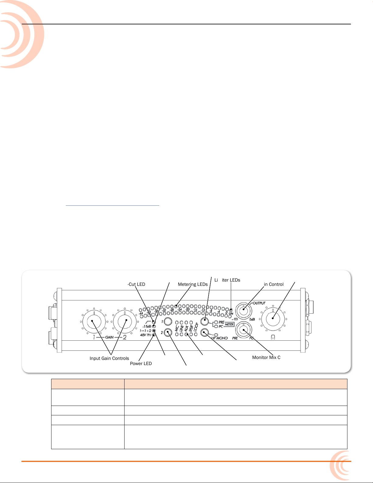
Input Gain Controls
Monitor Mix Control
Phantom Power LED
Output Gain ControlMetering LEDs
Limiter LEDs
Low-Cut LED
15 dB Pad LED Headphone Volume Control
HP Mono Button & LED
Input 1 Split LED
Input Source LEDs
Input Source Button
Meter Source Button
USBPre 2 Audio Interface
The USBPre 2 is a high-resolution,
portable, hardware interface for Macand Windows-based digital audio.
It connects professional microphones,
line-level sources, consumer audio
electronics, and S/PDIF digital sources,
with Mac OS and Windows-based
computers via USB.
With Sound Devices’ renowned preampliers, the USBPre 2 provides the
highest performance in any portable
interface.
i Instructions for quick setup is provided
in the USBPre 2 Quick Start Guide,
shipped with the product and offered
as a free PDF download from the Sound
Devices website.
Front Panel
Topics in this section include:
Front Panel
Back Panel
Left Panel
Right Panel
Computer Setup
System Requirements
Setting up Mac OS X
Setting up Windows OS
Installing the ASIO Driver
Uninstalling the ASIO Driver
Updating USBPre 2 Firmware
DIP Switch Options
Inputs
Outputs
Meters
Stand-alone Mode
Sample Rate
The front panel of the USBPre 2 has the following features:
Feature Description
Input Gain Controls Adjusts input gain. Gain is minimized (not turned off) at full counter-
Phantom Power LED Illuminates when 48 V phantom power is engaged on either mic input.
Input 1 Split LED Illuminates when Input 1 Split is active.
Input Source Button
& Input Source LEDs
clockwise setting. Gain control only affects analog input sources.
Use the buttons to select between the available input types. The LEDs
to the right will illuminate to indicate which source is currently active
for each input.
7
Page 8
User Guide
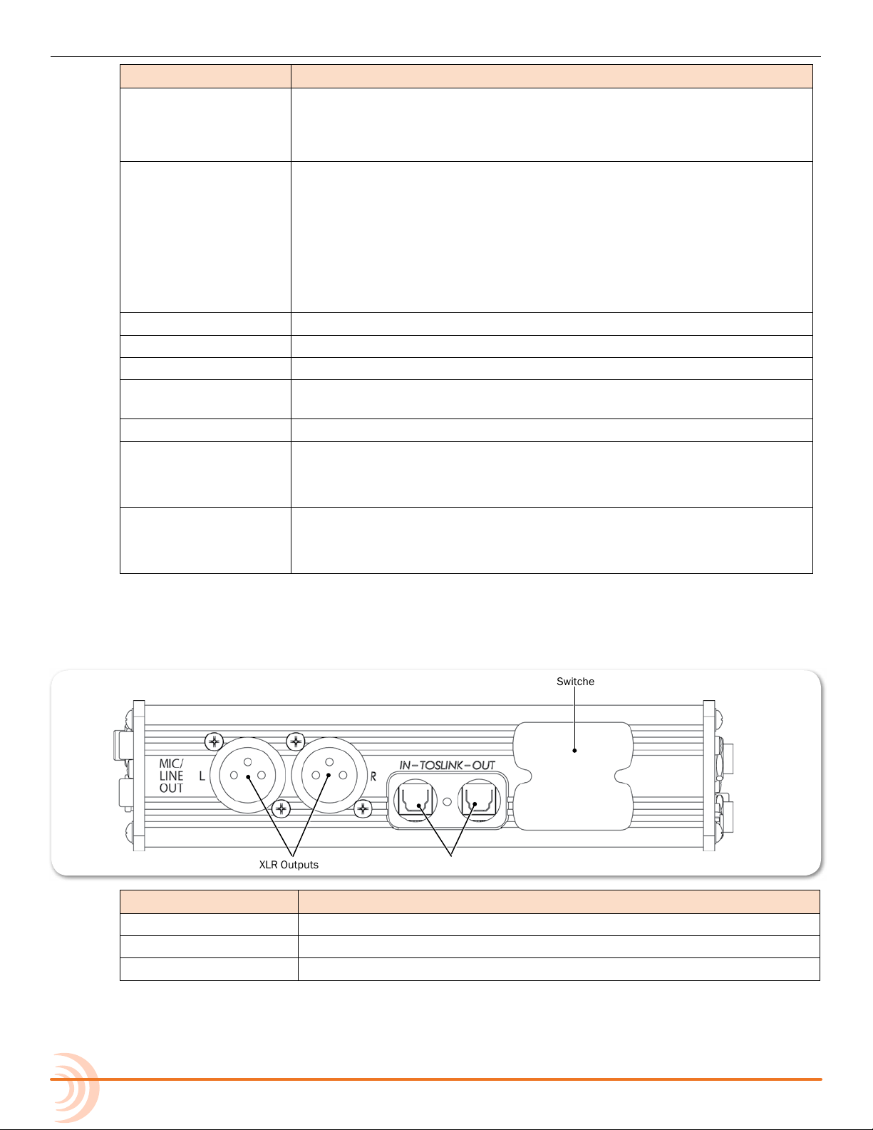
XLR Outputs
DIP Switches
S/PDIF I/O
HP Mono Button &
LED
Monitor Mix Control Selects the signal source to be monitored in the headphones between
Low-Cut LED Illuminates when low-cut lter is engaged on either mic input.
15 dB Pad LED Illuminates when 15 dB pad is engaged on either mic input.
Metering LEDs 23-segment LED meter. Calibrated in dBFS, with peak + VU ballistics.
Meter Source Button
and LEDs
Limiter LEDs Illuminates amber when limiting is occurring.
Output Gain Control Adjusts gain of AUX output and balanced XLR output.
Feature Description
Toggles between mono and stereo monitoring of analog input audio in
headphones. This is especially useful when multi-track recording and
recording from one input. LED illuminates when mono is active. This
function can be congured to affect PC audio as well.
analog source audio (PRE) and computer audio (PC). Listening to PRE
audio allows zero latency monitoring of analog input sources. The
center position mixes monitoring of both source and computer audio.
The signal at the AUX Output and balanced XLR Output is unaffected
by this control.
i S/PDIF digital inputs cannot be monitored in the headphones. S/PDIF
signal can only be monitored after being processed by the computer.
Switches meter source between input or output signal. PRE or PC
Meter LEDs illuminate to indicate current selection.
Headphone Volume
Control
Back Panel
The back panel of the USBPre 2 has the following features:
i May be congured—via a DIP switch setting—to adjust headphone gain
instead of output.
Adjusts headphone gain.
i May be congured—via a DIP switch setting—to adjust XLR and AUX
output levels instead of headphone gain.
Feature Description
XLR Outputs (L/R) Active-balanced XLR analog outputs. Mic/Line switchable.
S/PDIF Input & Output Optical digital (TOSLINK) input and output connectors.
DIP Switches Use DIP switches to congure various aspects of the USBPre 2.
8
Page 9
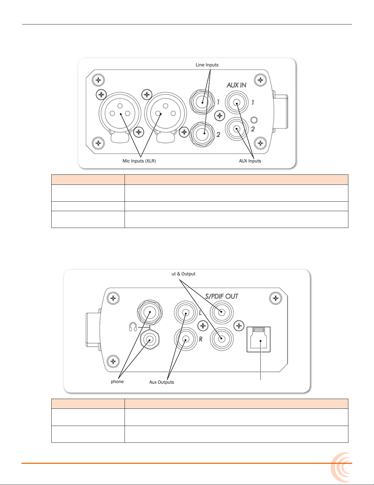
Left Panel
Line Inputs
Mic Inputs (XLR) AUX Inputs (1,2)
Aux Outputs
Headphone
Outputs
S/PDIF Input & Output
USB Port
The left panel of the USBPre 2 has the following features:
Feature Description
Mic Inputs Active-balanced XLR inputs accept low-impedance microphone-level
Line Inputs Accepts balanced line-level signals.
AUX Inputs Accepts consumer-level inputs such as CD players, camcorders, porta-
USBPRE 2 AUDIO INTERFACE
signals.
ble DVD players, and mini-jack from computers via RCA connectors.
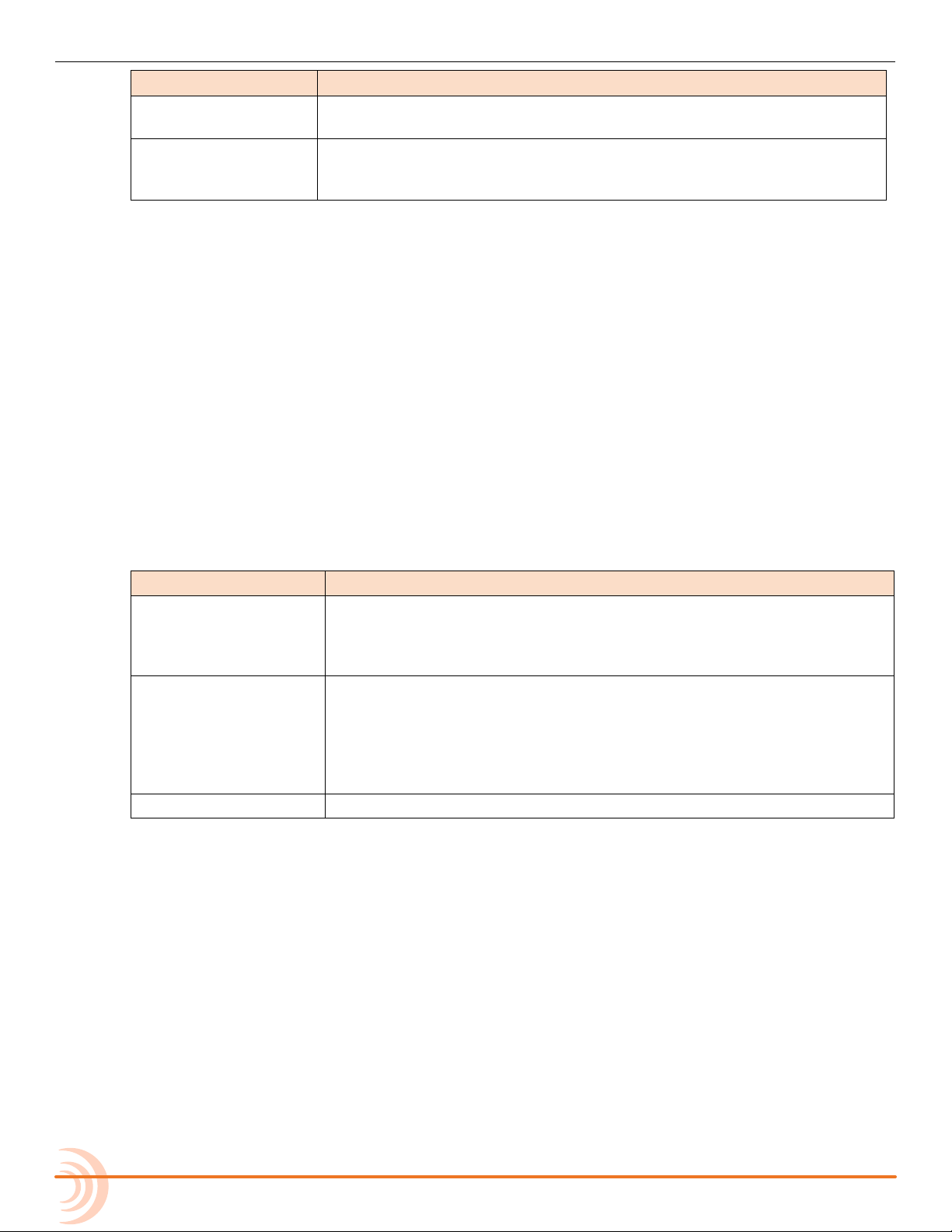
Right Panel
The right panel of the USBPre 2 has the following features:
Feature Description
Headphone Outputs 3.5 mm and ¼-inch TRS stereo headphone outputs can drive low-im-
AUX Outputs Audio output to feed powered loud speakers, CD recorders, camcord-
pedance headphones.
ers, or portable DVD recorders. RCA connectors; computer audio only.
9
Page 10
User Guide
Feature Description
S/PDIF I/O Coaxial digital input and output connectors. Input is selected via the
USB Port Standard USB B-type connector for interconnection with the comput-
Computer Setup
Initial connection and setup procedures for the USBPre 2 are provided in
the product’s Quick Start Guide. The following sections provide system
requirements and rmware update procedures. They also have more
information on adjusting sample rates as well as how to ensure that the
USBPre 2 is recognized as the default recording and playback device on
computers with various operating systems.
System Requirements
The requirements below outline the minimum congurations for systems using
the USBPre 2. Software applications used with the USBPre 2 have their own requirements that may be in addition to the requirements of the USBPre 2. Consult your software’s documentation.
front panel’s Input Source button.
er; provides all data and power to he USBPre 2 via USB bus powering.
USB 1.1 and 2.0 compliant.
Feature Description
Operating Systems • Windows XP (SP3), Windows Vista, Windows 7 (both 32 and 64 bit)
• Macintosh OS 10.4 or later
• Linux Kernel 2.6.0 or later (Requires standard ALSA snd-usb-audio
module)
USB Audio Device
Class
USB Connection • Full USB 1.1 or 2.0 compliance
i For Notebook Computer users: For proper operation of the USBPre 2, turn off all
power management when using the USBPre 2 for audio recording. Power management reduces processor speed, system bus speed, spins down hard disks, shuts
down displays, or a combination of the above to reduce current consumption and
extend battery run time. The change in state from active to power-saving mode
can disrupt data on the USB bus and cause unintended dropouts.
Sound Devices cannot guarantee that a given computer can be used satisfactorily
with the USBPre 2 based exclusively on the fact that it meets the above requirements.
• Windows, Linux and Mac OS versions below 10.5.8 utilize USB Audio Device Class 1.0 drivers that will limit the USBPre 2 to sampling
rates of 48 kHz and lower.
• Mac OS 10.5.8 and greater utilizes USB Audio Device Class 2.0
drivers that will allow the full range of sample rates that the USBPre 2 is capable of.
Setting up Mac OS X
The following procedure and images depict steps for version 10.6 of OS X; steps
for earlier versions will vary.
10
Page 11
USBPRE 2 AUDIO INTERFACE
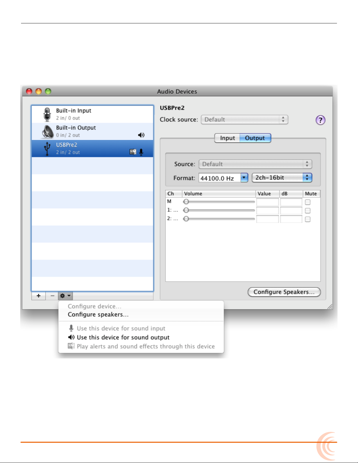
To set audio defaults and sample rate in OS X:
1. Select Applications > Utilities > Audio MIDI Setup. The Audio MIDI Setup
dialog box appears.
2. Click USBPre 2 to highlight it in the list.
3. Click the Gear icon (as shown) and select Use this device for sound output.
4. Click the Gear icon again and select Use this device for sound input.
i For OS X 10.5 and earlier, check the System Settings section to ensure that
USBPre 2 is selected for both the Default Input and Default Output drop-down
menus.
5. With USBPre 2 still highlighted in the Audio MIDI Setup dialog box, click the
Format drop-down menu options to adjust the sample rate and bit depth.
11
Page 12

User Guide
i For OS X 10.5 and earlier, select USBPre 2 from the Properties For drop-down
menu, then in the Audio Input and Audio Output sections, set the sample rate,
channel count, and bit depth.
Setting up Windows OS
This section provides procedures for checking audio defaults and setting sample
rates on various Windows operating systems, including Windows 7, Vista and
XP.
The following procedure and images depict steps for Windows 7 and Vista.
To set audio defaults and sample rate in Windows 7 & Vista:
1. Select Start > Control Panel > Sound. The Sound dialog box appears.
12
Page 13

USBPRE 2 AUDIO INTERFACE
2. Click the Playback tab.
3. Select (single click) the device labeled USBPre 2 in the list.
4. Click Set Default. A green Checkmark icon and the words “Default Device”
will appear in the list, indicating that the USBPre 2 is now the default playback device.
5. Click the Properties button. The Speakers Properties dialog box appears.
6. Click the Advanced tab.
7. In the Default Formate section, select the sample rate and bit depth to use
from the drop-down menu.
8. Click OK. The Speakers Properties dialog box closes.
9. From the Sound dialog box, click the Recording tab and repeat the above
steps 3 and 4.
13
Page 14

User Guide
The following procedure and images depict steps for Windows XP.
To set audio defaults in Windows XP:
1. Select Start > Control Panel. The Control Panel view will either be in “Clas-
2. Click Sounds, Speech, and Audio Devices. Proceed to step 4.
sic view”—skip to step 3—or “Category view”—proceed to step 2.
14
3. Click Sounds and Audio Devices.
Page 15

USBPRE 2 AUDIO INTERFACE
4. In the Sounds and Audio Devices Properties dialog box, click the Audio tab.
15
Page 16

User Guide
5. In the Sound playback section, select USBPre 2.
6. In the Sound recording section, select USBPre 2.
7. Click OK.
Installing the ASIO Driver
As a class-compliant audio device, the USBPre 2 is limited to a maximum data
rate of 24-bit, 48 kHz in Windows, Linux, and Mac OS versions 10.4 to 10.5.7.
Mac OS 10.5.8 and later support the audio class 2.0 device and can address the
USBPre 2 up to 24-bit, 192 kHz. To enable higher sampling rates in Windows
OS, the ASIO driver is needed.
The ASIO driver for the USBPre 2 allows for low-latency operation and sample
rates up to 192 KHz on Windows computers. The ASIO drivers include a WDM
counterpart, so applications that use standard WDM for playback and recording
will still operate as normal after installation. After installation, the USBPre 2 will
be available as an ASIO device in applications that utilize ASIO.
i If a previous version of the USBPre 2 ASIO driver is installed on the Windows-
based computer, it should be uninstalled prior to installing a newer version. The
16
Page 17

USBPRE 2 AUDIO INTERFACE
latest version of driver serves as a driver for both 64-bit and 32-bit systems. For
uninstall instructions, see Uninstalling the ASIO Driver.
To install the ASIO driver:
1. Go to the USBPre 2 Download page on the Sound Devices website at:
www.sounddevices.com/support/downloads/usbpre2-rmware and down-
load the latest USBPre 2 ASIO driver, which is a zipped le.
2. Right-click on the downloaded ZIP le and select Extract All. Then, select a
destination and click Extract.
3. Locate and open the extracted folder.
4. Connect the USBPre 2 using a standard USB A-to-B cable.
5. Double click on the setup.cmd le in the extracted folder to begin the
installation process.
6. Click Run, when prompted, to run the installer program.
7. Follow the on-screen instructions to run the installation.
A. When prompted to select a language, do so and click OK.
17
Page 18

User Guide
B. When offered options to install, uninstall, or exit, click Install the Driver.
C. A dialog with a status bar appears to show progress. Each time a prompt
for conrmation appears, click Install to continue.
18
4. After the installation completes successfully, disconnect, and then reconnect
the USBPre 2 prior to use.
Page 19

USBPRE 2 AUDIO INTERFACE
Uninstalling the ASIO Driver
Before installing a new version of the ASIO driver, any existing version on the
computer must be uninstalled.
To uninstall the ASIO driver:
1. Do one of the following:
X Windows 7 & Vista: Click Start > Control Panel and select Programs and
Features.
X Windows XP: Click Start > Control Panel and select Add/Remove Pro-
grams.
2. Locate the USBPre 2 USB ASIO driver in the list, highlight it, and click
Uninstall.
Step 2 completes the procedure on Windows XP and Vista computers. For
Windows 7 computers, further steps are required.
i The remaining steps in this procedure are for removing ASIO drivers from
computers running Windows 7 only.
3. Restart the computer.
4. Right-click Computer and select Properties.
5. On the left sidebar of the System window, click Device Manager to open the
Device Manager window.
6. Expand the Sound, video, and game controllers section.
19
Page 20

User Guide
7. Right-click the USBPre 2 entry and select Uninstall.
8. When the conrmation dialog appears, ensure that the check box titled “Delete the driver software for this device” is selected, and click OK.
20
9. In the Device Manager window, expand the Universal Serial Bus controllers
section and repeat steps 7 & 8.
Page 21

USBPRE 2 AUDIO INTERFACE
Updating USBPre 2 Firmware
To ensure optimum performance, Sound Devices recommends you update rmware to the latest version as soon as possible.
To install the latest rmware:
1. Download the latest rmware from Sound Devices. New versions of rmware are provided as free downloads from the Sound Devices website at:
http://www.sounddevices.com/support/downloads/usbpre2-rmware.
Ensure that you select the le that corresponds to your operating system.
2. Connect the USBPre 2 to the computer with the supplied USB cable and
make certain it is recognized by the computer as a standard sound card.
3. Do one of the following:
X Macintosh users: Double-click on the downloaded DMG le. A disk la-
beled USBPre2-# (where # represents the version number) appears on
the desktop. Open this disk and run the application bearing the same
name.
X Windows users: If the ASIO driver for the USBPre 2 is installed, it must
be removed in order to successfully update the USBPre 2 rmware. The
ASIO driver can be reinstalled after successfully updating the rmware.
Double-click the downloaded USBPre 2 executable le to run it. Next,
click the Update button to update the rmware, and then, when
directed, disconnect and reconnect the USB cable of the USBPre 2.
21
Page 22

User Guide
DIP Switch Options
The DIP switches on the back panel of the USBPre 2 may be used to control
various features. The settings are divided into two groups: A and B.
To adjust an individual switch:
X Carefully move the switch with a slender tool.
In the following descriptions, “up” refers to the direction opposite the numerical
labels on the switch casings.
a settings switch Description
48 V Phantom Power 9 & 10 Up position engages 48 Volt phantom power on balanced
microphone inputs, which is required for condenser
microphones.
Low-Cut Filter 7 & 8 Up position engages low-cut lter on balanced microphone
inputs: -3 dB at 80 Hz. 12 dB per octave.
Limiter 5 & 6 Up position engages limiters on balanced microphone inputs.
The signal is attenuated above -4 dBFS.
15 dB Pad 3 & 4 Up position reduces gain by 15 dB on balanced microphone
inputs. This is useful for sensitive microphones or very loud
program material.
N/A 2 This switch is not used at present.
Dual Mono 1 Up position disables input 2 and routes input 1 signal to both
tracks.
B settings switch Description
Balanced Output
Level
Headphone Mono 3 Adjusts what signals are summed when Headphone Mono
Meter PRE/PC 4 Adjusts whether or not the meter source switches automat-
1 & 2 Determines level of balanced XLR outputs. Up position sets
level to Line level (0 dBu). Down position sets it to Mic level
(-40 dBu).
mode is active. Up position is for input signals only. Down
position is for input signals and output audio from the
computer.
ically to PC metering when computer audio is present. Up
position sets it to Automatic. Down position sets it to Manual.
22
Page 23

USBPRE 2 AUDIO INTERFACE
Input Source buttons
&
Input Source LEDs
Input Gain
controls
B settings switch Description
HP/Output 5 Determines which controls on the front panel adjusts head-
phone gain and main output gain. The up position is the default, which sets the larger control to adjust headphone gain,
while the smaller one controls the main output gain.
When in down position, the functionality of the controls are
reversed so that the larger one controls main output gain
and the smaller one controls headphone gain.
Headphone Signal to
Outputs
Input Select Lock 7 When in up position, Input Source buttons function normally.
Stand-Alone Sample
Rate
6 When in up position, only computer audio is sent to outputs.
When in down position, main (analog) output source is the
same as headphone signal source and affected by Monitor
Mix control.
i In Stand-alone mode, input signal is always routed to the
outputs, and this setting has no effect.
When in down position, Input Source buttons are disabled,
and the Input Source selection is locked.
8, 9 & 10 Sets the operating sample rate when in Stand-Alone mode
according to the associated diagram. In Soundcard Mode,
sample rate is determined by the computer.
Inputs
The USBPre 2 has two available input channels. The source for each input is
independently selected using the Input Source buttons on the front panel, and
the selected source is indicated by an illuminated LED next to the respective
Input Source button.
i The Input Source buttons may be locked—via a DIP switch setting—to prevent
accidental switching of the input sources.
23
Page 24

User Guide
Microphone • Phantom Power - The USBPre 2 provides 48-volt phantom power
Line The Line Inputs use balanced, quarter-inch connectors and accept +4
Aux The Aux inputs use unbalanced, RCA connectors and accept -10 dBu
inputs Description
for condenser microphones connected to the XLR inputs. Phantom
power can be engaged independently for each input. See DIP Switch
Options. Condenser microphones that can operate on phantom voltages from 11-52 volts will function properly with 48-volt phantom.
i Dynamic microphones typically do not require phantom power. A properly
connected balanced, dynamic microphone is not affected by the presence
of phantom power nor will it draw any current. However, it is good
practice to turn phantom power off when not needed. Poor or incorrectly
wired microphone cable can cause audible artifacts in microphone
signals. Some wireless receivers outputs are adversely affected by the
presence of phantom power; therefore, consult the wireless receiver’s
documentation.
• Low-Cut Filter - This lter attenuates low frequency signals, and is
useful in conditions where low frequency signal is causing overload
before the desired gain is reached, such as windy environments or
hand-held microphones.
• Input Pad - With some combinations of microphone sensitivity and
sound pressure levels, the microphone input of the USBPre 2 can
become overloaded even when the input gain is at its lowest level. A
15 dB pad may be engaged—via a DIP switch setting—on the microphone input to reduce its sensitivity.
• Input Limiters - In environments where high sound pressure levels
may occur unexpectedly, input limiting prevents distortion by attenuating signals that surpass the input threshold level. In normal operation with properly set input levels, the threshold of an input limiter
is rarely reached. Signals below the threshold are not affected by the
limiter. Limiters may be engaged independently on each microphone
input—via a DIP switch setting. The amber LIM LED’s on the right
side of the meters will illuminate to indicate when limiting is occurring.
dBu analog signal (sometimes referred to as “Professional” line level).
Wiring is tip: signal (+), ring: signal (-), and sleeve: ground.
analog signal, which is sometimes referred to as “Consumer” line level.
This input is designed for signal from CD players, camcorders, portable
DVD players, and other similar devices.
24
i Signal output from turntables without built-in phono preampliers is too
weak for the USBPre 2’s auxiliary inputs. A separate phono preamplier
may be required depending on the design of the turntable.
Digital Digital signal in the S/PDIF format can be input to either the coaxial
RCA connector or the optical TOSLINK connector. If signal is present
at both the optical and coaxial input, the signal from the optical input
takes precedence.
i Sample rates below 32 kHz are not supported on the digital connections.
The optical connections do not support the 192 kHz sampling rate.
Page 25

Input 2 Loop Source
Input 2 has an additional source labeled LOOP. This input source does not correspond to any physical connections on the USBPre 2. When LOOP is selected,
input 2’s source is derived from the left channel of the computer audio signal
(post digital-to-analog conversion). The Input 2 Gain control affects signal. The
Output Gain control does not affect the level of the signal going into input 2.
The LOOP source is useful for test and measurement applications where a reference signal is required to be routed back to an input.
Outputs
Output connections are located on the right and back panels of the USBPre 2.
outputs Description
Main Signal level at the balanced XLR outputs and unbalanced AUX outputs is
USBPRE 2 AUDIO INTERFACE
adjusted with the Output Gain control. The signal source for the outputs
is the output audio from the computer. This source may be changed to
the same source as the headphone output, by using the back panel DIP
switches. The balanced XLR outputs are set to line level by default, but
may be set to mic level via a DIP switch setting.
i The Windows Volume (controlled with the “speaker” icon in the sys-
tem tray) and the Mac Volume control affect the level of the computer’s
output audio before it reaches the USBPre 2. It is generally best practice
to set the volume control to 100% and make adjustments to the output
level with the USBPre 2’s Output Gain control.
Digital When the USBPre 2 is used as a computer audio interface, the sample
rate of the digital outputs (coaxial S/PDIF and optical TOSLINK) is
determined by the application settings on the computer. In Stand-alone
mode, the sample rate is determined by the positions of the back panel
DIP switches.
i Optical (TOSLINK) outputs are inoperable at 192 kHz sample rate.
Headphone The USBPre 2 has two headphone output connections and a high
current headphone amplier for monitoring analog input audio,
computer audio, or a mix of both.
⚠ The USBPre 2 is capable of driving headphones to dangerously
high levels. Be aware of headphone level controls at all times.
Adjusting Headphone Monitoring
Use the Headphone Volume control to adjust the level of the signal going to the
headphones.
Use the Monitor Mix Control on the front panel to adjust the mix between direct
audio from the inputs (fully counter-clockwise) and output audio from the
computer (fully clockwise). The signal for input audio is derived from the inputs
before analog-to-digital conversion.
Headphone Mono mode sums the input signals from both inputs into a mono
mix for the headphones.
25
Page 26

User Guide
Monitor Mix Control
Output Gain Control
Headphone Volume Control
HP Mono Button
&
LED
Meter Source button
&
Meter Source LEDs
To toggle Headphone Mono mode:
X Push the HP MONO button on the front panel. The Headphone Mono LED will
illuminate when Headphone Mono mode is active.
i Optionally—via a DIP switch setting—the stereo signal from the computer may also
be summed when Headphone Mono mode is engaged.
Meters
The USBPre 2 features a 23-segment, 2 channel LED meter. The meter displays
both the peak level of source audio and average (VU) levels simultaneously.
Zero (0) dB on the meter is calibrated to 0 dBFS signal coming from the computer.
The current source signal for the meter is indicated by an illuminated LED—PRE
or PC—next the Meter Source button.
To toggle the meter source:
X Push the Meter Source button.
26
When the meter source is set to PC the meter displays the audio level for signal
Page 27

coming from the computer. In this mode, the top row of the meter displays the
left channel level, and the bottom row displays the right channel level.
When the meter source is set to PRE, the meter displays the audio level for
signal at the active inputs. In this mode, the top row of the meter displays the
level for the selected input source on channel one, and the bottom row displays
the level for the selected input source on channel 2.
When signal is output from the computer, the meter source switches from PRE
to PC automatically. However, this behavior can be modied—via a DIP switch
setting—so that the source is switched manually.
Stand-alone Mode
In Stand-Alone mode, the USBPre 2 operates as a microphone preamplier
with both digital and analog outputs. It can also accept digital signals and
output analog audio. The USBPre 2 will automatically enter stand-alone mode
when connected to a USB jack supplying USB power but is not associated with
a running operating system—a powered USB hub that is not attached to a
computer, for instance.
USBPRE 2 AUDIO INTERFACE
i The USBPre 2 can also be forced into Stand-alone mode when connected to a
computer supplying USB power by holding down the Meter Source button when
attaching the USB cable.
In Stand-Alone mode, all front panel controls perform the same functions as
when the USBPre 2 is in Interface mode, except that the Meter Source button is
disabled and the meter source signal is locked to PRE. Since there is no reference clock from the computer, the operating sample rate is set using the back
panel DIP switches.
Sample Rate
In Interface mode, the USBPre 2 operates at the sample rate set from the host
operating system, and the DIP switches related to sample rate are ignored. It is
further possible to change the sampling rate of the USBPre 2 within some applications’ audio preferences.
i In Windows XP there is no global sample setting, and the sample rate must be set
by the application in use.
In Stand-alone mode, the sample clock is generated by the USBPre 2’s internal
sample clock generator, and the Sample rate is set by adjusting the DIP switches on the back panel of the USBPre 2. This affects the internal sample rate of
the USBPre 2 as well as the sample rate output from the digital outputs.
i Sample rates below 32 kHz are not supported on the coaxial or optical (TOSLINK)
digital interconnections. The sampling rate of 192 kHz is not supported on
TOSLINK interconnections.
27
Page 28

User Guide
Locked Sample Rates to External Sources
The sample rate of the USBPre 2 may be locked to the sample rate of an
external S/PDIF signal. When a digital signal is connected to either the coaxial
or optical input, the S/PDIF Input Source LED will illuminate to indicate that the
USBPre 2 is locked to the sample rate of the incoming digital signal. Also, when
the signal is removed or turned off, the S/PDIF Input Source LEDs will ash for
30 seconds.
To make a digital recording with the computer at a locked sample rate, be certain that the incoming digital signal is valid (solid illumination of S/PDIF Input
Source LEDs) and that the software driver is set to the same sample rate as
that of the incoming digital signal.
If the USBPre 2 senses a discrepancy in the incoming digital signal such as a
clocking error, the Meter Source LEDs will ash until the Meter Source button is
pushed.
28
Page 29

Diagrams and Examples
related to USBPre 2 modes—Interface
and Stand-alone—as well as a couple of
setup examples for the audio interface.
Topics in this section include:This section provides a block diagram
Setup Examples
Test and Measurement
High-Performance Playback
Block Diagram
Setup Examples
This section provides examples of two possible setups: one best used for test
and measurement, and another aimed more for high-performance playback.
Test and Measurement
The high quality preampliers and portability of the USBPre 2 make it a perfect
interface for test and measurement applications. A requirement for measuring
a transfer function is the ability to monitor the output reference signal from the
computer. The LOOP source of input 2 enables a copy of the computer audio
left channel to be internally routed to input 2. This allows reference signal to be
sent back into the measurement application without additional cabling.
The USBPre 2 supports native sample rates below 44.1 kHz to provide better
FFT resolution for low-frequency audio measurements
29
Page 30

User Guide
Input 1 set to Mic (XLR)
Input 2 set to Loop
To PA
LEFT
RIGHT
Power amplifier input
Monitors
Power amplifier
High-Performance Playback
The USBPre 2 can provide high-quality audio output from a computer to reference monitors in a studio control room or a home stereo system. Depending on
the connectivity of the monitors, the balanced XLR outputs, unbalanced RCA
outputs, or digital S/PDIF outputs can be used to send computer audio to the
monitors.
30
Page 31

Block Diagram
DIAGRAMS AND EXAMPLES
31
Page 32

Specifications
the USBPre 2.
Topics in this section include:This section provides specications for
Powering
Features and specications are subject
to change without prior written notice.
Visit the Sound Devices website for the
latest product information.
Powering
Name DescriptioN
External Power Supply • USB bus powered.
• 5 V (+/- 10%)
• 500 mA max current from USB port (USBPre 2 will not function if
connected through a passive USB connection or hub)
Phantom Power • 48 V through 6.8k ohm resistors. Each mic input supplies 10 mA
Inputs
Outputs
Recorder
Physical
Inputs
Name DescriptioN
Frequency Response
(reference 1 kHz tone/
192 kHz sample rate)
THD + Noise • 0.05% max (any input to PC recording, gain control at min, input
Equivalent Input Noise
(MIC inputs)
Any input to PC recording:
• 10 Hz - 40 Hz, +/-0.5 dB
• -3 dB at 65 kHz
driven to -6 dBFS)
• 0.009% max (AUX output, 0 dB V output, 100k ohm load)
• 0.05% max (Headphones output, 2 V rms output, 600 ohm load)
• 127 dBu min (22 Hz - 22 kHz bandwidth, 150 ohm source, gain
control fully clockwise, 15 dB pad out)
PC source to AUX or XLR output:
• 10 Hz - 40 Hz, +/-0.5 dB
• -3 dB at 65 kHz
32
Page 33

Input Clipping Level
(1% THD)
Input Sensitivity
(typical, for 0 dBFS)
Input Impedance
(actual)
Input Limiter Threshold • Mic: -4 dBFS
Low Cut • Mic: -3 dB at 80 Hz, 12 dB per octave
S/PDIF Digital • 24 or 16 bit input
Outputs
Output Clipping Level
(1% THD, PC-controlled
output levels at max)
Output Impedance • Headphone (actual): 22 ohms
Low Cut • Mic: -3 dB at 80 Hz, 12 dB per octave
Name DescriptioN
• Mic: -10 dBu (0.25 V rms)
• Mic: (15 dB pad) +4 dBu
(0.78 V rms)
• Mic: -10 dB min, -60 dBu max
• Mic: (15 dB pad) +4 dBu min,
-45 dBu max
• Mic: 4k ohm, active-balanced • Line: 60k ohm, active-balanced
Name DescriptioN
• Balanced XLR: +18 dBu with
100k ohm load
• Aux: +8 dBu (2.0 V rms) with
100k ohm load
• Balanced XLR (Line level):
500 ohms
SPECIFICATIONS
• Line: +28 dBu (19.45 V rms)
• Aux: +9 dBu (2.18 V rms)
• Line: +29 dBu min, +10 dBu max
• Aux: +12 dBu min, -7 dBu max
• Aux: 80k ohm
• Headphones: +11 dBu (2.75 V
rms) with 600 ohm load
• Balanced XLR (Mic-level): 5 ohms
• Aux: 660 ohms
Recorder
A/D Converter • 24-bit resolution. 114 dB typical dynamic range (22 Hz - 22 kHz
D/A Converter • 24-bit resolution. 112 dB typical dynamic range (22 Hz - 22 kHz
Analog Gain • Mic: 80 dBu max
Sample Rates / Bit
Depths
Master Clock • Crystal-based, low jitter
USB Mode • Asynchronous (for lowest jitter)
Metering • 2x23 segments, 44 dB total range, peak ballistics.
Name DescriptioN
bandwidth, A-weighted)
bandwidth, A-weighted)
• Mic: (15 dB pad) 65 dBu max
• Recording: 8, 16, or 24-bit
at 8, 16, 32, 44.1, 48, 96, or
192 kHz
• 0 dB on meter = 0 dBFS (0 dB referenced to full scale digital)
• Line: 30 dBu max
• Aux: 13 dBu max
• Playback: 24-bit at 8, 16, 32,
44.1, 48, 96, or 192 kHz
33
Page 34

User Guide
Physical
Dimensions (H x W x D) • 1.7 in x 7.25 in x 4.25 in
Weight
(without receivers)
Name DescriptioN
• 4.3 cm x 18 cm x 10 cm
• 1.13 lbs
• 0.5 kg
34
Page 35

®
Sound Devices, LLC
E7556 Road 23 and 33
Reedsburg, Wisconsin 53959
USA
Phone: +1 (608) 524-0625
Fax: +1 (608) 524-0655
Customer Support
Toll Free: (800) 505-0625
Email: support@sounddevices.com
http://www.sounddevices.com/support
http://forum.sounddevices.com
Product Information
For more information about products
and accessories, visit us on the web at
www.sounddevices.com.
Report Documentation Error
Email: techpubs@sounddevices.com
Page 36

 Loading...