

Page 1

Soundcraft Vi4™
®
User Guide
Soundcraft Vi4™ User Guide i
Page 2
®
IMPORTANT
Please read this manual carefully before using your mixer for the rst time.
This equipment complies with the EMC directive 2004/108/EC
and LVD 2006/95/EC
This product is approved to safety standards
IEC 60065:2001 (Seventh Edition) +A1:2005
EN60065:2002 +A11:2008
UL60065-03
CAN/CSA-E60065-03
And EMC standards
EN55103-1: 1996 (E2)
EN55103-2: 1996 (E2)
Warning: Any modication or changes made to this device, unless explicitly approved by
Harman, will invalidate the authorisation of this device. Operation of an unauthorised
device is prohibited under Section 302 of the Communications act of 1934, as amended,
and Subpart 1 of Part 2 of Chapter 47 of the Code of Federal Regulations.
NOTE: This equipment has been tested and found to comply with the limits for a Class B digital
device, pursuant to Part 15 of the FCC Rules. These limits are designed to provide reasonable
protection against harmful interference in a residential installation. This
equipment generates, uses and can radiate radio frequency energy and, if not installed and
used in accordance with the instructions, may cause harmful interference to radio
communications. However, there is no guarantee that interference will not occur in a particular
installation. If this equipment does cause harmful interference to radio or television reception,
which can be determined by turning the equipment off and on, the user is encouraged to try to
correct the interference by one or more of the following measures:
* Reorient or relocate the receiving antenna
* Increase the separation between the equipment and the receiver
* Connect the equipment into an outlet on a circuit different from that to which the receiver is
connected.
* Consult the dealer or an experienced radio/TV technician for help
For further details contact
Harman International Industries Ltd, Cranborne House, Cranborne Road, Potters Bar, Hertfordshire EN6 3JN, UK
Telephone +44(0) 1707 665000 Fax +44 (0)1707 660742 email: soundcraft@harman.com
© Harman International Industries Ltd. 2010
All rights reserved
Parts of the design of this product may be protected by worldwide patents.
Part No. Part No. ZM0353-01 Rev3 Issue 0910
E&OE September 2010
Soundcraft is a trading division of Harman International Industries Ltd. Information in this
manual is subject to change without notice and does not represent a commitment on the part
of the vendor. Soundcraft shall not be liable for any loss or damage whatsoever arising from the
use of information or any error contained in this manual.
No part of this manual may be reproduced, stored in a retrieval system, or transmitted, in any
form or by any means, electronic, electrical, mechanical, optical, chemical, including photocop-
ying and recording, for any purpose without the express written permission of Soundcraft.
Harman International Industries Limited
Cranborne House, Cranborne Road, Potters Bar, Hertfordshire, EN6 3JN, UK
Tel: +44 (0)1707 665000
Fax: +44 (0)1707 660742
http://www.soundcraft.com
Soundcraft Vi4™ User Guideii
Page 3

Contents
INTRODUCTION 1-1
SAFETY NOTICES................................................................................................................ 1-1
SAFETY SYMBOL GUIDE ..................................................................................................... 1-1
IMPORTANT SAFETY WARNINGS ......................................................................................... 1-2
WARNINGS ......................................................................................................................................... 1-3
WORKING SAFELY WITH SOUND.......................................................................................... 1-4
WARRANTY ........................................................................................................................ 1-4
Soundcraft Vi4™ FEATURES AND SPECIFICATIONS .............................................................. 1-5
Audio Channels .................................................................................................................................. 1-5
I/O Capability .................................................................................................................................... 1-5
Miscellaneous .................................................................................................................................... 1-6
Channel Processing ............................................................................................................................ 1-6
Control Surface .................................................................................................................................. 1-7
CONSOLE OVERVIEW .......................................................................................................... 1-8
Bays ................................................................................................................................................... 1-8
Layers ................................................................................................................................................ 1-9
Encoders .......................................................................................................................................... 1-10
Master Audio Functions .................................................................................................................... 1-11
Master Control ................................................................................................................................. 1-12
SYSTEM COMPONENTS 2-1
SYSTEM HARDWARE OVERVIEW ......................................................................................... 2-2
NOTE ON INSTALLATION OF THE COOLING FANS/FILTERS .................................................... 2-3
THE CONSOLE REAR CONNECTORS..................................................................................... 2-4
Mains Power Supply Inlet .................................................................................................................... 2-4
Audio And Data Rearcon ..................................................................................................................... 2-4
LOCAL RACK...................................................................................................................... 2-6
Local Rack Description ....................................................................................................................... 2-6
How It Works ...................................................................................................................................... 2-6
Front Panel......................................................................................................................................... 2-6
Local Rack Rear ................................................................................................................................. 2-7
Card Function Overview ..................................................................................................................... 2-10
STAGE BOX ...................................................................................................................... 2-13
Stage Box Description....................................................................................................................... 2-13
Card Function Overview ..................................................................................................................... 2-13
Redundant MADI Cable Operation ..................................................................................................... 2-14
Front Panel....................................................................................................................................... 2-15
CONNECTING THE PARTS OF THE SYSTEM ......................................................................... 2-16
OPERATION OVERVIEW 3-1
GENERAL RULES................................................................................................................ 3-1
CONVENTIONS USED IN THIS MANUAL................................................................................ 3-1
SCREENS .......................................................................................................................... 3-1
Input Screens ..................................................................................................................................... 3-1
Screen Colour Codes .......................................................................................................................... 3-2
VISTONICS II™ KNOBS ....................................................................................................... 3-3
AUDIO FUNCTION STATES ................................................................................................... 3-3
MOMENTARY/LATCHING CONTROL ACTION ......................................................................... 3-3
SOLO/SEL KEYS ................................................................................................................ 3-4
LABELLING ........................................................................................................................ 3-4
General .............................................................................................................................................. 3-4
Channel Labels ................................................................................................................................... 3-5
Soundcraft Vi4™ User Guide iii
Page 4

BUS CONFIGURATION ........................................................................................................ 3-6
GANG ................................................................................................................................ 3-7
General .............................................................................................................................................. 3-7
Creating A Gang ................................................................................................................................. 3-7
Switching-Off Gang Mode ................................................................................................................... 3-7
Clearing A Gang .................................................................................................................................. 3-7
Gang All Input Channels ..................................................................................................................... 3-7
INPUT 4-1
SIGNAL FLOW .................................................................................................................... 4-1
INPUT CHANNEL STRIP ...................................................................................................... 4-2
INPUT CHANNEL TOUCH FIELDS ......................................................................................... 4-3
Change A Parameter Of An Input Channel ............................................................................................ 4-3
INPUT ................................................................................................................................ 4-4
INPUT field ......................................................................................................................................... 4-4
GAIN field .......................................................................................................................................... 4-5
TRIM field .......................................................................................................................................... 4-5
LO CUT field ....................................................................................................................................... 4-5
HI CUT field ........................................................................................................................................ 4-5
FORMAT field ...................................................................................................................................... 4-5
PAIRING field ..................................................................................................................................... 4-5
PHANTOM field ................................................................................................................................... 4-5
PHASE field ........................................................................................................................................ 4-5
IN1 PATCH field .................................................................................................................................. 4-5
IN2 PATCH field .................................................................................................................................. 4-5
CH Label field ..................................................................................................................................... 4-5
DLY field ............................................................................................................................................. 4-5
STEREO CONFIGURATION ................................................................................................... 4-6
Pairing of input channels .................................................................................................................... 4-6
Pair An input Channel ......................................................................................................................... 4-6
Stereo Busses .................................................................................................................................... 4-7
EQUALISER........................................................................................................................ 4-8
General .............................................................................................................................................. 4-8
Equaliser Band Highlight .................................................................................................................... 4-9
BAND Field ......................................................................................................................................... 4-9
SHELF Switch ..................................................................................................................................... 4-9
EQUALISER Field ................................................................................................................................ 4-9
DYNAMICS....................................................................................................................... 4-10
General ............................................................................................................................................ 4-10
GATE Function .................................................................................................................................. 4-10
DE-ESS Function ............................................................................................................................... 4-12
COMPRESSOR Function .................................................................................................................... 4-13
LIMITER Function.............................................................................................................................. 4-13
MKUP ............................................................................................................................................... 4-13
BUS ................................................................................................................................ 4-14
General ............................................................................................................................................ 4-14
AUX (Mono) ...................................................................................................................................... 4-14
AUX (Stereo) .................................................................................................................................... 4-14
GRP (Mono) ..................................................................................................................................... 4-14
GRP (Stereo) .................................................................................................................................... 4-14
Empty ............................................................................................................................................... 4-14
PANNING ......................................................................................................................... 4-15
General ............................................................................................................................................ 4-15
PAN Function LR Mode...................................................................................................................... 4-15
PAN Function LCR Mode ................................................................................................................... 4-16
........................................................................................................................................................ 4-16
AUDIO FORMAT ................................................................................................................ 4-17
General ............................................................................................................................................ 4-17
Soundcraft Vi4™ User Guideiv
Page 5

Input Channels ................................................................................................................................. 4-17
Mix Busses ....................................................................................................................................... 4-17
Masters ............................................................................................................................................ 4-17
PAN/BAL .......................................................................................................................................... 4-18
INSERT Function ............................................................................................................................... 4-19
Direct Out Function........................................................................................................................... 4-19
OUTPUTS 5 - 1
SIGNAL FLOW .................................................................................................................. 5 - 1
GENERAL.........................................................................................................................5 - 2
L,R & C Master Processing................................................................................................................ 5 - 3
MASTER EQ LINKING (V2.0 Software and above) .............................................................. 5 - 4
Default settings ................................................................................................................................ 5 - 4
MASTER BAY OUTPUT STRIPS........................................................................................... 5 - 5
Bus Master Processing ..................................................................................................................... 5 - 6
INPUT BAY STRIP USING [ALL BUSSES]............................................................................ 5 - 7
MASTER BAY VISTONICS™ ENCODERS & KEYS ................................................................. 5 - 8
VST Key Function .............................................................................................................................. 5 - 8
CHANGING OUTPUT BUS PARAMETERS ............................................................................ 5 - 9
Changing A Parameter Of A Bus ........................................................................................................ 5 - 9
EQUALISER.................................................................................................................... 5 - 10
DYNAMIC....................................................................................................................... 5 - 11
PAN ............................................................................................................................... 5 - 12
LOW CUT Field ................................................................................................................................ 5 - 12
PHASE Field ................................................................................................................................... 5 - 12
DLY Field ........................................................................................................................................ 5 - 12
MATRIX 6-1
SIGNAL FLOW .................................................................................................................... 6-1
FUNCTION ......................................................................................................................... 6-1
Adjusting A Matrix Send Level ............................................................................................................. 6-3
MATRIX CONFIGURATION ................................................................................................... 6-3
SOURCE field ..................................................................................................................................... 6-3
MTX Point Field .................................................................................................................................. 6-4
ENCODERS 7-1
GENERAL INTRODUCTION................................................................................................... 7-1
CHANNEL ENCODERS ........................................................................................................ 7-2
CHANNEL VST ENCODER 1& 2 ............................................................................................ 7-3
VST Encoder Priority ............................................................................................................................ 7-3
Changing Encoder Function ................................................................................................................ 7-4
MASTER BAY PANEL ENCODERS ......................................................................................... 7-5
MASTER BAY VST ENCODERS ............................................................................................. 7-5
Master Vistonics Switch Function Panel .............................................................................................. 7-6
LAYERING (FADER PAGES) 8-1
GENERAL........................................................................................................................... 8-1
INPUTS.............................................................................................................................. 8-1
Temporary Layer .................................................................................................................................. 8-2
OUTPUTS ........................................................................................................................... 8-3
Master Fader section .......................................................................................................................... 8-3
ALL Busses ......................................................................................................................................... 8-4
VST Master Area ................................................................................................................................. 8-5
VCA & MUTE GROUPS 9-1
VCA/MUTE GROUP INDICATION ......................................................................................... 9-1
MUTE GROUP MASTER SWITCHES ...................................................................................... 9-2
VCA CONTROL GROUP BEHAVIOUR ..................................................................................... 9-2
Soundcraft Vi4™ User Guide v
Page 6

AUDIO BEHAVIOUR ............................................................................................................ 9-2
ASSIGNING VCAs ............................................................................................................... 9-3
ASSIGNING MUTE GROUPS ................................................................................................ 9-3
ASSIGNING VCAS AND MUTE GROUPS TO OUTPUT CHANNELS ............................................. 9-3
VCA GROUPS WHEN AUX SENDS ARE CONTROLLED BY CHANNEL FADERS ........................... 9-3
Procedure ........................................................................................................................................... 9-4
PATCH SYSTEM 10-1
SIGNAL FLOW .................................................................................................................. 10-1
OVERVIEW ....................................................................................................................... 10-2
GENERAL RULES.............................................................................................................. 10-2
INPUT .............................................................................................................................. 10-3
Patch A Source To An Input Channel .................................................................................................. 10-4
Using A Spare Mic For Several Inputs ................................................................................................ 10-4
OUTPUT ........................................................................................................................... 10-5
Patch a BUS to an OUTPUT ............................................................................................................... 10-5
INSERT ............................................................................................................................ 10-6
Patching An Insert Point To An Input Channel ................................................................................... 10-6
Patching Insert Send Or Return Signals To The Connectors Or MADI Channels ............................................
10-7
Stereo Inserts ................................................................................................................................... 10-7
DIRECT OUT ..................................................................................................................... 10-8
KEY SIGNAL ..................................................................................................................... 10-9
MATRIX ......................................................................................................................... 10-10
TIE LINES ...................................................................................................................... 10-11
MONITORING 11-1
SIGNAL FLOW .................................................................................................................. 11-1
FUNCTION ....................................................................................................................... 11-1
DESK VIEW ...................................................................................................................... 11-2
SOLO TRIM ....................................................................................................................................... 11-2
SOLO BLEND ..................................................................................................................................... 11-2
PHONES Volume................................................................................................................................ 11-2
SETUP .............................................................................................................................................. 11-2
Level Meter ...................................................................................................................................... 11-3
PFL/AFL Indication ........................................................................................................................... 11-3
ON ................................................................................................................................................... 11-3
Monitor Volume................................................................................................................................. 11-3
Monitor B ......................................................................................................................................... 11-3
MONITOR SETUP PAGE ..................................................................................................... 11-4
SOLO Section ................................................................................................................................... 11-4
MNTR A Section ................................................................................................................................ 11-5
MNTR B and HP Sections .................................................................................................................. 11-6
DLY Field .......................................................................................................................................... 11-7
MONITOR SETUP SUB-PAGE ............................................................................................. 11-8
Output Solo Selection ..................................................................................................................... 11-10
SOLO SYSTEM ............................................................................................................... 11-11
Solo Operation Logic ....................................................................................................................... 11-12
Input Priority Mode ......................................................................................................................... 11-13
Autocancel Behaviour ..................................................................................................................... 11-14
Follow Output Solo Mode ................................................................................................................ 11-15
TALKBACK & OSCILLATOR 12-1
DESK VIEW ...................................................................................................................... 12-1
Setup Key ......................................................................................................................................... 12-1
TB Mic XLR ....................................................................................................................................... 12-1
TB /Osc Level control ....................................................................................................................... 12-1
Routing the TB signal........................................................................................................................ 12-1
Soundcraft Vi4™ User Guidevi
Page 7

SETUP ............................................................................................................................. 12-2
OSC Section ..................................................................................................................................... 12-2
TB Send Section ............................................................................................................................... 12-5
TB Return Section ............................................................................................................................. 12-6
METERING 13-1
Input Channel Meter ....................................................................................................... 13-1
Bus Master Meters .......................................................................................................... 13-2
Master Output Meters ..................................................................................................... 13-2
Monitor Meters ............................................................................................................... 13-2
Scale .............................................................................................................................. 13-2
Meters On The Master Section Screen ............................................................................. 13-3
Touch Selection ................................................................................................................................ 13-3
Peak Hold .......................................................................................................................13-4
Ballistics ......................................................................................................................... 13-4
MAIN MENU 14-1
MAIN............................................................................................................................... 14-1
SECURITY Field ................................................................................................................................. 14-1
BRIGHTNESS Control ........................................................................................................................ 14-1
SHOW.............................................................................................................................. 14-2
GPIO ............................................................................................................................... 14-3
SYNC ............................................................................................................................... 14-4
TIE LINES ........................................................................................................................ 14-5
FX ................................................................................................................................... 14-6
MIDI................................................................................................................................ 14-7
LOG ................................................................................................................................. 14-8
SETTINGS ........................................................................................................................14-9
POINT ............................................................................................................................................... 14-9
DEACTIVATE FADER TOUCH ................................................................................................................ 14-9
SYSTEM MONITORING.................................................................................................... 14-10
Overview ......................................................................................................................................... 14-10
DESK .............................................................................................................................................. 14-11
LOCAL IO ........................................................................................................................................ 14-12
STAGE BOX ..................................................................................................................................... 14-13
HiQNET ........................................................................................................................................... 14-14
SNAPSHOTS AND CUES 15-1
FRONT PANEL DISPLAY AND CONTROLS ............................................................................ 15-1
SETUP .............................................................................................................................................. 15-2
DATA Socket ..................................................................................................................................... 15-2
STORE .............................................................................................................................................. 15-2
UNDO ............................................................................................................................................... 15-2
PREV MODE ...................................................................................................................................... 15-2
LAST................................................................................................................................................. 15-2
NEXT ................................................................................................................................................ 15-2
The Arrow Keys and RECALL .............................................................................................................. 15-2
SETUP ............................................................................................................................. 15-3
Snapshop Pool ................................................................................................................................. 15-3
Cue List ............................................................................................................................................ 15-3
MANAGING SHOWS.......................................................................................................... 15-4
Hard Drive ........................................................................................................................................ 15-4
Memory Stick ................................................................................................................................... 15-5
Exporting A Show To A Memor y Stick. ................................................................................................ 15-5
Importing A Show From A Memory Stick. ........................................................................................... 15-5
RECORDED DATA.............................................................................................................. 15-6
Settings Recorded Within A Show Snapshot’s Show Settings .............................................................. 15-6
Soundcraft Vi4™ User Guide vii
Page 8

Settings Recorded Within Audio Settings ........................................................................................... 15-7
Settings Not Recorded ...................................................................................................................... 15-7
GPIO 16-1
CONFIGURATION.............................................................................................................. 16-1
Screen Touch-Pads ............................................................................................................................ 16-1
GPI VST Keys & Encoders .................................................................................................................. 16-2
GPO VST Keys & Encoders ................................................................................................................. 16-2
HARDWARE ..................................................................................................................... 16-4
Schematic Diagram .......................................................................................................................... 16-4
Pin Lists ........................................................................................................................................... 16-5
SOUNDCRAFT FaderGlow ™ 17-1
GENERAL......................................................................................................................... 17-1
Colour Code...................................................................................................................................... 17-1
EDIT SYSTEM: COPY/PASTE/MOVE & LIBRARIES 18 - 1
COPY/PASTE & LIBRARIES INTRODUCTION ................................................................... 18 - 1
CONSOLE CONTROL KEYS .............................................................................................. 18 - 1
COPY & PASTE PRINCIPLES ........................................................................................... 18 - 2
DATA SELECTION & INDICATORS..................................................................................... 18 - 2
PARAMETERS NOT INCLUDED IN CHANNEL & BUS COPY MODES .................................... 18 - 3
COPYING CHANNEL OR BUS PARAMETERS ..................................................................... 18 - 3
COPYING A BUS MASTER INCLUDING ALL CHANNEL SEND LEVELS.................................. 18 - 3
CHANNEL COPY: ITEMS NOT INCLUDED IN COPY WITH SEL BUTTON ................................ 18 - 4
BUS OUTPUT COPY: ITEMS NOT INCLUDED IN COPY WITH SEL BUTTON ........................... 18 - 4
EXAMPLE: COPYING A WHOLE CHANNEL, INCLUDING THE ‘IN1 PATCH’ PARAMETER ......... 18 - 4
COPYING FX PARAMETERS ............................................................................................. 18 - 5
LIBRARIES..................................................................................................................... 18 - 7
NAVIGATING AND MANAGING LIBRARIES ........................................................................ 18 - 9
COPY TO LIBRARY ........................................................................................................ 18 - 11
PASTE FROM LIBRARY ................................................................................................. 18 - 12
EXPORTING AND IMPORTING LIBRARIES ...................................................................... 18 - 13
SOUNDCRAFT Vi4™ FEATURES AND SPECIFICATIONS 19-1
AUDIO CHANNELS............................................................................................................ 19-1
Max number of simultaneous mixing channels ................................................................................... 19-1
Insert points ..................................................................................................................................... 19-1
Direct Outputs .................................................................................................................................. 19-1
Busses ............................................................................................................................................. 19-1
I/O CAPABILITY ............................................................................................................... 19-1
Local Rack Inputs ............................................................................................................................. 19-1
Local Rack Outputs ........................................................................................................................... 19-1
Stagebox Inputs ................................................................................................................................ 19-1
Stagebox Outputs ............................................................................................................................. 19-1
MISCELLANEOUS............................................................................................................. 19-2
Connection from local rack to stagebox ............................................................................................. 19-2
Max distance, local rack to stagebox: ................................................................................................ 19-2
GPIO facility ..................................................................................................................................... 19-2
MIDI ................................................................................................................................................. 19-2
CHANNEL PROCESSING ................................................................................................... 19-2
Inputs .............................................................................................................................................. 19-2
Ouputs ............................................................................................................................................. 19-2
CONTROL SURFACE.......................................................................................................... 19-3
Inputs .............................................................................................................................................. 19-3
Outputs ............................................................................................................................................ 19-3
Misc ................................................................................................................................................. 19-3
Vi4 TYPICAL SPECIFICATIONS........................................................................................... 19-4
Soundcraft Vi4™ User Guideviii
Page 9

BLOCK DIAGRAM 20 - 1
Vi Processor™ Card 21 - 1
General .........................................................................................................................21 - 1
LEXICON® Effects ........................................................................................................................... 21 - 1
BSS® Graphic Equalisers ................................................................................................................ 21 - 1
LEXICON® Effects Format............................................................................................... 21 - 1
FX Overview Page........................................................................................................... 21 - 2
Snapshot integration ..................................................................................................... 21 - 2
TAP ............................................................................................................................... 21 - 3
ASSIGNING F1-6 KEYS TO FX TAP TEMPO (V2.0 Software and above) .............................. 21 - 3
Changing the assignment of F-keys to TAP function ......................................................................... 21 - 4
ASSIGNING FX PROCESSORS ......................................................................................... 21 - 4
Channel Insert ................................................................................................................................ 21 - 4
Master Insert .................................................................................................................................. 21 - 7
Return in Channel section ............................................................................................................... 21 - 9
FX TYPE ....................................................................................................................... 21 - 11
FX DESCRIPTIONS ........................................................................................................ 21 - 13
REVERBS ...................................................................................................................................... 21 - 13
DELAYS ........................................................................................................................................ 21 - 15
MISC EFFECTS .............................................................................................................................. 21 - 17
BSS® GRAPHIC EQUALISERS ....................................................................................... 21 - 21
Soundcraft Vi4™ User Guide ix
Page 10

Soundcraft Vi4™ User Guidex
Page 11

INTRODUCTION
SAFETY NOTICES
For your own safety and to avoid invalidation of the warranty please read
this section carefully.
SAFETY SYMBOL GUIDE
For your own safety and to avoid invalidation of the warranty all text marked with
these symbols should be read carefully.
WARNINGS
The lightning flash with arrThe lightning flash with arr
The lightning flash with arr
The lightning flash with arrThe lightning flash with arr
aleraler
t the user to the prt the user to the pr
aler
t the user to the pr
aleraler
t the user to the prt the user to the pr
voltage” within the prvoltage” within the pr
voltage” within the pr
voltage” within the prvoltage” within the pr
sufsuf
ficient magnitude to constitute a risk of electric shockficient magnitude to constitute a risk of electric shock
suf
ficient magnitude to constitute a risk of electric shock
sufsuf
ficient magnitude to constitute a risk of electric shockficient magnitude to constitute a risk of electric shock
owhead symbol, is intended toowhead symbol, is intended to
owhead symbol, is intended to
owhead symbol, is intended toowhead symbol, is intended to
esence of un-insulated “dangeresence of un-insulated “danger
esence of un-insulated “danger
esence of un-insulated “dangeresence of un-insulated “danger
oduct’s enclosuroduct’s enclosur
oduct’s enclosur
oduct’s enclosuroduct’s enclosur
to persons.to persons.
to persons.
to persons.to persons.
e that may be ofe that may be of
e that may be of
e that may be ofe that may be of
ousous
ous
ousous
CAUTIONS
The exclamation point within an equilateral triangle isThe exclamation point within an equilateral triangle is
The exclamation point within an equilateral triangle is
The exclamation point within an equilateral triangle isThe exclamation point within an equilateral triangle is
intended to alerintended to aler
intended to aler
intended to alerintended to aler
operating and maintenance (servicing) instructions in theoperating and maintenance (servicing) instructions in the
operating and maintenance (servicing) instructions in the
operating and maintenance (servicing) instructions in theoperating and maintenance (servicing) instructions in the
literaturliteratur
literatur
literaturliteratur
t the user to the prt the user to the pr
t the user to the pr
t the user to the prt the user to the pr
e accompanying the appliance.e accompanying the appliance.
e accompanying the appliance.
e accompanying the appliance.e accompanying the appliance.
esence of imporesence of impor
esence of impor
esence of imporesence of impor
tanttant
tant
tanttant
NOTES
Contain imporContain impor
Contain impor
Contain imporContain impor
tant infortant infor
tant infor
tant infortant infor
operation of your equipment.operation of your equipment.
operation of your equipment.
operation of your equipment.operation of your equipment.
mation and useful tips on themation and useful tips on the
mation and useful tips on the
mation and useful tips on themation and useful tips on the
HEADPHONES SAFETY WARNING
Contain imporContain impor
Contain impor
Contain imporContain impor
headphone outputs and monitoring levels.headphone outputs and monitoring levels.
headphone outputs and monitoring levels.
headphone outputs and monitoring levels.headphone outputs and monitoring levels.
tant infortant infor
tant infor
tant infortant infor
mation and useful tips onmation and useful tips on
mation and useful tips on
mation and useful tips onmation and useful tips on
NOTE: This equipment has been tested and found to comply with the limits for a Class A digital device, pursuant to Part 15 of the FCC Rules.
These limits are designed to provide reasonable protection against harmful interference when the equipmentis operated in a commercial
environment. This equipment generates, uses and can radiate radio frequency energy and, if not installed and used in accordance with the
instruction manual, may cause harmful interference to radio communications. Operation of this equipment in a residential area is likely to
cause harmful interference in which case the user will be required to correct the interference at his own expense.
This Class A digital apparatus meets the requirements of the Canadian Interference-Causing Equipment Regulations.
Cet appareil numérique de la Classe A respecte toutes les exigences du Règlement sur le matériel brouilleur du Canada.
Soundcraft Vi4™ User Guide Page 1 - 1
Page 12

IMPORTANT SAFETY WARNINGS
THIS UNIT MUST BE EARTHED
Under no circumstances should the mains earth be disconnected from the mains lead.
The wires in the mains lead are coloured in accordance with the following code:
Earth: Green and Yellow (Green/Yellow - US)
Neutral: Blue (White - US)
Live: Brown(Black - US)
As the colours of the wires in the mains lead may not correspond with the coloured markings identifying
the terminals in your plug, proceed as follows:
The wire which is coloured Green and Yellow must be connected to the terminal in the plug which is
marked with the letter E or by the earth symbol.
The wire which is coloured Blue must be connected to the terminal in the plug which is marked with
the letter N.
The wire which is coloured Brown must be connected to the terminal in the plug which is marked
with the letter L.
Ensure that these colour codings are followed carefully in the event of the plug being changed.
The internal power supply unit contains no user serviceable parts. Refer all servicing to a
qualified service engineer, through the appropriate Soundcraft dealer.
Soundcraft Vi4™ User GuidePage 1 - 2
Page 13

WARNINGS
• Read these instructions.
• Keep these instructions.
• Heed all warnings.
• Follow all instructions.
• Clean the apparatus only with a dry cloth.
• Do not install near any heat sources such as radiators, heat resistors, stoves, or other apparatus (includ-
ing amplifiers) that produce heat.
• Do not block any ventilation openings. Install in accordance with the manufacturer’s instructions.
• Do not use this apparatus near water.
• Do not defeat the safety purpose of the polarized or grounding type plug. A polarized plug has two
blades with one wider than the other. A grounding type plug has two blades and a third grounding
prong. The wide blade or the third prong are provided for your safety. When the provided plug does
not fit into your outlet, consult an electrician for replacement of the obsolete outlet.
• Protect the power cord from being walked on or pinched particularly at plugs, convenience receptacles
and the point where they exit from the apparatus.
• Only use attachments/accessories specified by the manufacturer.
• Unplug this apparatus during lightning storms or when unused for long periods of time.
• Refer all servicing to qualified service personnel. Servicing is required when the apparatus has
been damaged in any way such as power-supply cord or plug is damaged, liquid has been
spilled or objects have fallen into the apparatus, the apparatus has been exposed to rain or
moisture, does not operate normally or has been dropped.
• Use only with the cart, stand, tripod, bracket or table specified by the manufacturer, or sold
with the apparatus. When the cart is used, use caution when moving the cart/apparatus combination to avoid injury from tip-over.
• No naked flame sources, such as lighted candles or cigarettes etc., should be placed on the apparatus.
• Warning: To reduce the risk of fire or electric shock, do not expose this apparatus to rain or moisture. Do
not expose the apparatus to dripping or splashing and do not place objects filled with liquids, such
as vases, on the apparatus.
• This unit contains no user serviceable parts. Refer all servicing to a qualified service engineer, through
the appropriate Soundcraft dealer.
• Ventilation should not be impeded by covering the ventilation openings with items such as newspapers,
table cloths, curtains etc.
• The disconnect device is the mains plug; it must remain accessible so as to be readily operable in use.
• It is recommended that all maintenance and service on the product should be carried out by Soundcraft
or its authorised agents. Soundcraft cannot accept any liability whatsoever for any loss or damage
caused by service, maintenance or repair by unauthorised personnel.
Soundcraft Vi4™ User Guide Page 1 - 3
Page 14

WORKING SAFELY WITH SOUND
Although your new console will not make any noise until you feed it signals, it has the capability to produce sounds which when monitored through a PA system or headphones can damage hearing over time.
The table below is taken from the Occupational Safety & Health Administration directive on Occupational
noise exposure (1926.52):
PERMISSABLE NOISE EXPOSURE
DURATION PER DAY, HOURS SOUND LEVEL dBA SLOW RESPONSE
890
692
495
397
2 100
1.5 102
1 105
0.5 110
<0.25 115
Conforming to this directive will minimise the risk of hearing damage caused by long listening periods. A
simple rule to follow is the longer you listen the lower the average volume should be.
Please take care when working with your audio - if you are manipulating controls which you don’t understand (which we all do when we are learning), make sure your monitors are turned down. Remember that
your ears are the most important tool of your trade, look after them, and they will look after you.
Most importantly - don’t be afraid to experiment to find out how each parameter affects the sound - this
will extend your creativity and help you to get the best results.
Recommended headphone impedance is 50-600 ohms.Recommended headphone impedance is 50-600 ohms.
Recommended headphone impedance is 50-600 ohms.
Recommended headphone impedance is 50-600 ohms.Recommended headphone impedance is 50-600 ohms.
WARRANTY
1 Soundcraft is a trading division of Harman International Industries Ltd.
End User means the person who first puts the equipment into regular operation.
Dealer means the person other than Soundcraft (if any) from whom the End User purchased the Equipment, provided
such a person is authorised for this purpose by Soundcraft or its accredited Distributor.
Equipment means the equipment supplied with this manual.
2 If within the period of twelve months from the date of delivery of the Equipment to the End User it shall prove defective
by reason only of faulty materials and/or workmanship to such an extent that the effectiveness and/or usability thereof
is materially affected the Equipment or the defective component should be returned to the Dealer or to Soundcraft and
subject to the following conditions the Dealer or Soundcraft will repair or replace the defective components. Any
components replaced will become the property of Soundcraft.
3 Any Equipment or component returned will be at the risk of the End User whilst in transit (both to and from the Dealer or
Soundcraft) and postage must be prepaid.
4 This warranty shall only be available if:
a) the Equipment has been properly installed in accordance with instructions contained in Soundcraft's manual; and
b) the End User has notified Soundcraft or the Dealer within 14 days of the defect appearing; and
c) no persons other than authorised representatives of Soundcraft or the Dealer have effected any replacement of parts
maintenance adjustments or repairs to the Equipment; and
d) the End User has used the Equipment only for such purposes as Soundcraft recommends, with only such operating
supplies as meet Soundcraft's specifications and otherwise in all respects in accordance Soundcraft's recommendations.
5 Defects arising as a result of the following are not covered by this Warranty: faulty or negligent handling, chemical or
electro-chemical or electrical influences, accidental damage, Acts of God, neglect, deficiency in electrical power, airconditioning or humidity control.
6. The benefit of this Warranty may not be assigned by the End User.
7. End Users who are consumers should note their rights under this Warranty are in addition to and do not affect any other
rights to which they may be entitled against the seller of the Equipment.
Soundcraft Vi4™ User GuidePage 1 - 4
Page 15

Soundcraft Vi4™ FEATURES AND SPECIFICATIONS
Audio Channels
Max number of simultaneous mixing channels
48 mono inputs into 27 mix busses. Pairs of mono inputs can be linked to create stereo channels.
Insert points
24 insert send/return pairs can be configured (using available I/O) and assigned to any of the 48 inputs
or 27 output channels
Direct Outputs
All 48 input channels can have direct outputs in addition to their internal bus routing, assuming sufficient
I/O is available (eg via 64ch optical MADI card, see below)
Busses
24 Grp/Aux/Matrix*, plus main LCR Mix and LR Solo busses.
* a maximum of 16 matrix outputs can be configured.
I/O Capability
The following I/O is available and can be patched to any channel input, direct output, bus output or insert
point as required:
Local Rack Inputs
16 analogue line inputs
3 analogue mic/line inputs
1 Talkback Mic input (mounted on control surface – 2 parallel sockets front/rear)
8 pairs of AES/EBU inputs (=16 channels)
64ch MADI In via optical SC connectors
Local Rack Outputs
16 analogue line outputs
8 pairs of AES/EBU outputs (= 16 channels)
LCR Local monitor A analogue line outputs
LR Local Monitor B analogue line outputs
TB line output
64ch MADI Out via optical SC connectors
Stagebox Inputs
48 analogue mic/line inputs (with remote gain control, PAD, 48V and pre-A-D 80Hz HPF)
Stagebox Outputs
24 analogue line outputs
Soundcraft Vi4™ User Guide Page 1 - 5
Page 16

Miscellaneous
Connection from local rack to stagebox
Standard fit: Cat 5e Neutrik Etherflex cable ZNK CT2672601. Shielded cable must be used in order to
comply with EMC regulations.
Optional: Fibre Optical interface card with 150 or 200m cable (additional cost).
Max distance, local rack to stagebox:
80m using flexible reel-mounted Cat5 cable (Neutrik Etherflex only, part number ZNK CT2672601)
130m using Cat7 permanent installation cable (Amp Netconnect 600MHz PiMF, part no. 57893-x).
1500m using a single run of multimode 50/125 optical fibre.
600m using 3 X 200m reels of multimode 50/125 optical fibre joined in series.
GPIO facility
16 GPIO inputs and outputs on the local rack
8 GPIO inputs and outputs on the stagebox (All outputs are relay contact closure)
MIDI
1 MIDI Input and 2 MIDI Outputs on rear of control surface.
Channel Processing
Inputs
Analogue gain (remote control of stagebox or local mic preamp)
Digital Gain Trim (+18/-36dB)
Delay (0-100ms)
HPF, LPF (variable 20-600Hz and 1-20kHz)
4-band fully parametric EQ, shelf mode on HF/LF.
Compressor (variable threshold, attack, release, ratio, makeup gain with ‘auto’ mode)
Limiter (variable threshold, attack, release)
Gate or De-Esser. Gate switchable to ducker.
Insert point for external processing.
Pan – LR or LCR switchable.
Direct Output, patchable to any I/O and with selectable tap-off point.
Outputs
HPF (variable 20-600Hz)
4-band fully parametric EQ, shelf mode on HF/LF.
Compressor
Limiter
Delay (0-1sec)
Insert point for external processing.
Pan (Output bus to LCR) – LR or LCR switchable.
Bus Feed feature – allows switched routing of one bus to another.
Graphic EQ 1/3-octave (with FX Card)
Assignable Lexicon Multi-FX processors x8 (with FX Card)
Soundcraft Vi4™ User GuidePage 1 - 6
Page 17

Control Surface
Inputs
24 input faders, switchable in 2 fixed layers to access 48 inputs.
Vistonics™ II channel strip interface x 3, each Vistonics™ controls 8 input channels.
The Vistonics™ II interface contains 16 rotary encoders and switches, and a touch screen.
Fader tray contains motorised faders, Mute, Solo, Isolate and F (user defined) switches, plus one assignable rotary encoder with LED display ring. This encoder is globally assignable to Gain, Pan, Gate Threshold,
or one of 2 user-definable parameters.
Input level and gain reduction meters are located above each fader.
Input faders can be assigned to the 16 VCA (control group) masters and/or 4 Mute Groups.
Input faders can be switched to control all 24 Grp/Aux/Matrix Outputs, or can control an individual Aux
send mix, using the switchable ‘Follow Solo’ function. Soundcraft FaderGlow™ clearly indicates using
colours when faders are not controlling inputs.
Outputs
8 assignable Output faders, plus dedicated LR and C Master faders, plus 16 assignable rotary Output
faders. Output faders are colour-coded using Soundcraft FaderGlow.
Output faders can be assigned to the 16 VCA (control group) masters and/or 4 Mute Groups.
Single Vistonics II interface for Output processing control, also functions as complete meter overview
display for all Inputs & Outputs, plus snapshot Cue List and diagnostics info display.
Misc
Gang mode for temporary linking of any number of channels or outputs for quick adjustment and setup
Controls for Mute Group and VCA Group assignment.
Controls for assignment of Vistonics™ rows to bus sends (when channel parameters are not assigned to
Vistonics).
Snapshot automation controls.
Talkback & Oscillator controls.
Controls for Monitor Output level, phones level and Solo Trim and blend level.
Soundcraft Vi4™ User Guide Page 1 - 7
Page 18
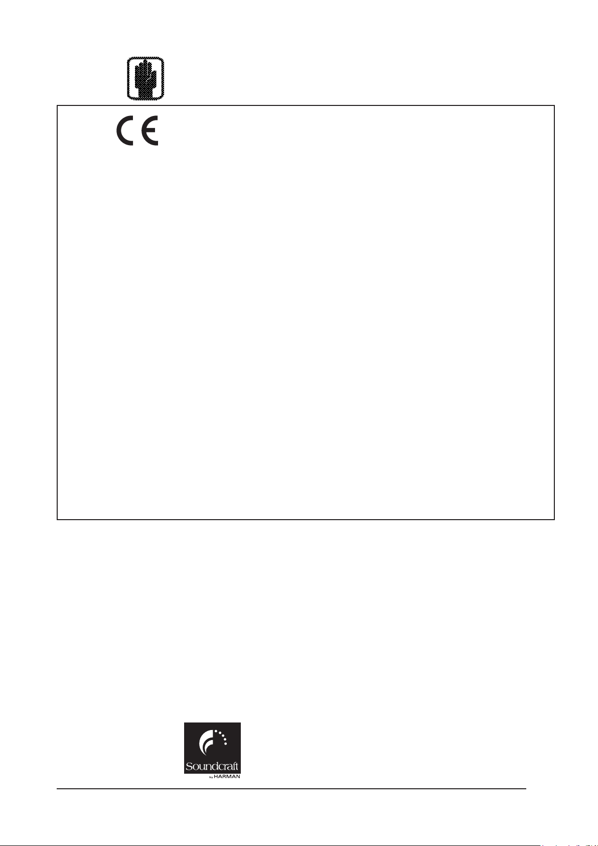
CONSOLE OVERVIEW
Bays
The Desk is based on 4 bays:
* 3 INPUT bays
* 1 MASTER bay
Figure 1-1. Console Bays.
* Each Input bay contains 8 complete Fader strips with full state overview, giving in total 24 directly
accessible Input Strips.
* The Master bay contains 8 Output Fader strips, the 3 Masters and 16 Output encoders that give a total
of 27 Output levels that can be directly controlled without changing Layers. General Functions like Snapshot, Monitoring, TB & OSC and so on are also located on the Master bay.
Soundcraft Vi4™ User GuidePage 1 - 8
Page 19
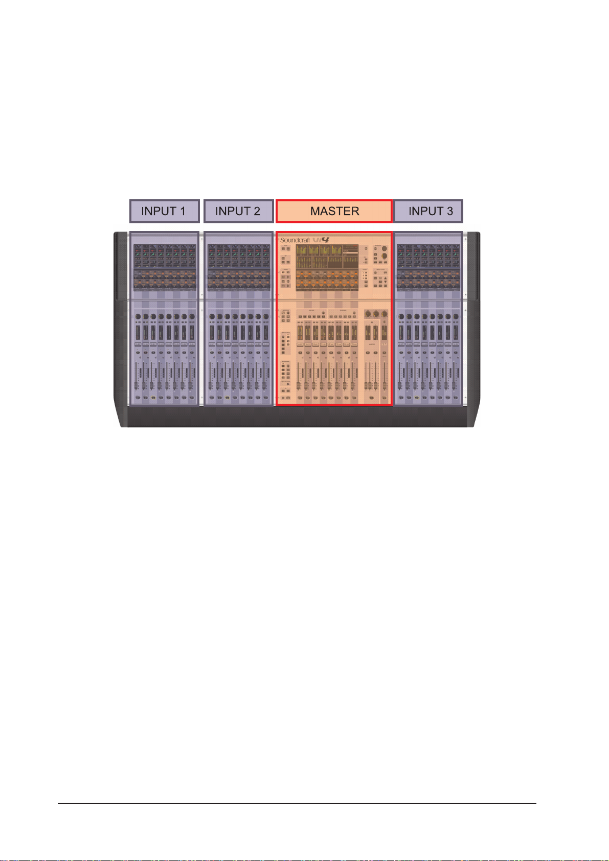
Layers
Figure 1-2. Layer Controls.
The console is able to control 48 inputs and 27 mix busses via its 24 input strips, 8 bus master strips and
the LCR masters. To do this the console has a number of layers which the user accesses via the layer
controls shown above.
Full details are given in chapter 8 of this manual.
Soundcraft Vi4™ User Guide Page 1 - 9
Page 20
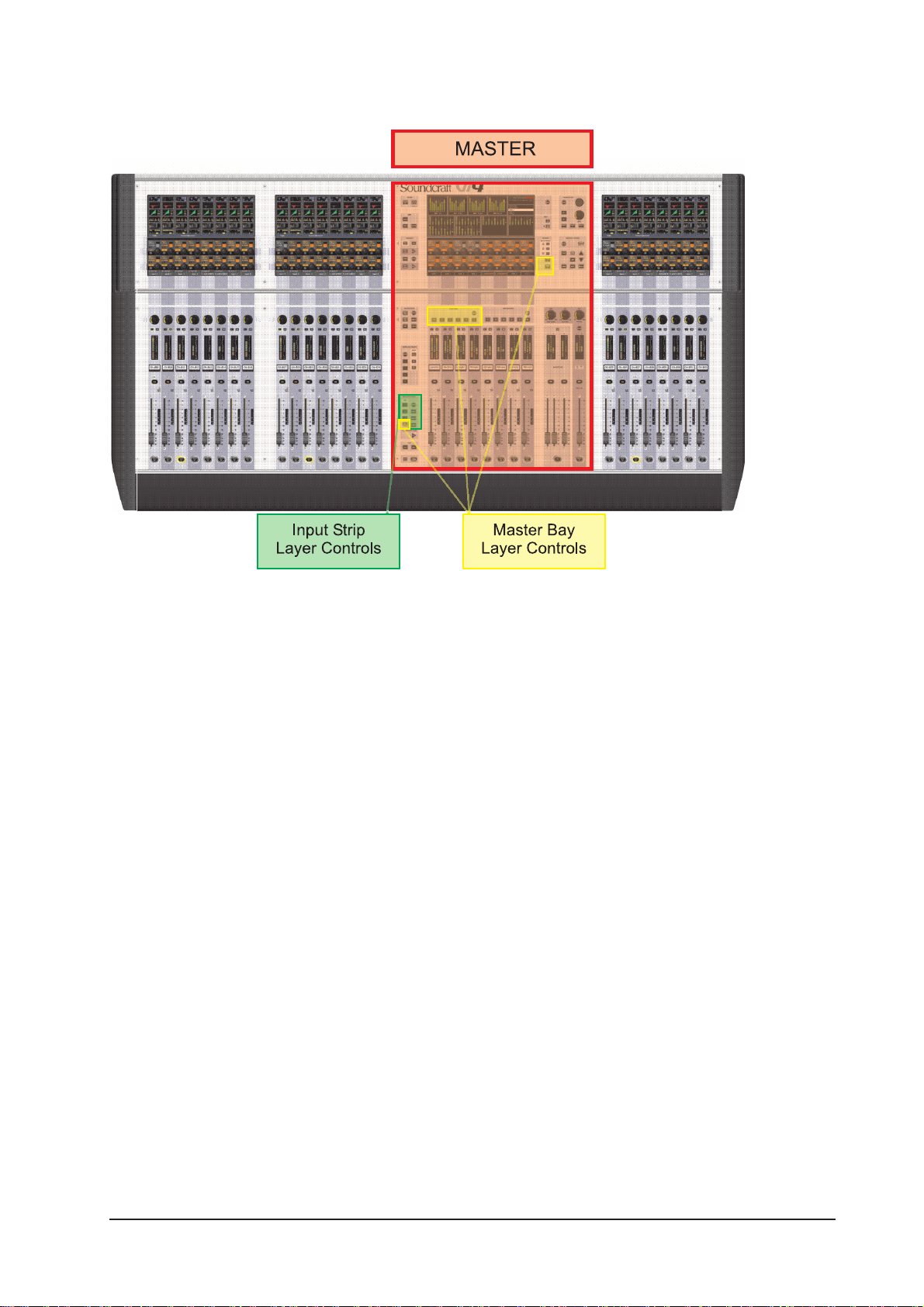
Encoders
Figure 1-3. Encoders.
* The 48 Vistonics™II row 1 and 2 encoders, including switches, are used in different modes, in which
they can change in order to show various functions in a context-sensitive way.
* In normal operation they act as Input channel related controls.
* The 24 Channel encoders are assigned with Input channel related functions.
* The 16 Vistonics™ II output encoders are normally used as Output faders and are also context sensitive.
* There are four panel-mounted encoders with LED rings: the TB/OSC Level Control encoder, and the Sold
Blend, Solo Trim & Phones Volume encoders. These are dedicated to their respective functions.
A detailed explanation of encoder use is given in chapter 7 of this manual.
Soundcraft Vi4™ User GuidePage 1 - 10
Page 21

Master Audio Functions
Figure 1-4. Master Audio Functions.
* The Monitoring system contains the functionality to listen to and monitor the audio signal at several
points in the console.
* TB/OSC system contains the Talkback functionality and the oscillator settings.
* The Meter panel provides a full overview of all 48 Input and 27 Output levels.
Soundcraft Vi4™ User Guide Page 1 - 11
Page 22

Master Control
Figure 1-5. Master Control.
* VCA/Mute Groups: this functional block contains the VCA (control groups in VCA style) and Mute Group
functions.
* Snapshot allows the console’s automated settings to be saved and recalled.
* Menu opens the Menu page where central configurations can be done.
* Copy / paste functionality can be used in different modes and speeds up repetative tasks..
* Gang is a superb feature that links channels functions together for temporary changes.
* [Power] switches the Desk on and off, while [MUTE ALL] Outputs is helpful in emergency situations.
Soundcraft Vi4™ User GuidePage 1 - 12
Page 23

SYSTEM COMPONENTS
Soundcraft Vi4™ User Guide Page 2 - 1
Page 24
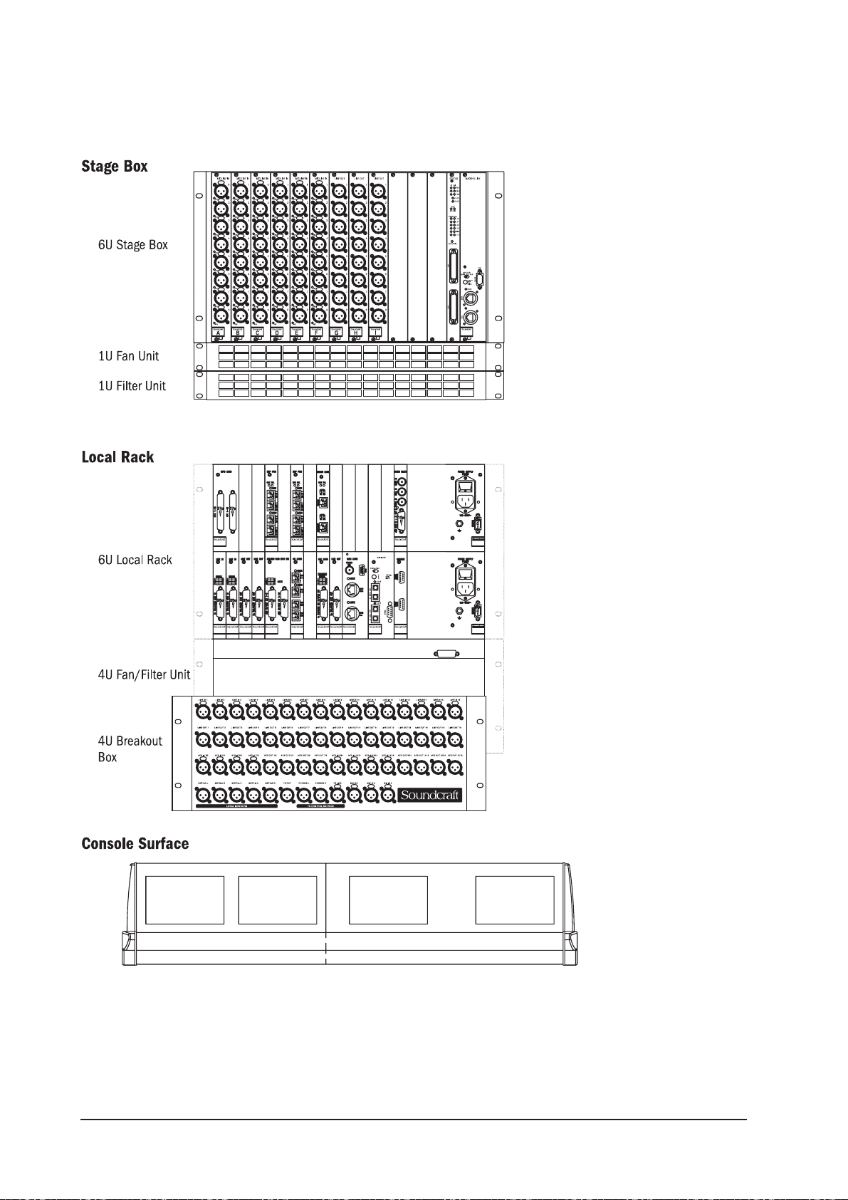
SYSTEM HARDWARE OVERVIEW
Figure 2-1. The System’s Three Component Parts.
Soundcraft Vi4™ User GuidePage 2 - 2
Page 25
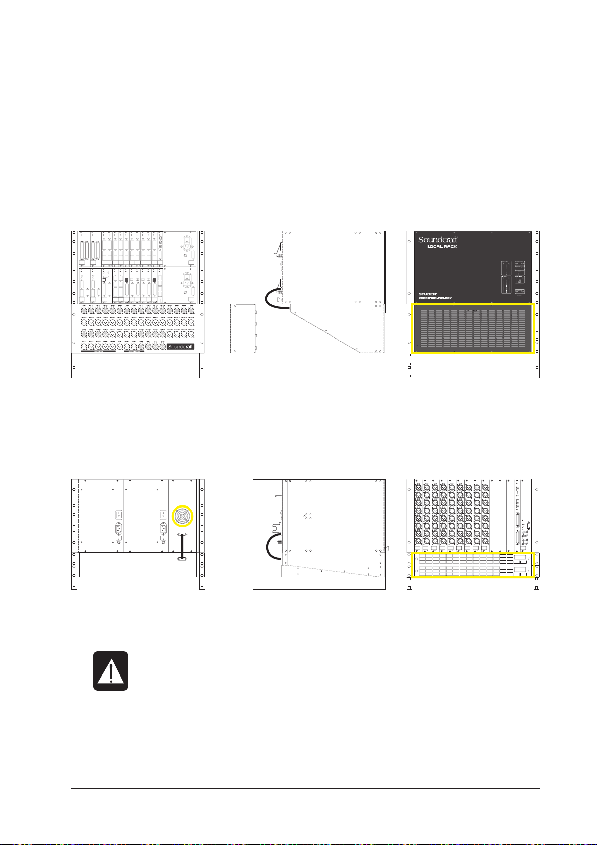
NOTE ON INSTALLATION OF THE COOLING FANS/FILTERS
The Stage Box and Local Rack may be ordered already fitted into flight cases, in which case the cooling
fans/filters will already be located correctly as shown in the diagrams below.
If the system has been ordered without flightcases, in order that it can be permanently installed, please
ensure that the cooling fans/filters are located as shown below.
Local Rack
Figure 2-2a: Layout Of Local Rack.
Stage Box
Figure 2-2b: Layout Of Stage Box.
NOTE: Ensure fan units on Local Rack and Stagebox are connected and operational.
The filters are outlined in yellow in the figures above.
CLEAN FILTERS REGULARLY!
Soundcraft Vi4™ User Guide Page 2 - 3
Page 26
THE CONSOLE REAR CONNECTORS
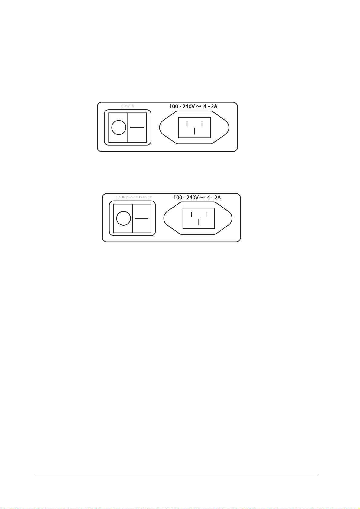
Mains Power Supply Inlet
The mains input is via an IEC connector, with an associated switch, as shown below. This feeds power to the
primary PSU.
Figure 2-3a: Main Primary Supply Inlet.
An optional redundant primary supply may also be fitted. Its inlet connector is as shown below.
Figure 2-3b: Redundant Primary Supply Inlet.
Audio And Data Rearcon
MIDI Connectors
These are provided by the usual 5-pin DIN connectors.
HiQNet™ Connector
This is an XLR-housed EtherCon connector.
USB Connectors
Use one of these to connect a PC-type keyboard. There is another USB connector on the front panel. A
memory stick can be used with either of these two free connectors.
Talkback Mic
This connector is a parallel connection to the front-panel talkback mic connector, and has an associated
48V switch for use if the microphone used requires phantom power.
TB Link, Phones L & R and Control Data
This group of four sockets (3 XLRs and an XLR-housed EtherCon connector) are used to link the console’s
control surface to the Local Rack. The cable to do this (part number RL0267-01) is supplied with the
system. The function of each of the connectors in this cable is marked with a cable sleeve.
Soundcraft Vi4™ User GuidePage 2 - 4
Page 27

Figure 2-4: Console Rearcon Panel.
Soundcraft Vi4™ User Guide Page 2 - 5
Page 28
LOCAL RACK
Local Rack Description
The Local Rack is the audio ‘brain’ of the Soundcraft Vi4™, it contains the DSP mixing processor and the
local I/O connections.
The rack consists of a 6U processing and I/O unit, developed by Studer, called the S-Core. Below this is a
4U low-noise cooling fan unit. The S-Core itself consists of two sections: the upper 3U section houses the
DSP mixing core, and the lower 3U section houses the local audio I/O and also the connections to the
remote Stage Box.
The audio processing inside the S-Core is independent of the control surface. This means that the audio
will continue to pass even if the control surface is switched off or disconnected from the core.
How It Works
The control surface sends control data to the Bridge Card, which is a communication and processing hub
situated in the centre of the top 3U section of the Local Rack. The Bridge Card interprets the control data
and sends internal data to the two DSP Pro cards and the FX Card (when fitted). These cards actually
process the audio. The audio input and output connections to the DSP cards are made via 4 short CAT 5
patch cables, which connect the DSP cards with the I/O rack in the lower 3U section of the core.
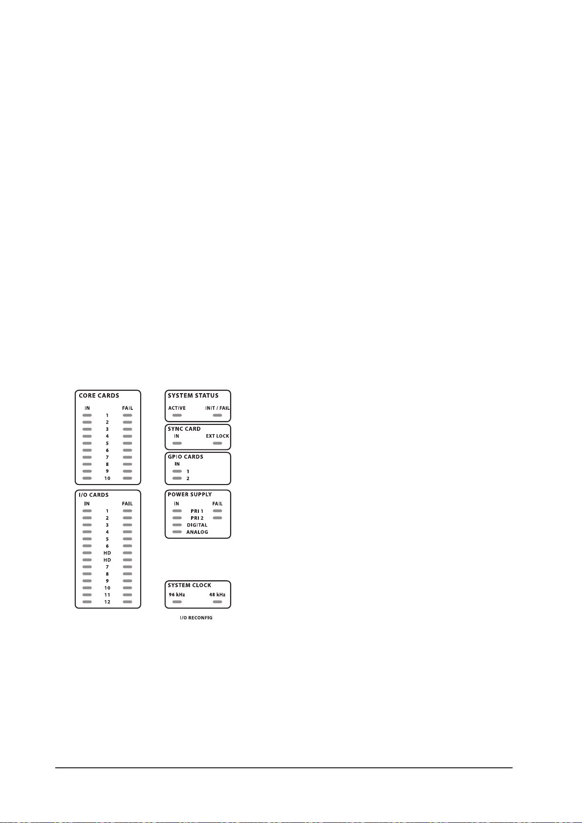
Front Panel
The front panel contains the Status LED array.
Figure 2-5: Status LEDs.
These LEDs give an at-a-glance indication that the Local Rack is functioning correctly, or that an error
condition has occured. An illuminated green LED indicates the presence of a card, an illuminated red LED
warns of a card error.
Note that there is a RECONFIG button behind a small hole at the bottom right of the panel. When pressed
with a small screwdriver or similar a reset is applied to the lower row of cards in the local rack: this will
force a re-polling of the loaded cards to reconfigure the console. This needs to be done only if the card
configuration has been changed.
Soundcraft Vi4™ User GuidePage 2 - 6
Page 29

Local Rack Rear
The rear of the Local Rack gives access to the cards in the card frame, and to the XLR breakout box.
Primary Power Supply
The primary power supply connects directly to the IEC inlet and provides a full range ac inlet, converting
100V to 240V ac to 24V dc. The Local Rack can hold up to two power supplies, providing seamless redundancy for those that require it. The rack fan control connection is also provided by one of the power supplies.
XLR Breakout Box
This provides connectors for analogue and AES/EBU audio, and interfaces to the Line In cards, Line Out
cards, Mic card and AES/EBU Card within the Local Rack card frame. All the connectors on the Breakout
Box are of the XLR type.
It is possible to order the console without this part, in this case the user will have to provide suitable
cabling and connectors to interface with the appropriate Local Rack cards. A complete pin list is given later
in this chapter.
The Breakout Box connector labelling references are used by the patching system (see chapter 11) when
the user wishes to patch the connectors to input channels or output busses.
Audio I/O Cards
The following cards are supported.
1 X Mic/Line Input card providing four electronically balanced Mic/Line Input channels, each
with digitally-controlled analogue gain, a 80Hz low-cut filter, and phantom power.
2 X Line Input cards, each providing eight line input channels.
3 X Line Output cards, each providing eight line output channels.
1 X AES I/O card, providing 16 AES input channels and 16 AES output channels.
1 X MADI Stage Box interface card ( normally Cat 5, but it can optionally be replaced by an
optical MADI card).
1 X Optical MADI card, providing 64 MADI input and 64 MADI output channels.
See page 2-10 for more details.
Soundcraft Vi4™ User Guide Page 2 - 7
Page 30

Local Rack Rear View
The rear view is shown below. Note that the last remaining connector from the console surface (the RJ45
ethernet connector) goes into the top socket on the bridge card.
Figure 2-6: Local Rack Rear View.
Soundcraft Vi4™ User GuidePage 2 - 8
Page 31

Local Rack Audio Pinouts
Soundcraft Vi4™ User Guide Page 2 - 9
Page 32

Card Function Overview
The local rack card frame contains the following components.
(Top Row)
GPIO Card with Relay Contacts
Provides a second, independent set of GPIO, which will be controlled by the GPIO page of the Control
Surface. The inputs are opto-isolated and the outputs are SPST relay contacts. For a pin-out list see chapter 16.
Bridge Card
Provides the connection from the Local Rack to the Control Surface. Houses a QNX embedded processing
system which controls all the audio processing in the rack.
DSP Pro (2 off)
Houses 12 x Hammerhead SHARC chips, which process all audio for the system.
Audio Clock
Provides clock connection to external equipment, both in and out. The wordclock input options are Video
clock, standard wordclock or AES/EBU sync clock. Any of these can be used as a wordclock source for the
console. The console permanently outputs standard wordclock and AES/EBU wordclock for sync purposes.
(Bottom Row)
Line In
Each card provides 8 x transformer isolated analogue inputs at line level. The card has a signal present
indicator for each input. Analogue to digital conversion is handled by a 24 bit ADC.
Line Out
Each card provides 8 x transformer isolated analogue outputs at line level. Card provides 8 x DAC. Clock
received from backplane. The 3rd card is used for the analogue monitor outputs, and to send phones L & R
to the control surface.
AES/EBU Card Input SRC
Card handles 8 x AES input and 8 x AES output. Inputs are sample rate converted so no external clock is
required. Inputs have signal present indication. Sample Rate Conversion (SRC) can be disabled using
internal jumpers if required.
HD Card
Communicates with the first DSP Pro on the top row of cards. It passes digital audio along with control
data and status information about the cards loaded into the frame. Each pair of links can handle up to 96
channels in both directions. The HD card is responsible for working out what cards are loaded into the
system and configuring it accordingly. The RECONFIG button on the front panel of the Local Rack will force
a re-polling of the loaded cards to reconfigure the console.
Mic Card
Provides 4 x Mic input for Talkback and local Mic input. The card has 8 indicators, 4 indicators for signal
present at the mic input and 4 indicators for the phantom power status.
MADI Card 1
This card is used to connect the Local Rack to the Stagebox. This card passes up to 64 channels of audio
in each direction between the stagebox and local rack, normally configured as 64 ins and 32 outs. The
card also sends control data to the stagebox, as well as receiving information about the status of the
stagebox cards. The second input on the card can be used to increase sample rate to 96kHz (this will also
require additional DSP and isn’t available yet) or provide redundancy. It also carries clock and control data.
The 9-pin D-type connector can carry independent RS422 serial data from local rack to stagebox. Lock
LED indicates clock lock between local rack and stagebox. Wordclock output can be used as a W/C source
when connecting two consoles to one Stagebox.
MADI Card 2
A second MADI card is fitted to the right of the first card. This second card is used for connection to an
external MADI device, such as a MADI recorder, and will always be fitted with optical connectors. It is
possible to select either 56ch or 64ch MADI mode, depending on the connected device.
Merger Card
The D-type connectors on this card are not used. This card is used only for internal communications.
Soundcraft Vi4™ User GuidePage 2 - 10
Page 33

Breakout Box
The breakout box provides connections for 16 line inputs, 16 line outputs, 16 AES/EBU input channels, 16
AES/EBU output channels, 5 local monitor outputs, a talkback output, 3 mic inputs, and 3 connectors for
the link cable to the control surface.
Figure 2-7: XLR
Breakout Box.
Soundcraft Vi4™ User Guide Page 2 - 11
Page 34

Cat 5 Breakout Panel
Note that this panel was not
fitted to early models.
Figure 2-8: Cat 5 Breakout Panel.
Soundcraft Vi4™ User GuidePage 2 - 12
Page 35

STAGE BOX
The Stage Box contains 12 Slots (only 9 are used in a Vi4™) for 6U-high Audio I/O Cards, a GPIO/LED
Card and the MADI HD Card which contains the Stage Box-to-Local Rack connection.
Slots are labelled from left to right A-L (A-I for a Vi4), and the connectors on the cards are numbered from
top to bottom 1-8. These labelling references are used by the patching system (see chapter 11) when the
user wishes to patch the connectors to input channels or output busses.
The primary power supplies and the ventilation monitoring connector can be found on the rear panel.
Stage Box Description
Primary power supply
The primary power supply connects directly to the IEC inlet and provides a full range ac inlet, converting
100V to 240V ac to 24V dc. The Stage box can hold up to two power supplies, providing redundancy for
those that require it.
Audio I/O Cards
The following cards are supported.
6 X Mic/Line Input cards each providing eight electronically balanced Mic/Line Input channels,
each with digitally-controlled analogue gain, a 20dB pad, a 80Hz low-cut filter, and phantom
power.
3 X Line Output cards, each providing eight line output channels.
Optional Cards
AES Input card, providing 8 AES input channels (replaces 1 Mic/Line Input card).
AES Output card, providing 8 AES output channels (replaces 1 Mic/Line Output card).
Card Function Overview
Input card
Input cards handle 8 x mic amp, phantom power, pad, analogue low pass filter, phase reverse and A to D.
The card has an internal ID, which indicates whether it is input or output and analogue or digital. This
means that the system can automatically recognise if the card configuration has been changed.
Output Card
Output cards handle 8 x D to A. The card has a set of relays, which will mute the outputs if the power fails.
The module type is identified by the internal ID of the module.
Normally 3 output cards are fitted, giving 24 outputs, however, more cards, up to a maximum of 8 cards
giving 64 outputs, can be fitted if input cards are removed.
LED/GPIO/Status card.
Handles GPIO, which is controlled remotely from the Control Surface. The inputs are on opto-isolators and
the outputs are open collector transistor outputs. The card also has status indicators for power rails, clock
status and IO, and a RECONFIG button which must be pressed if the card configuration has been changed.
MADI HD link card
This card provides audio and control connection with the Local Rack via MADI. The corresponding MADI
card in the Local Rack transmits the clock for the Stagebox down the MADI stream. The second input on
the card can be used to increase the sample rate to 96KHz, provide a redundant connection to the Local
rack or to connect to a second system if two consoles are to be used for a monitor/FOH configuration. The
Soundcraft Vi4™ User Guide Page 2 - 13
Page 36

MADI card indicates its clock status using the lock LED on the card. An RS422 link output is also fitted,
allowing RS422 data to be transmitted via a ‘pipeline’ within the MADI stream from a corresponding port
on the Local Rack to allow remote RS422 control. This RS422 port can also be used to control the mic
preamp gain in the Stagebox if it is in stand-alone mode or digital snake mode.
Redundant MADI Cable Operation
The system can be used with either a single cable connected to the MAIN or AUX ports (usually MAIN), or,
for additional security, two cables can be used to provide fully-automatic redundant operation. The 3position INPUT SEL toggle switch on the Stagebox MADI card determines the mode of operation.
It is very important that this switch is set correctly!
For single cable operation: the switch must be set to either ‘MAIN’ or ‘AUX’, depending on which socket is
being used.
For dual redundant operation: the switch MUST be set to the ‘RED’ position.
In redundant mode, the system will automatically switch to the other cable if a fault is detected on one
cable. Note that it will then stay on the second cable even if the connection is restored on the first cable.
This is to prevent intermittent switching.
NOTE: Do NOT operate with the switch in ‘RED’ mode when only one cable is being used.
Although this may appear to work, audio may not be restored if the cable is temporarily
unplugged.
Soundcraft Vi4™ User GuidePage 2 - 14
Page 37
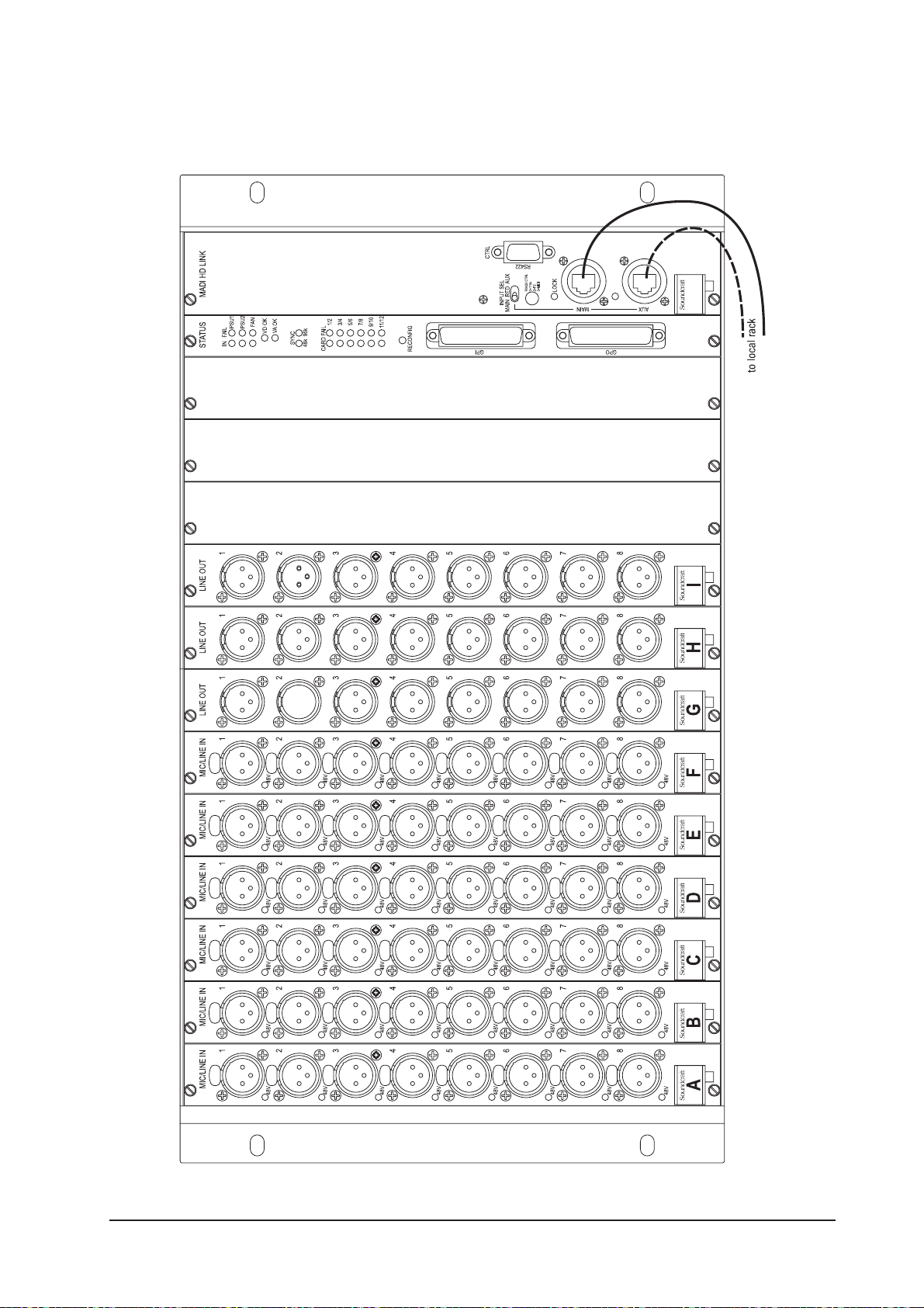
Front Panel
Figure 2-9: Stage Box Front Panel.
Soundcraft Vi4™ User Guide Page 2 - 15
Page 38
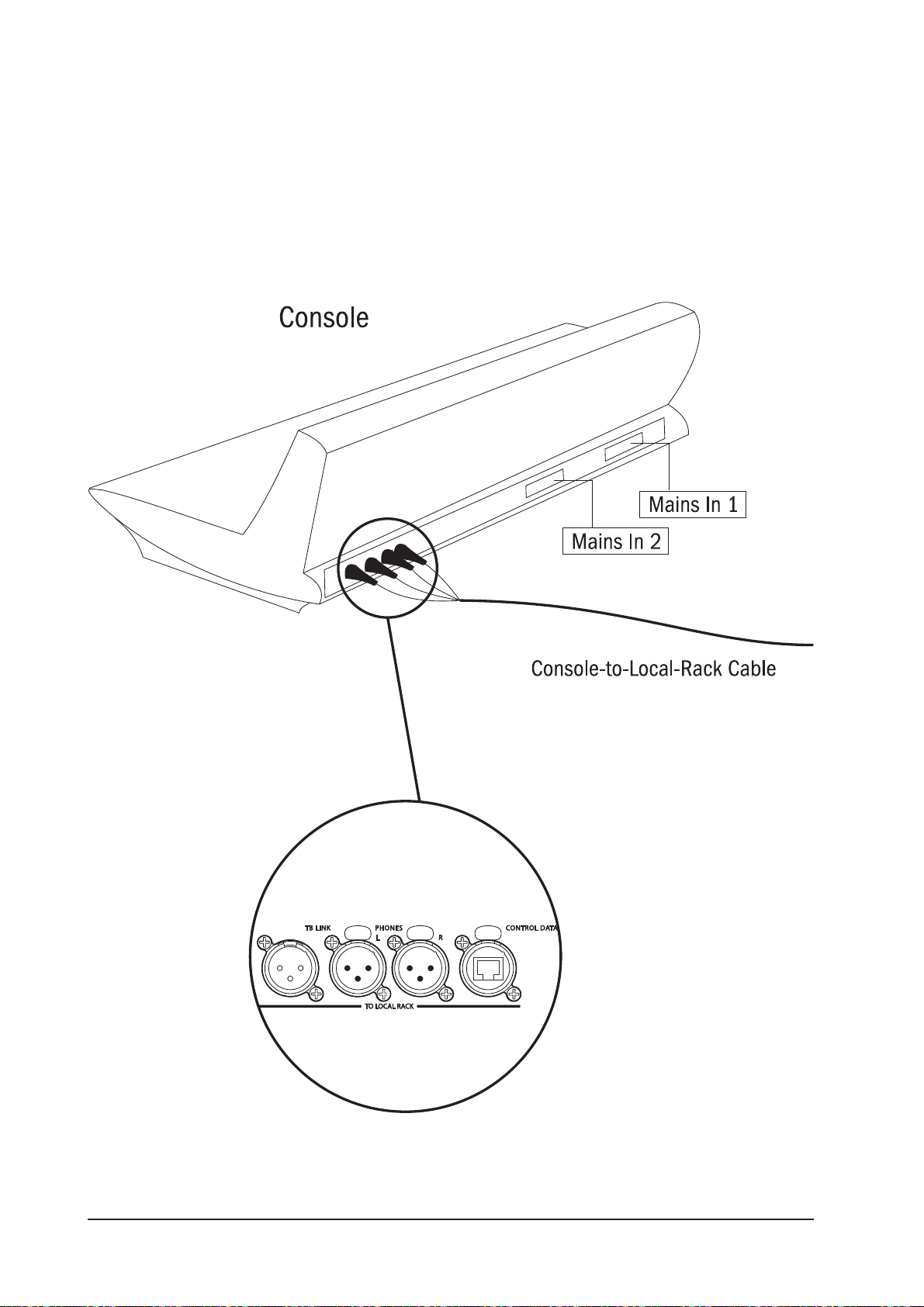
CONNECTING THE PARTS OF THE SYSTEM
Figure 2-10a: System Interconnections.
Soundcraft Vi4™ User GuidePage 2 - 16
Page 39

NOTE: Ensure fan units on Local Rack and Stagebox are connected and operational.
CLEAN FILTERS REGULARLY!
Figure 2-10b: System Interconnections.
Soundcraft Vi4™ User Guide Page 2 - 17
Page 40

Soundcraft Vi4™ User GuidePage 2 - 18
Page 41

OPERATION OVERVIEW
GENERAL RULES
* Pressing a [SETUP] key whilst in that SETUP function will exit that function immediately.
* Vistonics™ {EXIT} buttons close the page immediately.
* Parameter changes made by the user are processed immediately.
* Grey-out is used to show that an audio function block is bypassed.
* In order to allow the pre-setting of parameters it is possible to change the parameters and
states even if the block is greyed out, e.g. EQ filters can be switched on/off and parameters can
be changed even if the Equaliser is switched off with the EQ {IN} key.
CONVENTIONS USED IN THIS MANUAL
Three types of brackets are used to indicate the type of control being refered to.
[ ] is used to indicate a panel-mounted key or encoder.
{ } is used to indicate a Vistonics™ (VST) key or encoder.
< > is used to indicate a button on a touch-screen.
SCREENS
Input Screens
The Input Screens are divided into logical areas and fields as shown below.
Figure 3-1: Input Bay Screen Areas and Fields.
Note: each TFT screen may have up to 4 permanently bright or permanently dark pixels, and still be within
the TFT screen manufacturer’s specifications.
Soundcraft Vi4™ User Guide Page 3 - 1
Page 42

Screen Colour Codes
The following table shows the colours used in their corresponding context:
Function Colour
Audio Processing
Input Functions Blue
Equaliser Red
Filter Dark Blue
Gate,Comp,Lim,De-ess Green
Pan, Dir Out, Insert Yellow
Oscillator Gold
Monitoring Lilac
Busses
Aux Orange
Audio Group Green
Matrix Cyan
VCA/MG Indication
VCA 1..8 Blue
VCA 9..16 Pink
Mute Group Patch Red
Input Patch Blue
Output Patch Red
Control Grey
For the Soundcraft FaderGlow™ colours see chapter 17. Soundcraft FaderGlow™ (Pat. Pend.) is a unique
feature that gives the user an additional level of status overview, and can significantly reduce operating
errors.
Soundcraft Vi4™ User GuidePage 3 - 2
Page 43

VISTONICS II™ KNOBS
If a function is assigned to the button, the state is indicated like this:
Figure 3-2a: VST Button Status Indication.
If the button can open a configuration page in the Touch area it looks like this:
Figure 3-2b: VST Buttons Which Can Open A Configuration Page.
AUDIO FUNCTION STATES
If an audio function block is disabled, with the background of the field changed to grey, the button indication will change to a darker colour.
Figure 3-2c: Active/Disabled Functions.
MOMENTARY/LATCHING CONTROL ACTION
The physical keys on the desk have both a momentary and a latching action. If a key is pressed and
released within approximately one half of a second, the control will latch. If the key is held down for
longer, and then released, the control will return to its original state as the key is released.
The keys on the Vistonics area also operate in the same way.
The touch-screen buttons/areas operate in a latching mode only.
Soundcraft Vi4™ User Guide Page 3 - 3
Page 44

SOLO/SEL KEYS
The [SOLO/SEL] keys operate in two modes.
The default function is to enable the SOLO path from its channel or bus to the monitoring system.
However, if a touch-area page is open, pressing a [SOLO/SEL] from another channel (within its own bay of
eight channels) moves the touch-area page to this new channel.
LABELLING
General
Labelling can be done with the on-screen keyboard or an external USB keyboard.
The on-screen keyboard is context sensitive and shows only the allowed character and symbols.
Fig 3-3: The On-screen Keyboard.
Soundcraft Vi4™ User GuidePage 3 - 4
Page 45
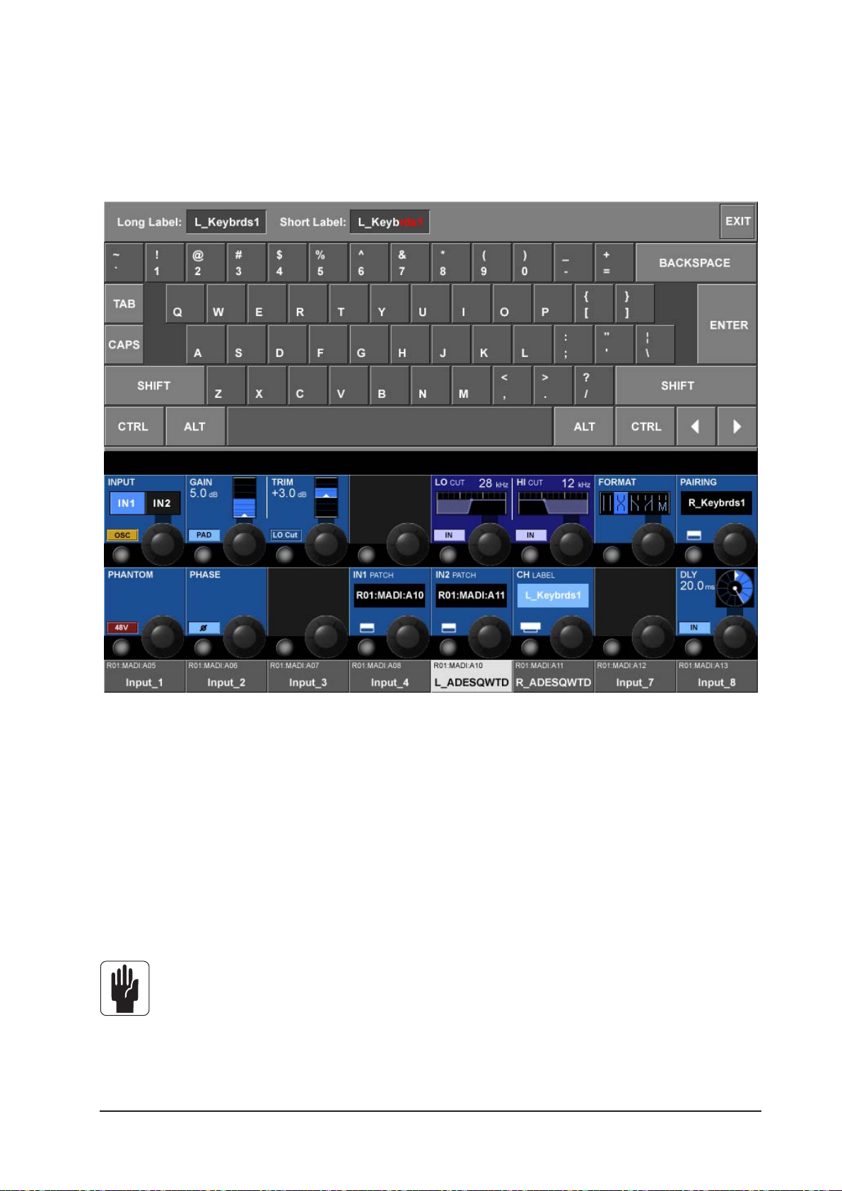
Channel Labels
By default the channels are labelled CH-1 to CH-48.
Soundcraft Vi4™ uses long labels for the Screens and short labels for the LCDs. Long labels can contain
up to 10 characters, whereas short labels are restricted to 6 characters.
Figure 3-4: The Channel Label Page.
Changing The Channel Label
* Press the <INPUT> touch field to open the Input Page.
* Enter the channel label page by pressing {CH LABEL} on the Input Page.
* Type the long name (only valid characters are possible).
* Adjust the short name if necessary by touching the <Short Label> on the screen or by using
<TAB>.
* Leave the page with <ENTER>, or by pressing {CH LABEL} again.
<TAB> toggles the cursor between long and short fields.
Soundcraft Vi4™ User Guide Page 3 - 5
Page 46
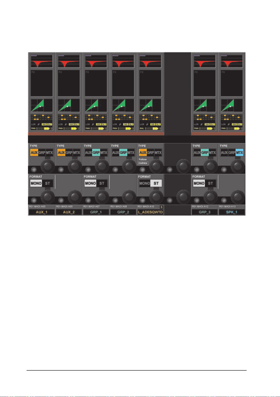
BUS CONFIGURATION
The most important configuration of the Soundcraft Vi4™ is the bus configuration, and this is done using
the [ALL BUSSES] view on the three input bays.
Figure 3-5: The Input Screen If [ALL BUSSES] Layer Is Active.
The TYPE field can be set to one of three values: AUX, GRP or MTX, the encoder is used to change the Bus
Type. If Aux is selected and if the format field, see below, is set to stereo then the {CHPAN} field enables
the stereo Aux send signal to follow channel pan, rather than have its own pan control.
The FORMAT field (only odd busses) is available for Aux and Grp busses. The field can be set to Mono or
Stereo. The Encoder changes the setting of the Audio Format field. If the field is set to stereo the next even
numbered bus will not be shown.
In the ALL BUSSES Layer, all 24 Busses are showed from left to right on the three input bays. i.e., Bus 1 is
mapped to the left-most strip, while bus 24 is mapped to the right-most strip of the Control Surface.
Vi4 supports the following Bus Types:
· AUX Mono
· AUX Stereo
· Group Mono
· Group Stereo
· Matrix Mono
Soundcraft Vi4™ User GuidePage 3 - 6
Page 47

GANG
General
Gang is a very helpful feature to speed up operations that influence functions on multiple input channels,
or on output busses, in the same way.
For example, if Input Channels are ganged, then a parameter change of a function will be applied to all
other ganged channels in an offset manner. For example, adjusting any rotary parameter or fader within a
gang will add that offset to, or subtract it from, all other channels in the gang. Pressing a switch will
change all other channels whose switches are not currently in the resulting state, to that state. From that
point on, further presses will result in all switches changing mode together.
Creating A Gang
* Activate the GANG Mode with [GANG], the [GANG] key will glow blue (see Figure 1-4 for the
location of the [GANG] key).
* Add/remove a channel by pressing channel’s [SOLO/SEL] key. The [SOLO/SEL] becomes blue
if the channel is in the gang.
* ADD/Remove a range by pressing the first and last channel [SOLO/SEL] together.
Switching-Off Gang Mode
Once a Gang has been created, it can be de-activated by switching the [GANG] key off. The
[SOLO/SEL] keys will return to normal solo operation. The Gang will be stored however, and can
be re-activated for further use at any time. Gang member settings are independent of the
console’s snapshot automation, but are stored when the console is powered off.
Clearing A Gang
* Press and hold any active (blue) [SOLO/SEL]
or
* Leave the GANG mode with [GANG].
Gang All Input Channels
* Press and release [GANG] to switch Gang mode on, and then press and hold [GANG] until all
of the Input [SOLO/SEL] keys turn blue. This selects all channels (including hidden layers) to the
gang. When all of the Inputs are Ganged their [SOLO/SEL] keys turn blue.
Entering Gang Mode does not cancel any solos of any type that are active at the time. The Solo
system continues to work as it was when Gang Mode was switched ON. The amber ‘Solo’
illumination of the Solo/Sel switches cannot be seen whilst gang mode is ON.
It is recomended that Gangs are cleared down after use, particularly if GANG ALL is used.
Soundcraft Vi4™ User Guide Page 3 - 7
Page 48

Soundcraft Vi4™ User GuidePage 3 - 8
Page 49
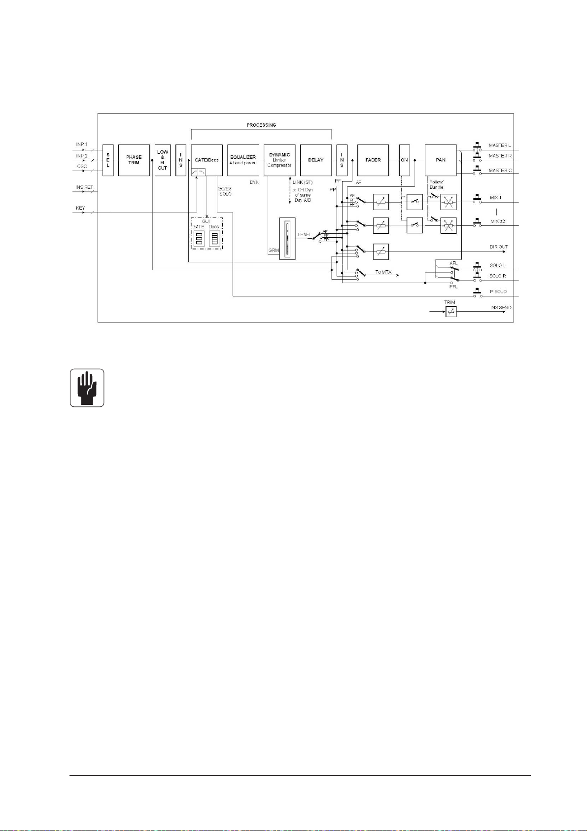
SIGNAL FLOW
MONO INPUT
CHANNEL 1 TO 48
Figure 4-1: The Signal Flow In An Input Channel.
INPUT
Only one of the two insert points can be used per channel at any time.
Soundcraft Vi4™ User Guide Page 4 - 1
Page 50

INPUT CHANNEL STRIP
Figure 4-2. Input Channel Strip.
The Level Meter reads from -36dB to +18db, The GRM (Gain Reduction Meter) reads from -1 to -20dB.
Soundcraft Vi4™ User GuidePage 4 - 2
Page 51
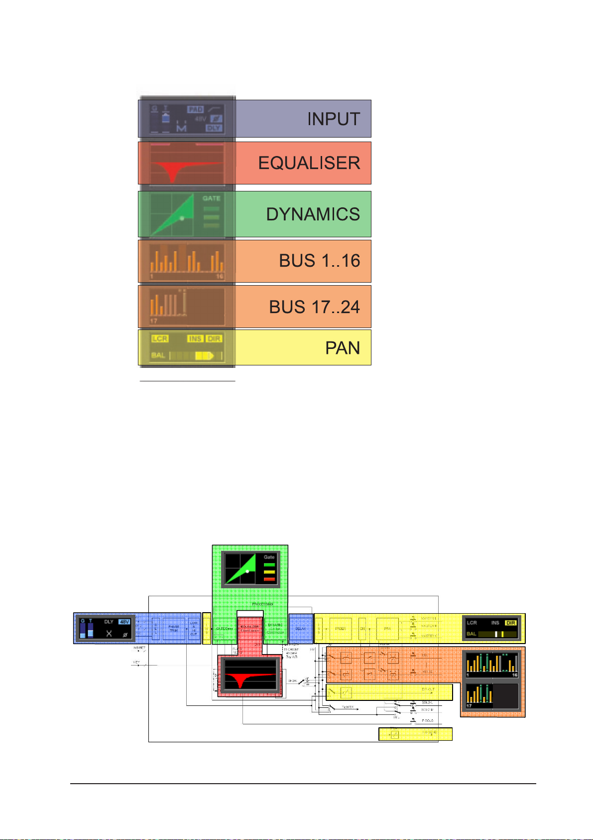
INPUT CHANNEL TOUCH FIELDS
Figure 4-3.
Change A Parameter Of An Input Channel
* Press the desired touch field, the corresponding VST area will open,
* change the parameter.
* Press the touch field again to go back the default VST view OR
* Press another touch field.
MONO INPUT
CHANNEL 1 TO 48
Figure 4-4: the relationship between touch fields and channel functions.
Soundcraft Vi4™ User Guide Page 4 - 3
Page 52

INPUT
Figure 4-5: The Input Page.
INPUT field
Select source IN1 or IN2. If OSC is active the central oscillator is patched to this channel and the selector
is disabled.
Pressing the {IN1 PATCH} or {IN2 PATCH} VST config key opens the Input Patch Configuration page.
Figure 4-6. Input Patch Configuration Page.
Soundcraft Vi4™ User GuidePage 4 - 4
Page 53

GAIN field
{encoder} adjusts the analogue input gain in the range from +15 dB to +70 dB.
{PAD} reduces the input sensitivity by 20 dB.
TRIM field
Encoder adjusts the digital Input Gain in the range +18/-36 dB
{LO CUT} inserts the pre AD converter analogue low cut filter (only analogue inputs).
LO CUT field
Encoder adjusts the Low cut frequency in the range 20 to 600 Hz.
{IN} switches the Low Cut filter in and out.
HI CUT field
Encoder adjusts the High cut frequency in the range 1k to 20kHz.
{IN} switches the Hi Cut filter in and out.
FORMAT field
If the Channel is paired, the Encoder adjusts the Stereo format, which can be:
LR / RL / LL / RR / MONO.
If the channel is not paired, this field is not displayed.
PAIRING field
If the Channel is paired the label of the paired channel is visible.
{Its VST config button} enters the pairing configuration.
PHANTOM field
{48V} enables the Phantom Power (+ 48 V) for the XLR patched to this input.
PHASE field
{INV} inverts the phase of this channel (180 Degrees).
IN1 PATCH field
Displays the source name that is patched to IN1.
{Its VST config button} opens the IN1 patch page (see chapter 10).
IN2 PATCH field
Displays the Source name that is patched to IN2.
{Its VST config button} opens the IN2 patch page (see chapter 10).
CH Label field
Displays the channel label.
{Its VST config button} opens the channel label configuration page.
DLY field
Encoder changes the input delay in the range 0.. 100 mS.
{IN} enables the delay function.
Soundcraft Vi4™ User Guide Page 4 - 5
Page 54
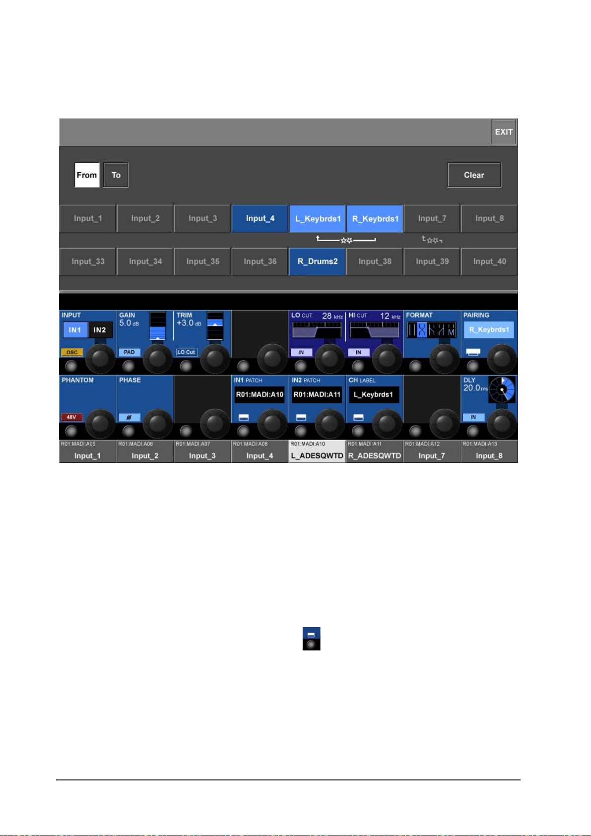
STEREO CONFIGURATION
Pairing of input channels
Figure 4-7: The Pairing Page.
The available channels on the two fixed Layers A (upper row) and B (lower row) are displayed on the touch
screen.
Pairing candidates are the unused left and right neighbours and the vertical neighbour in the same Bay.
Existing Pairings will be shown greyed out. It is not possible to pair with a channel in the next bay.
HINT: Selecting an input channel [SOLO/SEL] moves this page to the desired channel in the corresponding
bay.
Pair An input Channel
* Enter the pairing page by pressing {PAIRING} in the Input Page, all possible pairing candidates will be shown.
* Select the desired pairing candidate, all channel parameters will be copied to the paring
candidate, links will be set. The meter overview in Master screen shows the pairing information
* Optionally change the copy direction with <FROM>, <TO>.
* Leave the page with {EXIT} or {PAIRING}.
HINT: If a destination candidate is used in another pair you must first release that pairing.
Soundcraft Vi4™ User GuidePage 4 - 6
Page 55

Stereo Busses
Busses can be configured to work as a Stereo Bus. In this case the Bus Master is represented in one Strip
on the surface. The advantage is that more masters can be directly accessed (rather than tying up two
Output controls).
In the Encoder section stereo bus masters also use only 1 VST Field.
Soundcraft Vi4™ User Guide Page 4 - 7
Page 56
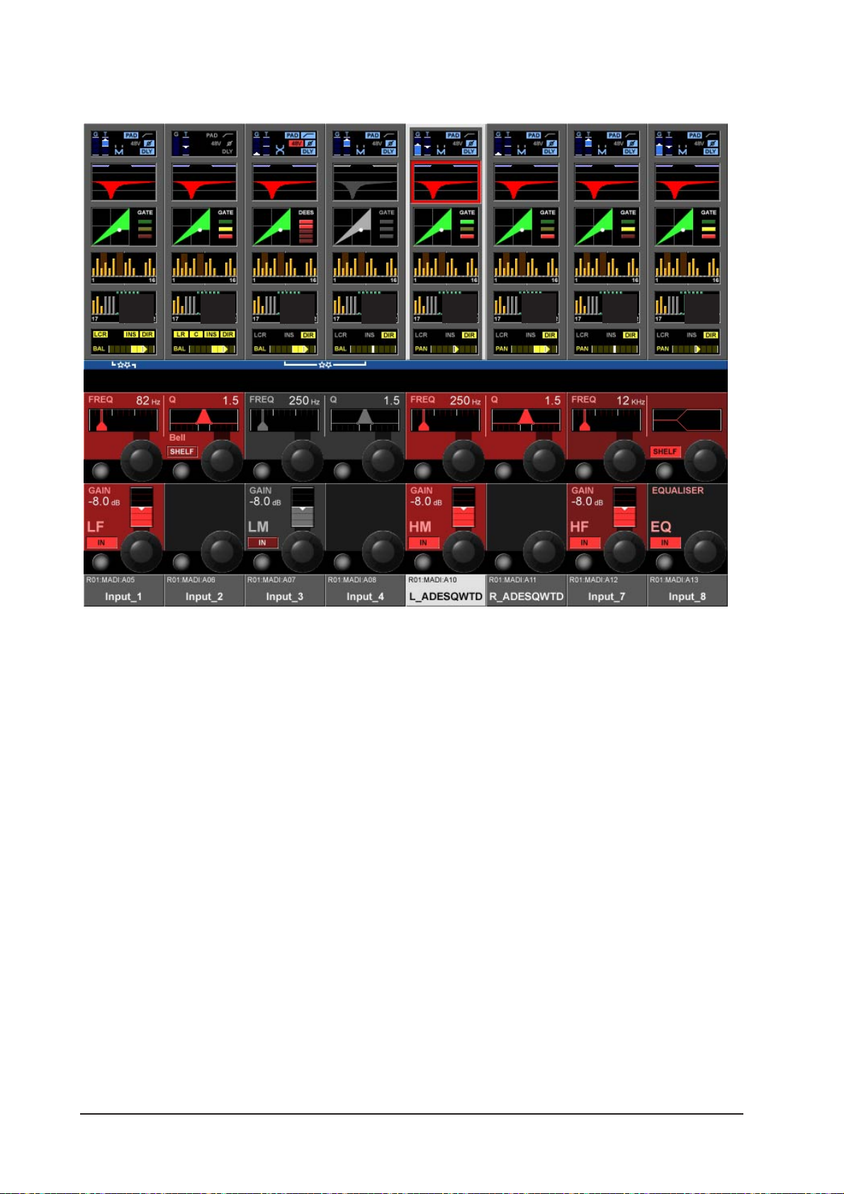
EQUALISER
Figure 4-8: The Equaliser Page.
General
The Equaliser contains 4 full parametric Bands. All four parametric Equaliser Bands operates over the full
frequency range. The characteristics of the LF and HF bands can also be set to SHELF mode.
The red Equaliser Graph in the Equaliser touch field represents the overall frequency curve. It contains:
* Low Cut and High Cut Filters
* Equaliser with the 4 bands
Additionally, two blue bars at the top of the Equaliser touch field clearly indicate the Low and High Cut filter
frequencies. (The filters are adjusted from within the INPUT Vistonics™ II page.)
Soundcraft Vi4™ User GuidePage 4 - 8
Page 57

Equaliser Band Highlight
If you touch one or more parameter encoders, the corresponding Equaliser band(s) will be indicated by the
red overall graph being overwritten with a white graph that represents only the touched band(s). This is
useful for identifying which part of a curve is associated with which EQ bands. The representation will
return to the default when you leave the page.
Figure 4-9: The Equaliser Page After Touching An LF Encoder.
BAND Field
All four bands contain a GAIN, FREQ, Q encoder and an IN switch.
GAIN
Encoder adjusts the Gain in the range +/- 18 dB. {IN} enables the Equaliser band.
FREQ
Encoder adjusts the frequency in the range 20 Hz .. 20 kHz.
Q
Encoder adjusts the Q (Width) in the range 0.7 .. 15 only for BELL Mode.
IN Switch
{IN} enables this Equaliser band.
SHELF Switch
{SHELF} changes the response characteristic to SHELF. (12dB/oct)
EQUALISER Field
{IN} enables the full Equaliser section (without filters). For preparation, all Parameters including the band
IN switches can be set, even if the Equaliser is switched off.
Soundcraft Vi4™ User Guide Page 4 - 9
Page 58

DYNAMICS
Figure 4-10: The Dynamic Page In GATE Mode.
General
The Dynamics section contains a GATE with key filter a Compressor and a Limiter. Alternatively the Gate
can be set to operate in De-esser mode.
GATE Function
The Gate contains a side-chain input with filters, a Key listen SOLO and it can also operate in ducking
mode.
State Indication
The Gate status is indicated on the right side of the Dynamics touch field:
* ON green
* HOLD yellow
* OFF red
Soundcraft Vi4™ User GuidePage 4 - 10
Page 59

THRS Field
Encoder adjusts the threshold value between -40 db to +18db.
{IN} enables the GATE.
ATCK field
Encoder adjusts the attack time in the range 10µS to 957mS.
{INV} sets the GATE to inverse mode (ducking mode).
HLD field
Encoder adjusts the hold time in the range 2.2mS to 2S.
REL field
Encoder adjusts the release time in the range 2.2mS to 3.7S.
RNG field
Encoder adjusts the attenuation RNG value in the range 0 to -60dB.
{SC SOLO} switches the side-chain signal to the solo bus.
LO CUT
Encoder adjusts the frequency of the side-chain signal Lo Cut filter.
{IN} enables the Low cut filter.
HI CUT
Encoder adjusts the frequency of the side-chain signal Hi Cut filter.
{EXT Key} enables an external key signal, which is selected via the {KEY} key associated with the MODE
field below; otherwise the internal signal is used for triggering the gate.
MODE field
Encoder switches the operational mode between GATE or Deesser.
{Key} opens the key signal patch page -see chapter 10.
Soundcraft Vi4™ User Guide Page 4 - 11
Page 60
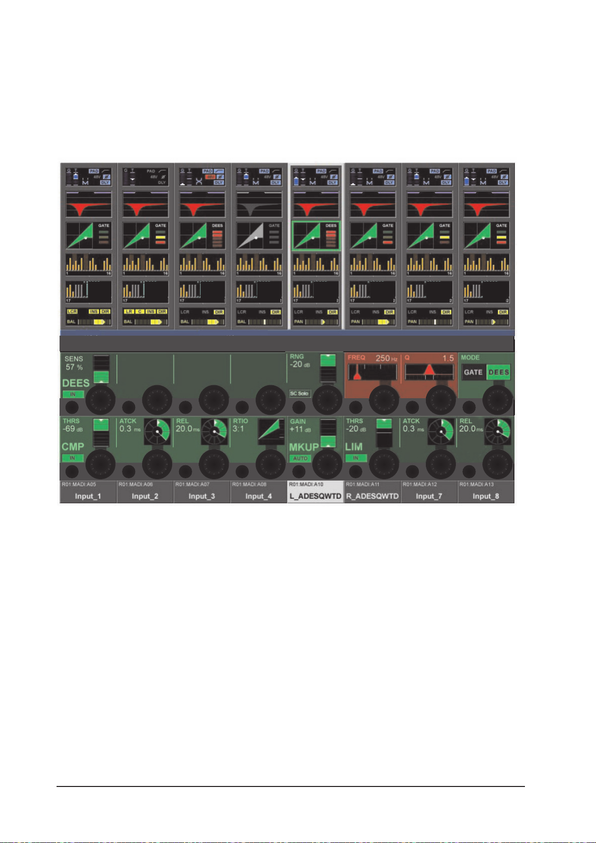
DE-ESS Function
A de-esser is normally used to reduce the sibilance (“s” components) in a singer’s voice.
Soundcraft Vi4™ includes a real de-esser function that works as dynamically controlled filter. The filter can
be set using the FREQ and Q encoders.
If the de-esser is active, the signal level will be reduced only in the band set by the filters, when the signal
in this band exceeds the required threshold.
Figure 4-11: The Dynamic Page In DE-ESS Mode.
Gain Reduction Meter
The De-esser GRM, a 5-segment bar-graph is located on the right-hand side of the dynamic touch field on
the screen.
SENS Field
Encoder adjusts the effect’s sensitivity value between 0 – 100%.
{IN} enables the DE-ESSER.
ES SOLO Field
{ES SOLO} switches the filtered processing signal to the solo bus.
FREQ Field
Encoder adjusts the centre frequency of the dynamic de-esser filter.
Q Field
Encoder adjusts the width of the dynamic de-esser filter.
MODE
Encoder selects the operational mode, either GATE or De-esser.
Soundcraft Vi4™ User GuidePage 4 - 12
Page 61

COMPRESSOR Function
THRS Field
Encoder adjusts the threshold value between -40 db to +18dB.
{IN} enables the COMPRESSOR.
ATCK Field
Encoder adjusts the attack time in the range 0.5mS to 98.6mS.
REL field
Encoder adjusts the release time in the range 5.5mS to 5S.
Ratio field
Encoder adjusts the ratio in the range 1:1 to 20:1.
LIMITER Function
THRS Field
Encoder adjusts the threshold value between -40 db to +18dB.
{IN} enables the LIMITER.
ATCK Field
Encoder adjusts the attack time in the range 10µS to 98.6mS.
REL Field
Encoder adjusts the release time in the range 5.5mS to 957mS.
MKUP
Makeup adjusts the overall output level from the Limiter and Compressor sections.
GAIN
Encoder manually adjusts the output level to compensate for gain reduction.
{AUTO} automatically adjusts the output level depending on the settingd of the THRS and RATIO controls.
Soundcraft Vi4™ User Guide Page 4 - 13
Page 62

BUS
Figure 4-12: The Bus Page.
General
The first Bus page contains the controls for busses 1-16, while the second page contains the controls for
busses 17-24.
What these fields look like depends on the Bus configuration.
AUX (Mono)
Encoder adjusts the send level to this BUS. Pre indicates the PRE/post state. {ON} enables the send.
AUX (Stereo)
Left Encoder adjusts the send level to both busses, while the right encoder adjusts the pan to these
busses.
HINT: If the channel is paired, the right encoder adjusts the Balance to the Busses. If the ‘follow channel
pan’ option was activated in the bus configuration, there will be no function on the right encoder.
PRE indicates the pre/post state. {ON} enables the send.
GRP (Mono)
{ON} routes the signal to this bus.
GRP (Stereo)
{ON} route the signals to both busses.
Empty
If a bus has been configured as a Matrix, it is not visible in this page.
Soundcraft Vi4™ User GuidePage 4 - 14
Page 63
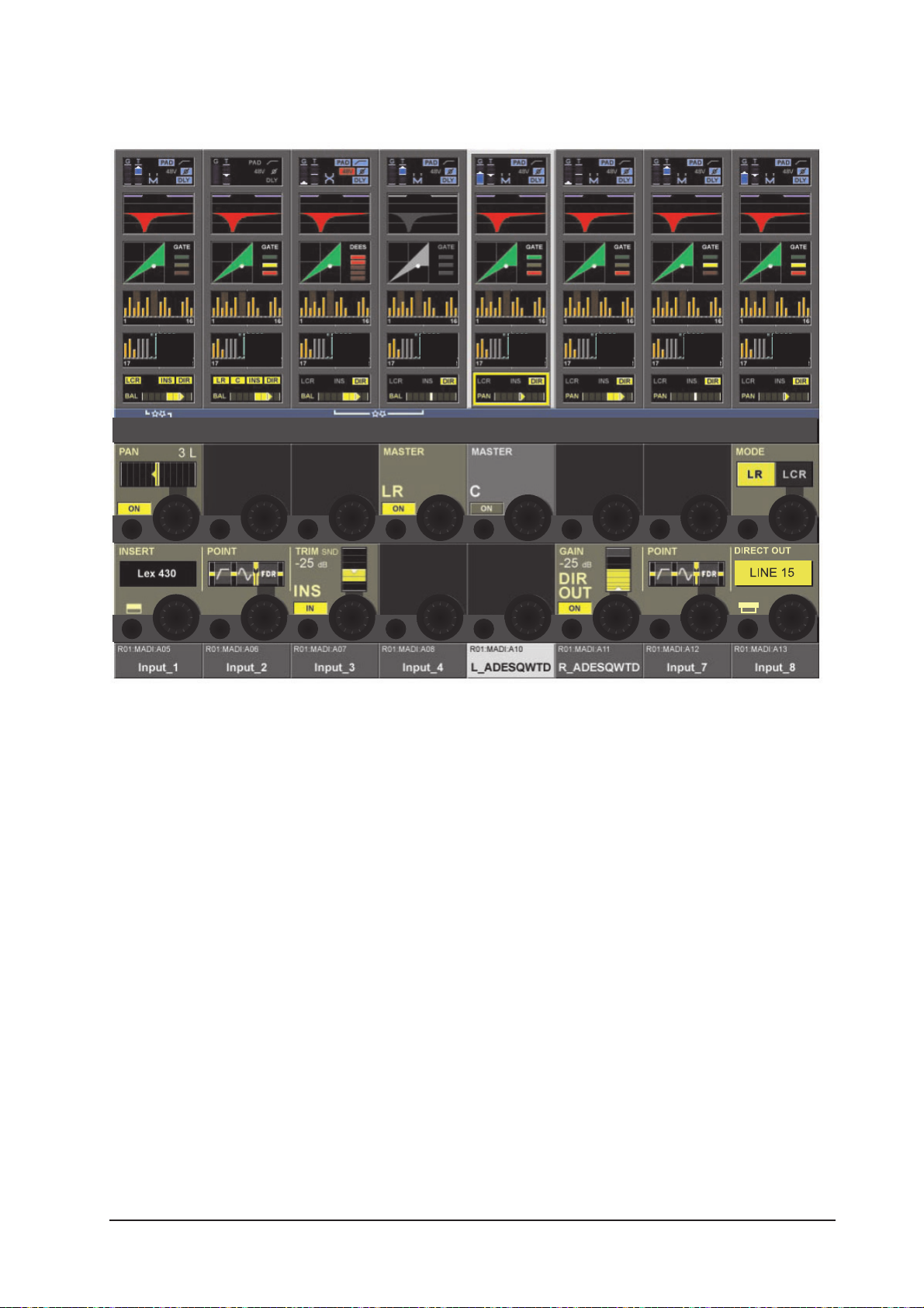
PANNING
Figure 4-13: The Panning Page In LR Mode.
General
This page contains the output functions of the input channel. This contains the panning, the routing to the
masters, the insert point and the direct out function. The Pan can work in LR or in LCR mode. In LCR mode
an additional width function is available.
PAN Function LR Mode
PAN Field
Encoder sets the channel pan to the masters. If the channel is paired, the balance can be adjusted.
See Audio Format / Pan / Panning, on pages 4-17 & 4-18.
MASTER LR
{ON} routes the channel signal to the Left and Right master busses.
MASTER C
{ON} routes the channel signal to the Centre master bus.
MODE
Switches the pan mode between LR or LCR. This field is not available for stereo-paired inputs.
Soundcraft Vi4™ User Guide Page 4 - 15
Page 64

PAN Function LCR Mode
If the Pan MODE is set to LCR an additional WIDTH field is displayed. (If the channel is paired, it is not
possible to set the PAN mode to LCR.)
Figure 4-14: The Panning Section In LCR Mode.
PAN Field
Displays the pan setting. Encoder sets the channel pan to the three masters. See Audio Format / Pan /
Panning on pages 4-17 & 4-18.
WIDTH Field
In LCR mode, the encoder adjusts the level of an additional amount of signal sent to both left and right
outputs.
MASTER LCR
{ON} routes the channel signal to the Left, Right and Centre masters.
Soundcraft Vi4™ User GuidePage 4 - 16
Page 65

AUDIO FORMAT
General
The Soundcraft Vi4™ can handle three types of audio format:
* MONO
* STEREO
* LCR
Input Channels
Soundcraft Vi4 contains 48 MONO Input channels. A STEREO Input can be built by horizontally or vertically
pairing two input channels in the same bay.
Vertically and horizontally pairing can be used at the same time. See Pairing of input channels.
Mix Busses
The 24 MONO Busses can be configured to work as Mono or as odd/even paired Stereo Busses.
Masters
The three Masters L, R, C can be used as LCR Masters if the Pan mode of the input channels is set to LCR
mode, otherwise L and R works as stereo output and the C can be used as an independent Mono Master.
Soundcraft Vi4™ User Guide Page 4 - 17
Page 66

PAN/BAL
The following table shows the destination level in relation to the PAN/BAL settings
MODE Left position Middle position Right position
Left Right Left Right Left Right
PAN OFF - 3 dB - 3 dB - 3 dB - 3 dB - 3 dB - 3 dB
PAN ON 0 dB - ∝ - 3 dB - 3 dB - ∝ 0 dB
BAL OFF 0 dB 0 dB 0 dB 0 dB 0 dB 0 dB
BAL ON + 3 dB - ∝ 0 dB 0 dB - ∝ + 3dB
HINT: If the PAN or BAL function is switched off, the gain is the same as if you had set the Encoder to the
middle position.
If all TRIM, Faders and so on are in the 0dB position the outputs from the L and the R Masters are 3 dB
lower than a MONO Input signal.
MONO PAN STEREO BAL
Figure 4-15a. Figure 4-15b.
If a panning mode is set to LCR, then the WIDTH function will become active.
LCR PAN with WIDTH = 0
L
C
R
0 dB
-3 dB
Figure 4-15c.
LCR PAN with WIDTH = 100
LCR PAN with WIDTH = 100
Figure 4-15d.
Soundcraft Vi4™ User GuidePage 4 - 18
Page 67

INSERT Function
Refer to Figure 4-13.
INSERT Field
Displays the label of the selected insert from the pool.
{Its VST config button}opens the Insert Pool select page.
Refer to page 10-6 for details about setting-up the Insert Pool.
POINT Field
Displays the actual point where the Insert is placed in the channel.
Encoder changes the point between:
* Pre Processing (EQ&DYN)
* Pre Fader.
TRIM Field
Encoder trims the insert send level in the range +- 18 dB.
{IN} activates the Insert.
Direct Out Function
GAIN field
Encoder sets the Direct Output send level.
{ON} activates the Direct Output.
POINT Field
Displays the actual point in the channel’s signal path from where the Direct Output is taken.
Encoder selects the point between:
* Pre Filter
* Pre Processing
* Pre Fader
* Post Fader.
PATCH Field
Displays the patched Output.
Its {VST config button} opens the Direct Output patch configuration page (see page 10-8).
Soundcraft Vi4™ User Guide Page 4 - 19
Page 68

Soundcraft Vi4™ User GuidePage 4 - 20
Page 69
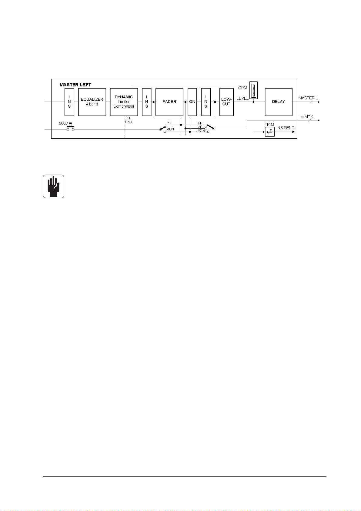
SIGNAL FLOW
Figure 5-1: The Signal Flow In An LRC Master Or A MIX Master.
Only one of the three possible insert points can be used per master at any time.
OUTPUTS
Soundcraft Vi4™ User Guide Page 5 - 1
Page 70

GENERAL
The LR and C Masters are always operated with their dedicated master fader strips in the master bay.
The parameters of these busses are controlled via the Master Processing Page (see Figure 5-2).
The Soundcraft Vi4™ allows three different ways to access, control the level of , and change the parameters of, the other 24 output busses. These are:
via the Master Bay’s Output Strips, and selecting the fader page* required,
via all of the Input Strips, using the [ALL BUSSES] key,
via the Vistonics™ buttons and encoders on the master section screen.
* For detailed information about Layering see chapter 8.
Soundcraft Vi4™ User GuidePage 5 - 2
Page 71
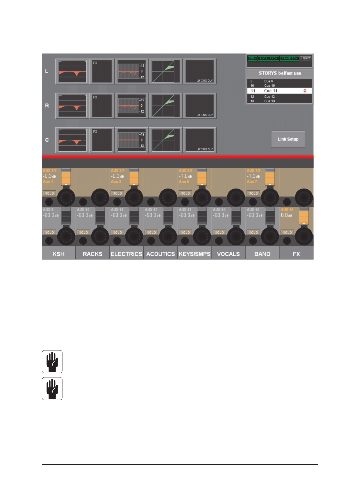
L,R & C Master Processing
Figure 5-2A: Master Screen Displaying The Master Busses Processing Page.
This page is accessed by pressing the [SEL] key which is located below the L, R & C master faders.
The Master processing fields are shown in the Meter Area of the Master Screen.
In order to change the parameters for EQ, Dynamics or Pan, the appropriate area on the touch-screen must
be pressed; doing so will open a page whose VST area is similar to the lower half of Figures 5-9, 5-10 or
5-11.
Note: When selecting the PAN area, the page which will be displayed will be similar to Figure 511 except that the PAN, MASTER LR and MASTER C fields will not be present.
Note: The output levels of the L R & C Master outputs are always controlled by their dedicated
faders.
Soundcraft Vi4™ User Guide Page 5 - 3
Page 72

MASTER EQ LINKING (V2.0 Software and above)
Figure 5-2B : Master Screen Displaying The Master Busses Processing Page with EQ Linking.
The LRC Master busses can have their Parametric and/or Graphic Equaliser sections linked for easier
adjustment. Left and Right busses can be linked, or the Centre bus can be added to the linked L&R so that
all three busses can be adjusted together. It is not possible to link Left and Centre or Right and Centre.
The linked state is indicated at all times by a pair of white ‘gear wheel’ icons between the L and R Parametric and Graphic EQ touch fields.
A similar icon with 3 ‘gear wheels’ indicates that the C bus is also linked.
To link or unlink the EQ or GEQ sections
. Press [SEL] below the LRC Master faders to open the Masters strip display.
. Press the {LINK SETUP} button in the bottom right corner of the Master strip display.
. Touch either of the L or R {EQ} touch fields to toggle the linked state on and off for the EQ.
Touch the C {EQ} field to add/subtract the C bus EQ to the linked L/R pair.
. Touch either of the L or R {GEQ} touch fields to toggle the linked state on and off for the GEQ.
Touch the C {GEQ} field to add/subtract the C bus GEQ to the linked L/R pair.
The fields that are available to be toggled in and out of the linked state are shown with a highlighted white
border around the touch field when {LINK SETUP} is active.
Note that the FX fields and the Dynamics fields of the L and R busses are permanently linked, and cannot
be toggled in the Link Setup mode.
Default settings
The settings of the EQ and GEQ Linking for the Master busses is stored in the current Show.
The links are set to ON for L,R and C busses for both EQ and GEQ, in the factory default Shows that are
supplied with the console.
Soundcraft Vi4™ User GuidePage 5 - 4
Page 73

MASTER BAY OUTPUT STRIPS
The first way of controlling and changing the parameters of the 24 output busses described earlier is as
follows.
Figure 5-3. A Master Bay Strip.
In order to select the desired output from the 24 possible choices, the correct fader page, A-C, must first
be assigned to the master bay (see Figure 8-5 for the keys). Once this is done, the user can select the
desired fader to control the output level, and pressing its [SOLO/SEL] key opens the processing Area in the
Master screen (see Figure 5-4).
HINT: [METER LOCK] must be off, otherwise the processing strip will not be displayed. If multiple
Output Solo are activated the processing for the last-pressed Master Solo is displayed.
Soundcraft Vi4™ User Guide Page 5 - 5
Page 74

Bus Master Processing
Figure 5-4: Master Screen Displaying Bus Processing Page.
The Bus Master processing is shown in the Input Meter Area of the Master Screen. In order to change the
parameters for EQ, Dynamics or Pan, the appropriate area on the touch-screen must be pressed; doing so
will open a page whose VST area is similar to the lower half of Figures 5-9, 5-10 or 5-11.
HINT: Stereo Busses are linked. Therefore the processing strip will control both channels.
Soundcraft Vi4™ User GuidePage 5 - 6
Page 75

INPUT BAY STRIP USING [ALL BUSSES]
The second method of controlling, and changing the parameters of, the 24 output busses described earlier
is as follows.
If the [ALL BUSSES] key is active (see Figure 8-6), the input strips on all of the input bays will be switched
to control the 24 output busses.
Once this is done, the user can select the desired fader to control the required output level. In addition, the
VST encoders can be used to change the bus type (Aux, Grp or Mtx) and format (Mono or Stereo).
In order to change the parameters for EQ, Dynamics or Pan, the appropriate area on the touch-screen
above the required strip must be pressed; doing so will open a page similar to Figures 5-9, 5-10 or 5-11.
Figure 5-5.Intput Bay Strip With [ALL BUSSES] Active.
Soundcraft Vi4™ User Guide Page 5 - 7
Page 76
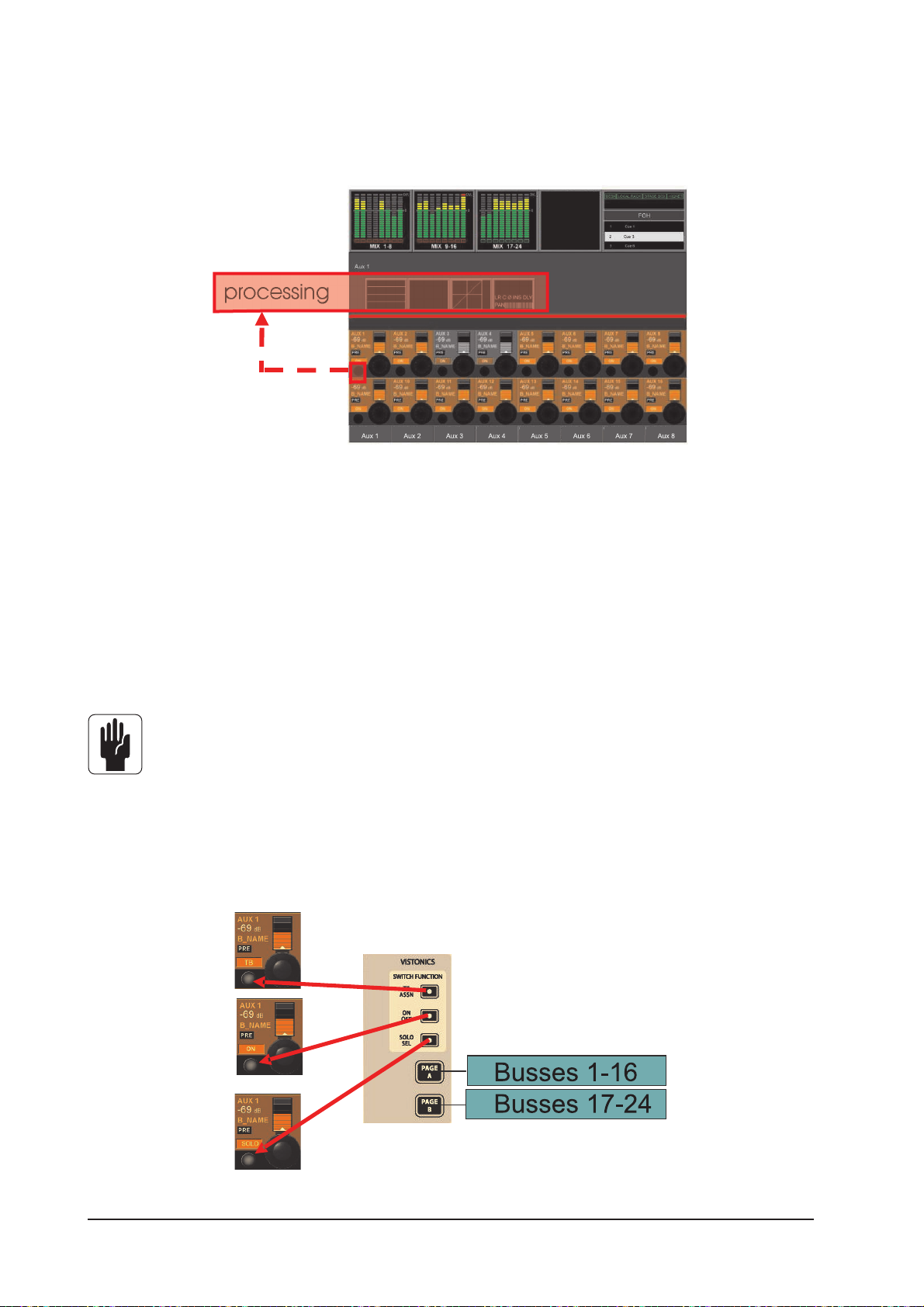
MASTER BAY VISTONICS™ ENCODERS & KEYS
The third way of controlling, and changing the parameters of, the 24 output busses described earlier is as
follows.
Figure 5-6. Output VST Switches.
The VST encoders control the levels of the displayed output busses. To select the desired range of busses
the user must press [Page A] or [Page B] to the right of the screen (see Figure 5-7). The [PAGE A] key
displays busses 1-16 in the VST area, [PAGE B] displays busses 17-24.
To change output bus parameters the user must first ensure that the [SOLO SEL] key on the VISTONICS
SWITCH FUNCTION panel is active( see Figure 5-7). When this is done pressing the {SOLO} VST key opens
the processing Area in the Master VST screen (see Figure 5-6). In order to change the parameters for EQ,
Dynamics or Pan, the appropriate area on the touch-screen must be pressed; doing so will open a page
whose VST area is similar to the lower half of Figures 5-9, 5-10 or 5-11.
HINT: [METER LOCK] must be disabled, otherwise the processing strip will not be displayed.
VST Key Function
The functionality of the VST key can be set, via the VISTONICS SWITCH FUNCTION panel,to TB Assign, ON/
OFF or SOLO/SEL, where SOLO/SEL is the default setting. The function is the same for ALL Encoders in
both pages. The [PAGE A] key displays busses 1-16 in the VST area, [PAGE B] displays busses 17-24.
Figure 5-7: VISTONICS SWITCH FUNCTION Panel.
Soundcraft Vi4™ User GuidePage 5 - 8
Page 77

CHANGING OUTPUT BUS PARAMETERS
The following pages shows bus master processing using the Input strip (All Busses layer) mode as an
example. Parameter changing is done in the same way if either of the other two ways of accessing bus
masters is used.
Changing A Parameter Of A Bus
* Press the desired touch field, the corresponding VST Area will open
* change the parameter
* Press the touch field again to go back to the default VST view
or
* Press another touch field.
Figure 5-8: The Relationship Between Touch Fields And Master Functions.
Soundcraft Vi4™ User Guide Page 5 - 9
Page 78
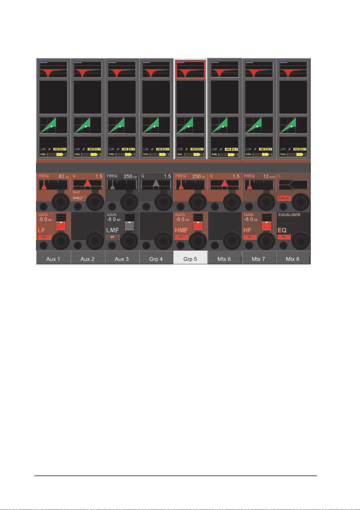
EQUALISER
Figure 5-9. Equaliser Controls.
The controls are identical to those of the input channels’ EQ.
The VST encoders and keys allow the 4-band parametric EQ to be adjusted and switched in or out of
circuit.
Soundcraft Vi4™ User GuidePage 5 - 10
Page 79

DYNAMIC
Figure 5-10. Dynamics Controls.
The controls are identical to those of the input channels, except there are no Gate or De-Esser modes
available for output busses.
Soundcraft Vi4™ User Guide Page 5 - 11
Page 80
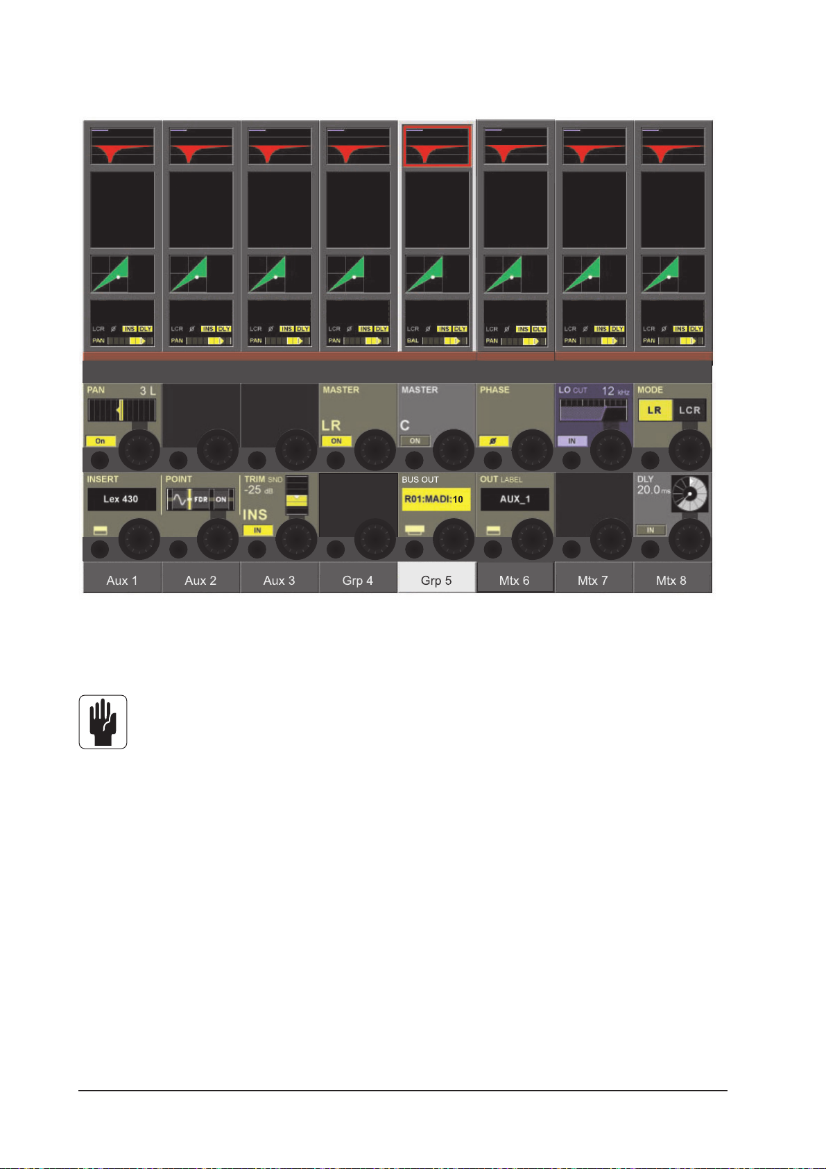
PAN
Figure 5-11. Pan.
The controls for the PAN section and Insert section are similar to those of the input channels.
Note that for L, R and C master busses, the PAN, MASTER LR and MASTER C fields are not
available.
The extra functions unique to output busses are as follows.
LOW CUT Field
The encoder adjusts the Low cut frequency in the range 20 to 600Hz.
{IN} switches the Low Cut filter in and out.
PHASE Field
{PHASE} inverts the phase at the output.
DLY Field
The encoder changes the output delay in the range 0 - 1000 mS.
{IN} enables the delay function.
Soundcraft Vi4™ User GuidePage 5 - 12
Page 81

MATRIX
SIGNAL FLOW
Figure 6-1: Matrix Signal Flow.
Only one of up to 16 matrix paths is visible in figure 6-1.
FUNCTION
Instead of a simple Output matrix Soundcraft Vi4™ has a built-in freely-configurable matrix that can have
up to 16 Outputs (mono).
Each matrix output is a mix of up to 24 configurable sources and contains full processing including Equaliser, compressor/limiter and Delay.
Sources to the Matrix can be signals from busses, channel direct outputs or inputs.
Hint: The sources for each matrix out can also be individually patched, the matrix can be utilized as 16
different mixers, each with up to 24 inputs, with output processing.
Soundcraft Vi4™ User Guide Page 6 - 1
Page 82

MTX master name
MTX Source
MTX Point
[function]
Strip number (1..24)
[ON] Source
FADER (Source)
[SOLO/SEL]
[Isolate]
Level meter & GRM
VCA display
FADER GLOW
Figure 6-2: Matrix Strip.
Soundcraft Vi4™ User GuidePage 6 - 2
Page 83
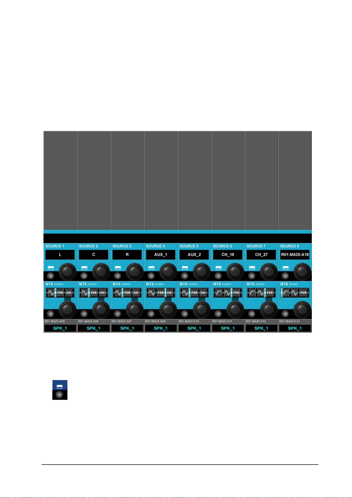
Adjusting A Matrix Send Level
Ensure that the [ALL BUSSES] key is NOT selected.
Press the [SOLO/SEL] on a matrix master. All the input bays will change to the matrix contributions view
and the Faderglow™ illuminates with the matrix colour. The input strip [ON] keys act as ON for the matrix
send signals. The fader adjusts the contribution level of the desired source (1..24).
MATRIX CONFIGURATION
This screen opens on all 3 input bays after pressing SOLO/SEL on a matrix master.
Figure 6-3:Matrix Configuration Page
SOURCE field
Displays the patched source.
The key opens the Matrix patch configuration page - see chapter 11.
Soundcraft Vi4™ User Guide Page 6 - 3
Page 84

MTX Point Field
The encoder changes the point from where the matrix source signal is taken.
Which points are available depends on the Source selected.
MTX Input Pre Filter Pre- Pre Fader Post Fader Post ON
Source Processing
Input *
Direct OUT * * * *
Master bus * * *
Soundcraft Vi4™ User GuidePage 6 - 4
Page 85
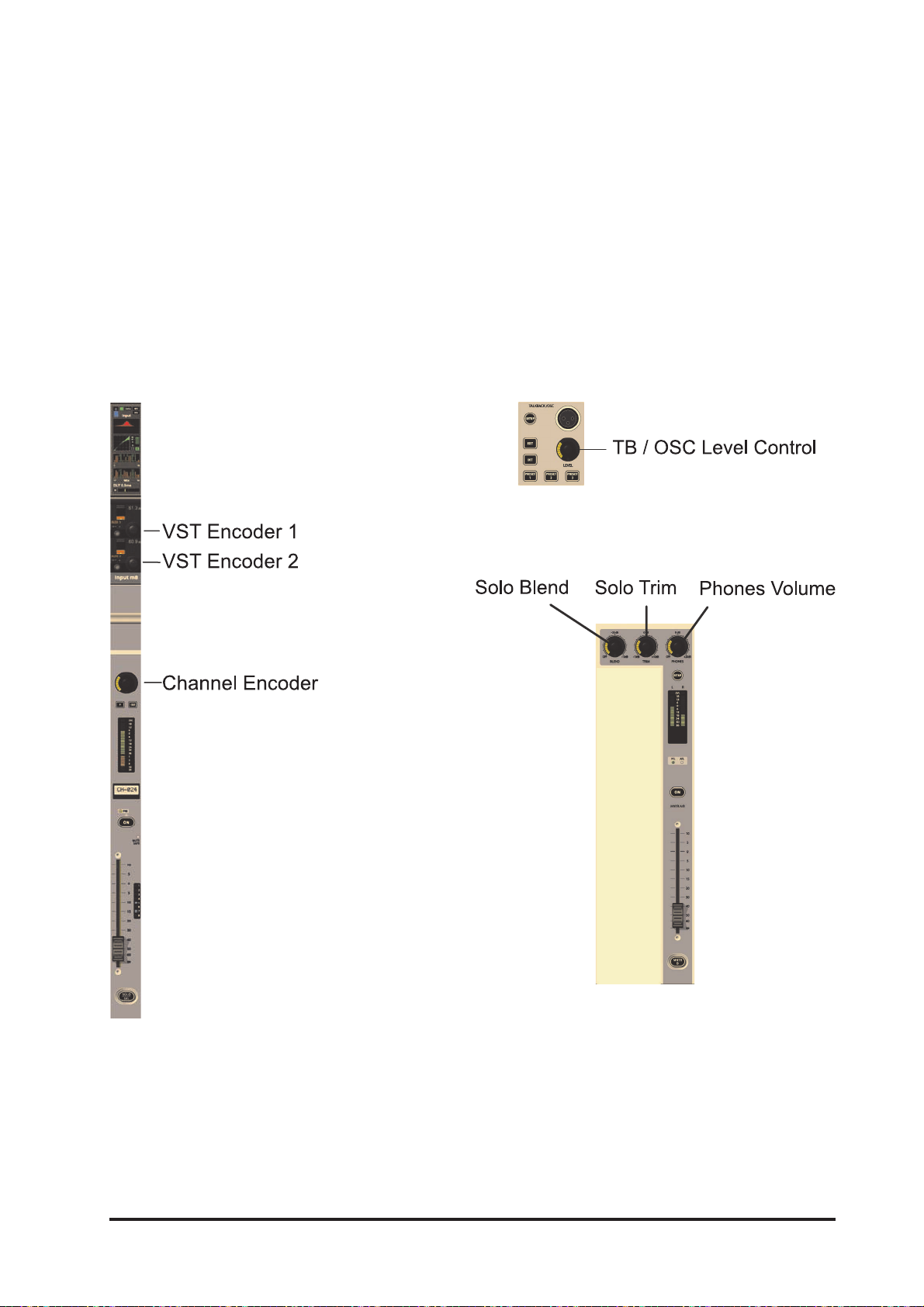
ENCODERS
GENERAL INTRODUCTION
Each input channel strip contains three encoders (see Figure 7-1A): encoder 1 & encoder 2 are located in
the VST fields in the lower screen area, the channel encoder is located at the top of the fader area, and
has an LED ring to indicate its parameter state. Each of these encoders can control different parameters,
depending on the settings of other parts of the console.
The master section has 16 VST encoders and 4 panel-mounted encoders with LED rings (see Figure 7-1B):
the TB/OSC Level Control encoder, and the Sold Blend, Solo Trim & Phones Volume encoders. These last
four are dedicated to their respective functions.
Figure 7-1B: Master Section Panel Encoders.Figure 7-1A: Input Channel Strip Encoders.
Soundcraft Vi4™ User Guide Page 7 - 1
Page 86
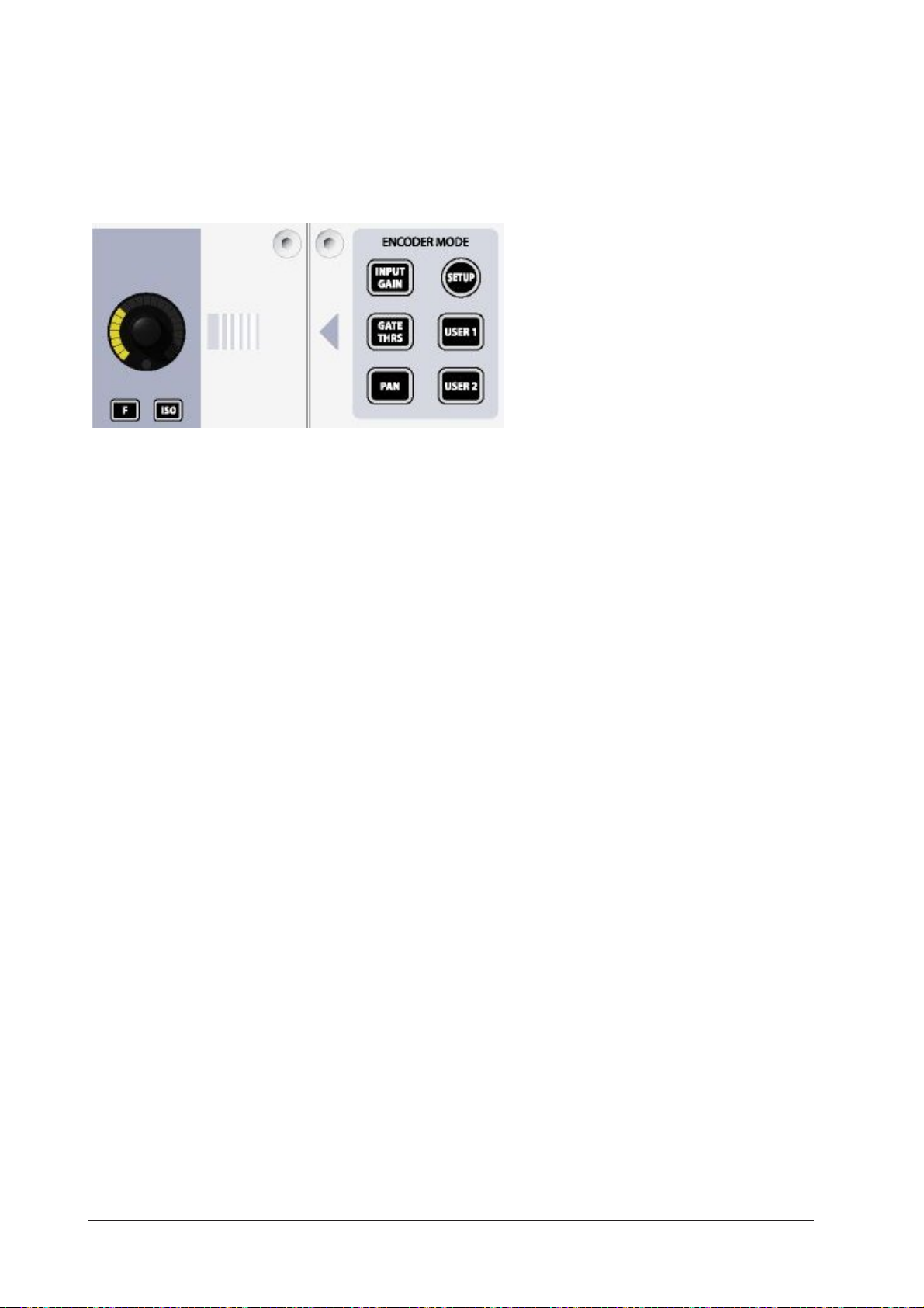
CHANNEL ENCODERS
Channel encoders always control a parameter on their own channel strip. The function of the channel
encoders can be globally selected via the [INPUT GAIN], [GATE THRS] and [PAN] keys on the Encoder
Mode panel (see Figure 7- 2).
Figure 7-2: Encoder Mode Panel.
[USER1] and [USER2] are currently used to set the channel encoders to control the Low-cut Filters and
the High-cut Filters respectively.
[SETUP] is reserved for future use.
HINT: If [ALL BUSSES] is active or a MATRIX output is soloed, the channel encoders are disabled and have
no function (the previous function is remembered however).
HINT: If Stereo Aux sends are assigned to the channel faders (using FLW Output Solo), the channel encoders control the PAN for their channel’s contribution to the soloed Stereo Aux bus.
Soundcraft Vi4™ User GuidePage 7 - 2
Page 87

CHANNEL VST ENCODER 1& 2
Figure 7-3: Default VST Encoders 1 & 2 For Input Bay.
VST Encoder Priority
If a higher priority assignment action occurs, VST encoder functions change immediately to this mapping.
The priority order of the possible assignment actions is:
Priority Function
highest CHANNEL EXPANDED FUNCTION (e.g.: EQ, Dynamics, etc)
FOLLOW OUTPUT SOLO
FAST ASSIGN
lowest USER or DEFAULT
HINT: If any touch field is activated, the 16 VST encoders are assigned with expanded channel function
parameters (see Chapter 4 for full details).
By default, the VST encoders 1 & 2 are assigned as AUX 1 and AUX 2 send level controls for their input
channels.
Soundcraft Vi4™ User Guide Page 7 - 3
Page 88

Figure 7-4: Vistonics Mode Panel
Changing Encoder Function
The function assigned to the VST encoders can be changed by the user via the Vistonics Mode panel (see
Figure 7-4).
The two [FAST ASSN] keys provide a very fast way to temporarily assign a bus function to a VST encoder
row. Press and hold one of the [FAST ASSN] keys, then press one of the Output Masters’ [SOLO/SEL] keys
( there will be no influence on audio, the Output solo is not activated). The relevant row of VST encoders
will now be assigned to that Output master, and the [FAST ASSN] key in question will illuminate.
Hint: Only Output Masters which are configured as Auxes use the encoders. Group Masters do, however,
use the VST button next to the encoder.
HINT: Fast assign mapping is removed by pressing/releasing [FAST ASSN]. Fast assign always works
GLOBALLY for all input strips
The [SETUP] key is reserved for future use.
If [USER] is pressed the two VST encoder rows will be assigned as AUX 3 and AUX 4 send level controls for
their input channels. The [USER] key is illuminated when active.
The two [FLW] keys activate the FOLLOW SOLO function for their respective encoder rows. This means that
pressing an Output Solo/sel will automatically assign the soloed Output to this row, overriding the default
or the [USER] layer. Note that only one [FLW] can be active at a time.
The [PAN] key, which is illuminated when it is active, only has an effect on Aux Masters which have been
configured as stereo pairs. If such a pair is assigned to a VST encoder row, and if the [PAN] key is active,
the encoders will control the pan between the pair rather than the contribution level.
HINT: If both Auxes assigned to Row 1 & 2 are Stereo Auxes, both Rows 1 and 2 will change to the PAN
function across the desk. If only one of the two rows is a Stereo Aux, then only this row will change to PAN.
If neither row has a Stereo Aux assigned, the [PAN] switch will have no function.
The [PRE/POST] key isn’t used for any encoder functions, but for the sake of completeness its function is
described here. The [PRE/POST] key allows the user to configure Aux sends from channels, when they are
assigned to the two VST encoder rows, as pre or post-fader.
Soundcraft Vi4™ User GuidePage 7 - 4
Page 89

MASTER BAY PANEL ENCODERS
The master bay has four panel-mounted encoders with LED rings (see Figure 7-1B): the TB/OSC Level
Control encoder, and the Sold Blend, Solo Trim & Phones Volume encoders. These are all dedicated to their
respective functions. A description of their functions is given in chapter 9 of this manual.
MASTER BAY VST ENCODERS
Figure 7-5: Default Master VST Encoder Assignment.
The default setting for the Master VST encoders is as the output level controls for Master Outputs 1-16.
This can also be selected by pressing the [PAGE A] key on the Master Vistonics Mode Panel (see Figure 7-
6). Pressing [PAGE B] will cause the Master VST encoders to be assigned as the output level controls for
Master Outputs 17-24.
The Master VST encoders can also be assigned to Master Output Expanded Functions (e.g. EQ, Dynamics,
etc.). When a Master Output [SOLO/SEL] key is touched, it opens the Processing Area in the Master VST
screen. If then a paticular touch-area is touched, the VST encoders are assigned to appropriate expanded
functions. These functions are all described in detail in chapter 5 of this manual.
HINT: [METER LOCK] must not be enabled, otherwise the Processing Area will not be displayed. If multiple
Output Solos are activated, the parameters for the LAST soloed Master are displayed.
Soundcraft Vi4™ User Guide Page 7 - 5
Page 90

Figure 7-6: Master VST Mode and Switch Function Panel.
Master Vistonics Switch Function Panel
Although the VST switches which are located next to the encoders are not the subject of this chapter, for
the sake of completeness a note on assigning their function is included here.
Using the three buttons on the Switch Function panel, the VST switches can be assigned to [TB ASSN],
[ON/OFF] or [SOLO/SEL]. [SOLO/SEL] is the default. The assigned function is the same for both Page A
and Page B.
These VST switch functions are, of course, over-ridden when the encoders are assigned to expanded
functions.
Soundcraft Vi4™ User GuidePage 7 - 6
Page 91

LAYERING (FADER PAGES)
GENERAL
Layers, or Fader Pages, allow the user to access different views of the DSP channel structure of the mixer,
on the control surface.
INPUTS
The Control Surface for the Soundcraft VI4™ contains four fully equipped Input Bays that allow direct
access and state information overview for 24 Input Channels.
Therefore two layers are required to allow operation for all 48 input channels.
Changing Layer is done by simply pressing the desired Input Fader Page key [A] or [B].
Figure 8-1: Desk In Layer A operation.
Soundcraft Vi4™ User Guide Page 8 - 1
Page 92
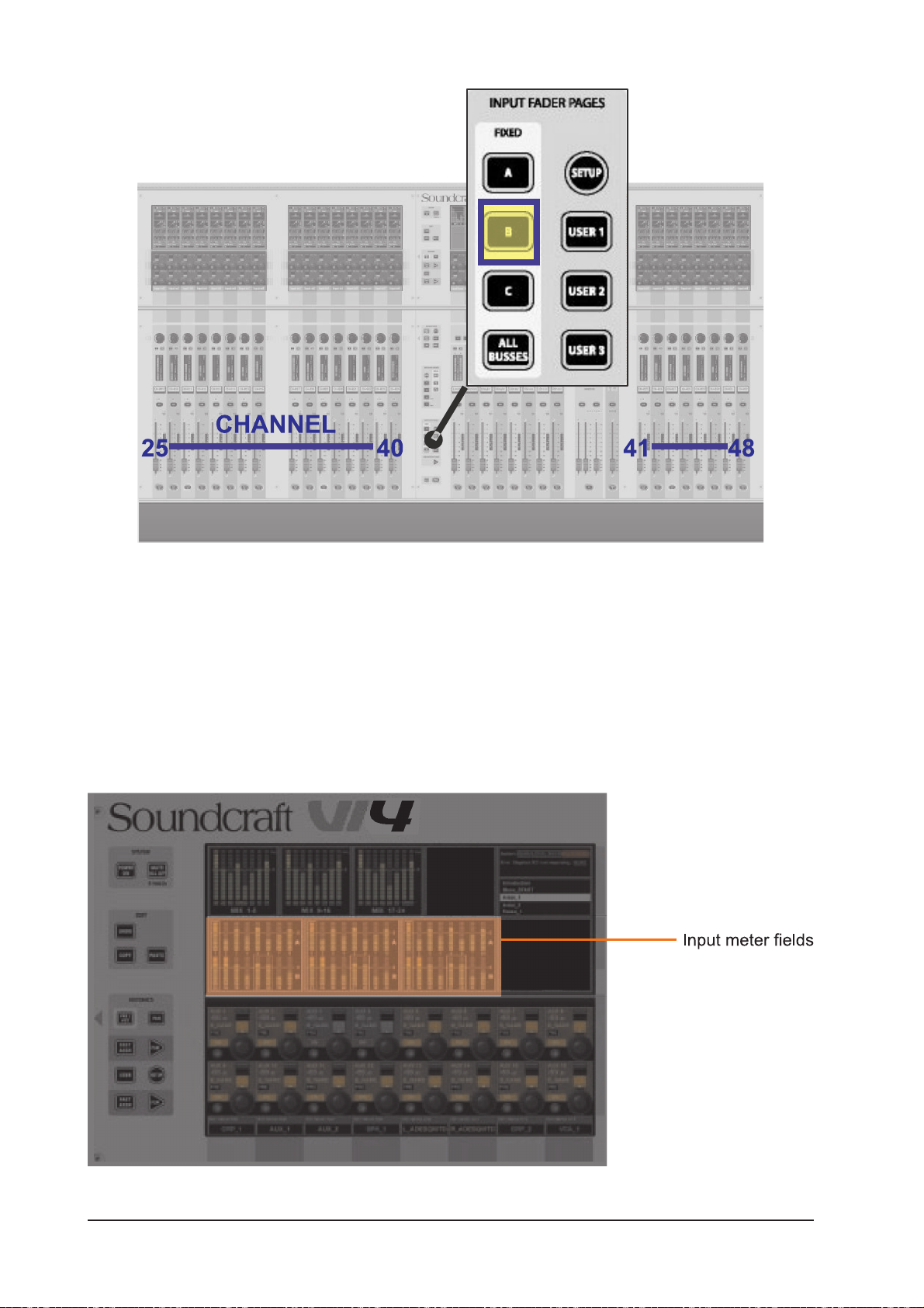
Figure 8-2: Desk In Layer B Operation.
Temporary Layer
Touching an input meter field on the Master Vistonics ™ Screen will temporarily display the 8 channels that
are in this group on input bay 3 of the surface.
The input fader page selector will blink to indicate that the bay 3 is temporarily remapped. Leaving the
mode can be done by pressing the input fader page selector or by touching the meter panel field again.
A highlighted box appears around the 8 selected meters when they have been touched.
Figure 8-3: Input Meter Fields.
Soundcraft Vi4™ User GuidePage 8 - 2
Page 93
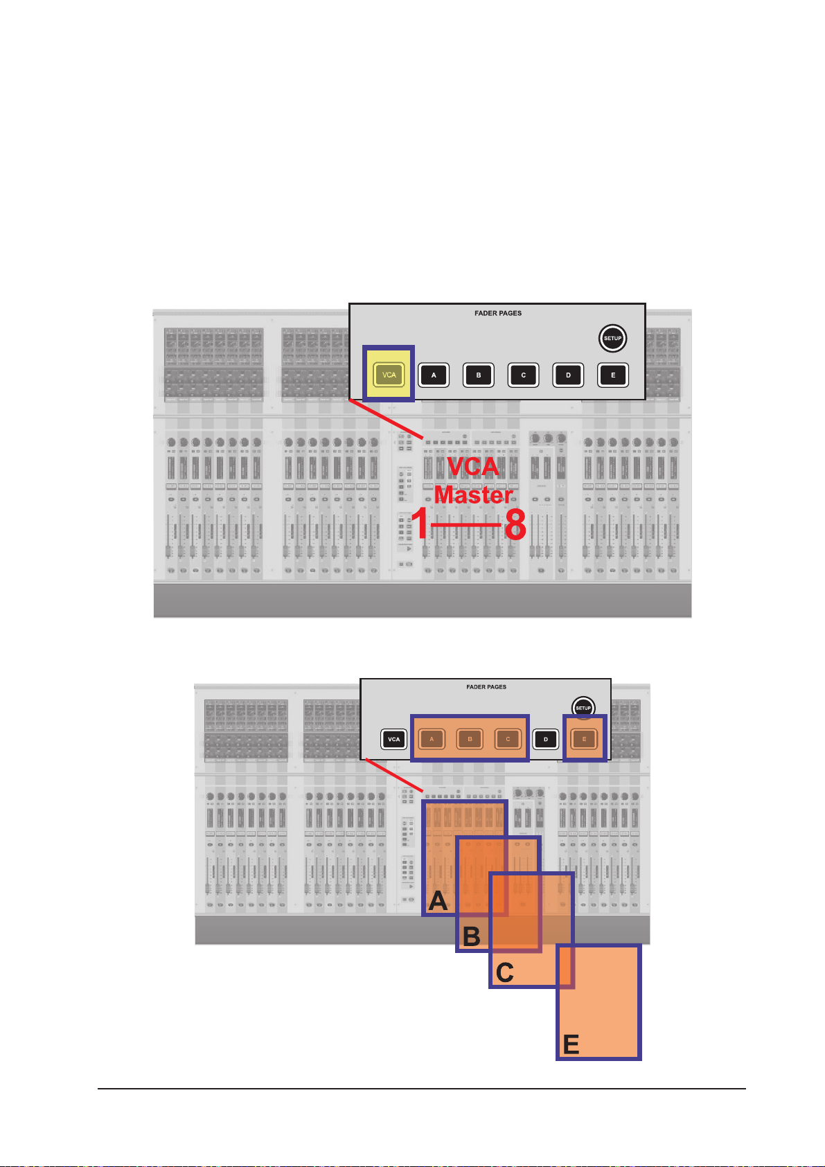
OUTPUTS
Bus Masters can be accessed with the master fader strips in the VST Master Area or with the ALL Bus layer
on the Input Bays.
Master Fader section
There are 5 layers for the master bay: VCA and A to E (not D). They map the following master faders to the
master bay as follows: VCA maps VCA 1-8, A maps busses 1-8, B maps busses 9-16, C maps busses 1724, D isn’t used, E maps VCA 9-16. In the factory-default Front-Of-House Show, busses 1-8 are set as Aux,
busses 9-16 are Groups, and busses 17-24 are set to Matrix.
Figure 8-4: Master Bay In VCA Operation.
Figure 8-5: Master Bay In Layer A-E Operation.
Soundcraft Vi4™ User Guide Page 8 - 3
Page 94

ALL Busses
If [ALL BUSSES] is selected in the Input Fader Pages, all 24 Busses will be assigned to the three Input
Fader Bays. This Layer allows a quick way to compare the outputs or quickly change the processing of the
Busses.
HINT: Configuration of the BUSSES, e.g. Format (mono/stereo) and Type (Aux, Grp, Matrix) is also handled
in this Layer.
Figure 8-6: ALL BUSSES Operation.
Soundcraft Vi4™ User GuidePage 8 - 4
Page 95

VST Master Area
The VST Master Area allows all 24 Bus Masters to be accessed even if the 8 output faders are assigned to
control VCA Masters.
There are two layers of encoders: Page A displays busses 1-8 and busses 9-16, Page B displays busses
17-24. In the factory-default Front-Of-House Show, busses 1-8 are set as Aux, busses 9-16 are Groups,
and busses 17-24 are set to Matrix.
Figure 8-7: VST Master Area.
Soundcraft Vi4™ User Guide Page 8 - 5
Page 96

Soundcraft Vi4™ User GuidePage 8 - 6
Page 97
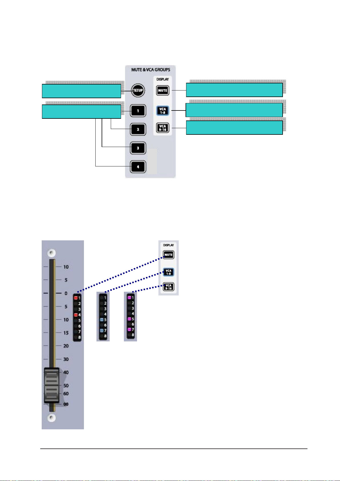
VCA & MUTE GROUPS
Soundcraft VI4™ supports up to 4 MUTE Groups (MG) and 16 VCA masters.
[SETUP]
MUTE Groups 1..4
Figure 9-1: MUTE & VCA Front Panel Keys
Display Mute Groups (red)
Display VCA 1..8 (blue)
Display VCA 9..16 (pink)
VCA/MUTE GROUP INDICATION
Each input and output strip contains a VCA/mute group display. [MUTE], [VCA 1-8] and [VCA 9-16] set the
display mode for all strips.
Figure 9-2. VCA/MUTE GROUP Indication
Soundcraft Vi4™ User Guide Page 9 - 1
Page 98

MUTE GROUP MASTER SWITCHES
The four switches labelled 1-4 activate Mute Groups when pressed.
VCA CONTROL GROUP BEHAVIOUR
Up to 16 VCA Groups can be created. In the normal configuration of the console with a single Output
section block, there are only 8 faders available for VCA Masters, therefore Output Fader pages must be
used to access all 16. Similarly there are only 8 assignment LEDs on the Channel and Output faders, and
these must be bank-switched with the display switches [VCA 1-8][VCA 9-16] in the Control Block, in order
to check all the assignments if more than 8 VCAs are being used.
AUDIO BEHAVIOUR
When a VCA Group has been created, by assigning Input or Output channels to a VCA Master, the following
behaviour is followed:
* The Master fader setting applies its dB value as an offset to all member channels. The member
channels’ fader positions remain unchanged.
* If a channel is assigned to more than one VCA Group, the resultant offset applied to the
channel is calculated as the arithmetic sum of the dB values of each VCA Master fader. Any
Master fader reaching –inf dB will set all member channels to –inf dB, regardless of other Master
fader settings. The maximum gain applied to a member channel as the result of the channel
fader setting plus offsets from VCA Master faders is limited to +10dB.
* The [ON]/Off switch on the VCA Master fader acts as a remote control for all member channels’
On/Off switches. If a channel which was previously ON is turned OFF by the action of a VCA
Master On/Off switch, the channel’s ON switch will illuminate in RED to distinguish this condition
from a manually OFF channel.
The VCA Master On/Off switch itself has only 2 states, and always illuminates RED when OFF,
Green when ON. (There is no non-illuminated condition). This is because VCA Master On/Offs
cannot themselves be remotely muted, so the Red helps to identify ‘Muted’ VCA masters.
* The [SOLO/SEL] switch on the VCA Master fader acts as a remote control for all member
channels’ Solo switches. The channel ‘Sel’ function is not activated however.
Soundcraft Vi4™ User GuidePage 9 - 2
Page 99

ASSIGNING VCAs
1. Press the VCA/MUTE GROUP’s [SETUP] key. It will glow blue.
2. Choose the required VCA master by pressing its [SOLO/SEL] key, which will also glow blue. Note that if
the output fader page is not displaying VCAs it will be necessary to select the [VCA] page (VCAs 1-8) or
the [E]page (VCAs 9-16) first.
3. Press the [SOLO/SEL] key of any channel(s) that is(are) to be assigned to the selected VCA master.
4. Press [SETUP] again to finish the process, or press another VCA master’s [SOLO/SEL] key to assign
more channels to another VCA master.
Hint: If the SETUP mode is not switched off after assigning VCAs, channels cannot be soloed.
Hint: The assignment of VCAs should be done with the channel or group faders and the VCA master, to
which assignment is being made, being at or near a nominal operating level: i.e. don’t assign a VCA master
to a channel or group if the VCA master is at -40dB while the channel or group is at 0dB.
ASSIGNING MUTE GROUPS
1. Press the VCA/MUTE GROUP’s [SETUP] key. It will glow blue.
2. Press the required mute group [1-4] master key, it will glow red. The MUTE/VCA display strip on each
channel will show mute assignments in red.
3. Press the [SOLO/SEL] key of any channel(s) that is(are) to be assigned to the selected MUTE master.
4. Press [SETUP] again to finish the process, or press another MUTE master’s key to assign more channels
to another MUTE master.
Hint: If the SETUP mode is not switched off after assigning MUTES, channels cannot be soloed.
ASSIGNING VCAS AND MUTE GROUPS TO OUTPUT CHANNELS
It is possible to assign VCAs and/or MUTE Groups to any of the 24 output channels (but not the LRC
master outputs). In step 3 of either of the assignment processes above, select one of the output fader
pages [A] to [C], and then use the [SOLO/SEL] key below the output fader to assign it to the VCA or Mute
Group in question. Note: you must not assign a VCA group to both input and output channels.
VCA GROUPS WHEN AUX SENDS ARE CONTROLLED BY CHANNEL FADERS
The VCA Groups on the Soundcraft Vi4™ are normally used to control groups of the input channel faders,
for use by FOH engineers. In this case they are used to group mono and/or stereo channels together under
control of a single master fader, for easier control during a mix. The member channels can also be Soloed
or Muted, using the VCA Master [SOLO/SEL] and [ON] switches.
For the Monitor mix engineer, controlling channel faders is of secondary importance to controlling Aux
sends from channels, and so on Soundcraft Vi4 the functionality of VCA Groups has been extended to
control of groups of Aux sends as well as channel faders.
Soundcraft Vi4™ User Guide Page 9 - 3
Page 100

Effectively, because there can be up to 24 mono Aux sends configured on the console, this means that
there are up to 24 sets of VCA groups (each with up to 16 Group Masters), in addition to the set of main
channel fader VCA groups. This means that there are up to 25 virtual sets of 16 VCA master faders in total.
VCA control of Auxes is only available by activating the Follow Output Solo [FLW] key next to the master
faders, note that the pair of [FLW] keys for the VST Encoder Rows will not access this function.
Due to the Follow Output Solo functionality, it is possible to control only one Aux mix via VCAs at any one
time.
Procedure
Select the Aux required by selecting the required master fader bank [A]-[C].
Activate the [FLW] key next to the master faders.
Press the [SOLO/SEL] key, under the master fader, for the required Aux. Alternatively, the Aux can be
soloed using the solo switches in the Master Vistonics™ screen.
Press [VCA] (for VCA 1-8) or [E](for VCA 9-16). The FaderGlow™ for the master faders will change to blue
(VCA 1-8) or pink (VCA 8-16). The faders will move to show the offsets which are being applied to the Aux
feeds from those channels which are assigned to the VCAs now being displayed in the master section. Note
that at this point the VCA Master [SOLO/SEL] keys have no function. The VCA [ON] switch controls the Aux
send On/Off on the member channels (the channel’s [ON] switch is illuminated red if the Aux send is
turned Off by a VCA Master [ON] switch.)
To select another Aux for adjustment, press the required bank key [A]-[C], solo the required aux (or solo
directly on the VST screen), and press [VCA] or [E]. To exit, press [SOLO CLEAR] and de-select [FLW].
In the example in Figure 9-3, input channel 1 has been assigned to VCA 1, and channels 2,3 & 4 have
been assigned to VCA 4. In order to use the VCAs to control the Aux 5 sends from the input channels
proceed as follows: select bank A, activate [FLW], solo Aux MASTER 5 using its [SOLO/SEL] key, press
[VCA]. VCA 4’s fader will now control the Aux 5 feeds from input channels 2, 3 & 4; and VCA 1’s fader will
now control the Aux 5 feed from input channel 1.
Figure 9-3. How VCA Groups Operate on Aux Sends.
Soundcraft Vi4™ User GuidePage 9 - 4
 Loading...