

Page 1
User Guide v1.4
®
Page 2
Vi3000 USER MANUAL
®
IMPORTANT INFORMATION
IMPORTANT
Please read this manual carefully before using your mixer for the
rst time.
This equipment complies with the EMC directive 2004/108/EC
and LVD 2006/95/EC
This product is approved to safety standards
IEC 60065:2001 (Seventh Edition) +A2:2010
EN60065:2002 +A1:2006 +A2:2010 +A11:2008 +A12:2011
UL60065 2012 7th Edition
CAN/CSA-E60065-03 + A2: 2012
And EMC standards
EN55103-1: 2009
EN55103-2: 2009
Warning: Any modication or changes made to this device, unless explicitly approved by
Harman, will invalidate the authorisation of this device. Operation of an unauthorised
device is prohibited under Section 302 of the Communications act of 1934, as amended,
and Subpart 1 of Part 2 of Chapter 47 of the Code of Federal Regulations.
NOTE: This equipment has been tested and found to comply with the limits for a Class B digital device, pursuant to
Part 15 of the FCC Rules. These limits are designed to provide reasonable protection against harmful interference in
a residential installation. This equipment generates, uses and can radiate radio frequency energy and, if not installed
and used in accordance with the instructions, may cause harmful interference to radio communications. However,
there is no guarantee that interference will not occur in a particular installation. If this equipment does cause harmful
interference to radio or television reception, which can be determined by turning the equipment off and on, the user is
encouraged to try to correct the interference by one or more of the following measures:
* Reorient or relocate the receiving antenna
* Increase the separation between the equipment and the receiver
* Connect the equipment into an outlet on a circuit different from that to which the receiver is connected.
* Consult the dealer or an experienced radio/TV technician for help
© Harman International Industries Ltd. 2014 All rights reserved
Parts of the design of this product may be protected by worldwide patents.
Part No. 5042292
Rev 1.0
E&OE September 2014
Soundcraft is a trading division of Harman International Industries Ltd. Information in this manual is subject to change
without notice and does not represent a commitment on the part of the vendor. Soundcraft shall not be liable for any
loss or damage whatsoever arising from the use of information or any error contained in this manual. No part of this
manual may be reproduced, stored in a retrieval system, or transmitted, in any form or by any means, electronic,
electrical, mechanical, optical, chemical, including photocopying and recording, for any purpose without the express
written permission of Soundcraft.
Harman International Industries Limited
Cranborne House, Cranborne Road, Potters Bar, Hertfordshire, EN6 3JN, UK
Tel: +44 (0)1707 665000
Fax: +44 (0)1707 660742
http://www.soundcraft.com
IMPORTANT INFORMATION
Page 3

Vi3000 USER MANUAL: CONTENTS
®
1.0 INTRODUCTION
1.1: Saftey Notices & Warnings
1.2: Product Warranty
2.0: SPECIFICATIONS
2.1: Console block diagram
3.0: QUICK START GUIDE
4.0: HARDWARE OVERVIEW
4.1: Local I/O
4.2: MADI / DANTE Sources / Switching
5.0 OPERATIONS OVERVIEW
5.1: Manual Conventions
5.2: Vistonics II
5.3: Console Bays
5.4: FaderGlow™
5.5: Buttons
5.6: Encoders
5.7: Gangs
5.8: Labelling
6.0: INPUTS
6.1: Navigation - Fader Pages
6.2: The Channel Strip
6.3: Encoder Mode
6.4: VST Control
6.5: Touchscreen / Signal Path
6.5.1: Input Section
6.5.2: EQ
6.5.3: Dynamics
6.5.4: Busses
6.5.5: Output Section
7.0: OUTPUTS
7.1: LCR Mix Masters
7.2:BusConguration
7.3: Bus Master Control
7.3.1: Master Vistonics Control
7.3.2: Channel Strip
7.3.3: Processing Chain
7.3.4: Graphic EQs
8.0: MATRIX SYSTEM
9.0: MUTE & VCA GROUPS
9.1: Mute Groups
9.2: VCA Groups
9.3: Aux VCA Groups
10.0: MONITORING
10.1: Console Controls
10.2: Setup
10.2.1: MON Setup
11.0: SOLO SYSTEM
11.1: Primary Behaviour
11.2: Input Priority Mode
11.3: Autocancel Behaviour
11.4: Follow Output Solo Mode
12.0: METERING
12.1: Inputs
12.2: Busses
13.0: EDIT SYSTEM
(COPY, PASTE, AND LIBRARY)
13.1: Copy, Paste, Undo
13.2: Library Basics
13.3: Library File Screen
14.0: SNAPSHOTS, CUELISTS, GLOBAL FILTER
14.1: Console Controls
14.2: Cuelist Control
14.3: Cue Details
14.3.1: Cue Number & Timecode
14.3.2: Snapshot/Cue Name
14.3.3: MIDI
14.3.4: GPIO
14.4: Snapshot Filters
14.4.1: Snapshot Filter Scope
14.4.2: Global Filter
15.0: TALKBACK & OSCILLATOR
15.1: Console Controls
15.2: Oscillator Setup & Use
15.3: Talkback Setup
15.4: Talkback Return Setup
16.0: MAIN MENU
16.1: Main (Screen, Security)
16.2: Shows
16.2.1: Show File Data
16.3: GPIO
16.4: Sync
16.5: Tielines
16.6: FX
16.7: MIDI
16.8: Log
16.9: Settings
16.10: System
17.0: LEXICON FX
17.1: Using The FX Processors
17.1.1: Tap Tempo Functionality
17.2: FX Algorithms & Parameters
17.2.1: Reverbs
17.2.1: Delays
17.2.1: Misc
18.0: VM² WIreless Status Monitoring / HiQnet
18.1:HiQnetNetworkConguration
18.1.1: VM ² Device List
18.2: Status Displays
18.2.1: Channel Strip Status
18.2.2: VST Status
CONTENTS
Page 4
Vi3000 USER MANUAL
®
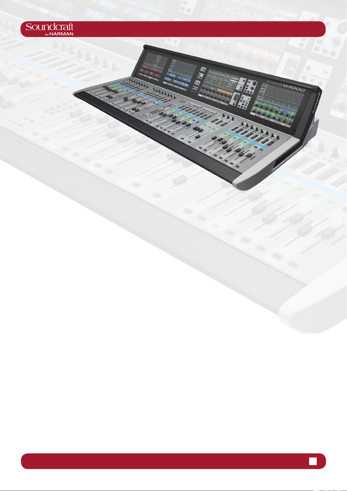
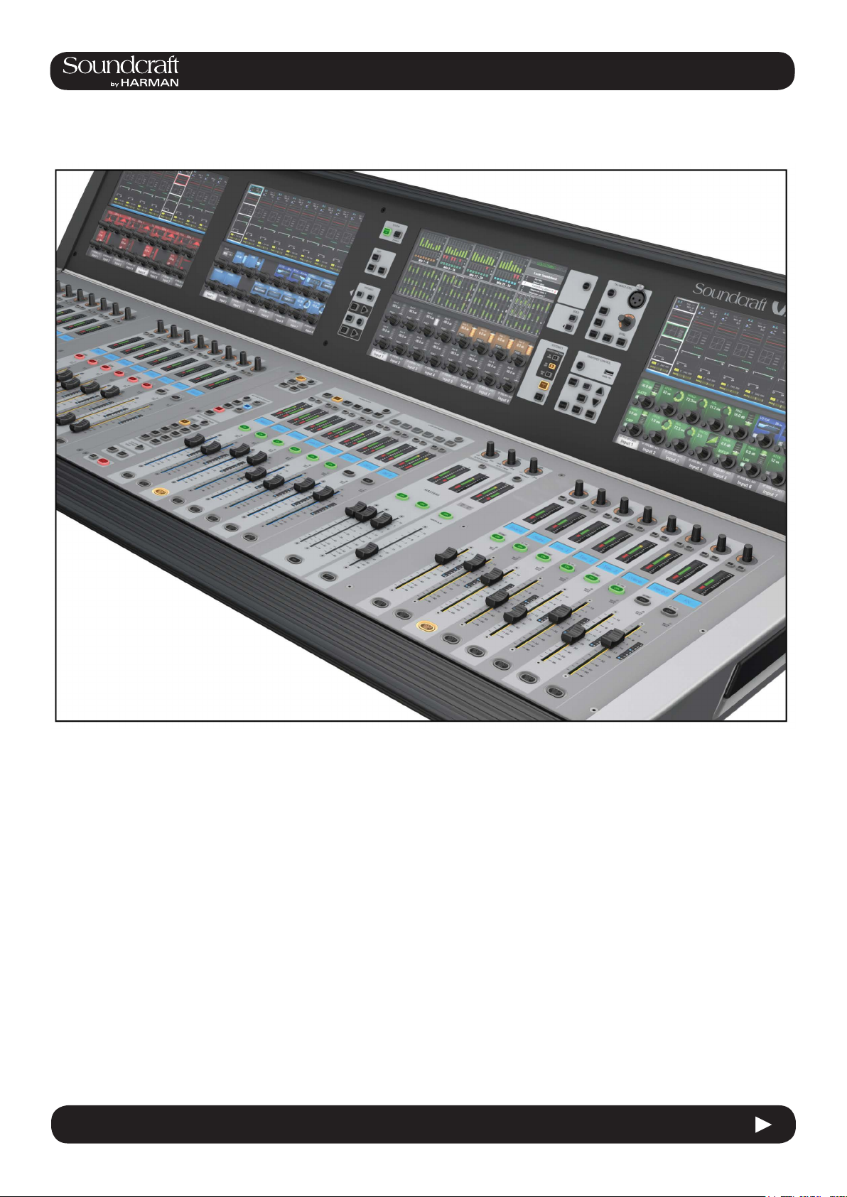
Welcome To The Vi3000!
New Look
The Soundcraft Vi3000 features an all-new appearance
with a more efciently designed control surface, 36
faders, 24 mono/stereo busses and a sweeping black
screen panel with four Vistonics II™ touchscreen interfac-
es with sleek, updated 3D graphics. Because the Vi3000
has four touchscreens, it’s the only console in its class
that can be used by two engineers at the same time. And
at show time... Settings libraries, copy/paste functions,
sophisticated automation and radio mic status monitoring,
FaderGlow™, processing from dbx, BSS, Lexicon and
Universal Audio (Optional Realtime Rack), and more will
not let you down.
SpiderCore DSP
The Vi3000 is a console with friends in high places.
Sound quality is assured by Soundcraft SpiderCore - a
brand new 40-bit oating point DSP engine that mixes
FPGA and DSP technology in a unique combination
that maximises I/O routing and DSP mixing capability
in a footprint small enough for inclusion within a control
surface.
FX
Internal FX come courtesy of 4 independent stereo
Lexicon multi effects units, each providing a choice of 14
reverbs, 7 delays and 8 pitch shifting effects, patchable
to input channels, aux outputs and channel inserts. BSS
third-octave Graphic EQ is available on every bus output,
with fader bays illuminating in red to indicate GEQ mode.
...And More FX
The Vi3000 can also accommodate the new Soundcraft
Realtime Rack, a hardware/software unit designed in collaboration with plug-in manufacturer Universal Audio that
provides access to 74 industry-standard UAD plug-ins.
1.0: Introduction
DANTE As Standard
The Vi3000 is the rst Soundcraft console to incorporate
a Dante interface as standard, for seamless digital audio
networking with Dante-enabled devices.
Connectivity
In addition to a full complement of analog and digital inputs and outputs, the console provides MIDI, USB, Ethernet, DVI out, Dante/MADI record feed outputs, redundant
power supply and other connections. The Vi3000 has two
expansion bays that can be tted with MADI Stagebox
cards, to connect multiple Soundcraft Stagebox input
expander modules.
Shine A Light
Along with its greatly expanded functionality, the Vi3000
retains all the features that have made the Soundcraft Vi
Series the consoles of choice for live sound engineers
worldwide, such as FaderGlow™ - illuminated faders that
display different colors according to function, the ability
to store and recall snapshots and cues, compatibility with
Soundcraft’s ViSi app that allows remote control from an
iPad.
Optional 64 channel stagebox
With up to 48 on-board mic inputs, Vi3000 is happy to
work with existing analogue multicore systems. Also
available is an optional remote stagebox housing 64
analogue mic/line inputs and 32 analogue line outputs,
with 48V phantom power and a 80Hz HPF before the A-D
converters. Mic amp gain can be controlled remotely from
the console surface.
1.0 1.0 Introduction
Page 5
4.3: INPUT CHANNEL > DYNAMICS
®
®
Vi3000 USER MANUAL
Vi3000 USER MANUAL
1.1: INTRODUCTION > SAFETY
SAFTEY NOTICES
For your own safety and to avoid invalidation of the warranty
please read this section carefully.
THIS UNIT MUST BE EARTHED
Under no circumstances should the mains earth be disconnected from the mains lead.
The wires in the mains lead are coloured in accordance with the following code:
Earth: Green and Yellow (Green/Yellow - US)
Neutral: Blue (White - US)
Live: Brown (Black - US)
As the colours of the wires in the mains lead may not correspond with the coloured markings identifying
the terminals in your plug, proceed as follows:
The wire which is coloured Green and Yellow must be connected to the terminal in the plug which is
marked with the letter E or by the earth symbol.
The wire which is coloured Blue must be connected to the terminal in the plug which is marked with
the letter N.
The wire which is coloured Brown must be connected to the terminal in the plug which is marked
with the letter L.
Ensure that these colour codings are followed carefully in the event of the plug being changed.
The internal power supply unit contains no user serviceable parts. Refer all servicing to a
qualied service engineer, through the appropriate Soundcraft dealer.
4.3 INPUT CHANNEL > De Esser
1.1 1.1: INTRODUCTION > SAFETY
Page 6

Vi3000 USER MANUAL
®
1.1: INTRODUCTION > SAFETY
WARNINGS
• Read these instructions.
• Keep these instructions.
• Heed all warnings.
• Follow all instructions.
• Clean the apparatus only with a dry cloth.
• Do not install near any heat sources such as radiators, heat resistors, stoves, or other apparatus
(including ampliers) that produce heat.
• Do not block any ventilation openings. Install in accordance with the manufacturer’s instructions.
• Do not use this apparatus near water.
• Do not defeat the safety purpose of the polarized or grounding type plug. A polarized plug has two
blades with one wider than the other. A grounding type plug has two blades and a third grounding
prong. The wide blade or the third prong are provided for your safety. When the provided plug does not
t into your outlet, consult an electrician for replacement of the obsolete outlet.
• Protect the power cord from being walked on or pinched particularly at plugs, convenience recectacles and the point where they exit from the apparatus.
• Only use attachments/accessories specied by the manufacturer.
• Unplug this apparatus during lightning storms or when unused for long periods of time.
• Refer all servicing to qualied service personnel. Servicing is required when the apparatus has been
damaged in any way such as power-supply cord or plug is damaged, liquid has been
spilled or objects have fallen into the apparatus, the apparatus has been exposed to rain or
moisture, does not operate normally or has been dropped.
• Use only with the cart, stand, tripod, bracket or table specied by the manufacturer, or sold
with the apparatus. When the cart is used, use caution when moving the cart/apparatus combination to
avoid injury from tip-over.
• No naked ame sources, such as lighted candles or cigarettes etc., should be placed on the
apparatus.
• Warning: To reduce the risk of re or electric shock, do not expose this apparatus to rain or moisture.
Do not expose the apparatus to dripping or splashing and do not place objects lled with liquids, such
as vases, on the apparatus.
• No user serviceable parts. Refer all servicing to a qualied service engineer, through the appropriate Soundcraft dealer.
• Ventilation should not be impeded by covering the ventilation openings with items such as
newspapers, table cloths, curtains etc.
• It is recommended that all maintenance and service on the product should be carried out by Soundcraft or its authorised agents. Soundcraft cannot accept any liability whatsoever for any loss or damage
caused by service, maintenance or repair by unauthorised personnel.
1.1 1.1: INTRODUCTION > SAFETY
Page 7

4.3: INPUT CHANNEL > DYNAMICS
®
®
Vi3000 USER MANUAL
Vi3000 USER MANUAL
1.2: INTRODUCTION > WARRANTY
WARRANTY
1 Soundcraft is a trading division of Harman International Industries Ltd.
End User means the person who rst puts the equipment into regular operation.
Dealer means the person other than Soundcraft (if any) from whom the End User purchased the Equipment, pro-
vided such a person is authorised for this purpose by Soundcraft or its accredited Distributor.
Equipment means the equipment supplied with this manual.
2 If within the period of twelve months from the date of delivery of the Equipment to the End User it shall prove
defective by reason only of faulty materials and/or workmanship to such an extent that the effectiveness and/or
usability thereof is materially affected the Equipment or the defective component should be returned to the Dealer
or to Soundcraft and subject to the following conditions the Dealer or Soundcraft will repair or replace the defec-
tive components. Any components replaced will become the property of Soundcraft.
3 Any Equipment or component returned will be at the risk of the End User whilst in transit (both to and from the
Dealer or Soundcraft) and postage must be prepaid.
4 This warranty shall only be available if:
a) The Equipment has been properly installed in accordance with instructions contained in Soundcraft’s manual.
b) The End User has notied Soundcraft or the Dealer within 14 days of the defect appearing; and
c) No persons other than authorised representatives of Soundcraft or the Dealer have effected any replacement
of parts maintenance adjustments or repairs to the Equipment; and
d) The End User has used the Equipment only for such purposes as Soundcraft recommends, with only such
operating supplies as meet Soundcraft’s specications and otherwise in all respects in accordance Soundcraft’s
recommendations.
5 Defects arising as a result of the following are not covered by this Warranty: faulty or negligent handling, chem-
ical or electro-chemical or electrical inuences, accidental damage, Acts of God, neglect, deciency in electrical
power, airconditioning or humidity control.
6. The benet of this Warranty may not be assigned by the End User.
7. End Users who are consumers should note their rights under this Warranty are in addition to and do not affect
any other rights to which they may be entitled against the seller of the Equipment.
4.3 INPUT CHANNEL > De Esser
1.2 1.2: INTRODUCTION > WARRANTY
Page 8

Vi3000 USER MANUAL
®
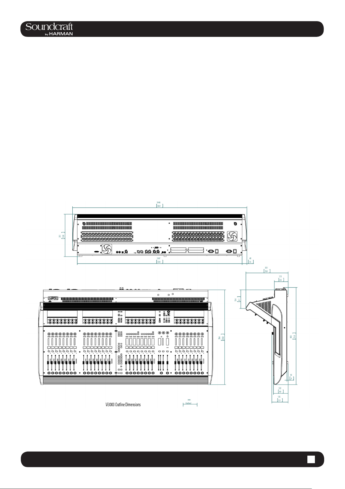
2.0:Vi3000Specications
Vi3000 Specications
Frequency Response
StageboxorLocalMicinputtoLineoutput +0/-1dB, 20Hz-20kHz
AES/EBUIntoAES/EBUOut +0/-0.2dB, 20Hz-20kHz
T.H.D. & Noise
(22Hz-22kHz, unweighted)
StageboxorLocalMicIn(mingain)toLocalLineOut <0.004% @ 1kHz
StageboxMicIn(maxgain)toLocalLineOut <0.035% @ 1kHz
Mic Input E.I.N. <-127dBu (150Ω source)
(22Hz-22kHz bandwidth, unweighted)
Residual Noise -95dBu
(Stagebox line output; no inputs routed, Mix fader @0dB)
CMRR 80dB @ 1kHz
(Stagebox Mic input)
Sampling Frequency 48kHz
Latency < 2ms @48kHz
(Stagebox Mic Input to Local Line output)
AES/EBU Input Sample Rate 32–108kHz (with SRC enabled)
DSP Resolution 40-bit oating point
Internal Clock
Accuracy < +/- 50ppm
Jitter < +/- 2ns
2.0 2.0:Vi3000Specications
Page 9

Vi3000 USER MANUAL
®
®
Vi3000 USER MANUAL
External Sync BNC Wordclock, Dante network clock
Input & Output Levels
Mic/lineInputs +28dBu max
LineOutputs +22dBu max
NominalOperatingLevel +4dBu (-18dBFS)
Input & Output Impedances
MicInputs 2k7Ω
AllotheranalogueInputs >10kΩ
LineOutputs <75Ω
4.3: INPUT CHANNEL > DYNAMICS
2.0:Vi3000Specications
AES/EBUOutputs 110Ω
Oscillator 20Hz to 20kHz/Pink/White Noise, variable level
Channel Filters
MicInHPFilter 80Hz xed, 12dB per octave
ChannelHPFilter 20Hz-600Hz, 18dB per octave
ChannelLPFilter 1kHz-20kHz, 18dB per octave
EQ (Inputs and Bus Outputs)
HF 20Hz-20kHz, +/-18dB, Q= 0.3-8.7 or shelving
Hi-Mid 20Hz-20kHz, +/-18dB, Q=0.3-8.7
Lo-Mid 20Hz-20kHz, +/-18dB, Q=0.3-8.7
LF 20Hz-20kHz, +/-18dB, Q= 0.3-8.7 or shelving
Metering Internal 20-segment LED bargraphs plus 9-segment gain reduction meters for all inputs and
Outputs Peak hold variable from 0-2s.
Mains Voltage Operating Range 90-264V, 47-63Hz, auto-ranging
4.3 INPUT CHANNEL > De Esser
2.0 2.0:Vi3000Specications
Page 10
Vi3000 USER MANUAL
®
2.0:Vi3000Specications
Mains Power Consumption
Console 300W (both PSUs operating)
Stagebox(64in/32out) 150W (both PSUs operating)
Internal Mass Storage 120GB SSD Hard Drive
Temperature/Humidity Range
OperatingTemperatureRange 0°C – 45°C (32°F – 113°F)
RelativeHumidity 0% – 90%, non-condensing Ta=40°C (104°F)
StorageTemperatureRange -20°C – 60°C (-4°F – 140°F)
Weight 54kg
Soundcraftreservestherighttoimproveorotherwisealteranyinformationsuppliedinthis
documentoranyotherdocumentationsuppliedhereafter.E&OE05/2014
2.0 2.0:Vi3000Specications
Page 11
4.3: INPUT CHANNEL > DYNAMICS
®
®
INPUTS
WCLK
Dante
D21m compatible expansion
Up to 3 cards with 16
D21m compatible expansion
Vi3000 USER MANUAL
Vi3000 USER MANUAL
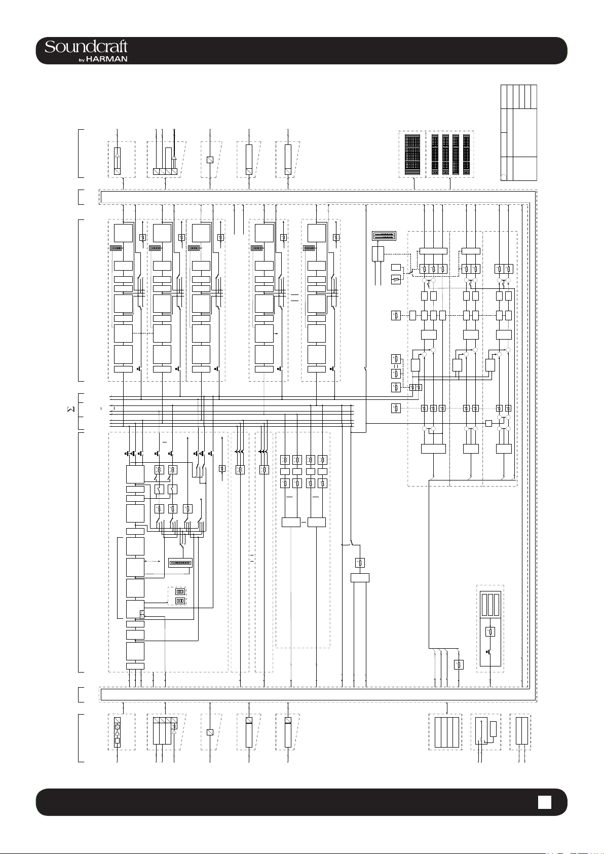
2.1:Vi3000BlockDiagram
a
OUTPUTS
MIX/MTX SOLO
MASTER
A
LINE OUT LOCAL I/O
D
MASTER L
GRM
LEVEL
LOW-
I
N
ON
FADER DELAY
I
N
Limiter
DYNAMIC
EQUALIZER
I
N
MASTER LEFT
SOLO R
SOLO L
MIX or MTX 24
MIX or MTX 2
MIX or MTX 1
MASTER C
MASTER R
MASTER L
d
d
a
P
H
B
T
p
B
USB
S
U
S
E
A
Channels per card
Up to 3 cards with 16
to MTX
INS SEND
TRIM
CUT
S
PF
AF
AON
PF
AON
S
ST
LINK
Compressor
4 band
S
SOLO
MASTER L
MASTER R
MASTER C
A
D
D
D
D
D
D
D
8
to MTX
MASTER R
TRIM
GRM
LEVEL
CUT
LOW-
I
S
N
PF
ON
PF
FADER DELAY
I
S
N
Limiter
DYNAMIC
Compressor
4 band
EQUALIZER
I
S
N
MASTER RIGHT
SOLO
MIX 24
MIX 1
d
64
D
D
Dante and MADI (OUT)
64
to MTX
MASTER C
INS SEND
AF
AON
AON
DIR OUT
TRIM
GRM
LEVEL
CUT
LOW-
I
S
N
PF
AF
ON
PF
FADER DELAY
I
S
N
Limiter
DYNAMIC
Compressor
4 band
EQUALIZER
I
S
N
SOLO
MASTER CENTRE
SOLO L
SOLO R
P SOLO
x
64
X
slot
X
D
D21m compatible expansion
64
24
INS SEND
INS SEND
DIR OUT 96
GRM
AON
AON
MIX or MTX 1
INS SEND
MASTER L
MASTER R
MASTER C
x
64
X
slot
X
D
D21m compatible expansion
64
to MTX
MIX BUS 1
INS SEND
TRIM
LEVEL
CUT
LOW-
I
S
N
PF
AF
AON
ON
PF
AON
FADER DELAY
I
S
N
ST
LINK
Limiter
DYNAMIC
Compressor
4 band
EQUALIZER
I
S
N
SOLO
to MTX
MIX BUS 24
TRIM
GRM
LEVEL
CUT
LOW-
I
S
N
PF
AF
ON
PF
FADER DELAY
I
S
N
Limiter
DYNAMIC
Compressor
4 band
EQUALIZER
I
S
N
MIX or MTX 24
SOLO
TB to EXT
INS SEND
A or B
ENAB A/B
MON FADER
SOLO pre TRIM
AON
AON
Source pre BLE ND
MON Delay
TB EXT
BUS 1 BUS 24IN
SOLO TRIM
BLEND
9..16 17..24
GUI IN Meter
GUI OUT Meter
1..8
MON_A LEFT
ON
+
MNTR B
TB
DIM
0..2000 mS
Logic
Delay
LR/
RR/
[+/-10 dB]
+
SOLO
Enable
IN/OUT
+
[-inf..-10 dB]
MASTER L
MASTER R
MASTER C
Left
65..72
(Based on Vi 6 Audio Block Diagram V0.748)
Vi 3000
9..16
33..40 41..48
1..8 17..24
MON_A RIGHT
MON_A CENTER
ON
+
TB
DIM
Delay
LL
+
+
Right
Center
A
SEL
73..80 81..88 89..96
25..32
49..57 58..64
MON_B LEFT
+
TB
Delay
Delay
+
SOLO
Enable
IN/OUT
+
Left
PHONES LEFT
MON_B RIGHT
ON
+
+
TB
TB
DIM
DIM
Delay
Delay
LL
LR/
RR/
+
+
SOLO
Enable
IN/OUT
+
sidetone
-15
+
+
Left
Center
Right
B
SEL
Audio Block Diagram
Regensdorf
Switzerland
1.0 19.05.14MUS
TIE LINE 24
PHONES RIGHT
+
TB
DIM
DIM
Delay
LL
LR/
RR/
+
+
+
Right
Center
SEL
HP
AFL
PFL
Bundle
Follow/
I
S
N
ON
FADER PAN
AF
PF
PP
PE
AF
I
S
N
PF
DELAY
LINK (ST)
Limiter
DYNAMIC
Compressor
INPUT CHANNELS / MATRIX MASTER / MIX / MONITORING
PROCESSING
PATCH PATCH
O
/
I
A
L
A
C
O
L
E
N
I
L
/
C
PAD
I
M
a
DYN
EQUALIZER
4 band param
GATE/Dees
I
S
N
&
HI
CUT
LOW
TRIM
PHASE
SEL
OSC
INP 1
INP 2
INS RET
16 16
D
P
H
B
T
B
S
U
S
E
A
Channels per card
PF
PP
AF
PE
LEVEL
of same
Bay A/B
to CH Dyn
Dees
GUI
GATE
KEY
8
D
D
D
D
D
D
D
D
SFC
SFC
USB
d
d
a
TRIM
To MTX
PP
GRM
SC/ES
SOLO
MONO INPUT
64
D
D
Dante or MADI (IN)
64
d
BUS FEED 1
CHANNEL 1 to 96
MIX BUS 1
64
D
X
slot
X
64
x
ON
ON
ON
ON
MTX 1
MTX 24
MTX 1
MTX 24
1
SEL
SEL
MTX
MTX
TB to BUS / MTX / EXT
24
OSC to TB
TB
OSC
TB SEND
TB
SEL
MON_A_Source
3
MONITOR_A
MATRIX
3
BUS FEED 24
24
24
MTX 1_SRC
MTX 16_SRC
OSC
TB_SRC
MIX BUS 24
TB_MIC
3
MON_A_Source
MON_B_Source
#
64
D
X
slot
X
64
x
FX
LEX 1
MON_B_Source
3
MONITOR_B
3
TB RET
MON_HP_Source
TB from ext
LEX 2
LEX 3
LEX 4
MON_HP_Source
TB from ext
3
MONITOR_HP
SINUS
PINK NOISE
WHITE NOISE
OSCILLATOR
TIE LINE
OSC
CLOCK
24
48k
IN
OUT
MIDI
4.3 INPUT CHANNEL > De Esser
2.1 2.1:Vi3000BlockDiagram
Page 12
Vi3000 USER MANUAL
®
3.0 QUICK START
Quick Start Guide
This chapter is a pictorial guide through the main concepts and functionality of the Vi3000 console.
Subsequent chapers go into these functions in more detail.
Console Sections
Vistonics II
3.0 - 1 3.0 QUICK START
Page 13
4.3: INPUT CHANNEL > DYNAMICS
®
®
Vi3000 USER MANUAL
Vi3000 USER MANUAL
3.0 QUICK START
Buttons And Encoders
Ganging
4.3 INPUT CHANNEL > De Esser
3.0 - 2 3.0 QUICK START
Page 14
Vi3000 USER MANUAL
®
3.0 QUICK START
Inputs & Controls
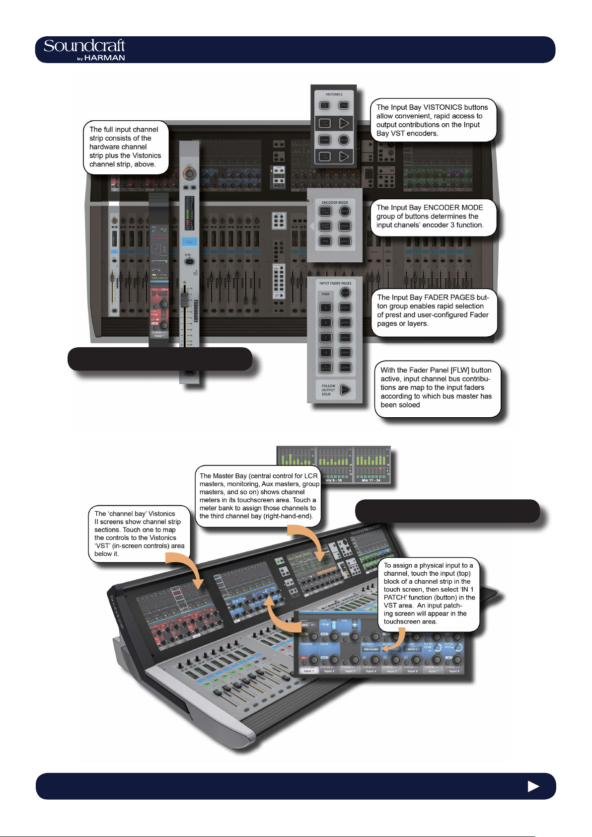
Input Channel Access
3.0 - 3 3.0 QUICK START
Page 15
4.3: INPUT CHANNEL > DYNAMICS
®
®
Vi3000 USER MANUAL
Vi3000 USER MANUAL
3.0 QUICK START
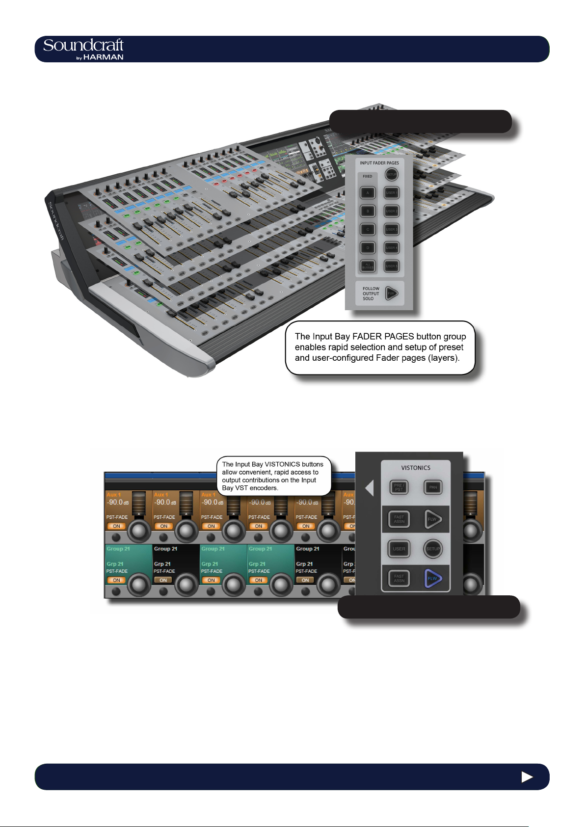
Fader Pages
Output Assignment
4.3 INPUT CHANNEL > De Esser
3.0 - 4 3.0 QUICK START
Page 16
Vi3000 USER MANUAL
®
3.0 QUICK START
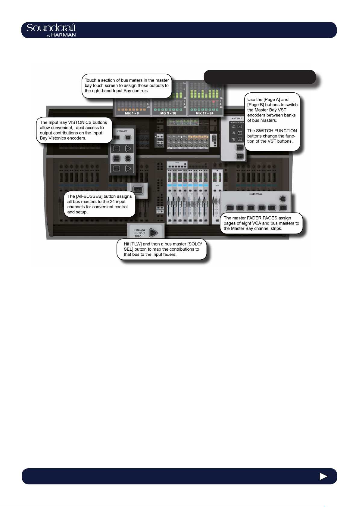
Outputs & Control
3.0 - 5 3.0 QUICK START
Page 17
®
®
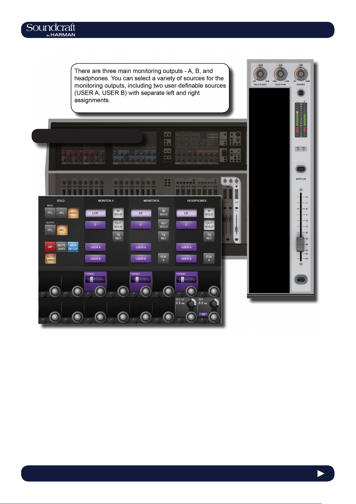
Monitoring
4.3: INPUT CHANNEL > DYNAMICS
Vi3000 USER MANUAL
Vi3000 USER MANUAL
3.0 QUICK START
4.3 INPUT CHANNEL > De Esser
3.0 - 6 3.0 QUICK START
Page 18
Vi3000 USER MANUAL
®
3.0 QUICK START
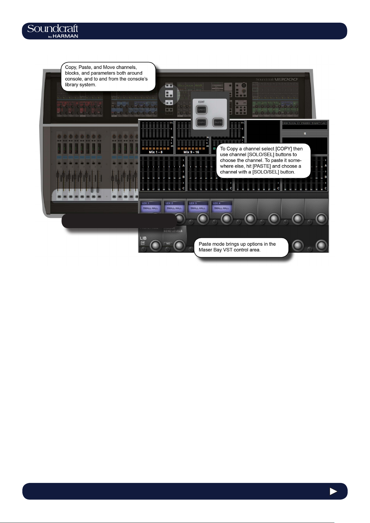
Copy, Paste, Move, LIbrary
3.0 - 7 3.0 QUICK START
Page 19
4.3: INPUT CHANNEL > DYNAMICS
®
®
Vi3000 USER MANUAL
Vi3000 USER MANUAL
3.0 QUICK START
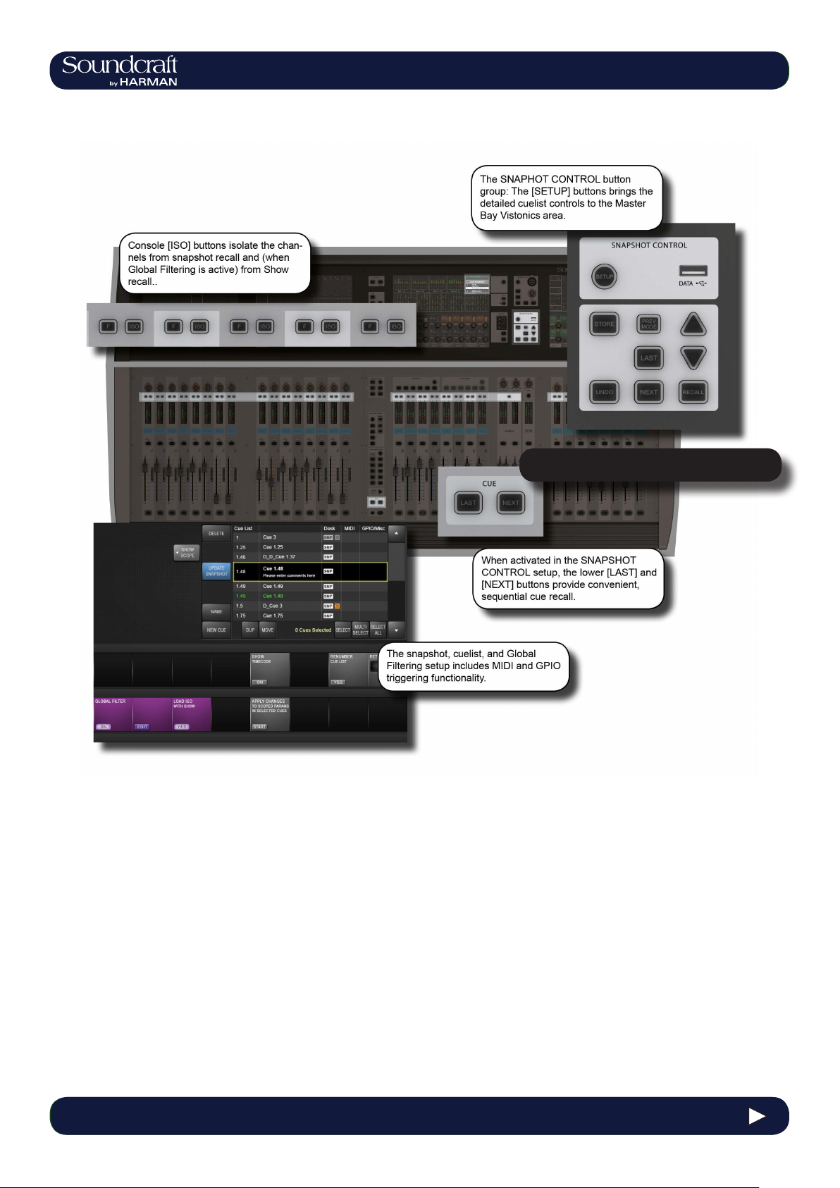
Snapshot & Cuelist
4.3 INPUT CHANNEL > De Esser
3.0 - 8 3.0 QUICK START
Page 20
®
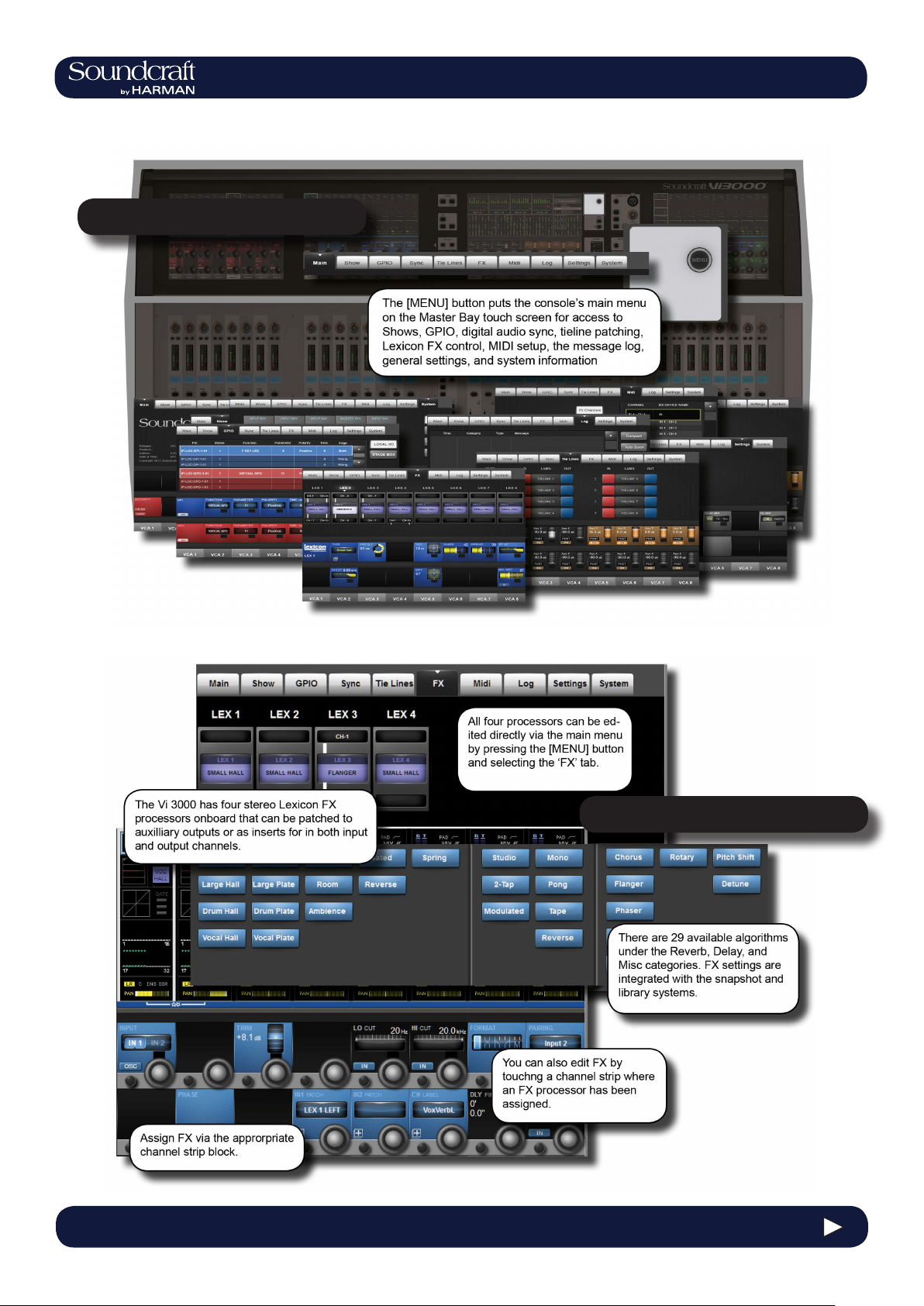
Main Menu System
Vi3000 USER MANUAL
3.0 QUICK START
Lexicon FX
3.0 - 9 3.0 QUICK START
Page 21
Vi3000 USER MANUAL
®
4.1: Hardware > Local I/O
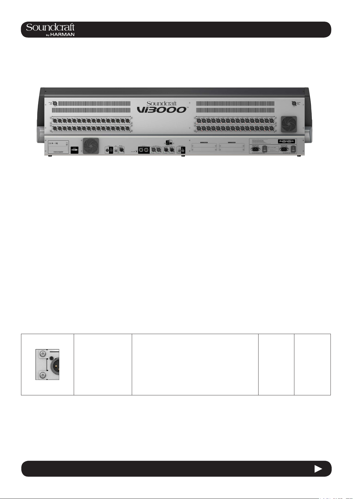
Hardware - Local I/O
Most of the Vi3000 local I/O is located on the rear panel of the console. The main I/O slots have a variety of possible
congurations, inlcuding digital (AES) and analogue input and output cards. However, the monitor / masters output
section cannot be changed - this contains the xed-routing Monitor A and Monitor B outputs, plus the master LCR
analogue outputs.
There are also user-congurable D21m I/O expansion slots that can accept any of the available Soundcraft D21m
compatible I/O cards. Options for these include MADI (Optical or CAT 5), ADAT, Blu Link, Aviom, Ethersound, Cobranet, Line in, line out, AES/EBU, and mic in. The D21m IO Expansion slots are also used for connecting a Soundcraft Stagebox.
Fixed I/O on the rear panel includes all data/digital connections such as MIDI, USB, HiQnet, AES I/O, DANTE, MADI,
Word Clock, and DVI Out, plus the dual redundant power supply connections.
There are also two 12v lamp connections.
The control surface of the console features two additional USB sockets and a talkback microphone XLR connection.
Main I/O Slots
The monitor / masters output section cannot be changed
(bottom left of the main picture) as this contains the
xed-routing Monitor A and Monitor B outputs, plus the
master LCR analogue outputs.
The main local I/O slots.
Conguration options for the other slots are: 32 mic in/32
line outs, 48 mic in / 16 line out (the upper line out card
is replaced by a mic in 33-48 card), 16 mic in / 16 in 16
out AES / 16 line out (the mic in 1-16 card is replaced by
a blank, the upper line out module 1-16 is replaced by a
16 in 16 out AES module).
4.1 4.1: Hardware > Local I/O
Page 22
®
®
PSU / Power
Sockets
4.3: INPUT CHANNEL > DYNAMICS
Vi3000 USER MANUAL
Vi3000 USER MANUAL
4.1: Hardware > Local I/O
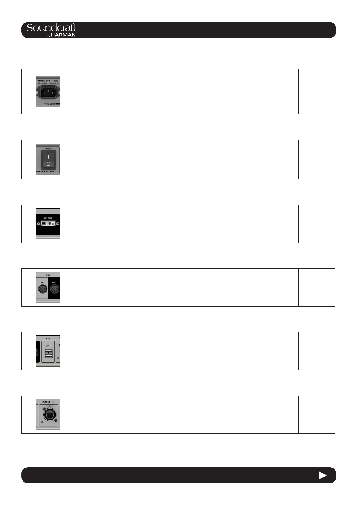
There are two mains
inputs for seamless redundancy for those that
require it. The IEC inlets
can accept AC inputs
from 100V to 240V.
Either socket can be used for a single supply. if both are
used then one is a backup. The two sockets are labelled
PSU1 and PSU2, corresponding to indicator lights on the
Menu-System-Local page. The colour of this indicator,
and the power button on front panel of the console, indicates the state of these PSUs: RED if only one of them
is on, and GREEN if both are on.
Power
Switches Inactive Active
There is a power switch
for each of the power
supply inputs. Both
need to be on for the
dual redundancy switching to be effective.
Power off Power on
DVI (Digital
Video) output
For future use.
MIDI In / Out
USB
HiQnet
Interface
5-Pin DIN connectors
for MIDI compatible
equipment only.
The console USB connections ca be used for
connecting an external
keyboard or for USB
storage devices.
XLR-housed EtherCon
connector for HiQnet
network connection.
For details on HiQnet setup, please refer to reference
chapter 18.
4.3 INPUT CHANNEL > De Esser
4.1 4.1: Hardware > Local I/O
Page 23
®
AES I/O
Vi3000 USER MANUAL
4.1: Hardware > Local I/O
DANTE
MADI I/O
2 x 3-pin XLR AES (twochanel) digital audio
input and output.
Input and output
Interface ports for a
a DANTE (Audinate)
digital audio network.
Input and output Interface ports for connection to/from MADI-compatible equipment.
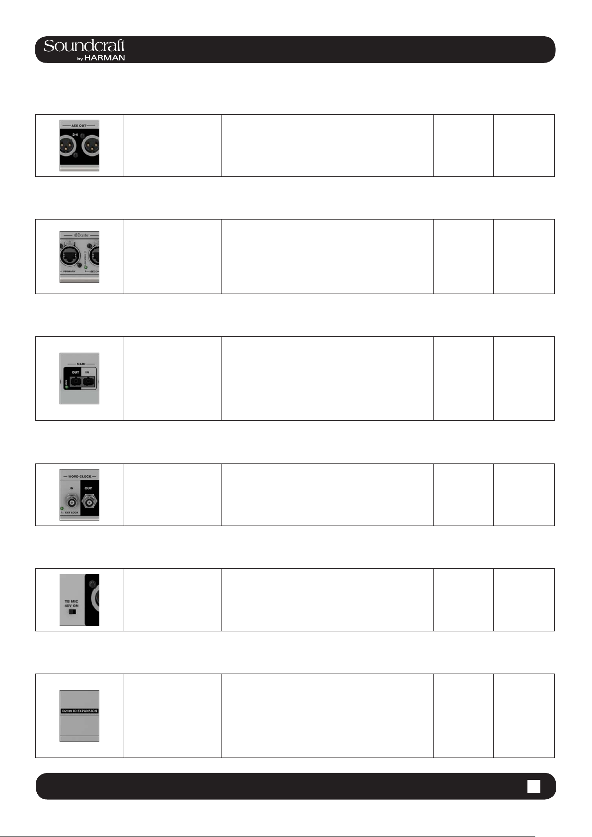
4 channels of AES/EBU format outputs and 4 channels
of inputs.
AES 1-2 and 3-4 Input sockets have associated green
condence LEDs that indicate a valid sync signal is
present.
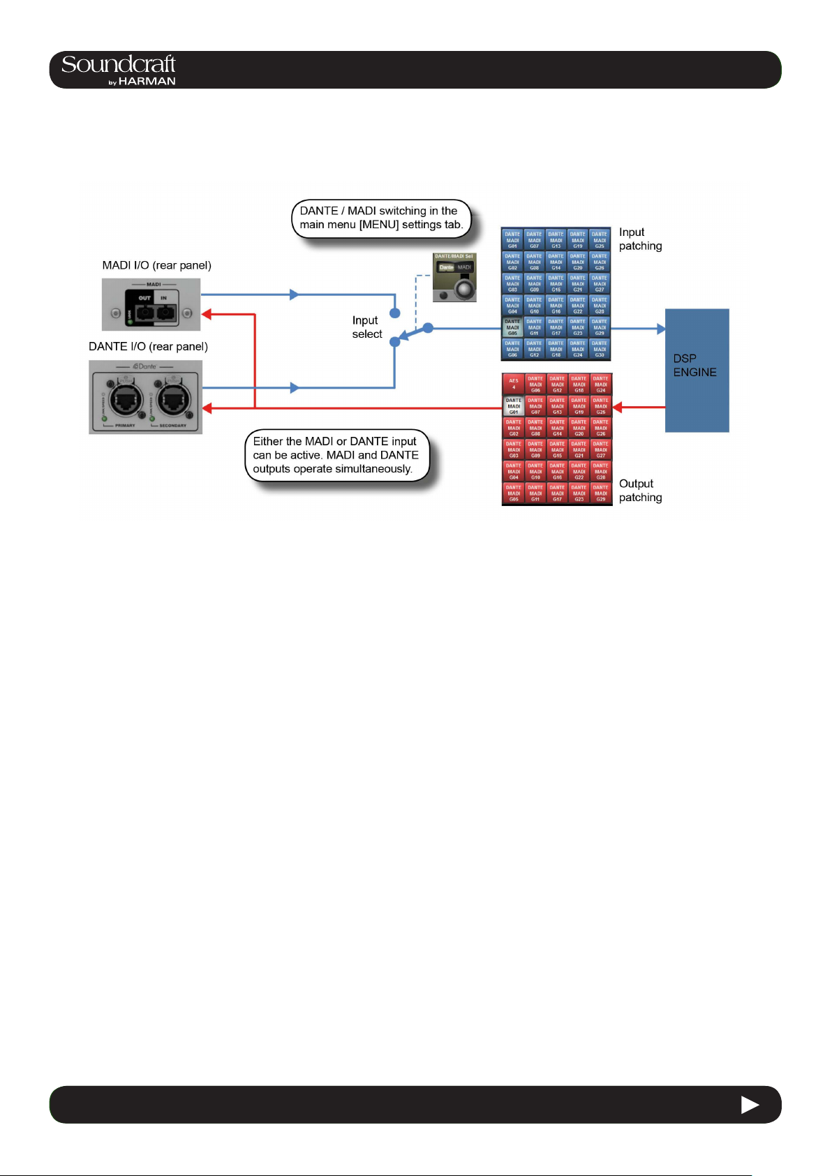
Please note, the Vi 3000 MADI local MADI and DANTE
ports share an input and so are exclusive. That is, you
can choose either a local MADI or DANTE input. The
outputs are 'parallel' and a work concurrently. The choice
between the MADI and DANTE inputs is determined by
the DANTE/MADI global switch in the Setting tab of the
main menu - accessed with the [MENU] button.
Connections are via multimode SC connectors.
Wordclock I/O
Outputs console
wordclock or syncs to
external wordclock at
48kHz.
Talkback Mic
48V Inactive Active
Switch to apply 48V
phantom power to the
talkback mix input on
the top panel of the
console.
No Power
phantom
powered
D21m Slots
These card slots can be used for any available D21m
option cards of which there is a large range including
D21m Slots, labelled
slots I, J, K, and L.
MADI (Cat 5 or Optical) Stagebox connection, ADAT
(16ch single slot), Blu Link (32ch single slot), Aviom (16
ch single slot), Ethersound (64ch double slot), Cobranet
(32ch single slot), Line in (8ch single slot), line out (8ch
single slot), AES/EBU (16ch double slot), and mic in (4ch
single slot).
4.1 4.1: Hardware > Local I/O
Page 24
4.3: INPUT CHANNEL > DYNAMICS
®
®
Vi3000 USER MANUAL
Vi3000 USER MANUAL
4.2: Hardware > DANTE / MADI Sources
DANTE / MADI Interface and switching notes
The Dante/MADI interface gives the Vi3000 a lot of exibility for recording shows, Virtual Soundchecking or interfacing
with third party MADI or Dante-enabled equipment such as signal routers or system processors.
The interface comprises an input (64ch) in each format and an output (64ch) in each format. The outputs are fed by a
common signal source which is available to any channel or bus via the Dante/MADI buttons within the Local tab of the
console’s output patching matrix. The patched signal is fed to both Dante and MADI outputs simultaneously.
The inputs are selectable using a global switch in the Menu-Settings page of the console to choose either the Dante or
the MADI port as the active input. Whichever of these is selected will appear in the Local tab of the input patch matrix
in the console and will be labelled Dante or MADI as appropriate. Only one input can be used at a time.
Recording
64ch recording/replay is possible via the MADI interface using a third-party MADI interface such as RME MADIface,
in most cases the recording software can be set to take its clock source from the console’s MADI stream. Alternatively
the console’s Wordclock Out can be used to drive the recording software or router, or the console can be slaved to the
other equipment’s clock via Wordclock In.
Alternatively, 64ch recording/replay can be achieved via the Dante port, by simply installing a copy of the Dante Virtual Soundcard driver (DVS), available from the Audinate website. A free one-off license token is included with every
Vi3000 console -see the documentation packaged with the console. The license token number is used on the Audinate website to enable the issuing of a license key code which is then entered into the DVS boot screen to unlock the
software. Dante Virtual Soundcard is available in PC and Mac formats and allows the the standard ethernet port on the
computer to become visible as a 64ch input/output low-latency audio interface from any audio recording or processing
software.
Interfacing to another Dante-enabled device or network
The Dante interface allows connection to any other Dante-enabled device, either directly or via a network switch,
and using either normal or redundant connections depending on how the primary and secondary Dante ports of each
device have been congured. Although the patching of signals to/from channels or busses in the console is done via
the console’s patch matrix, the routing of those 64 in and out signals within the Dante network has to be set up using
a free software application called Dante Controller, available from the Audinate website and running on either a PC or
Mac external computer. Using this software it’s possible to make connections on an individual channel basis between
the Vi3000’s 64ch Dante interface and all other Dante equipment on the network.
4.3 INPUT CHANNEL > De Esser
4.2 4.2: Hardware > DANTE / MADI Switching
Page 25
Vi3000 USER MANUAL
®
4.2: Hardware > DANTE / MADI Sources
Syncing with Dante equipment
Detailed setup of Dante network is beyond the scope of this User Guide (see user-guide documentation for Dante
Controller software for more details), but it important to understand the concept of synchronisation within a Dante network, even if there are only two devices in the network. In any audio network there must be one device acting as clock
master, the others are then slaves. In the Dante network, this device is known as the Primary Master. There can also
be secondary masters - these are devices that are normally slaves but will take over the role of Master clock should
the designated Master fail or be disconnected from the network. The status Primary/Secondary Master/Slave must be
set for each device, including for the Vi3000, using external Dante Controller software - it cannot be done from within
the console’s software. (Note: The Vi3000’s Dante interface is set as factory default to act as Primary Master).
The status of the Vi3000’s clock cong must be setup to work correctly with the Dante interface, depending on whether
the console is acting as Master or Slave on the network:
Console acting as Primary Master Select INT 48kHz clock in Menu-Sync page of console. Check ‘Slave to ext
wordclock’ in Dante Controller software for Vi3000 Dante interface
Console acting as Slave on Dante
network.
Select DANTE external clock in Menu-Sync page of console. Check ‘Slave to
ext wordclock’ in Dante Controller software for Vi3000 Dante interface.
Note: The option ‘Slave to External Wordclock’ in Dante Controller software is confusingly named as far as Vi3000 is
concerned, it actually refers to whether the Dante interface itself within the Vi3000 is locked to an ‘external’ clock - in
this case meaning the INTERNAL w/clock of the Vi3000 itself. If the Slave to Ext Worclock box is NOT checked, then it
means the Dante I/F will sync to network clock, ie the clock of the Primary Master.
See Chapter 16: Main Menu, Sync page for further info.
4.2 4.2: Hardware > DANTE / MADI Sources
Page 26
®
Vi3000 USER MANUAL
5.0 Operations Overview
5.0: Operations Overview
5.0 5.0 Operations Overview
Page 27
4.3: INPUT CHANNEL > DYNAMICS
®
®
Vi3000 USER MANUAL
Vi3000 USER MANUAL
5.1 Operations Overview > Conventions
5.1: Conventions And Colours
This manual, and the console uses certain conventions to make things signicantly easier for the user. This includes
the unique FaderGlow technology that can dynamically colour code console faders depending on their current assign-
ment.
Conventions used in this manual
Three types of brackets are used to indicate the type of control being refered to.
[ ] is used to indicate a panel-mounted key or encoder.
{ } is used to indicate a Vistonics™ (VST) key or encoder.
( ) is used to indicate a button on a touch-screen.
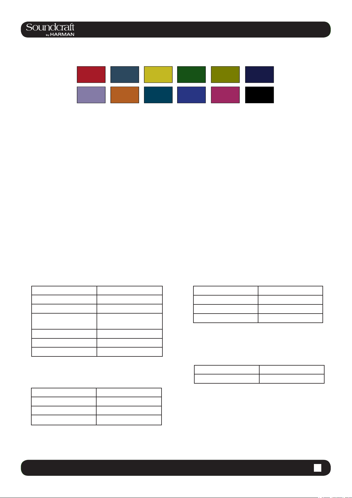
COLOURS
The following table shows colours used in the VISTONICS screens, and in the headers and footers of the pages in this
manual:
Audio Processing
Input Functions Blue
Equaliser Red
Filter Blue
Gate,Comp,Lim,De-
Green
VCA/MG Indication
VCA 1..8 Blue
VCA 9..16 Pink
Aux VCA Master 1..16 White
Mute Group Red
ess
Pan, Dir Out, Insert Yellow
Oscillator Gold
Monitoring Lilac
Patching & Misc
Input Patch Blue
Busses
Output Patch Red
Aux Orange
Audio Group Green
Matrix Cyan
4.3 INPUT CHANNEL > De Esser5.1 5.1 Operations Overview > Conventions
Page 28
®
Vi3000 USER MANUAL
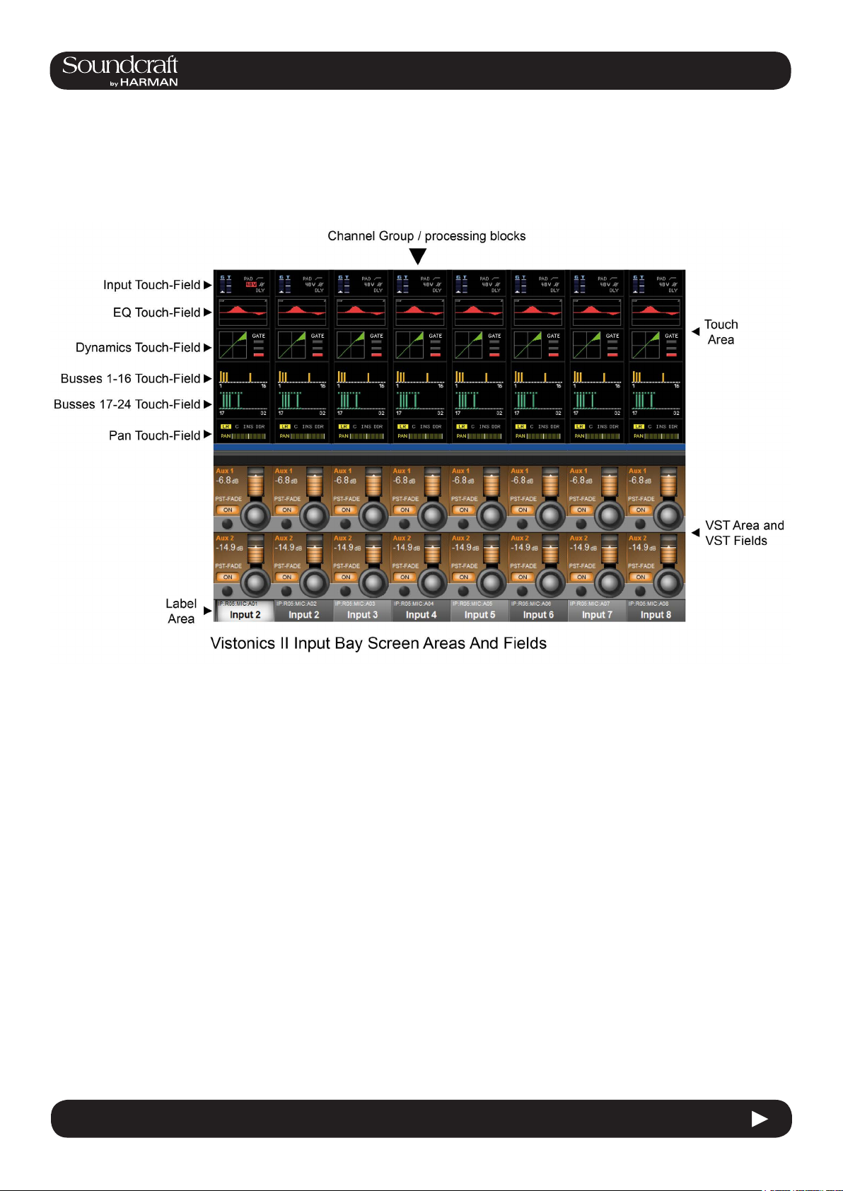
5.2 Operations Overview > Vistonics II
5.2: Visonics Overview
Vistonics II is a unique control and display technology derived from the Studer Vistonics technology and exclusive to
Soundcraft. The Vi3000 uses Vistonics II as a core technology for console operation because of its signicant user-interface benets.
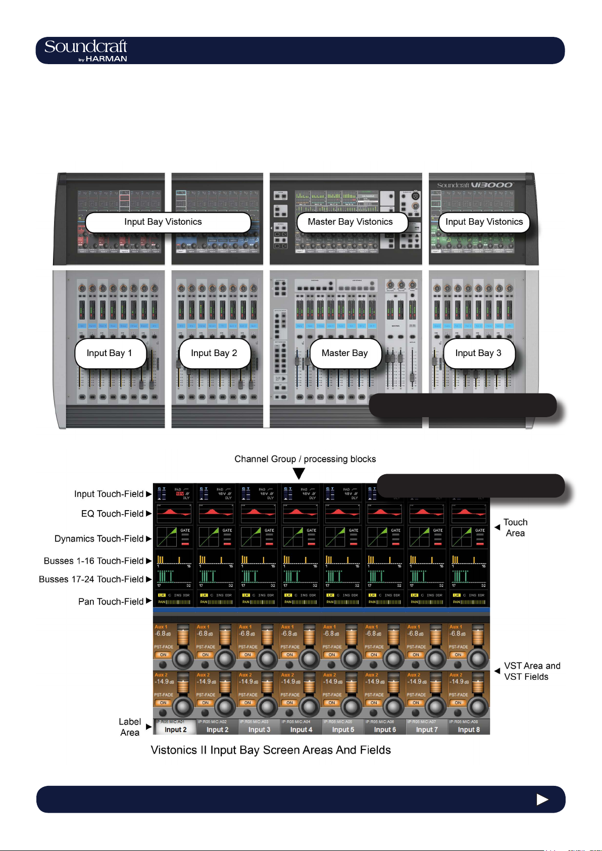
The Vistonics screens are divided into two main areas. The top section is the touch screen area and serves a number
of functions. For instance, in the default input chanel mode, the input touch screens show the Input, EQ, Dynamics,
Bus outputs, and panning sections of input channel strip. Touching one of these opens that channel section onto the
Vistonics VST area.
The VST area is the lower section of the Vistonics screens, each with two rows of eight VST Fields. Each VST Field
contains an encoder, a button, and a display area. VST Fields are normally used for individual parameter control. For
instance, the default input Vistonics screen uses the upper row of encoders to control a channel’s contribution level to
the Aux 1 bus, and the upper row of buttons to turn those contributions on and off.
5.2 5.2 Operations Overview > Vistonics II
Page 29
®
®
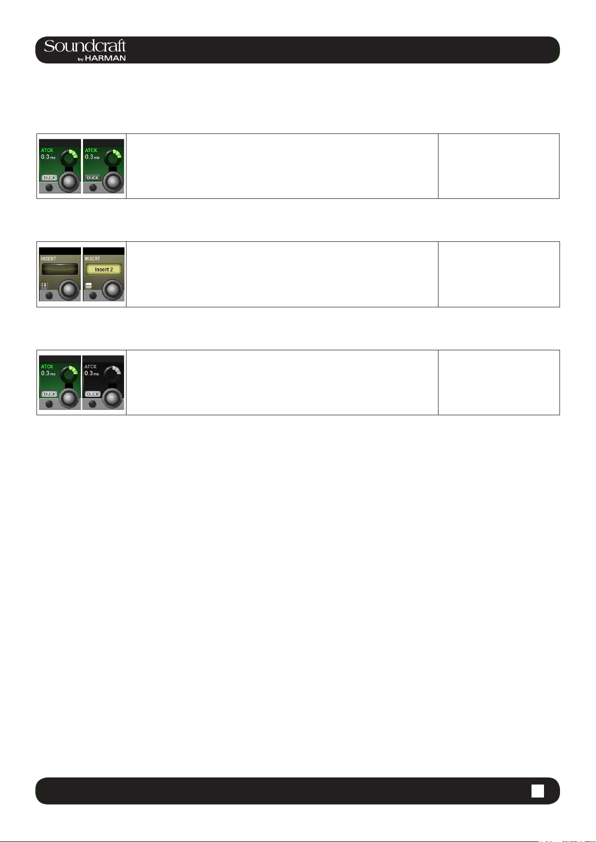
Buttons On/Off
Open Touch
Page
4.3: INPUT CHANNEL > DYNAMICS
Vi3000 USER MANUAL
Vi3000 USER MANUAL
If a function is assigned to a button it is displayed as shown. The 'active' state shows
the button highlighted in a lighter colour.
If the button can open a conguration page in the Touch area it shows a '+' sign on
the button. If the conguration page is already open, the button will be labelled with a
'-' sign. Pressing the button in that state will exit the conguration page.
5.2 Operations Overview > Vistonics II
Inactive Fields
If an audio function block is disabled, with the background of the eld changed to
grey, the button indication will change to a darker colour.
4.3 INPUT CHANNEL > De Esser5.2 5.2 Operations Overview > Vistonics II
Page 30
®
Vi3000 USER MANUAL
5.3 Operations Overview > Console Bays
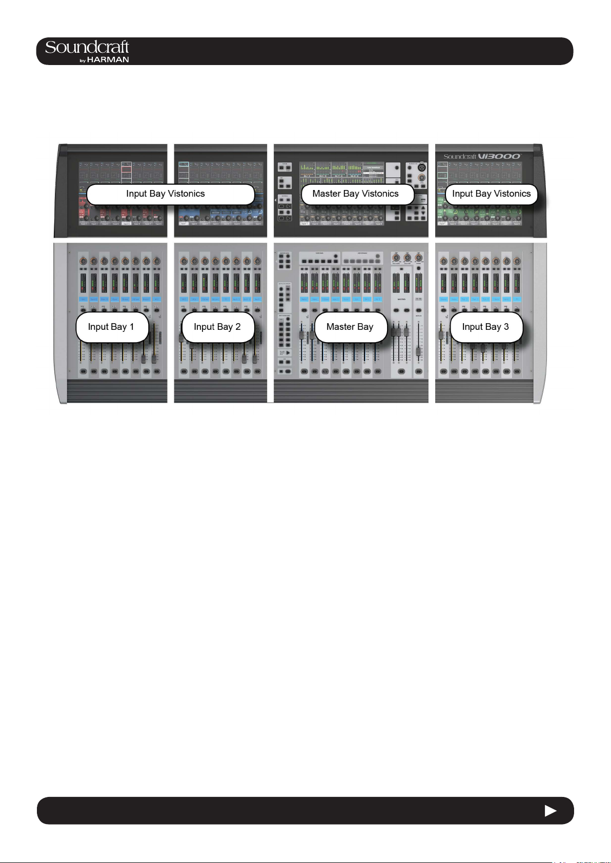
5.3: Console Bays
The Console is divided into four main bays. Counting from the left, the rst, second, and fourth bays are Input Bays.
The third bay is the Master Bay.
Input bays normally control input channels, however, they can have other functions mapped to them depending on
how the console is being used. For example, you can map the bus masters, graphic EQ bands, matrix mix sources,
aux bus contribtions, and more to the input faders.
The input bay vistonics touch screen areas normally show eight channel-strip processing blocks for the eight corresponding faders. You can touch those processing blocks to focus the VST section (bottom part of screen populated
with encoders and buttons) on that selection.
The input bay VST areas normally show Aux 1 and 2 contributions, though the functions of these encoders are also
determined by the input channel VISTONICS button group.
The Master Bay contains asignable faders for the bus masters, plus the mix master (L, R, C) faders and the assignable monitor fader.
The Master Bay touch screen default display is an overview of metering for all input and output channels, as well as an
as system message area and cue list.
The Master Bay VST area’s default mapping is the rst 16 bus masters. The next eight masters can be accessed with
the [PAGE 2] button in the Master Bay VISTONICS button group.
5.3 5.3 Operations Overview > Console Bays
Page 31

4.3: INPUT CHANNEL > DYNAMICS
®
®
Vi3000 USER MANUAL
Vi3000 USER MANUAL
5.3 Operations Overview > Console Bays
5.3: Console Bays - Input Bay 3 Navigation
The Master Bay touch screen meters can be used as a navigation device - simply touch a block of eight meters and
those channels (both inputs and outputs) are mapped to the right-hand input bay. This is excellent for fast access and
for dual operator scenarios.
4.3 INPUT CHANNEL > De Esser5.3 5.3 Operations Overview > Console Bays
Page 32

®
Vi3000 USER MANUAL
5.4 Operations Overview > FaderGlow™
5.4: FaderGlow™
Soundcraft FaderGlow™ (Pat. Pend.) is a unique feature that gives the user an additional level of status indication,
and can signicantly reduce operating errors.
On the console, several different functions can be assigned to a particular fader, it can therefore be easy to forget
which function is currently being controlled, especially when grabbing a fader in a hurry. The main principle of FaderGlow is therefore to indicate the actual function type that is currently assigned to a particular fader. Soundcraft FaderGlow is tted to all 32 Faders that can change their function.
FADER OPERATION Soundcraft FaderGlow™ COLOUR
Channel level NONE
AUX send level ORANGE
GRP (fader closed) GREEN
MTX contribution level CYAN
VCA Master 1..8 BLUE
VCA Master 9..16 PINK
Aux VCA Master 1..16 WHITE
5.4 5.4 Operations Overview > FaderGlow™
Page 33

4.3: INPUT CHANNEL > DYNAMICS
®
®
Vi3000 USER MANUAL
Vi3000 USER MANUAL
5.5 Operations Overview > Buttons
5.4: Buttons
There are a wide variety of button groups on the Vi3000. Below are described all button groups and selected individual
buttons. Please refer to the relevant reference section for detailed information on the operation of all buttons.
Most buttons on the console can be latching (stay on) or Momentary (on when pressed, off when you let go) If you
hold a button down it will have a momentary action. If you press a button and let go within half a second it will ‘latch’.
System Button Group
[MUTE ALL O/P] (Mute All Outputs) and [POWER ON] buttons.
Edit Button Group
[COPY], [PASTE], and [UNDO] buttons.
These are used for copying and pasting whole channels, processing blocks, and individual parameters either elsewhere on the console or to and from the console’s powerful library system.
For more information see the Edit System reference chapter 13.
4.3 INPUT CHANNEL > De Esser5.5 5.5 Operations Overview > Buttons
Page 34

®
Vi3000 USER MANUAL
5.5 Operations Overview > Buttons
Input Channel VISTONICS Group
The input channel VISTONICS control buttons provide convenient ways of assigning bus
master functions to the input channel VST encoders, such as selections for individual bus ‘tap’
points, and getting the input bus contribution shown on the VST screen to follow the master
bus selection in the Master Bay.
For more information, see the Inputs reference chapter 6.
Output Vistonics Group
These buttons provide control over the VST section functionality of the Master Bay vistonics
screens. For example, the [PAGE A] and [PAGE B] buttons switch the encoder section of
the screen between busses 1-16 and 17-24. For More information, see Outputs Reference
chapter 7.
Encoder Mode Buttons
These buttons assign various functions to the input channel strip encoders. For more information see the Inputs reference chapter 6.
Mute & VCA Groups
Control and assign the four mute groups and available 16 VCAs. For more information see the
Mute & VCA Groups reference chapter 9.
5.5 5.5 Operations Overview > Buttons
Page 35

4.3: INPUT CHANNEL > DYNAMICS
®
®
Vi3000 USER MANUAL
Vi3000 USER MANUAL
5.5 Operations Overview > Buttons
Input Fader Pages
These buttons control navigation through ve basic input channel Pages/Layers, including the ‘All
Busses’ view, plus ve user-denable pages. These buttons only affect the three input channel
bays. For more information see the Input Channels reference chapter 6.
Output Fader Pages
Navigate through eight-wide pages of the console’s output
busses and VCA masters. These buttons only affect the Master
Bay channel strips. For More information see the Output
Channels reference chapter 7.
Next & Last
[NEXT] and [LAST] buttons for moving through the loaded Cuelist. These buttons have to be enabled in the Settings page of the main Menu. For more information see the Snapshots, Cuelist, and
Global Filter reference chapter 14.
Snapshot Control
Full control over Snapshot and Cuelist storage, navigation, and recall. For more information see the Snapshots, Cuelist, and Global Filter reference chapter 14.
Talkback & Oscillator
Most of these buttons are dedicated to activating preset Talkback routings. To access
Oscillator functions, use the [SETUP] button. For more information see the Talkback And
Oscillsotr refence chapter 15.
4.3 INPUT CHANNEL > De Esser5.5 5.5 Operations Overview > Buttons
Page 36

®
Vi3000 USER MANUAL
5.5 Operations Overview > Buttons
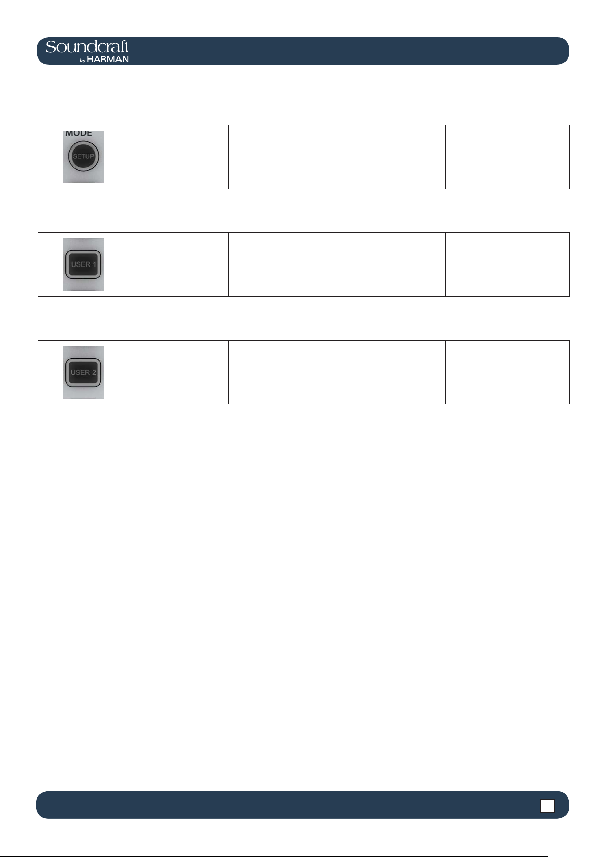
[SETUP] Buttons Field / Group: Active
[SETUP] buttons open
the relevant setup
screen in the Master
Bay Vistonics screen.
While a setup screen is active, pressing the [SETUP]
button again will close that setup screen. For more information see the chapter relevant to each [SETUP] button.
Show Setup
screen
[SOLO/SEL]
Buttons Field / Group: Inactive Active
The [SOLO/SEL] keys operate in two modes. The default
function is to enable the SOLO path from its channel or
bus to the monitoring system. However, if a touch-area
Solo or select a channel.
page is open, pressing a [SOLO/SEL] from another
channel (within its own bay of eight channels) moves the
touch-area page to this new channel. [SOLO/SEL] buttons also perform other selection functions depending on
the console mode. These are described in the relevant
reference chapter.
Normal
Soloed/Se-
lected
[GANG] Buttons Field / Group: Inactive Active
Special Ganging functionality.
For linking channels, processing blocks, and parameters,
for convenient control. See the Gang section in this operations overview chapter for more information.
Normal Gang Mode
[SOLO CLEAR]
Button Field / Group: Active
Clear any currently
active console Solos.
Clear
5.5 5.5 Operations Overview > Buttons
Page 37
4.3: INPUT CHANNEL > DYNAMICS
®
®
Vi3000 USER MANUAL
Vi3000 USER MANUAL
5.5 Operations Overview > Buttons
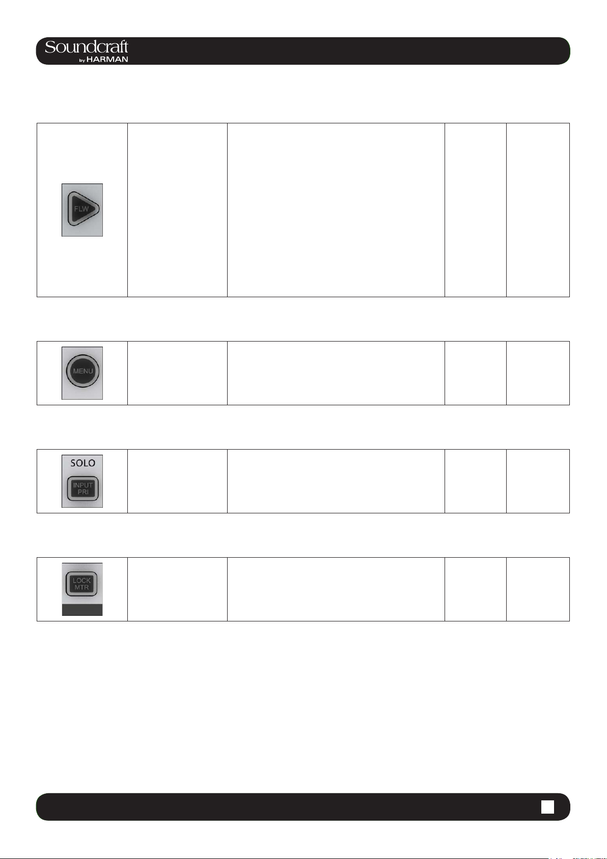
Lower [FLW]
Button Field / Group: Inactive Active
The fader FOLLOW OUTPUT SOLO [FLW] button
located near the bottom of the Master Bay buttons strip
causes the input faders to become contributions to an
output bus when its [SOLO/SEL] button is pressed (often
known as ‘Sends on Faders mode’).
If a Matrix Output Solo/Sel is pressed, regardless of the
Input faders follow master bus selection.
setting of Follow Solo modes, the Output Solo will be
activated, the EQ/Dyn/Misc touch screen for the Matrix
Output displayed, and the channel faders will be assigned to the contribution levels from the Outputs to the
Soloed Matrix Output.
Note: the lower [FLW] key has an additional function
in allowing VCAs to control the Aux sends of input
channels. See the Mute & VCA reference chapter 9 for
details.
Follow Mode Normal
Main Menu
Button Field / Group: Inactive Active
Brings up the Main
Menu screen in the
Master Bay.
Settings and preferences for a variety console functions
are arranged in tabbed pages in the main menu. For
more information, see the Main Menu reference chapter
16.
Normal
Main Menu
Active
Input Priority Field / Group: Inactive Active
Allow an Output Solo to
remain active, whilst an
Input Solo is temporarily
activated ‘over the top’
of it.
For more information see the SOLO System reference
chapter 8.
Normal
Main Menu
Active
Lock Meters Field / Group: Inactive Active
Locks the Meter section
of the Master Bay touch
screen onto the screen.
The meter section will be safe from output selections
bringing the channel up on the touchscreen, for example.
[SETUP] buttons still takeover the screen though.
Normal
Meters
Locked
4.3 INPUT CHANNEL > De Esser5.5 5.5 Operations Overview > Buttons
Page 38

®
Vi3000 USER MANUAL
5.6 Operations Overview > Encoders
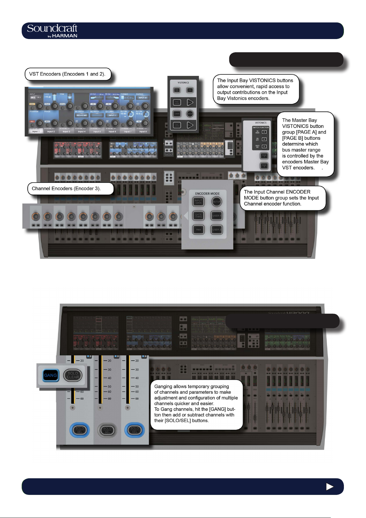
5.6: Encoders
Each input channel strip contains three encoders: encoder 1 and encoder 2 are located in the VST elds in the lower screen area, while the channel encoder is located at the top of the fader area, and has an LED ring to indicate its
parameter state. Each of these encoders can control different parameters, depending on the settings of other parts of
the console.
The master section has 16 VST encoders and 4 panel-mounted encoders with LED rings: the TB/OSC Level Control
encoder, and the Sold Blend, Solo Trim & Phones Volume encoders. These last four are dedicated to their respective
functions.
Channel encoders always control a parameter on their own channel strip. The function of the channel encoders can
be globally selected via the [INPUT GAIN], [GATE THRS] and [PAN] keys on the Encoder Mode panel. See the Inputs
reference chapter 5 for more information.
The VST Input Bay encoders default to Aux 1 and 2, though can be assigned a variety of functions depending on the
console mode. If any touch eld is activated, the 16 VST encoders are assigned with expanded channel function parameters. See the Inputs reference chapter 5 for more information.
The default setting for the Master VST encoders is as the output level controls for Master Outputs 1-16. This can also
be selected by pressing the [PAGE A] key on the Master Vistonics Mode Panel. Pressing [PAGE B] will cause the Master VST encoders to be assigned as the output level controls for Master Outputs 17-24.
The Master VST encoders can also be assigned to Master Output Expanded Functions (e.g. EQ, Dynamics, etc.).
When a Master Output [SOLO/SEL] key is touched, it opens the Processing Area in the Master VST screen. If then a
paticular touch-area is touched, the VST encoders are assigned to appropriate expanded functions. For more information see Outputs reference chapter 6.
5.6 5.6 Operations Overview > Encoders
Page 39

4.3: INPUT CHANNEL > DYNAMICS
®
®
Vi3000 USER MANUAL
Vi3000 USER MANUAL
5.7 Operations Overview > Gangs
5.7: Gangs
Gang is a very helpful feature to speed up operations that inuence functions on multiple input channels, or on output
busses, in the same way. Any parameter change on ganged channels will be applied to all other ganged channels as
an offset. For example, adding 4dB of level to an aux send on one channel will add 4dB of level to the the corresponding Aux sends on all other ganged chanels - it will not ‘copy’ the actual level to the other ganged channels.
Button presses will change any corresponding buttons in ganged channels that are not currently in the new state, to
the new state. From that point on, further presses will result in all switches changing state together.
Gang mode is activated and deactivated with the [GANG] button. You add or remove channels to or from the gang with
the channel [SOLO/SEL] buttons.
Entering Gang Mode does not cancel any solos of any type that are active at the time. The Solo system continues to
work as it was when Gang Mode was switched ON. The amber ‘Solo’ illumination of the Solo/Sel switches cannot be
seen whilst gang mode is ON.
Gang Button Field / Group: Inactive Active
After activating Gang Mode, hold the [GANG] button
Activate or deactivate
Gang Mode.
down to Gang all channels.
You can leave Gang Mode pressing the [Gang] button.
If you haven’t ‘cleared down’ the gang then it will be
restored the next time you re-enter Gang Mode.
Normal Gang Select
Select (Gang) Field / Group: Active
When in Gang Mode you can add single channels by
pressing individual channels' [SOLO/SEL] buttons OR
you can add a range of channels by pressing the rst
and last channels' [SOLO/SEL] buttons together.
Select and deselect
ganged channels.
Press & Hold any [SOLO/SEL] button to clear down the
entire gang (recommended after use to avoid accidental
operation of Gang mode).
When in a gang, a channel’s [SOLO/SEL] button will
glow blue.
Select
Channel
4.3 INPUT CHANNEL > De Esser5.7 5.7 Operations Overview > Gangs
Page 40

®
Vi3000 USER MANUAL
5.8 Operations Overview > Labelling
5.8: Labelling
The console labelling system is displayed on a touch-screen area whenever the labelling of a channel, output, cue, le,
or other named parameter or item is required. For example, you can label an input channel by touching the channel’s
input area on the touch screen then pressing the {CH LABEL} button in the VST area.
Labelling can be done with the displayed on-screen keyboard or an external USB keyboard. The on-screen keyboard
is context sensitive and shows only the allowed character and symbols.
Long Labels can contain up to 10 characters and short labels can contain up to six characters.
5.8 5.8 Operations Overview > Labelling
Page 41

®
Vi3000 USER MANUAL
®
Vi3000 USER MANUAL
6.0: INPUTS
6: Input Channels
Bays 1, 2, and 4 of the console (Input Bays 1, 2, and 3) are normally dedicated to controlling input channels. However,
other functions can be mapped to these channels, such as the Master Busses, Matrix feeds, Graphic EQ, and so on.
There are four main input channel control areas on the console:
• The main channel strips, including the Vistonics screen sections, are for control of input chanel parameters, routing,
and patching.
• The INPUT FADER PAGES buttons are for navigating the available input channels by choosing preset and user-
denable fader pages.
• The input channel VISTONICS control buttons provide convenient ways of assigning bus master functions to the
input channel VST encoders.
• The ENCODER MODE buttons provide fast switching of the channel strip encoder functions.
6.0 6.0: INPUTS
Page 42

®
Vi3000 USER MANUAL
6.1: INPUT CHANNEL > FADER PAGES
Navigating The Input Channels - Input Fader Pages
This section is used for navigating Fader Pages (or layers). There are four main layers of 24 input channel strips, and
a further ve user-denable layers available. The [ALL BUSSES] button maps the output busses to the input channel
strips, as described further in the Outputs reference section.
In addition, you can touch the input meter elds in the Master Bay Vistonics to remap those input channels to the right-
most input bay.
6.1 6.1: INPUT CHANNEL > FADER PAGES
Page 43

Vi3000 USER MANUAL
®
6.1: INPUT CHANNEL > FADER PAGES
Fixed Fader
Layers
User Fader
Layers
All Busses
Mode
Field / Group: INPUT
FADER PAGES Active
Select four pages/layers
of input channel strips.
Field / Group: INPUT
FADER PAGES Active
User-Dened input
channel strip pages/
layers
Field / Group: INPUT
FADER PAGES Active
Map the 24 output
busses to the input bay
fader strips.
Each button maps Pages of 24 channels to the three in-
put bays, so [A] is channels 1-24; [B] is channels 25-48;
[C] is channels 49-64; and [D] is channels 65-96.
Select one of these buttons to map that user-dened
fader-layer to the console. The User layers are dened
by pressing the FADER PAGES [SETUP] button.
See Outputs Reference section 7 for more detail on All
Busses mode.
Select
Select
Select
6.1 I6.1: INPUT CHANNEL > FADER PAGES
Page 44

®
Vi3000 USER MANUAL
6.2: INPUT CHANNEL > CHANNEL STRIP
The Input Channel Strip
Input Channel
Strip Encoder Field / Group: Range Low Range High
Rotary control whose
function is dened by
the input ENCODER
MODE buttons.
The Default function is control over the channel’s analogue input gain.
For more information see the Inputs Encoder Mode reference section 6.3
Dependant
on Mode
Dependant on
Mode
Input Channel
Strip F Field / Group:
Reserved for future
software updates
6.2 6.2: INPUT CHANNEL > CHANNEL STRIP
Page 45

Vi3000 USER MANUAL
®
6.2: INPUT CHANNEL > CHANNEL STRIP
Input Isolate Field / Group: Active
Used to isolate the
channel (and selections) from snapshot
recall and (when Global
Filtering is active) from
Show le loads.
See the Snapshot and Global Filtering reference section
14 for more information.
Isolate
Level and GR
Meter Field / Group:
Level and gain reduction metering for the
input channel.
See the metering reference section 12 for more information.
Input Channel
Label Field / Group:
Displays the short label/
name of this channel.
The long and short channel labels are set in the channel's 'Input' Vistonics parameter block. See reference
section 6.5.1 for more information.
'Pre' Indicator Field / Group:
Reserved For Future
Use.
Channel ON/
OFF Field / Group: Inactive Active
Channel [ON]/OFF button. 'OFF' is effectively
a mute control.
The button glows green when the channel is 'On'. If
the channel is off there is no glow colour. However, if
the channel is muted because a mute group has been
activated, the [ON] button will glow red.
Channel Off Channel On
Mute Safe Indicator Field / Group:
Glows red when Mute
Safe is active for this
channel.
When the Mute Safe system is enabled (in Monitoring
section [SETUP]), then the channel strip SOLO/SEL
button activates the Mute Safe status for the channel.
6.2 6.2: INPUT CHANNEL > CHANNEL STRIP
Page 46

®
Mute/VCA
Group Indicators Field / Group:
Vi3000 USER MANUAL
6.2: INPUT CHANNEL > CHANNEL STRIP
Shows the Mute or VCA
Groups that is channel
belongs to.
Channel Fader Field / Group:
Control the channel
output level.
FaderGlow Field / Group:
The channel fader is
colour-coded depending
on its function.
The actual target of these LEDs (Mutes, VCAs 1-8, or
VCAs 9-16) is determined by the DISPLAY buttons in the
MUTE & VCA GROUPS button group. See the Mute &
VCA Groups reference section 9 for more information.
The input channel faders can also be assigned to follow
the bus master selection in the Master Bay with the fader
[FLW] button and become level controls for contributions
to that bus.
Input channel levels are not colour-coded. The other
FaderGlow colours are Aux Sends: ORANGE; Groups:
GREEN; Matrix Contribution: CYAN; VCA Master 1-8:
BLUE; VCA Master 9-16: PINK.
Solo / Select Field / Group: Active
If a touch-panel screen is open for the for another chan-
Default is the channel
Solo function (listen to
this channel only on the
monitor bus).
nel in the same bay, the [SOLO/SEL] button moves the
touch screen to this channel. The button has other functions in other console modes such as selecting channel
for a Copy or Paste edit function. Other functions for the
[SOLO/SEL] button are detailed in the appropriate reference sections. For more on the console Solo System see
reference section 11 for more information.
Solo Enable
or Select
6.2 6.2: INPUT CHANNEL > CHANNEL STRIP
Page 47

Vi3000 USER MANUAL
®
®
Vi3000 USER MANUAL
6.3: INPUT CHANNEL > ENCODER MODE
Input Encoder Mode
These buttons determine the function of the input channel encoder at the top of the main channel strip.
If [ALL BUSSES] is active or a Matrix output is soloed, the channel encoders are disabled and have no function (the
previous function is remembered however).
Mode: Input
Gain Field / Group: Active
(Default) Switch the input Encoders to control
analogue input gain.
Mode: Gate
Threshold Field / Group: Active
Switch the input Encoders to control Gate
Threshold.
Select Mode
Select Mode
Mode: Pan Field / Group: Active
Switch the input Encoders to control Pan.
Select Mode
6.3 6.3: INPUT CHANNEL > ENCODER MODE
Page 48
®
Vi3000 USER MANUAL
6.3: INPUT CHANNEL > ENCODER MODE
Setup Field / Group:
Reserved for future
software upgrade.
Mode: User 1 Field / Group: Active
Switch the input Encoders to control Compressor Threshold.
Select Mode
Mode: User 2 Field / Group: Active
Switch the input Encoders to control Digital
Trim.
Select Mode
6.3 6.3: INPUT CHANNEL > ENCODER MODE
Page 49

Vi3000 USER MANUAL
®
®
Vi3000 USER MANUAL
6.4: INPUT CHANNEL > VST CONTROL
Input VISTONICS Buttons (VST Section Control)
These buttons control the functionality of the input channel VST encoders.
You can easiliy and rapidly assign bus contributions and bus panning to the encoders using this button group.
Pre/Post Field / Group: Active
Congure Aux sends
from channels (when
they are assigned to the
two VST encoder rows),
as pre or post-fader.
VST Mode: Pan Field / Group: Active
If a stereo Aux is assigned to a VST encoder row, and
if the [PAN] key is active, the encoder will control the
Activate aux paning
for encoders where
applicable.
Aux Pan rather than the contribution level. If both Auxes
assigned to Row 1 & 2 are Stereo Auxes, both Rows 1
and 2 will change to the PAN function across the desk. If
only one of the two rows is a Stereo Aux, then only this
row will change to PAN. If neither row has a Stereo Aux
assigned, the [PAN] switch will have no function.
Activate
Mode
Fast Assign Field / Group: Active
Provides a very fast way
to temporarily assign a
bus function to a VST
encoder row.
Press and hold one of the [FAST ASSN] keys, then press
one of the Output Masters’ [SOLO/SEL] keys.The rele-
vant row of VST encoders will now be assigned to that
Output master, and the [FAST ASSN] key in question
will illuminate. There will be no inuence on audio, the
Output solo is not activated.
Activate
Mode
6.4 6.4: INPUT CHANNEL > VST CONTROL
Page 50

®
Vi3000 USER MANUAL
6.4: INPUT CHANNEL > VST CONTROL
Ecoders Follow
Masters Field / Group: Inactive Active
Activate the FOLLOW
SOLO function for the
respective VST encoder
rows.
Pressing a bus master [SOLO/SEL] button will automatically assign the soloed bus master to this row, overriding
the default or the [USER] layer. Note that only one [FLW]
can be active at a time.
Activate
Mode
VST Mode:
USER Field / Group: Inactive Active
Assign the two VST
Encoder rows as AUX
3 and AUX 4 send level
controls for their input
channels.
Activate
Mode
Input VST
setup Field / Group: Inactive Active
Reserved for future use.
Activate
Mode
6.4 6.4: INPUT CHANNEL > VST CONTROL
Page 51

Vi3000 USER MANUAL
®
®
Vi3000 USER MANUAL
6.5.1: INPUT CHANNEL > INPUT
Input Touch Screen Audio Blocks - INPUT
A mono input channel’s input section touch screen area is at the top of the Vistonics input channel strip area,
colour-coded blue. The input section consists of that channel’s input source selection, pre-amp and gain stages
control, channel pairing selection for stereo (and other format) channel creation, channel labelling, and channel delay
adjustment.
6.5.1 6.5.1: INPUT CHANNEL > INPUT
Page 52

®
Vi3000 USER MANUAL
6.5.1: INPUT CHANNEL > INPUT
Channel Input
Select Field / Group: INPUT Range Low Range High
Select either Input 1 or
Input 2 as the channel
input.
The two physical channel inputs are assigned in the IN1
PATCH and IN2 PATCH elds.
IN 1 IN 2
Oscillator Input
Select Field / Group: INPUT Inactive Active
Assign the console's
central oscillator to the
input of this channel.
When OSC is active, the normal input selections are
disabled and the corresponding input touch eld is highlighted in orange.
off on
Input Gain Field / Group: GAIN Range Low Range High
Adjust the analogue
input gain.
This is an analogue gain stage, before analogue-to-digital conversion.
+10dB +65dB
Input Pad Field / Group: GAIN Inactive Active
Reduce the input sensitivity by 20dB.
When the Pad is active, the PAD text in the input touch
eld is highlighted in blue.
0dB -20dB
Input Trim Field / Group: TRIM Range Low Range High
Adjust the digital input
gain.
This is the post analogue-to-digital conversion gain, in
the digital domain.
-36dB +15dB
Analogue Lo
Cut lter Field / Group: TRIM Inactive Active
Insert the analogue (pre
AD converter) low cut
lter (only analogue
inputs).
When the analogue LO Cut lter is engaged, the LO Cut
symbol in the input touch eld is highlighted in blue. This
lter affects analogue inputs only.
Out In
6.5.1 6.5.1: INPUT CHANNEL > INPUT
Page 53

Vi3000 USER MANUAL
®
®
Vi3000 USER MANUAL
6.5.1: INPUT CHANNEL > INPUT
LO CUT Cut-Off
Frequency Field / Group: LO CUT Range Low Range High
Adjusts the LO CUT cut-
off frequency
This is part of the digital (post AD) LO CUT / HIGH CUT
section and affects all inputs. The affected frequency
range is shown graphically in the EQ section of the touch
screen.
20Hz 600Hz
LO CUT IN Field / Group: LO CUT Range Low Range High
Switch the digital LO
CUT lter in and out
When the digital LO CUT lter is switched in, the LO
CUT indicator above the response graph in the EQ touch
section is highlighted in blue.
Out In
HI CUT Cut-Off
Frequency Field / Group: HI CUT Range Low Range High
Adjusts the HI CUT lter
cut-off frequency.
This is part of the digital (post AD) LO CUT / HIGH CUT
section and affects all inputs. The affected frequency
range is shown graphically in the EQ section of the touch
screen.
1kHz 20kHz
HI CUT IN/OUT Field / Group: HI CUT Range Low Range High
When the digital HI CUT lter is switched in, the HI CUT
indicator above the response graph in the EQ section of
the touch screen is highlighted in blue.
The touch screen will show pairing candidate options for
the channel - these will be consecutive channel numbers
(horizontal neighbours) and the corresponding channels on higher and lower layers (vertical neighbours).
All channel parameters will be copied to the selected
pairing candidate and the pairing FORMAT eld will be
displayed.
The choices are LR, RL, LL, RR, MONO. If the channel
is not paired, the FORMAT eld will not be displayed.
OUT IN
No Selection
LR MONO
Channel
Selection
Channel Pairing
Selection
Pairing Format
Selection
Switch the digital HI
CUT lter in and out
Field / Group: PAIRING Inactive Active
Activate channel pairing
selection on touch
screen.
Field / Group: FORMAT Range Low Range High
Adjusts stereo format of
paired channels.
6.5.1 6.5.1: INPUT CHANNEL > INPUT
Page 54

®
Vi3000 USER MANUAL
6.5.1: INPUT CHANNEL > INPUT
Phantom Power
Field / Group:
PHANTOM Inactive Active
Apply Phantom Power
(+ 48V) to XLR patched
to this input.
When phantom power is applied to this channel's input,
the '48V' indicated (touch screen input section) is highlighted in red.
Off 48V
Phase Invert Field / Group: PHASE Inactive Active
Input Patch
Invert the phase of
audio through this
channel.
Field / Group: IN1
PATCH / IN 2 PATCH Inactive Active
Activate input patching selection on touch
screen.
When phase invert is active, the phase symbol in the
input section of the touch screen is highlighted blue.
The input patch selection screen will give you access
to all available inputs / sources, both external (local
I/O, Stage Box, MADI, and so on) and internal (Lexicon
effects). If an input channel is paired, you will also have
to option to select L or R assignment from the same
screen. The IN 1 and IN 2 eld text areas will show the
selected source.
Off 180 degrees
Inactive
Selection
active
Channel Label
Field / Group:
CH LABEL Inactive Active
Activate channel
labeling functionality on
main touch screen.
Thsi control brings up the standard ASCII keyboard
display and colour selector in order to label the channel.
You can specify short and long channel names, and a label colour. You can also use a connected USB keyboard
if available.
Inactive Active
Delay Fine
Adjust Field / Group: DLY FIN Range Low Range High
Fine adjustment of the
channel delay time.
Adjusts overall delay time in small steps. The delay
units (feet, meters, seconds etc) of adjustment can be
changed in the main Settings screen, via the [MENU]
button.
0 Seconds
Delay Adjust Field / Group: DLY Range Low Range HIgh
Adjustment of the channel delay time.
Adjusts overall delaytime. The delay units (feet, meters,
seconds etc) can be changed in the main Settings
screen, via the [MENU] button.
0 Seconds MONO
Delay In / Out Field / Group: DLY Range Low Range High
Activates the delay for
this channel.
When the channel delay is active, the 'DLY' indicator in
the touch screen input area is highlighted blue.
Out In
6.5.1 6.5.1: INPUT CHANNEL > INPUT
Page 55

Vi3000 USER MANUAL
®
®
Vi3000 USER MANUAL
6.5.2: INPUT CHANNEL > EQ
Input Touch Screen Audio Blocks - EQ
A mono input channel’s parametric EQ section touch screen area is near the top of the Vistonics input channel strip
area, colour-coded red. The EQ section consists of four parametric bands with shelving response available to the LF
and HF bands..
6.5.2 6.5.2: INPUT CHANNEL > EQ
Page 56

®
Vi3000 USER MANUAL
6.5.2: INPUT CHANNEL > INPUT
Frequency Control Field / Group: FREQ Range Low Range High
Adjust the centre
frequency (band pass)
or cut-off frequency
(shelving) of the EQ.
All changes are reected in the graphic Vistonics touch
screen EQ section. Any band currently being adjusted
is shown highlighted in white. All four bands feature full-
range frequncy control.
20Hz 20kHz
EQ Bandwidth /
Q Control Field / Group: BwOct Range Low Range High
Shelf Select
Adjust the bandwidth
or Q (inverse) of the
current lter.
Field / Group:
BwOct/Q Inactive Active
Choose a shelving
response for the lter.
You can chose whether the adjustment unit is Bandwidth
or Q via the main settings screen by hitting the [menu]
button.
The shelf response is available to the high (HF) and low
(LF) EQ bands.
0.3Q/0.2oct 8.7Q/4oct
Bell Shelf
Gain Control Field / Group: GAIN Range Low Range High
Adjust the gain applied
to the dened lter
band.
-18dB +18dB
EQ Band In Field / Group: GAIN Inactive Active
Switch the selected EQ
band into the Equaliser
signal path.
Please note, there is also an EQUALISER IN button to
switch the equaliser section into the channel signal path.
Out In
Flatten All Field / Group: Active
EQ In
Flatten settings for the
whole equaliser section.
Field / Group: EQUALISER Inactive Active
Switch the whole equaliser section into and out
of the channel signal
path.
Respects in/out settings on individual bands. When the
Equaliser section is 'In' the EQ graphic on the Vistonics
input channel touch screen area will be highlighted in
red.
Out In
Flatten
6.5.2 6.5.2: INPUT CHANNEL > INPUT
Page 57

Vi3000 USER MANUAL
®
®
Vi3000 USER MANUAL
6.5.3: INPUT CHANNEL > DYNAMICS
Input Touch Screen Audio Blocks - Dynamics
The dynamics section has three main components - The rst can either be a GATE or DeEsser section; the other two
are a COMPRESSOR and a LIMITER. All three sections can be turned on or off independently.
The dynamics section of the Vistonics touch screen shows gain reduction as a compression transform, and Gate/
DeEss selection. It also shows either the Gate status, or a gain reduction meter, depending on the Gate / DeEss selection.
6.5.3 6.5.3: INPUT CHANNEL > DYNAMICS
Page 58

®
Vi3000 USER MANUAL
6.5.3: INPUT CHANNEL > DYNAMICS
Gate
A gate is a threshold driven gain reduction process normally used to reduce the level of, or silence, a signal when it
falls below the threshold. The gate section includes an assignable side-chain input with lters, a key signal solo function, and a ducking mode.
Gate / DeEsser
Selection Field / Group: MODE Range Low Range High
Select either the GATE
or DeEsser function
for the rst dynamics
process.
Gate Threshold
Set Field / Group: GATE Range Low Range High
The top line of dynamics controls adapt to this selection. Gate DeEsser
Adjust the gate threshold level.
-40dB +18dB
Gate In Field / Group: GATE Inactive Active
Include the Gate in the
dynamics signal path.
When Gate In is selected, the word 'GATE' is highlighted
in the touch screen dynamics section.
Out In
Gate Attack
Time Field / Group: ATCK Range Low Range High
Adjust the attack time of
the Gate.
10uS 957mS
Gate Duck
Function Field / Group: ATCK Inactive Active
Select the Gate DUCK
mode.
DUCK mode in inverse gate mode which reduces level
when the side chain input EXCEEDS the threshold. This
can be used for 'ducking' a music bed under a DJ vocal,
for instance.
Off On
Gate HOLD
function Field / Group: HOLD Range Low Range High
Adjust the Gate Hold
Tim
This is the time an activated gate will remain fully closed,
before entering the 'release' phase.
2.2 mS 2 seconds
6.5.3 6.5.3: INPUT CHANNEL > DYNAMICS > GATE
Page 59

Vi3000 USER MANUAL
®
®
Vi3000 USER MANUAL
6.5.3: INPUT CHANNEL > DYNAMICS
Gate Release
Time Field / Group: REL Range Low Range High
Adjust the Gate Release
Time
This is the time an activated gate will will take to open,
from its 'hold' state.
2.2 mS 3.7 Sec
Gate Range Field / Group: RNG Range Low Range High
Adjust the Gate Range.
This is the difference between the nomral signal level
and the gated signal level.
-60dB 0dB
Gate Side
Chain Solo Field / Group: RNG Inactive Active
Switches the Gate Side
Chain signal to the Solo
buss.
For monitoring the signal being used as the gate 'key'
(The signal used for testing gate threshold).
Off Solo
Lo Cut
Frequency Field / Group: LO CUT Range Low Range High
Adjust the cut-off
frequency of the gate
sidechain lo-cut lter.
Together with the gate hi-cut lter, this creates a bandpass lter for side chain control of the gate.
20Hz 20kHz
Sidechain Filter
In Field / Group: LO CUT Inactive Active
Inserts the gate Hi and
Lo Cut side chain lters
into the side chain
singal path.
Together the gate lo-cut and high-cut side chain lters,
create a band-pass lter for side chain control of the
gate.
Out In
Gate Hi Cut
Filter Field / Group: Hi CUT Range Low Range High
Adjust the cut-off
frequency of the gate
sidechain hi-cut lter.
Together with the gate lo-cut lter, this creates a bandpass lter for side chain control of the gate.
20Hz 20kHz
Gate External
Key In Field / Group: HI CUT Inactive Active
Swtiches the sidechain
key signal from the main
channel signal, to an
external signal.
Assign the key input patch with the key assign button in
the MODE eld.
Out In
6.5.3 6.5.3: INPUT CHANNEL > DYNAMICS > GATE
Page 60

®
Vi3000 USER MANUAL
6.5.3: INPUT CHANNEL > DYNAMICS
External Key
Assign Field / Group: MODE Inactive Active
Activate the External
Key Assign screen in
the main Vistonics touch
sreen panel.
x
All external I/O options for the external key become
available for selection.
+ -
DE-ESS Function
The de-esser is a dynamically controlled lter normally used to reduce the sibilance (‘sss’ components) in
a singer’s voice. If the de-esser is active, the signal level will be reduced only in the band set by the lters,
when the signal in this band exceeds the required threshold.
De-Esser Sensitivity Field / Group: SENS Range Low Range High
Adjust the sensitivty of
the De-esser process.
0% 100%
De-Esser In Field / Group: DEES Inactive Active
Activates the De-esser
process
Out In
De-Esser Range Field / Group: RNG Range Low Range High
Adjusts the De-esser
attenuation.
The maximum amount by which the signal in the 'Ess'
band is attenuated when the DeEsser is activated.
-18dB 0dB
Ess Band Solo Field / Group: RNG Inactive Active
Solo the De-esser
dynamic lter.
Helps pinpoint the 'Ess band' most suited to the current
signal.
Off Solo
De-Ess Filter
Frequency Field / Group: FREQ Range Low Range High
Adjust the centre
frequency of the De-ess
dynamic lter.
20Hz 20kHz
6.5.3 6.5.3: INPUT CHANNEL > DYNAMICS > DE ESS
Page 61

Vi3000 USER MANUAL
®
®
Vi3000 USER MANUAL
6.5.3: INPUT CHANNEL > DYNAMICS
De-Ess Filter
Bandwidth Field / Group: BwOct Range Low Range High
Adjust the bandwidth
or Q of the De-esser
dynamics lter
You can set the unit of adjustment (octave bandwidth or
Q) in the main Settings screen, activated with the [menu]
button.
0.2oct / 0.3Q 4oct / 8.7Q
Compressor / Limiter
A compressor is a threshold driven process used to reduce the dynamic range of a signal by applying gain
reduction when the signal level exceeds the threshold and applying ‘make-up gain’ to keep the overall level
consistent. The compressor includes an automatic make-up gain function.
A Limiter is a dynamics process used to limit peak signal level by reducing signal level as it approaches or exceeds the
threshold.
Compressor
Threshold Field / Group: CMP Range Low Range High
Adjust the threshold of
the compressor
Compressor In Field / Group: CMP Inactive Active
Activate the compressor
process.
When the signal exceeds the threshold, it will be attenuated according to the compression settings.
The the compression process is activated, the compression trnasform graphic in the dynamics touch screen
area will be highlighted in green.
-40dB +18dB
Out In
Compressor
Attack Field / Group: ATCK Range Low Range High
Adjust the compressor
attack time.
The time it takes for the compression function to reach
full attenuation after the threshold has been reached.
The slower the attack time, the 'softer' the compression.
0.5mS 98.6mS
Compressor Release Time Field / Group: REL Range Low Range High
Adjust the compressor
release time.
The time it takes for the compression function to return
to zero attentuation after full attentuation has been
reached.
5.5mS 5 Sec
Compressor Release Time Field / Group: REL Range Low Range High
Adjust the compressor
release time.
The time it takes for the compression function to return
to zero attentuation after full attentuation has been
reached.
5.5mS 5 Sec
6.5.3 6.5.3: INPUT CHANNEL > DYNAMICS > DE ESS - COMPRESSOR
Page 62

®
Vi3000 USER MANUAL
6.5.3: INPUT CHANNEL > DYNAMICS
Compression
Ratio Field / Group: RTIO Range Low Range High
Adjust the compression
ratio.
The ratio between the normal signal level and the attenuated (compressed) signal level. The higher the ratio, the
more compression is applied.
1 20
Compressor
Makeup Gain Field / Group: MKUP Range Low Range High
Adjust the post-compression makeup gain.
Gain applied after the compresssor to account for level
lost in compression.
-20dB +20dB
Compressor
Automatic
Makeup Gain Field / Group: MKUP Inactive Active
Activate automatic
makeup gain.
When activated, this will apply makeup gain after the
compressor automatically, depending on the settings of
the Threshold and Ratio controls.
Off On
Limiter
threshold Field / Group: LIM Range Low Range High
Adjust Limiter threshold. Threshold at which the limiter is activated. -40dB -6dB
Limiter In Field / Group: LIM Inactive Active
Activate Limiter Include the Limter in the dynamics section. Out In
Limiter
Attack Time Field / Group: ATCK Range Low Range High
Adjust the Limiter attack
time.
The time taken for the limiter to reach full attentuation. 10uS 98.6mS
Limiter Release
Time Field / Group: REL Range Low Range High
Adjust the Limiter
release time.
The time taken for the limiter to return to zero attentuaion
after limiting.
5.5mS 957mS
6.5.3 6.5.3: INPUT CHANNEL > DYNAMICS > COMPRESSOR - LIMITER
Page 63

Vi3000 USER MANUAL
®
®
Vi3000 USER MANUAL
6.5.4: INPUT CHANNEL > BUSSES
Input Touch Screen Audio Blocks - Busses
The Busses section ofthe input channel vistonics touch screen signal path provides access to all Aux and Group
contributions in the VST area, The Touch Screen block graphic shows activated Aux levels in orange and group
routings in Green. The controls vary depending on whether you are working on Auxilliaries or groups.
Auxiliary Send
Level Field / Group: Aux n Range Low Range High
Adjust the send level
from the input channel
to the numbered Aux
Bus.
Auxiliary Send
On Field / Group: Aux n Inactive Active
Enables the numbered
aux send from the input
channel.
The Orange bars in the bus touch screen areas show
also aux send levels. The control display includes post /
pre-fade routing of the aux buss.
The corresponding aux level bar in the bus touch screen
area is highlighted orange when the aux send is enabled.
-90dB +10dB
Off On
6.5.4 6.5.4: INPUT CHANNEL > VISTONICS>BUSSES
Page 64
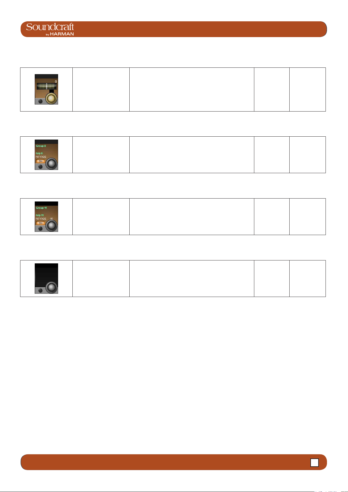
®
Vi3000 USER MANUAL
6.5.4: INPUT CHANNEL > BUSSES
Stereo Aux
Send Balance Field / Group: Aux n Range Low Range High
The Stereo symbol above the encoder shows that this
Adjust balance of the
numbered stereo aux
send.
aux send has been combined with its numerical neighbour to create a stereo aux send. The 'neighbour' aux
send space will either be blank or show a balance control, depending on the busses' 'channel pan' status. If
the aux has been set to follow the input channel panning,
there will be no balance control.
30L 30R
Group Buss
Routing Field / Group: Group n Inactive Active
Route the input channel
signal to the numbered
group bus.
The corresponding group assign bar in the bus touch
screen area is extended and highlighted in blue when the
numbered groups bus routing is enabled for this channel.
Off On
Stereo Group
Buss Routing Field / Group: Group n Inactive Active
Route the input channel
signal to the numbered
stereo group buss.
The Stereo symbol above the encoder indicates that
this group has been paired with its neighbour to create
a stereo group buss that follows channel panning. The
neighbouring group display will be blank.
Off On
Buss 'Blank' Field / Group: Inactive Active
Shows this buss has
been assigned as a
Matrix buss.
- -
6.5.4 6.5.4: INPUT CHANNEL > VISTONICS>BUSSES
Page 65

Vi3000 USER MANUAL
®
®
Vi3000 USER MANUAL
6.5.5: INPUT CHANNEL > OUTS
Input Touch Screen Audio Blocks - Panning, Insert, Direct Out, Delay.
This page contains the output functions of the input channel including the panning, the routing to the mix masters, and
the insert point and the direct out paramters. The Pan can work in LR or in LCR mode. In LCR mode an additional
width function is available.
Panning Field / Group: PAN Range Low Range High
Adjusts panning to the
Master L, R, and C
busses, depending on
pan mode chosen.
Panning On Field / Group: PAN Inactive Active
Activate or deactivate
the panning controls.
If the channel is paired, the balance can be adjusted. If
the Pan {MODE} is set to LCR, an additional WIDTH eld
becomes available.
If PAN is set to OFF, then the level to all master busses
is the same as if pan controls are 'middled'. That is -3dB
for mono channel panning and 0dB for paired channel
balance. If PAN is set to ON then the level to the master
busses varies between 0dB and -innity. For balance
that becomes +3dB to -innity.
30L 30R
Off On
6.5.5 6.5.5: INPUT CHANNEL > OUTS (PAN, INSERT, DIR, DELAY)
Page 66

®
Vi3000 USER MANUAL
6.5.5: INPUT CHANNEL > OUTS
LR On
Centre On
Field / Group: MASTER LR Inactive Active
Routes the channel
signal to the Left and
Right masters.
Field / Group: MASTER C Inactive Active
Routes the channel
signal to the Centre
master bus.
Off On
Off On
Panning Mode Field / Group: MODE Range Low Range High
Set either LR or LCR
Mode.
In LR Mode only Pan is available, though routing to the
C master bus is still possible. With LCR mode enabled,
the width parameter becomes available.
LR LCR
Insert Patch Field / Group: INSERT Active
Insert points provide a send and return path that inter-
rupts the channel signal ow.
In any Insert Select page, all available insert points can
be patched to physical I/O by touching the on-screen
Select and assign physical I/O for the insert
send and return.
(SETUP) button. You can return to insert assignment
by touching the (SETUP) button again. In Insert SETUP
mode you can choose send and retun I/O from any of
the available physical inputs and outputs, and you can
pair inserts.
You can assign input channel inserts to any unused
insert point or to an available internal FX unit. If you try
to select an insert point that has already been assigned,
you will be offered the option to ‘steal’ that insert.
Close Patch-
ing Screen.
Open Patch-
ing screen.
Insert Point Field / Group: POINT
Select the point in the
input channel's signal
path for the insert point
'tap'.
Options are post-HPF/Pre-processing, post-processing/
pre-fader, or post-fader.
6.5.5 6.5.5: INPUT CHANNEL > OUTS (PAN, INSERT, DIR, DELAY)
Page 67

Vi3000 USER MANUAL
®
®
Vi3000 USER MANUAL
6.5.5: INPUT CHANNEL > OUTS
Insert Trim Field / Group: TRIM Range Low Range High
Adjust the actual send
signal level.
Insert On Field / Group: TRIM Inactive Active
Activate the insert point. Off On
Direct Output
On Field / Group: Inactive Active
Activate the Direct
Output for this input
channel.
Off On
Direct Output
Gain Field / Group: Range Low Range High
Adjust the gain of the
channel's Direct Output.
-90dB +10dB
Direct Output
Point Field / Group:
Select the point in the
Direct Output
Patch
input channel's signal
path for the Direct Output 'tap'.
Field / Group: DIRECT
OUT Inactive Active
Options are pre HPF, post-HPF/Pre-processing,
post-processing/pre-fader, or post-fader.
Select and assign physical I/O for the direct
output.
Opens a patching screen in the corresponding Vistonics
touch screen area.
Close Patch
Screen
Open Patch
6.5.5 6.5.5: INPUT CHANNEL > OUTS (PAN, INSERT, DIR, DELAY)
Screen
Page 68

Vi3000 USER MANUAL
®
7.0: OUTPUTS
Outputs
Auxilliaries, Groups, and LCR Mix busses
7.0 7.0: OUTPUTS
Page 69

Vi3000 USER MANUAL
®
®
Vi3000 USER MANUAL
7.0: OUTPUTS
4.3: INPUT CHANNEL > DYNAMICS
There are 24 congurable output busses on the Vi 3000, plus the Master Left, right, and Center (LRC) busses. You
can choose to assign any of the 24 busses as mono OR stereo Auxilliaries or Groups with full processing. You can
create stereo busses with no reduction in the total number of available busses (24 busses are available regardless of
whether they are mono or stereo).
Up to 16 busses can be congured as mono or stereo Matrix (MTX) outputs with full processing, each with up to 24
congurable sources (including busses) - effectively creating up to 16 24-source mixes. Most of the references in this
chapter refer to the Auxilliary and Group assignments. For the full Matrix system reference please see the Matrix reference chapter 9.
In normal operation (Output Fader Pages A, B, C, and User views) bus master output controls are mapped to the
VST encoders in the Master Bay Vistonics screen over two pages. Use the [PAGE A] and [PAGE B] buttons to switch
between those pages.
4.3 INPUT CHANNEL > De Esser
7.0 7.0: OUTPUTS
Page 70

Vi3000 USER MANUAL
®
7.1: OUTPUTS > LCR MASTERS
Outpus: LCR Mix Master Busses
LRC Mix Outputs
The LRC Bus Master faders are located in the MASTERS section in the console Master Bay. These are dedicated
faders and controls, and are never used for anything else.
To access the LRC Bus mastering page, simply press the MASTERS [SEL] button. The processing page will appear
on the MasterBay Vistonics touch screen area.
The LRC Master busses can have their Parametric and/or Graphic Equaliser sections linked for easier adjustment.
See below for more detail.
7.1 7.1: OUTPUTS > LCR MASTERS
Page 71

Vi3000 USER MANUAL
®
®
Vi3000 USER MANUAL
7.1: OUTPUTS > LCR MASTERS
4.3: INPUT CHANNEL > DYNAMICS
Isolate Active
Isolate the LRC Masters
from snapshot recall
or Show Recall (with
global ltering acive).
See the Snapshots / Global Filtering reference for more
detail.
Channel
isolated
On Inactive Active
Bus On/Off (Mute). Off (Muted) On
LCR Select Active0
LCR Fader
L/C/R Link
setup
Access EQ
Access the LCR Master
Busses processing
page.
Control the output levels
of the LRC Masters
Set up LRC Master bus
EQ and GEQ linking.
Gives access to the procesing blocks in the Master LRC
outputs via the touch screen area of the Master Bay
Vistonics.
The output levels of the LRC Master outputs are always
controlled by their dedicated faders. Those faders are
never used for anything else.
Left and Right busses can be linked, or the Centre bus
can be added to the linked L and R so that all three
busses can be adjusted together. It is not possible to link
Left and Centre or Right and Centre. The defualt state,
loaded with Default Show Files, is for LINK to be set to
ON for LCR busses, both EQ and GEQ.
GEQ In
Adjust the parameteric
EQ for this Master.
4.3 INPUT CHANNEL > De Esser
7.1 7.1: OUTPUTS > LCR MASTERS
The output bus parametrc EQ is the same is used for the
input channel EQ. Please see the input channel reference for more detail.
Page 72

®
Access L/C/R
GEQ
Vi3000 USER MANUAL
7.1: OUTPUTS > LCR MASTERS
L/C/R Dynamics
L/C/R Insert/
Delay etc
Maps the BSS Graphic
equaliser for this block
to the console faders.
Access the L/C/R bus
dynamics.
The controls for the
Insert/Delay section are
similar to those of the
input channels.
See the BSS Graphics Equaliser reference later in this
chapter for more Detail.
The controls are identical to those of the input channels,
except there are no Gate or De-Esser modes available
for output busses.
Extra functions unique to the insert section of the output
channels are Low Cut Filter, Phase, and Delay. However,
thse are the same as those in the Input section of the
input channels.
7.1 7.1: OUTPUTS > LCR MASTERS
Page 73

Vi3000 USER MANUAL
®
®
Vi3000 USER MANUAL
7.2: OUTPUTS > BUS CONFIGURATION
4.3: INPUT CHANNEL > DYNAMICS
Outpus: Bus Conguration
To congure the console busses and map the bus masters to the console input channel strips, you simply press the
[ALL BUSS] button in the Input Fader Pages controls or assign a bank of eight bus masters to input bay 3 (right hand
bay) by touching the relevant metering group in the Master Bay touch screen. You then patch physical outputs and
name the busses by touching the Panning/Insert processing block in the touchscreen area and presing the {BUS OUT}
and {OUT LABEL} buttons in the VST area.
You can name the output busses and assign the physical output by touching the nal PAN/INSERT/DELAY processing
block and presing the {BUS OUT} and {OUT LABEL} buttons in the VST area.
4.3 INPUT CHANNEL > De Esser
7.2 7.2: OUTPUTS > BUS CONFIGURATION
Page 74

®
Bus Type
Vi3000 USER MANUAL
7.2: OUTPUTS > BUS CONFIGURATION
Pan Follows
Channel
Bus Format
Set the Bus Type for
this Bus.
Set 'Pan follows channel' for a stereo bus.
Choose a format (mono
or stereo) for the bus.
Choose from AUX, GRP or MTX with the encoder. If Aux
is selected and if the format eld is set to stereo then the
{CHPAN} eld is enabled.
Set this so the panning into a stereo auxilliary follows the
channel panning rather than the Aux panning.
For Stereo Auxilliary busses, the CHPAN option will
become available.
7.2 7.2: OUTPUTS > BUS CONFIGURATION
Page 75

Vi3000 USER MANUAL
®
®
Vi3000 USER MANUAL
7.3: OUTPUTS > BUS MASTER CONTROL
4.3: INPUT CHANNEL > DYNAMICS
Outpus: Bus Master Control
Outputs Controls
There are four ways of controlling the console’s bus masters and two ways of acessing the output bus processing and
parameters:
Master Bay VST Encoders
Bus master levels are available on the VST Encoders in the Master Bay, with groups of bus masters selected via the
[Page A] and [Page B] Vistonics control buttons. The [TB ASN] (Talkback Assign), [ON/OFF], and [SOLO/SEL] Vistonics control buttons select the VST button function.
4.3 INPUT CHANNEL > De Esser
7.3 7.3: OUTPUTS > BUS MASTER CONTROL
Page 76

Vi3000 USER MANUAL
®
7.3: OUTPUTS > BUS MASTER CONTROL
Master Bay output channel strips
Bus masters levels can be mapped to the eight Master Bay faders and associated channel strip controls by selecting
Master Bay FADER PAGES buttons [A] (Busses 1-8), [B] (Busses 9-16), and [C] (Busses 17-24).
All Busses Mode
If the All Busses mode is active, achieved by pressing the [ALL BUSS] button in the Master Bay INPUT FADER PAGES controls, the input strips on all of the input bays will be switched to control the 24 output busses and the faders will
control the bus master output levels.
Third Input Bay - Fast-Select
By touching any of the channel metering areas in the Master Bay touch screen area you assign that bank of eight to
the third input bay. Three banks of eight outputs are located on the top row on the Master Bay touch screen.
Bus Parameter Control
With the console in All Busses mode, the console’s Vistonics screens give direct touch access to the processing
chains of all 24 output buss channel strips.
Alternatively, with the Master Bay Vistonics button function set to [SOLO/SEL], pushing any bus master chanel strip
[SOLO/SEL] button will display that bus output’s processing chain in the Master Bay touch screen area.
In both cases, selecting a processing block will bring that block’s parameters up on the VST area of the Vistonics
screen.
7.3 7.3: OUTPUTS > BUS MASTER CONTROL
Page 77

Vi3000 USER MANUAL
®
®
Vi3000 USER MANUAL
7.3.1: OUTPUTS > MASTERS > VISTONICS
4.3: INPUT CHANNEL > DYNAMICS
Outpus: Master Bay Vistonics
With the Bus Master Controls in the VST elds of the Master Bay, a number of primary functions are available. Use the
Master Bay VISTONICS button group to control which functions and which masters are available.
Talkback
Assign Mode
Assign the {TB ASSN}
function to the bus masters VST buttons.
On/Off Mode
Assign the {ON} function to the bus masters
VST buttons.
Solo/Sel Mode
Enable solo/Select
Mode
See the Talkback and Oscillator chapter for more information.
Assigns the {SOLO} function to the bus masters VST
buttons and let the Bus channel strip [SOLO/SEL]
buttons access the bus parameters via the Master Bay
touch screen.
4.3 INPUT CHANNEL > De Esser
7.3.1 7.3.1: OUTPUTS > MASTERS > VISTONICS
Page 78

®
Masters Bank
Pages
Bus Level
Bus Solo
Switch between banks
of bus masters in the
Master Bay Vistonics
VST area.
Control the level of the
bus output.
Vi3000 USER MANUAL
7.3.1: OUTPUTS > MASTERS > VISTONICS
Bus ON
Talkback
Assign
Solo this bus output. See the Solo system chapter for more information.
Enable / Disable (Mute)
this Bus
Assign this bus to the
Talkback system.
See the Talkback and Oscillator chapter for more information.
7.3.1 7.3.1: OUTPUTS > MASTERS > VISTONICS
Page 79

Vi3000 USER MANUAL
®
®
Vi3000 USER MANUAL
7.3.2: OUTPUTS > MASTERS > CHANNEL
4.3: INPUT CHANNEL > DYNAMICS
Outpus: Master Channel Strip
The MasterBay chanel strips are for output Bus and VCA control, determined by the Master Bay Fader Pages selectors. The [VCA] button maps VCA masters 1-8 to the Master bay faders. Buttons [A] through [C] map busses 1-24 to
the Master Bay channel strips in groups of eight. Buttons [D] maps VCA masters 9-16 to the eight master bay faders. For more information on VCAs, please see the Mute Groups & VCAs reference section 9. However, using the
[ALL-BUSSES] mode and Master Bay meter selection input channel strips become bus master strips.
4.3 INPUT CHANNEL > De Esser
7.3.2 7.3.2: OUTPUTS > MASTERS > CHANNEL
Page 80

®
ISO: Isolate
Bus
Mute Safe LED
Isolate this bus from
snapshot recall and
Show recall (when
Global Filtering is
active)
Vi3000 USER MANUAL
See the Snapshot and Global Filtering chapter for more
information.
7.3.2: OUTPUTS > MASTERS > CHANNEL
Bus Fader
FaderGlow
Bus MUTE/VCA
Display
Indicate when Mute
Safe is active for this
bus.
Control the the bus
master output level.
The channel fader is
colour-coded depending
on its function.
When the Mute Safe system is enabled (in Monitoring
section [SETUP]), then the channel strip SOLO/SEL
button activates the Mute Safe status for that channel.
Input channel levels are not colour-coded. The other
FaderGlow colours are Aux Sends: ORANGE; Groups:
GREEN; Matrix Contribution: CYAN; VCA Master 1-8:
BLUE; VCA Master 9-16: PINK.
Shows mute group and
VCA group assignment
for this channel.
Bus SOLO/SEL
If a touch-panel screen is open for the for another chan-
Defaults to adding the
a SOLO enable for the
channel.
nel in the same bay, the [SOLO/SEL] button moves the
touch screen to this channel. The button has other functions in other console modes such as selecting channel
for a Copy or Paste edit function. Other functions for
the [SOLO/SEL] button are detailed in the appropriate
reference sections.
7.3.2 7.3.2: OUTPUTS > MASTERS > CHANNEL
Page 81

Vi3000 USER MANUAL
®
®
Vi3000 USER MANUAL
7.3.3: OUTPUTS > MASTERS > PROCESS
4.3: INPUT CHANNEL > DYNAMICS
Outpus: Master Bus Processing Chain
The bus output processing chain has a parametric EQ block, a BSS Graphic Equaliser block (GEQ), a dynamics block,
and a Pan/Insert block. You can also label the bus, assign a physical output, and set a delay inside the Pan/Insert
block.
4.3 INPUT CHANNEL > De Esser
7.3.3 7.3.3: OUTPUTS > MASTERS > PROCESS
Page 82

®
Bus Channel
Strip EQ
Vi3000 USER MANUAL
7.3.3: OUTPUTS > MASTERS > PROCESS
Bus Channel
Strip GEQ
Bus Channel
Strip Dynamics
Bus Channel
Strip Insert,
Delay
Adjust the parameteric
EQ for this Master.
Maps the BSS Graphic
equaliser for this block
to the console faders.
The controls are identical to those of the input
channels, except there
are no Gate or De-Esser modes available for
output busses.
The output bus parametrc EQ is the same is used for the
input channel EQ. Please see the input channel reference for more detail.
See the BSS Graphics Equaliser reference later in this
chapter for more Detail.
The controls for the
insert section are similar
to those of the input
channels.
Patch and name the buss, as well as control panning
insert conguration, delay, and more. Extra functions
unique to the insert section of the output channels are
Low Cut Filter, Phase, and Delay. However, thse are the
same as those in the Input section of the input channels.
7.3.3 7.3.3: OUTPUTS > MASTERS > PROCESS
Page 83

4.3: INPUT CHANNEL > DYNAMICS
®
®
Vi3000 USER MANUAL
Vi3000 USER MANUAL
7.4: OUTPUTS > GRAPHIC EQ
Graphic Equalisers (GEQ)
The console has a total of 27 high-quality BSS Graphic Equalisers (GEQ) - one for each of the 24 assignable Busses,
and one for each of the LCR Master outputs. The GEQs are all 30-Band EQs with an adjustable bandwdith control.
To access a GEQ, simply select a GEQ processing block from an output’s touch-screen parameter display.
Bus parameter displays can be accessed either by entering All Busses mode with the [ALLBUSS] button and selecting
the GEQ block from the corresponding channel’s touch screen area, or by selecting a bus [SOLO/SEL] button while
the Master Bay Vistonics button assign is set to Solo/Select. For more information see the Bus Output reference.
When a GEQ is selected, Bandwidth, Flatten, and In controls are mapped to the right-most VST controls, and the
Graphic EQ bands are mapped to the console faders. There are two GEQ control modes. The Large GEQ mode maps
all 30 bands accross the consoles faders. The Small GEQ mode mode maps eight GEQ bands to the Master Bay faders - scrollable with the Output Fader Page buttons [A] to [E]. The GEW Control mode is set in the Main Menu Settings
Tab.
4.3 INPUT CHANNEL > De Esser
7.4 7.4: OUTPUTS > GRAPHIC EQ
Page 84

Vi3000 USER MANUAL
®
®
Vi3000 USER MANUAL
7.4: OUTPUTS > GRAPHIC EQ
4.3: INPUT CHANNEL > DYNAMICS
Bandwidth Range Low Range High
Adjust the bandwidth of
the 30 GEQ bands.
The Bandwidth units can either be Q or Octaves,
depending on the {EQ UNIT} setting in the Main Menu
(Settings Tab).
0.24Oct 0.36Oct
Flatten All Active
Flatten levels of all
bands of the currently
active GEQ to 0dB.
All GEQ
bands 0dB
GEQ In Inactive Active
Activate or deactivate
the currently selected
GEQ.
GEQ Out GEQ In
Graphic EQ
Fader Range Low Range High
Adjust the level of the
corresponding band.
The FaderGlow colour for a GEQ band is red. The centre
frequency of the band is shown in the channel label
display.
-12dB +12dB
GEQ Fader On
Button Active
Indicates which GEQ
bands are non-zero,
and attens bands.
When you adjust the level of a GEQ band, the corresponding [ON] button is highlighted in red. A subsequent
press of the [ON] button will atten/null the band and turn
the [ON] light off.
Band level
0dB
4.3 INPUT CHANNEL > De Esser
7.4 7.4: OUTPUTS > GRAPHIC EQ
Page 85

Vi3000 USER MANUAL
®
8.0: MATRIX
Monitoring Matrix
Instead of a simple Output matrix, the console has a built-in, freely-congurable matrix that can have up to 16 Outputs
(mono or stereo) with full processing including parametric EQ, dynamics, delay, and graphic EQ. Each matrix output is
a mix of up to 24 congurable sources that can be signals from busses, channel direct outputs, or inputs directly from
the patching system.
The sources for each matrix mix can be individually patched, so the matrix can be utilized as 16 different mixers, each
with up to 24 inputs, with output processing.
In order to use a matrix, the output bus must rst be conggured as a matrix output. This can be done easily either via
All-Busses Mode (press the [All BUSSES] button in the Input Fader Pages section) or by touching the relevant meter
group in the Master Bay touch screen. In this case, the buss masters and assignments will be mapped to the right-
hand input bay.
Matrix Control
To map matrix contributions to the input bays, rst endsure that the [ALL BUSSES] key is NOT selected, then Press
the [SOLO/SEL] on a matrix master. All the input bays will change to the matrix contributions view and Faderglow™
illuminates with the matrix colour (cyan).
Press the Matrix source ‘+’ Vistonics button in one of the input screens above the fader you wish to use for the source. This opens
a patching screen that allows the source to be chosen from the categories on the right side of the screen: MADI, Stagebox, Local,
Direct Out or Bus Out.
Once the source is selected, its level to the matrix bus out will be controlled by the channel fader and [ON] button. With some types
of source (Direct and Bus Out) is is possible to choose the point in the signal path of the source channel or bus from where the feed
to the Matrix bus will be taken.
8.0 8.0: MATRIX
Page 86

®
Matrix Source
®
ON
Matrix Source
Fader
Matrix Source
Solo/Sel
Turn on (or off) the
corresponding matrix
source.
Adjust the level of this
source as a contribution
to the matrix mix.
4.3: INPUT CHANNEL > DYNAMICS
Vi3000 USER MANUAL
Vi3000 USER MANUAL
8.0: MATRIX
Matrix Pan Encoder
Matrix Source
Source
Cancels the Matrix
mapping and returns
channels to normal
operations.
Pan control for stereo
Matrix sources.
Choose a source for
this matrix input.
If the Matrix bus is stereo, the Pan control will appear
above each Matrix Source fader allowing the selected
source to be positioned within the stereo image of the
Matrix bus. If the Matrix is mono, this control will have no
function.
The button opens up a patch selection screen with all
available matrix sources, including output busses, physical console inputs, and input channel direct outs.
Matrix X Point
Select the point/tap
where the selected
matrix source is taken
from. For example, se-
lecting a buss master as
a matrix source offers
the choice of pre-fade,
post-fader, or post-ON.
4.3 INPUT CHANNEL > De Esser
8.0 8.0: MATRIX
Page 87

Vi3000 USER MANUAL
®
9.0: MUTE & VCA GROUPS
Mute & VCA Groups
The console supports up to 4 mute Groups (MG) and 16 primary VCA masters that can include both input and output
channels.
There is a secondary level of VCA functionality, most useful for monitor engineers, which allows the user to assign up
to 16 VCA masters to each auxilliary mix when the auxilliaries are controlled for the channel faders. This means there
are 25 possible sets of 16 VCA groups. A more detailed reference for this functionality is included later in the this chapter (section 9.3).
Each input and output strip has a VCA/mute group display next to its fader made up of eight LED indicators. These
show which mute and VCA groups each channel belongs to in three modes: mute groups 1-4, VCAs 1-8, and VCAs
9-16. The mode selection for the indicators is selected in the DISPLAY section of the MUTE & VCA GROUPS buttons
located on the left side of the Master Bay fader panel.
9.0 9.0: MUTE & VCA GROUPS
Page 88

Vi3000 USER MANUAL
®
®
Vi3000 USER MANUAL
9.1: MUTE & VCA GRPS > MUTE GROUPS
4.3: INPUT CHANNEL > DYNAMICS
Mute Groups Operation
There are four console mute groups, activated with the [1], [2], [3], and [4] buttons in the MUTE & VCA GROUPS button group. Both input and output channels can be assigned to mute groups.
When a channel mute is activated by a mute group, the channel’s ON button glows red.
Mute group assignment is started by pressing the MUTE & VCA GROUPS [SETUP] button (see below).
Mute Setup Inactive Active
Press the MUTE & VCA
GROUPS [SETUP]
button, then chose a
Mute Group button to
congure that group.
Mute Group 'n' Inactive Active
Press to activate / select
a Mute Group.
The [SETUP] button will glow blue when pressed. The
chosen mute group master button - [1], [2], [3], or [4]
- will glow red when you select that group. Press the
[SOLO/SEL] key of any channels (input and/or outputs)
to be assigned to the selected mute group, then press
[SETUP] again to exit the conguration mode.
In normal use, the mute groups selectors will activate
the chosen mute group (mute those channels). In setup
mode they select a mute group to be set up.
Normal
Normal
Mute Setup
Mode
Mute Group
Selected
4.3 INPUT CHANNEL > De Esser
9.1 9.1: MUTE & VCA GRPS > MUTE GROUPS
Page 89

Vi3000 USER MANUAL
®
9.2 MUTE & VCA GRPS > VCA GROUPS
VCA Group Operation
VCA Groups conguration is started by pressing the MUTE & VCA GROUPS [SETUP] button. When you press a VCA
Master [SOLO/SEL] button you can assign channels to that VCA group with their individual [SOLO/SEL] buttons, and
also access VCA group options - including labelling - in the Master Bay Vistonics. See below for more information.
You can select EITHER output chanels OR input channels to be part of a normal VCA group.
In order to assign VCAs, the VCA masters [SOLO/SEL] buttons have to be made available by selecting the appropriate Master Bay Fader Pages layer - [VCA] for VCA masters 1-8, or [E] for VCA masters 9-16.
VCA Master level at setup
The assignment of VCAs should be done with the channel or group faders and the VCA master, to which assignment
is being made, being at or near a nominal operating level. That is, don’t assign a VCA master to a channel or group if
the VCA master is at -40dB while the channel or group is at 0dB. There are 0dB buttons for VCA masters avilable in
VCA group conguration mode.
VCA and 'E'
Buttons Active
The [VCA] button maps VCA masters 1-8 to the eight
Fader Pages buttons for
mapping VCAs to the
Master Bay faders.
Master Bay faders. The [E] button maps VCA masters
9-16 to the eight Master Bay faders.
VCA Masters 1-16 can be assigned to any Output Fader
page from A to E, along with Bus Output faders using the
User Dened fader page setup. The VCA page cannot
be remapped and always contains VCA 1-8.
Select VCA
Range
VCA Masters
[ON] Buttons Inactive Active
If a channel that was previously on is turned off by the
Master On/Off button for
all of the VCA's member
channels.
action of a VCA Master [ON]/Off button, the channel’s
[ON] button will illuminate in red to distinguish this condition from a manually 'off' channel.
The VCA Master On/Off switch itself has only 2 states,
and always illuminates red when off, and green when on.
All VCA
Members
OFF (muted)
All VCA Mem-
bers ON
VCA Group
Fader Low Range
• When a VCA master fader is moved, the contributing
channel fader levels remain unchanged.
• If a channel is assigned to more than one VCA Group,
An offset dB level for
all channels that are
members of the VCA
Group.
the resultant offset applied to the channel is calculated
as the arithmetic sum of the dB values of each VCA
Master.
• Any VCA master fader reaching –innity dB (fader at
lowet position) will set all member channels to –innity
dB, regardless of other Master fader settings.
• The maximum gain applied to a member channel as the
result of the channel fader setting plus offsets from VCA
Master faders is limited to +10dB.
-innity
VCA Master
Solo/Sel Inactive Active
Depending on the setting of the AUTO button in the
A master Solo button for
all of the VCA's member
channels.
Monitor Setup page (SOLO section), activating a VCA
Solo will result in PFL (if the group only has one member
channel) or AFL (if the group has more than one member
channel).
Otherwise the VCA solo will follow the setting of the PFL/
AFL switch in the Monitor Setup page.
Normal Soloed
9.2 9.2: MUTE & VCA GRPS > VCA GROUPS
Page 90

Vi3000 USER MANUAL
®
®
Vi3000 USER MANUAL
9.2 MUTE & VCA GRPS > VCA GROUPS
4.3: INPUT CHANNEL > DYNAMICS
VCA Setup Inactive Active
The [SETUP] button will glow blue when pressed. The
[SOLO/SEL] button of the chosen VCA Master will also
Press the MUTE & VCA
GROUPS [SETUP] button, then chose a VCA
[SOLO/SEL] to congure that VCA group.
glow blue. You can then press the [SOLO/SEL] buttons
on any channels you wish to make part of that VCA
group. Then either press the [SETUP] button again to
exit the conguration mode, or press another VCA Master [SOLO/SEL] button to congure a new VCA group.
During conguration of VCA groups, a number of options
become available in the Master Bay touch screen and
VST area (see below).
Normal Setup Mode
Bulk Assign
VCA
Aux VCA Mode
Bulk On/Off
Reset VCA
Masters
Label VCA
Group
Select all input channels
or no channels as members of the VCA Group.
Switch all VCA Masters
in the Master bay
between Aux VCA Mode
and Normal mode.
(See Aux VCA Mode
reference).
Set VCA Masters to
0dB.
Select the VCA Group you require by pressing its
[SOLO/Sel] button rst.
Either set the currently selected master to 0dB, or all aux
send VCA masters (see Aux VCA Mode reference).
Opens up a standard
labelling keyboard in
the Master Bay touch
screen area for labelling
the VCA master.
Hide Labelling Keyboard
Aux VCA Mode
[On]/Off
See the curently selected Aux VCA Master
on or off (see Aux VCA
Mode reference).
4.3 INPUT CHANNEL > De Esser
9.2 9.2: MUTE & VCA GRPS > VCA GROUPS
When in fader [FLW] mode and an Aux master is
selected, VCA Masters set to 'ON' will control the Aux
VCA group, not the 'normal VCA group. Aux VCA group
master faders are highlighted with white FaderGlow,
while 'normal' channel VCAs are highlighted with blue
FaderGlow.
Normal
Show Labelling Keyboard
Aux VCA
Mode Active
Page 91

Vi3000 USER MANUAL
®
9.3 MUTE & VCA GRPS > AUX VCA GROUPS
Aux VCA Groups (fader controlled)
The VCA Groups on the console are normally used to control groups of the input channel faders, for use by FOH
engineers. In this case they are used to group mono and/or stereo channels together under control of a single master
fader, for easier control during a mix.
For the Monitor mix engineer, controlling channel faders is of secondary importance to controlling Aux sends from
channels, and so the functionality of VCA Groups has been extended to control of groups of Aux sends as well as
channel faders.
Because there can be up to 24 Auxiliary sends congured on the console, this means that there are up to 24 sets of
VCA groups (each with up to 16 Group Masters), in addition to the set of main channel fader VCA groups.
VCA control of Auxes is only available by activating the Follow Output Solo [FLW] key next to the master faders. The
pair of [FLW] keys for the VST Encoder Rows will not access this function.
It is possible to control only one Aux mix via its VCA masters at any one time.
When setting up Auxilliary VCAs, it is possible to turn the Aux VCA masters mode on or off for each VCA Master, so
‘normal’ VCAs can still be available.
9.3 9.3 MUTE & VCA GRPS > AUX VCA GROUPS
Page 92

Vi3000 USER MANUAL
®
®
Vi3000 USER MANUAL
9.3 MUTE & VCA GRPS > AUX VCA GROUPS
4.3: INPUT CHANNEL > DYNAMICS
Auxilliary VCA Procedure
1) Select the Aux bus required by selecting the required master fader page [A]-[C].
2) Activate the [FLW] key next to the master faders.
3) Press the [SOLO/SEL] key under the required Aux master fader (or use the solo switches in the Master VST area).
4) Press [VCA] (for VCA 1-8) or [E](for VCA 9-16).
5) The FaderGlow for any active VCA master faders will change to white and the faders will move to show the offsets
being applied to the Aux feeds from those channels assigned to the VCAs. At this point, the VCA Master [SOLO/SEL]
keys have no function. The VCA [ON] switch controls the Aux send On/Off on the member channels.
6) To select another Aux for adjustment, press the required bank key [A]-[C], solo the required aux (or solo directly on
the VST screen), and press [VCA] or [E]. To exit, press [SOLO CLEAR] and de-select [FLW].
Note: To set up Auxilliary VCAs, press the MUTE & VCA GROUP [SETUP] button after step 4 and assign member
channels to that Aux VCA group as per the normal VCA group setup procedure (use the channel [SOLO/SEL] buttons
to choose members, then press [SETUP] to exit). Note that Aux VCA Groups have to share the same input assignments as the ‘normal’ channel VCAs.
4.3 INPUT CHANNEL > De Esser
9.3 9.3 MUTE & VCA GRPS > AUX VCA GROUPS
Page 93

Vi3000 USER MANUAL
®
10.0: MONITORING
Monitoring System
The monitoring system has three main sources - Monitor A, Monitor B, and Headphones. These are fed by a choice
of sub-sources, including Solos, LCR, Talkback return, and two user-dened stereo sources where the left and right
singals can be patched independantly
10.0 10.0: MONITORING
Page 94

4.3: INPUT CHANNEL > DYNAMICS
®
®
Vi3000 USER MANUAL
Vi3000 USER MANUAL
10.0: MONITORING
4.3 INPUT CHANNEL > De Esser
10.0 10.0: MONITORING
Page 95

Vi3000 USER MANUAL
®
10.1: MONITORING > CONTROL
Monitoring: Console Controls
The following console monitoring controls are located to the right of the master faders in the Master Bay, except for
[INPUT PRI] (Solo Input Priority), which is located with the SOLO button group on the upper section, to the right of the
Master Bay.
There are three main monitoring outputs - A, B, and headphones. Monitor A is an LCR output, Monitor B is an LR output, and the headphones output is LR to the headphone socket on the front of the console. You can select a variety of
sources for the monitoring outputs, including two user-denable sources, USER A and USER B, with separate left and
right assignments.
Solos can be blended with the main monitor feed for contextual solos, and an Auto function can be set to select PFL or
AFL depending on your solo selections.
Solo system control is described in the Monitoring SETUP section. The console’s Solo system logic and general use is
described in the next chapter (11).
10.1 10.1: MONITORING > CONTROL
Page 96
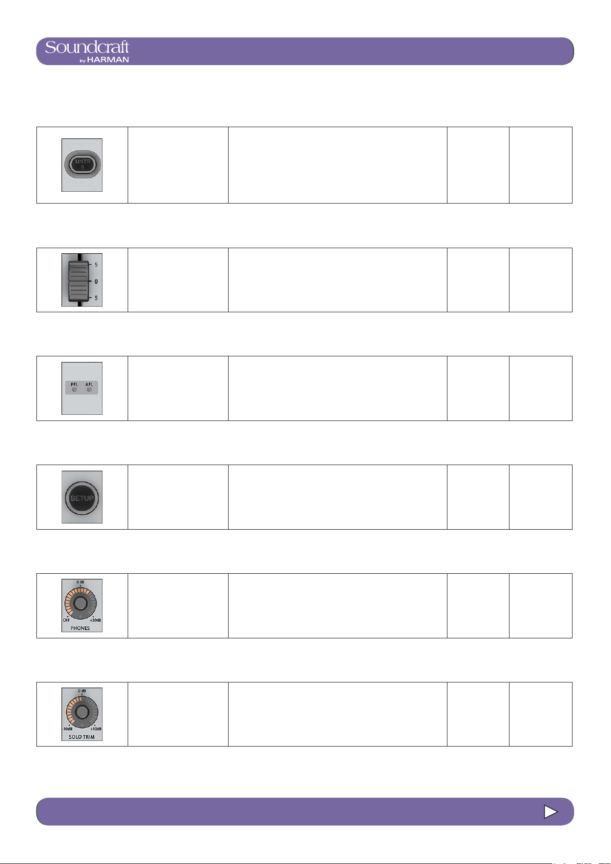
4.3: INPUT CHANNEL > DYNAMICS
®
®
Vi3000 USER MANUAL
Vi3000 USER MANUAL
10.1: MONITORING > CONTROL
MNTR B - Monitor A/B Select Inactive Active
Select either the A or
the B monitor to be
displayed on the meter,
to be controlled by
the fader, and to be
switched on and off by
the [ON] switch.
Both Monitor A and B sources are always active (respecting their individual On/Off status'). The MTR B
button changes metering and control assignment.
Monitor A Monitor B
Monitor Fader Range Low Range High
Control monitoring
volume level.
-Innty +10dB
AFL and PFL
indication
These two LEDs show if
an active solo is a PFL
or an AFL.
Monitoring
Setup Active
Display the Monitor Setup Page on the master
screen.
The [SETUP] key glows blue when it is active. SETUP Active
Headphones
Level Range Low Range High
Control the headphones
volume level.
The headphone output socket is located under the armrest at the front of the console, and is designed for headphones with impedances in the range 50-600 Ohms.
OFF +20dB
Solo Trim Range Low Range High
Trims source SOLO
Level.
4.3 INPUT CHANNEL > De Esser
10.1 10.1: MONITORING > CONTROL
This control is SOLO context sensitive. It is possible to
set a different trim for each of the 24 outputs in addition
to a global input solo trim level.
-10dB +10dB
Page 97

Vi3000 USER MANUAL
®
10.1: MONITORING > CONTROL
Solo Blend Range Low Range High
monitor_con_solo-
Blend.jpg
Adjust the background
level of the monitoring
source signal.
The level of the non-solo source adjusted from OFF to
-10dB to allow solos to be heard in the context of a mix
that has a reduced level.
OFF -10dB
Solo Input Priority Active
Allows an Output Solo to remain active, whilst an Input
monitor_con_soloIn-
Priority.jpg
Activate Input Priority
Mode
Solo is temporarily activated ‘over the top’ of it. When
the Input Solo is deactivated, the Output Solo’s audio
will return to the Solo Bus. For more detail, see the Solo
System reference chapter 11.
Input Priority
Active
10.1 10.1: MONITORING > CONTROL
Page 98

4.3: INPUT CHANNEL > DYNAMICS
®
®
Vi3000 USER MANUAL
Vi3000 USER MANUAL
10.2: MONITORING > SETUP
Monitoring Setup
All monitoring source assignments for MONITOR A, B, and HP are assigned in the monitoring setup page, as well as
monitoring delay.
Monitoring
Input Solo
Source
Choose either input
channel PFL, AFL, or
'AUTO' as the Input
Solo source.
Output solo
source
Choose either output
buss PFL or AFL as the
Output Solo Source.
The AUTO option works by selecting PFL when only
one solo is active and AFL when more than one solo is
active.
4.3 INPUT CHANNEL > De Esser
10.2 10.2: MONITORING > SETUP
Page 99

®
Solo-In-Place
Mode
Mute Safe
Mode
Activate the SOLO-INPLACE mode.
Vi3000 USER MANUAL
This is a destructive mode for use only during soundchecks or rehearsals. When a channel is soloed in SIP
mode, all other channels are muted so that only the
soloed channel is heard, in its stereo position, at the
console’s mix outputs.
10.2: MONITORING > SETUP
MON SETUP
Mode
Auto Cancel
Mode
LCR Source
Select
Enable the Mute Safe
(SIP isolation) conguration mode.
Activate the Monitor
Setup sub-page.
TBC
If (MUTE SAFE) is active the Mute safe state from the
Input channels can be toggled with the Channel’s SEL
Key. The state for a given channel is indicated by that
channel’s Mute Safe LED. NOTE: This conguration
mode is disabled when the setup page is exited.
The Monitor Setup sub-page parameters become available in the VST area of the master screen. See below for
more details.
Select the mix master
output sources for the
monitor outputs A, B,
and HP
For the Monitor A (LCR) output you can choose LCR
and/or C; for the Monitor B and Headphone outputs you
can choose LR and/or C. This selection cannot be combined with the User A or User B sources, but solo and
talkback options are concurrent.
User A / B
Source Select
Select the user-dened
output source for the
monitor outputs A, B
and HP.
Choose EITHER User A or User B as a main source
for the monitoring output. This selection cannot be
combined with the LCR, LR, or C sources, but solo and
talkback options are concurrent. Each of the monitoring
outputs has its own individual USER A / B assignment.
10.2 10.2: MONITORING > SETUP
Page 100

®
®
Input Solo Select
4.3: INPUT CHANNEL > DYNAMICS
Vi3000 USER MANUAL
Vi3000 USER MANUAL
10.2: MONITORING > SETUP
Output Solo
Select
Talkback Return Select
Monitor Follow
A
Route the Input Solo
Signal to the Monitor
A, B, and headphone
outputs.
Route the Output Solo
Signal to the Monitor
A, B, and Headphone
outputs.
Route the Talkback
Return Signal to the
Monitor A, B, and Headphone outputs.
The Input Solo signal is dened in the SOLO section of
the monitor setup screen. Each of the monitoring outputs
has its own individual IN SOLO assignment.
The Output Solo signal is dened in the SOLO section of
the monitor setup screen. Each of the monitoring outputs
has its own individual OUT SOLO assignment.
Each of the monitoring outputs has its own individual
Talkback Return assignment.
Force the Monitor B
and/or Headphone
source assignments
to be the same as the
MONITOR A assignment.
Monitor output
format
LR - left source to left monitor out and right source to
Selects one of the
stereo format options to
be the listening format
for the Monitor A, B, and
Headphone outputs.
right monitor out • RL - left source to right monitor out,
right source to left monitor out • LL - left source to left
and right monitor outputs • RR - right source to left
and right monitor outs • Mono - left and right source is
summed and fed to left and right monitor. The Centre
signal is not affected. Each of the monitoring outputs has
its own individual FORMAT selection.
Monitoring delay - Fine Range Low Range High
Fine Control of the monitoring delay time.
Zero Delay NEEDED
4.3 INPUT CHANNEL > De Esser
10.2 10.2: MONITORING > SETUP
 Loading...