


Soundcraft K3 USER GUIDE

SOUNDCRAFT
USER GUIDE

© Harman International Industries Ltd. 1995,1996
All rights reserved
Parts of the design of this product may be protected by worldwide patents.
Part No. ZM0090 Issue 3
Soundcraft is a trading division of Harman International Industries Ltd.
Information in this manual is subject to change without notice and does not represent a
commitment on the part of the vendor. Soundcraft shall not be liable for any loss or damage
whatsoever arising from the use of information or any error contained in this manual.
No part of this manual may be reproduced, stored in a retrieval system, or transmitted, in any
form or by any means, electronic, electrical, mechanical, optical, chemical, including
photocopying and recording, for any purpose without the express written permission of
Soundcraft.
It is recommended that all maintenance and service on the product should be carried out by
Soundcraft or its authorised agents. Soundcraft cannot accept any liability whatsoever for any loss
or damage caused by service, maintenance or repair by unauthorised personnel.
Harman International Industries Ltd.
Cranborne House,
Cranborne Road,
Cranborne Industrial Estate,
Potters Bar,
Herts.,
England.
EN6 3JN.
Tel: 01707 665000
Fax: 01707 660482

Table of Contents
1. Introduction 1.1
Introduction 1.2
Warranty 1.4
2. Installation 2.1
Dimensions 2.2
Precautions and Safety Instructions 2.3
Mains Installation 2.4
General Wiring Procedures 2.5
Connections 2.8
3. Block Diagrams 3.1
Standard Mono Input Module 3.2
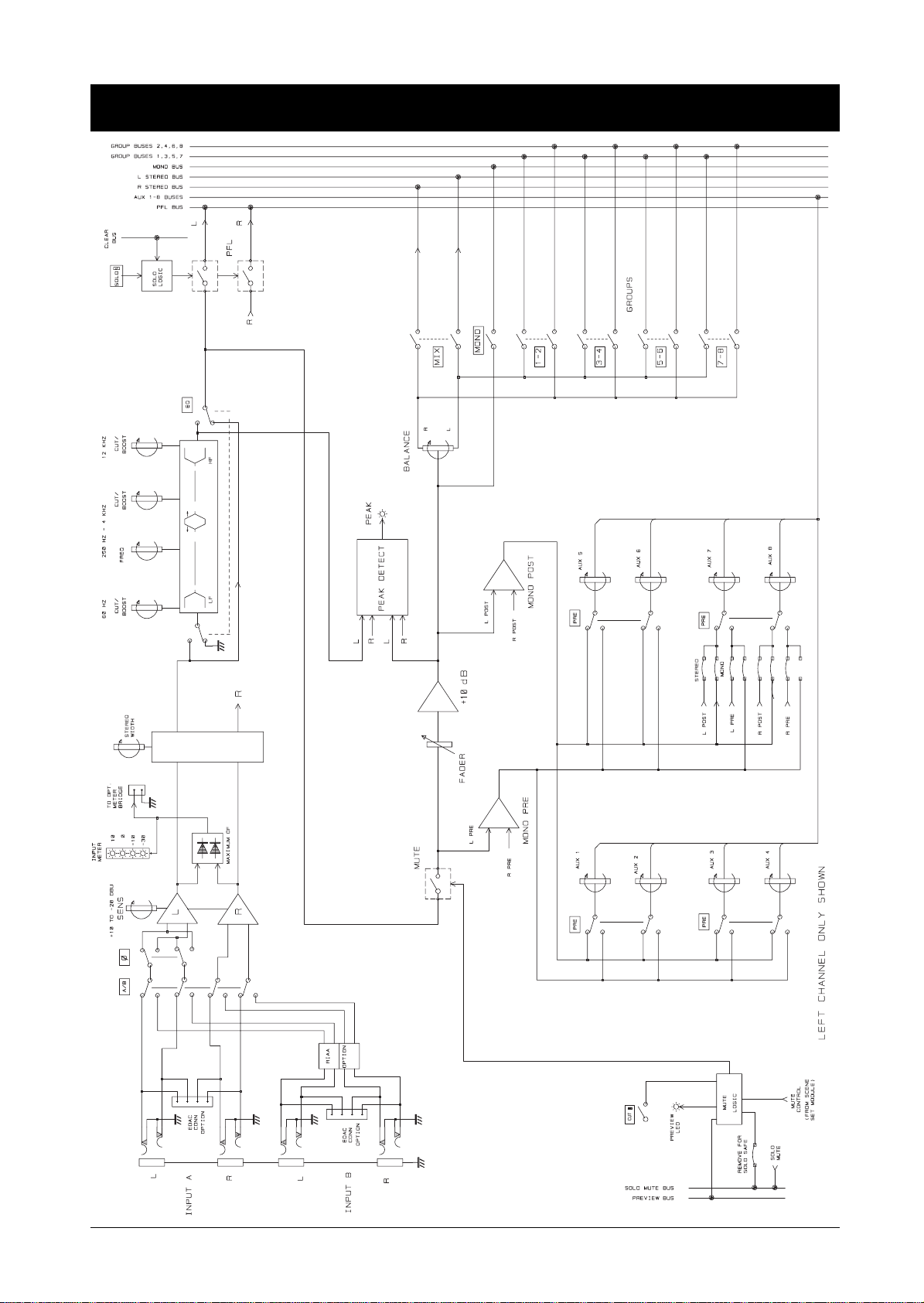
Theatre Mono Input Module 3.3
Stereo Input Module 3.4
Dual Group/EQ Output Module 3.5
Dual Group/FX Return Module 3.6
Quad Matrix Module 3.7
Master Module Sheet 1 of 3 3.8
Master Module Sheet 2 of 3 3.9
Master Module Sheet 3 of 3 (Aux Master) 3.10
4. Functional Description 4.1
Standard Mono Input Module 4.2
Theatre Mono Input Module 4.5
Stereo Input Module 4.8
Dual Group/EQ Output Module 4.11
Table of Contents i

Dual Group/FX Output Module 4.13
Quad Matrix Module 4.16
Master Module 4.18
Optional Meterbridge 4.23
Mute Scenes/Mute Groups & MIDI Module 4.25
Introduction 4.26
Mute Scenes/Mute Groups & MIDI Controller 4.27
Saving And Loading The Memory 4.28
Storing Mute Scenes 4.30
Recalling Mute Scenes 4.31
The ’All’ Scene 4.32
Introduction To The M1 - M8 Buttons 4.33
Using The M1-M8 Buttons In
Mute Groups Mode 4.34
Mute Groups Tutorial 4.35
Using The M1-M8 Buttons In
Mute Scenes Mode 4.36
Storing MIDI Parameters With Mute Scenes 4.37
Editing MIDI Parameters In Mute Scenes 4.39
Setting The Global MIDI Receive/note On/Off
Channel 4.40
Table Of MIDI Note Numbers And
Console Mutes 4.41
MIDI Implementation Chart 4.42
5. Specifications 5.1
Specifications 5.2
ii Table of Contents

1. Introduction
Introduction 1.1

Introduction
K3 Standard Console The K3 Standard Console is designed to offer value for money, and versatility that
allows the desk to perform to a high standard in a wide range of applications, from
touring rigs and medium sized band PA to fixed installations in medium sized
theatres and concert halls, conference halls and so on.
The K3 is available in five different frame sizes 16, 24, 32, 40 and 48 channels. The
choice of frames and modules means that the desk can be configured to match your
needs and budget. Good ergonomics, plus an advanced mute system and MIDI
control module, make the K3 easy for any operator to get to grips with, and exploit
its range of facilities to the full.
K3 Theatre Console The K3 Theatre is designed to offer the ultimate in control and quality from a
mid-range PA console. Based on the K3 Standard, the K3 Theatre is a modular 8-bus
console with a special mono input module featuring enhanced EQ plus refinements
such as individual routing to groups. Along with all the other K3 options, such as
choice of group modules, stereo input modules, and a slimline matrix module, the
K3 Theatre makes it easier than you ever thought possible to mix a large number of
varied mono and stereo sources in a range of sound reinforcement situations- band
FOH or FOH and monitor mixing, installed or theatre sound with a multi-speaker
rig -all with the benefits of MIDI mute control, and the K3’s exceptional ease of
use.
Module Options
The K3 Theatre is available in 16, 24, 32, 40 and 48-channel frame sizes, with an
optional VU meter overbridge.
Each frame includes:
• Either Standard or Theatre Inputs.
• 4 X Dual group/EQ or group/FX output modules.
• 1 X MIDI scene set module.
• 1 X Master module.
• 1 X Blank module
• 1 X CPS275 Power supply (48ch Theatre version needs two).
Optional fittings include:
• Quad matrix modules.
• Stereo input modules.
• VU Overbridge (Factory fitted).
• Additional CPS275 for backup supply, links to main supply with short cable.
• Dual Group/EQ or FX modules.
• Mic I/P transformer options.
1.2 Introduction

Metering A VU output overbridge is available for all K3 frames, except for 16ch. The VU
meters provide metering of the Group and Mix signals and monitor the Mono bus
output.
Additionally, the 8 VUs which normally monitor the group signals can be switched
from the front panel to read the Matrix outputs or the Aux outputs.
Power Supplies The K3 requires the CPS275 power supply unit. The CPS275 has built-in diodes in
the output. This allows a second power supply to be connected in "parallel" with
the main supply such that if any rail on either supply fails, the other CPS275 will
immediately supply the power.
Note: Although the supplies are "in parallel", they will not necessarily
share the current because the rail voltages will not be exactly equal.
When you order a spare CPS275, this comes with a short link cable which connects
from the spare supply’s "link" output into the "link" connector on the main supply.
Introduction 1.3

Warranty
1 Soundcraft is a trading division of Harman International Industries Ltd.
End User means the person who first puts the equipment into regular operation.
Dealer means the person other than Soundcraft (if any) from whom the End User
purchased the Equipment, provided such a person is authorised for this purpose
by Soundcraft or its accredited Distributor.
Equipment means the equipment supplied with this manual.
2 If within the period of twelve months from the date of delivery of the Equipment to
the End User it shall prove defective by reason only of faulty materials and/or
workmanship to such an extent that the effectiveness and/or usability thereo f is
materially affected the Equipment or the defective component should be returned
to the Dealer or to Soundcraft and subject to the following conditions the Dealer
or Soundcraft will repair or replace the defective components. Any components
replaced will become the property of Soundcraft.
3 Any Equipment or component returned will be at the risk of the End User whilst in
transit (both to and from the Dealer or Soundcraft) and postage must be prepaid.
4 This warranty shall only be available if:
a) the Equipment has been properly installed in accordance with instruc tions
contained in Soundcraft’s manual; and
b) the End User has notified Soundcraft or the Dealer within 14 days of the defect
appearing; and
c) no persons other than authorised representatives of Soundcraft or the Dealer ha ve
effected any replacement of parts maintenance adjustments or repairs to the
Equipment; and
d) the End User has used the Equipment only for such purposes as Soundcraft
recommends, with only such operating supplies as meet Soundcraft’s
specifications and otherwise in all respects in acc ordanc e Sou ndcraft’s
recommendations.
5 Defects arising as a result of the following are not covered by this Warranty: faulty
or negligent handling, chemical or electro-chemical or electrical influences,
accidental damage, Acts of God, neglect, deficiency in ele ctric al power,
air-conditioning or humidity control.
6. The benefit of this Warranty may not be assigned by the End User.
7. End Users who are consumers should note their rights under this Warranty are in
addition to and do not affect any other rights to which they may be entitled
against the seller of the Equipment.
1.4 Introduction

2. Installation
Installation 2.1
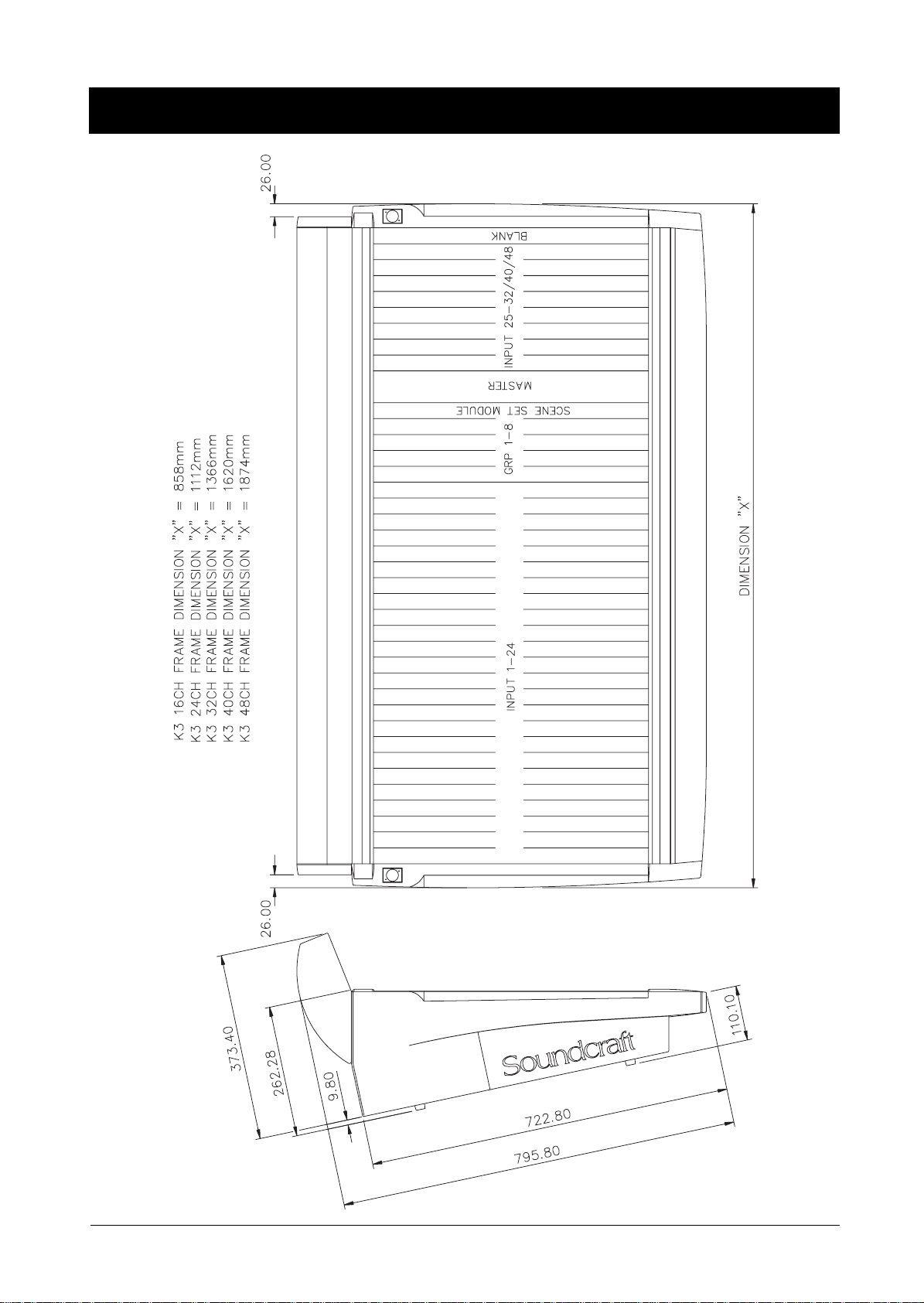
'LPHQVLRQV
2.2 Installation

Precautions and Safety Instructions
General Precautions Avoid storing or using the mixing console in conditions of excessive heat or cold, or
in positions where it is likely to be subject to vibration, dust or moisture. Do not use
any liquids to clean the fascia of the unit: a soft dry brush is ideal. Use only water
or ethyl alcohol to clean the trim and scribble strips. Other solvents may cause
damage to paint or plastic parts.
Avoid using the console close to strong sources of electromagnetic radiation (e.g.
video monitors, high-power electric cabling): this may cause degradation of the audio
quality due to induced voltages in connecting leads and chassis. For the same reason,
always site the power supply away from the unit.
Caution! In all cases, refer servicing to qualified personnel.
Handling and Transport The console is supplied in a strong carton. If it is necessary to move it any distance
after installation it is recommended that this packing is used to protect it. Be sure to
disconnect all cabling before moving. If the console is to be regularly moved we
recommend that it is installed in a foam lined flightcase. At all times avoid applying
excessive force to any knobs, switches or connectors.
Power Supplies & cables Always use the power supply and cable supplied with the mixer: the use of alternative
supplies may cause damage and voids the warranty; the extension of power cables
may result in malfunction of the mixing console.
Warning! Always switch the power supply off before connecting or
disconnecting the mixer power cable, removing or installing
modules, and servicing. In the event of an electrical storm, or large
mains voltage fluctuations, immediately switch off the PSU and
unplug from the mains.
Always ensure that you use the correct PSU for your mixer. The K3 normally requires
1 X CPS275 supply for the 16 to 40 input frames and the 48 channel input Standard.
The 48 input Theatre frame uses 2 X CPS275
On 32 to 40 plus 48 input standard frames fitted with the optional VU overbridge
an additional CPS275 is required. (CPS275 supplied with the overbridge).
Note: Each CPS275 can have a backup supply connected to it.
Signal Levels It is important to supply the correct input levels to the console, otherwise signal to
noise ratio or distortion performance may be degraded; and in extreme cases, damage
to the internal circuitry may result. Likewise, on all balanced inputs avoid sources
with large common mode DC, AC or RF voltages, as these will reduce the available
signal range on the inputs. Note that 0dBu = 0.775V RMS.
Refer to the Specifications section for details of input and output levels.
Installation 2.3

Mains Installation
Warning! Do not replace the fuse with any other type, as this could become a
The CPS275 is a linear power supply which produces the required
DC voltages used by the K3.
This unit has four nominal input voltages:
230V AC rms
115V AC rms
100V AC rms
85V AC rms.
safety hazard and will void the warranty. Use only the correct fuse
(which depends upon the nominal input voltage selected: see
CPS275 manual).
2.4 Installation

*HQHUDO:LULQJ3URFHGXUHV
To take full advantage of the excellent signal to noise ratio and low distortion of
Soundcraft consoles care must be taken to ensure that incorrect installation and
wiring does not degrade the performance of the desk. Hum, buzz, instability and
Radio Frequency interference can usually be traced to earth loops and inferior
earthing systems. In some areas, especially heavily industrial areas, the incoming
mains earth will not be adequate and a separate technical earth for all the audio
equipment must be supplied. However, check with your local electricity supply
company to ensure that safety regulations are not infringed or negated.
The successful, hum free, installation of a system requires forethought, and the
establishment of a set of ground rules, which must be consiste ntly adh ered to at all
stages of installation.
Initial Wiring
Considerations
• For optimum performance, it is essential for the earthing system to be clean
and noise free, as all signals are referenced to this earth. A ce ntral point
should be decided on for the main earth point system, and all earths should
be ‘star fed’ from this point. It is common electrical practice to ‘daisy chain’
the earths to all electrical outlets but this method is unsuitable for audio
installations. The preferred method is to run an individual earth wire from
each outlet, back to the system star point to provide a safety earth screen
reference for each piece of equipment.
A separate earth wire should also be run from each equipment rack and area ,
to the star point. This may or may not be used depending on circumstances,
but it is easier to install in the first place, than later when problems arise.
The location of the star point should be a convenient, easily accessible place,
preferably at the rear of the console or in the main equipment rack.
• Install separate ‘clean’ and ‘dirty’ mains outlets, wired individually back to
the incoming mains distribution box. Use the ‘clean’ supply for all audio
equipment and the ‘dirty’ supply for all lighting, vending machines etc.
Never mix the two systems.
• If necessary, to provide sufficient isolation from mains borne interference,
install an isolating transformer. This should be provided with a Faraday
Shield which must be connected with earth.
• Never locate the incoming mains distribution box near audio equipment,
especially tape recorders, which are very sensitive to e le c tro-magne tic fiel ds.
• Ensure that all equipment racks are connected to earth, via a separate wire
back to the star point.
• Equipment which has unbalanced inputs and outputs may need to be isolated
from the rack to prevent earth loops.
Installation 2.5

Audio Wiring
Having provided all equipment with power and earthin g connections, consideration
must be given to the method of providing audio interconnection and adequate
screening of those interconnections. This must be done in a logical sequence to avoid
problems and assist in the localisation of problem equipment.
• Connect the Monitor system to the console and chec k for any hum, buz z , or
RFI. Only when you are satisfied with the quietness of the console and the
monitor system should you proceed with the next step.
• Connect stereo tape recorders, echo and foldback sends one at a time,
checking and isolating any connection which degrades performa nce.
• Connect all other peripheral devices.
• Connect all microphone lines.
By following this sequence much time and future trouble will be saved, and the
result will be a quiet, stable system.
Shielding
Audio equipment is supplied with a variety of input and output configurations,
which must be taken into consideration when deciding where the screen connections
should be made. There are three sources of unwanted signal being impressed on the
screen, which are as follows:
• Extraneous electrostatic or electromagnetic fields.
• Noise and interference on the earth line.
• Capacitive coupling between the screen and signal wires.
To minimise the adverse affects of the unwanted coupling to the signal wires, it is
important that the screen is connected at one end only, i. e. the screen must not c arry
any signal current. Any signal on the wires within the screen will be capacitively
coupled to the screen. This current will ultimately be returned to the source of the
signal, either directly, if the screen is connected at the signal source end , or indirectly
via the earthing system, if the signal is connected at the sign al destination en d. The
indirect connection will cause an increase in high frequency cross-talk, and should
be avoided wherever possible.
Therefore, in general, always connect the shield only at the signal source end. In
high RF areas, the screen can also be co nnected to earth via a 0.01µF ca pacitor. This
will present a short circuit at RF frequencies, thus lowering the effective shield
impedance to ground. However, at low audio frequencies the reactance of the
capacitor will be sufficiently high not to cause an earth loop problem.
Points to Remember
• In all cases, use good quality twin screened audio cable. Check for
instability at the output.
• Always connect both conductors at both ends, and ensure that the screen is
only connected at one end.
• Do not disconnect the mains earth from each piece of equipment. This is
needed to provide both safety and screen returns to the system star point.
• Equipment which has balanced inputs and outputs may need to be
electrically isolated from the equipment rack and/or other equipment, to
avoid earth loops.
2.6 Installation

It is important to remember that all equipment which is connected to the ma ins is a
potential source of hum and interference and may radiate both electrostatic or
electromagnetic radiation. In addition, the mains will als o act a s a ca rrier for many
forms of RF interference generated by electric motors, air–conditioning units,
thyristor light dimmers etc. Unless the earth system is clean, a ll attempts to improve
hum noise levels will be futile. In extreme cases there will be no alternative but to
provide a completely separate and independant ‘technical earth’ to replace the
incoming ‘noisy earth’. However, always consult your local electricity supply
authority to ensure that safety regulations are not being infringed.
Installation 2.7
&RQQHFWLRQV
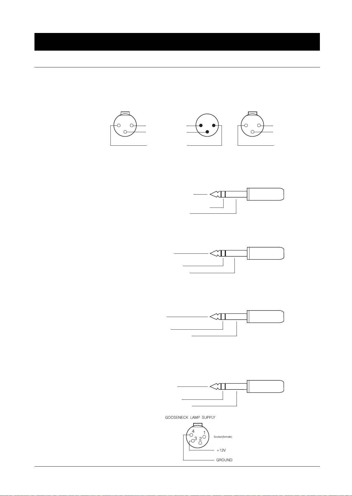
Wiring conventions
1
The K3 uses two different types of audio connector: 3-pin XLR and
⁄
" 3-pole
4
jacks. This section describes how to connect external equipment to the console.
Correctly-made cables of the proper type will ensure peak performance from your
mixer.
MICROPHONEINPUTS TALKBACKMICMONOO/P
3-pole XLR
222
111
333
Socket(female) Socket(female)
GROUND(SCREEN)
COLD (OUT OF
PHASE SIGNAL)
HOT
(IN PHASE SIGNAL)
1
/
4
Stereo Jack Plug used as balancedInput/Output:
"
Hi-Z Input, Stereo Inputs, 2-Track Inputs, Oscillator
Insert returnon Standardand Theatre Input.
OptionalInsert sends on Standardand TheatreInputs
Tip - HOT(IN PHASE SIGNAL)
Ring - COLD(OUTOF PHASE SIGNAL)
Sleeve - GROUND(SCREEN)
1
/
4
Stereo Jack Plug used as a ground compensatedoutput:
"
Aux Outputs(Insertsends on Standardand TheatreInputs)
MATRIX, TALKBACKO/P,
GROUP& MIX OUTPUTS
GROUND
GROUND
Plug(male)
SIGNAL
Tip - HOT(SIGNAL)
Ring - GROUNDSENSE
Sleeve - GROUND(SCREEN)
1
/
4
Stereo Jack Plug used as an unbalancedOutput:
"
Direct Outputs
Tip - SIGNAL
Ring - GROUND
Sleeve - GROUND(SCREEN)
1
/
4
Stereo Jack Plug used as a Stereo Output:
"
Headphones
Tip - LEFT SIGNAL
Ring - RIGHT SIGNAL
Sleeve - GROUND(SCREEN)
2.8 Installation

3. Block Diagrams
Block Diagrams 3.1
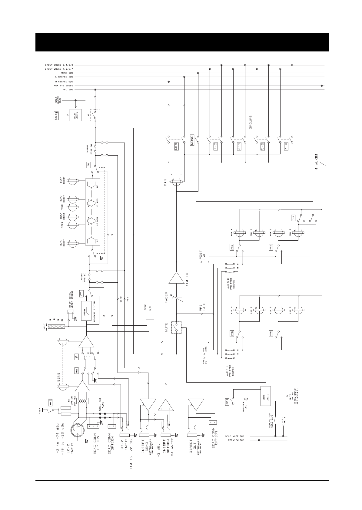
Standard Mono Input Module
3.2 Block Diagrams
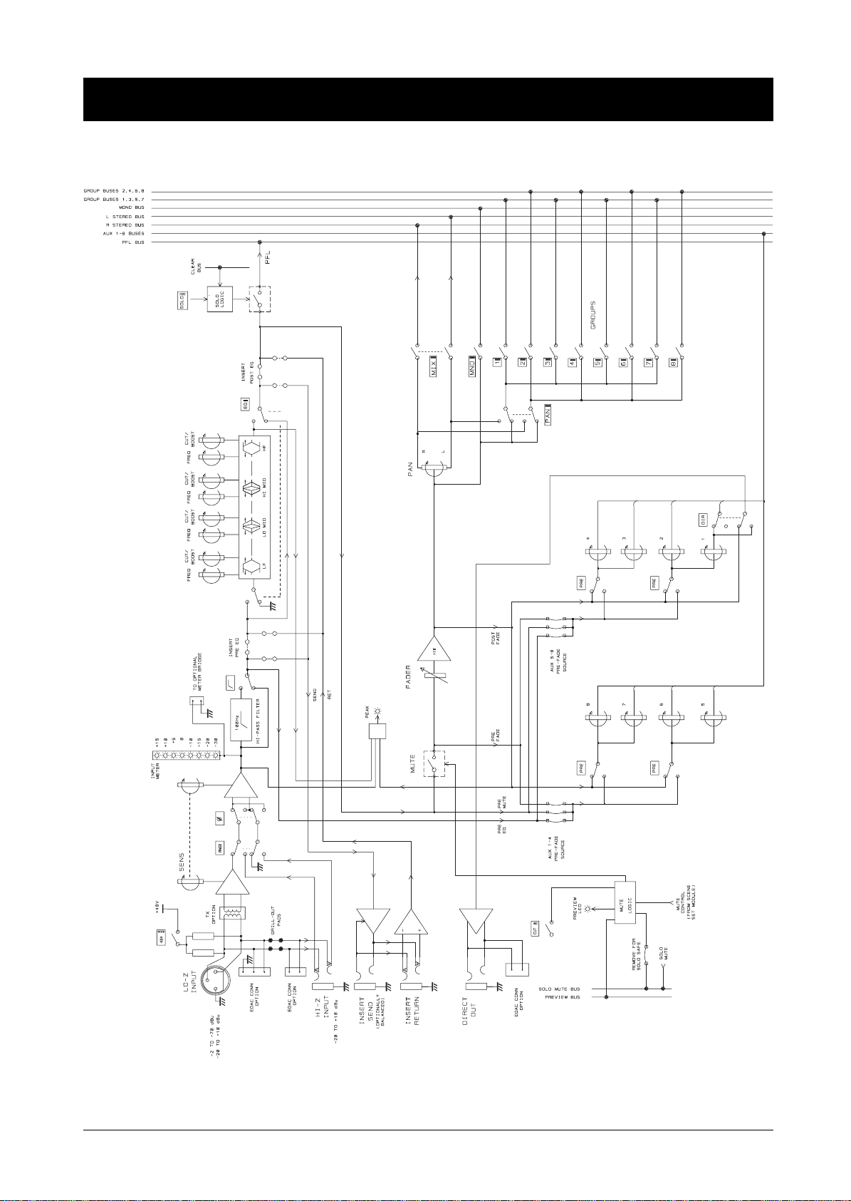
Theatre Mono Input Module
Block Diagrams 3.3
Stereo Input Module
3.4 Block Diagrams
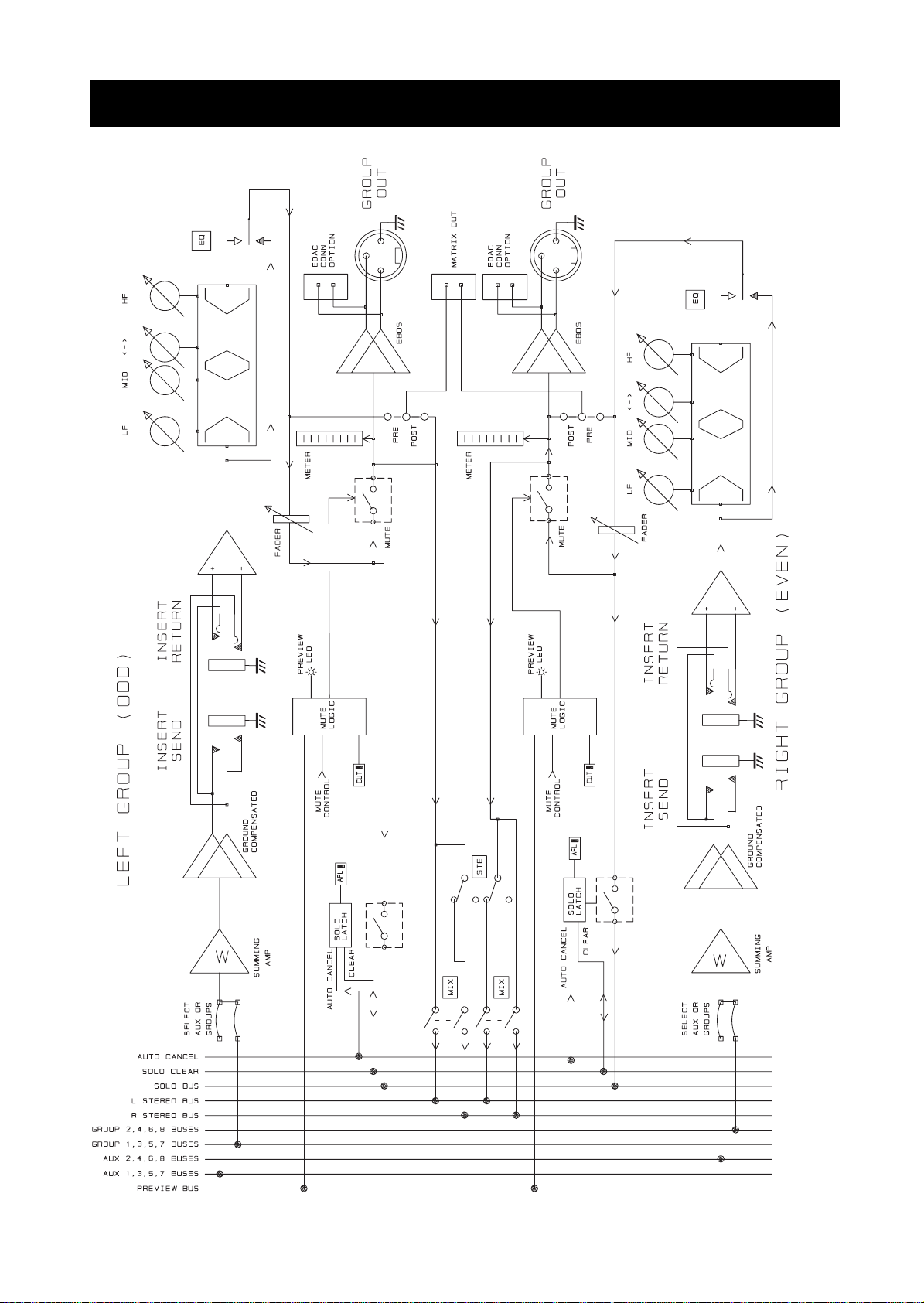
Dual Group/EQ Output Module
Block Diagrams 3.5