

Page 1

SOUNDCRAFT
USER GUIDE
Page 2

Soundcra ft Electr onics Ltd. 1994
All rights reserved
Parts of the design of t his pro duc t ma y be protec t ed by worldwid e pat en ts.
Part No. ZM0088-01
Informa ti on in this manual i s subject to change without notice and does not
represe nt a comm itm e nt on the part of the vendor . Sou ndc ra ft Elect roni c s Ltd.
shall not be liable for any loss or dama ge whatsoe ve r ari sing fr om the use of
informa ti on or any err or contained in this ma nua l.
No part of this manual may be reprod uc ed , stored in a retri eva l system , or
transm i tt ed , in an y form or by any mea ns, e lec tronic, ele c tri c al , mec ha nic a l,
optical, che mic al , inc luding photocopy ing and recor din g, for any pur pose
without the expr ess writ te n pe rm issi on of Soundcraft Elec tronics Ltd.
It is recomme nde d that all maint e nanc e and se rvi ce on the produ ct shoul d be
carried out by Soundc ra ft Elec tronics Ltd. or its authori sed age nts. Soun dc raft
Electro nics Ltd. cann ot ac cept any liab ilit y whatsoe ve r for any loss or damage
caused by servi c e, mai nten an ce or repai r by unaut hor ise d pe rsonne l .
Soundcraft Electronics Ltd.
Cranborne House
Cranborne Road
Potters Bar
Herts.
EN6 3JN
Englan d
Tel: 01707 665000
Fax: 01707 660482
Page 3

Contents
1. Introduction 1.1
System Overview 1.2
Warranty 1.3
2. Installation 2.1
Dimensions 2.2
Precautions and Safety Instructions 2.3
Mains Installation 2.4
General Wiring Procedures 2.5
Connections 2.8
3. Block Diagrams 3.1
4. Functional Description 4.1
Mono Input Channel 4.2
Stereo Input Channel 4.5
Group/Ma trix Se ction 4.8
Master Section 4.9
5. Specifications 5.1
Page 4

Page 5

1. Introduction
System Ov erv ie w
Warranty
Introduc tio n December 1994 1.1
Page 6

Introduction
The K1 is a professional, compac t, four -bus sound re in forc em en t consol e desig ned
for a wide range of appl ica ti ons in insta lle d an d porta ble sound system s.
The consol e is available in a range of free -standing frame size s or the smal lest frame
can be rack-mounted with the optional mounting brackets. The modular
construction, with input modules in blocks of four, provides ease of servicing and
config ura ti on to suit indivi dua l appl ica ti ons. All frame s inclu de a versa til e Ma ste r
section, combining group a nd main out put maste rs, monitoring, matrix outputs and
two full stere o i nput ch an ne ls.
All input m odule s inc lude a 4-ba nd EQ an d High Pass Fil ter, 6 Au xilia ry Sen ds an d
routing to 4 Sub-Groups, Stereo and Mono outputs.
Frame Sizes
Module Options
The K1 is available in 3 frame sizes:
• 8 inputs + Master
• 16 inp uts + Maste r
• 24 inp uts + Maste r
• 32 inp uts + Maste r
The 8 input fram e may be fitted wi th op tiona l mounting brac kets for installati on in
stan da rd 19 " rac ki ng.
All frames include the Master section which comprises group and main output
maste rs, monit ori ng, ma trix outputs and two full stere o inp ut cha nnels.
Input modul es m ay be added in blo ck s of four as foll ows:
• Mono Inp ut Bloc k wit h 4-ban d EQ (wi th swee p mid sec t ion s) and 6
Auxiliary Send s
• Ste reo Inpu t Bloc k wit h 4-band EQ and 6 Auxi lia ry Se nd s
Metering
Power Supplies
12-segm ent peak-rea ding LED bargra ph meters displ ay Mix/Solo and G roup/Matri x
output levels.
The power supply whic h is supplied with the consol e will depend upon the n umber
of channels which the console ha s. Al ways use the power supply which is supplied
with the consol e. Consol es may req uir e a large r po wer sup ply wh en o ptiona l St ere o
modules are fitt e d - please check with your de a le r fo r guid an ce .
1.2 December 1994 Introduc tio n
Page 7

Warranty
1 Soundcraft means Soundcra ft Electr oni cs Ltd.
End User means the per son who fi rst put s the eq uip ment int o regul a r ope ra ti on.
Dealer means the person ot her than Soundcraft (if any) from whom th e E nd
User purcha se d the Equi pm en t, prov ide d such a person is au tho rise d for this
purpose by Soundcra ft or its accredited Di stribut or.
Equipment me an s the equ ipment sup pli e d wit h this manual .
2 If withi n th e pe ri od of twelve m ont hs from the da te of del ivery of the Equi pment
to the End User it shall prove defec ti ve by rea son onl y of faulty ma teri al s and/or
workm anship to su ch an e xt en t th at the effectiveness and/ or u sa bility th er eo f i s
materially affected the Equipment or the defective co mponent sho uld be returned
to the Deale r or to Soundcraft and subje c t to the fol lo wing con ditio ns the Dea ler
or Soundcra ft will repair or replac e the de fe ctive compon en ts. Any co mp one nts
replaced wi ll bec om e the property of Soundcraf t.
3 Any Equipm ent or compo ne nt re turne d wi ll be at the risk of the End User whi lst i n
transit (bot h to and from the Deal er or Soundcraf t) and po stage must be prep aid.
4 This warra nt y sh all on ly be ava il ab le if:
a) the Equipm ent ha s been prope rl y insta ll ed in acco r danc e wi th instru ctio n s
containe d in Sound cr aft’s m an ua l; and
b) the End User has notified Sound craf t or the Dealer wi thin 14 days of the
defec t appearing; and
c) no persons other than authorise d represen tati ves of Soundcr af t or the Dealer
have effe c te d any re pl ac em en t of pa rt s main te na nc e adjustm e nt s or rep ai rs to the
Equipment; and
d) the End User has used the Equip me nt only for suc h pur pose s as Soundc ra ft
recomm en ds, wi th only suc h opera t ing supplie s as mee t Soundc ra ft’ s
specifi c atio ns and otherwise i n all re spe c ts in ac co rda nc e Soundc ra ft ’ s
recomm enda tions.
5 Defects arising as a result of the following are not cove re d by this Wa rra nt y: faul ty
or negligent handling, chemical or electro-chemical or electrical influences,
accidental damage, Acts of God, neglect, defi ci ency in electrical power,
air-c ondi ti oni ng or hum idi ty con tro l.
6. The benefit of this Warranty may not be assigned by the End User.
7. End Users who are consume rs sho uld note their right s un de r thi s Wa rra nty are in
additi on t o an d do not affect any oth er righ ts to whi c h the y ma y be ent it le d
against the seller of the Equipment.
Introduc tio n December 1994 1.3
Page 8

1.4 December 1994 Introduc tio n
Page 9

2. Installation
Dimensions
Precautions & Saf ety Instruct ions
Mains Instal lation
General Wiring Procedures
Connections
Installa tio n December 1994 2.1
Page 10
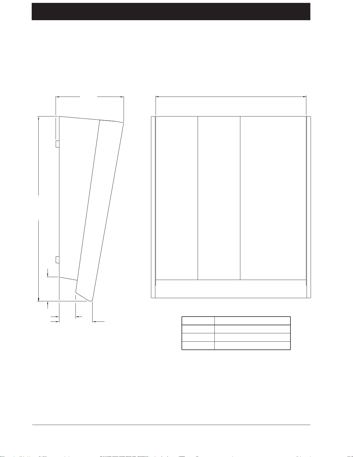
Di men si on s
(21.10")
536.00mm
196.80mm
(7.75")
DIMENSION ’X’
70.50mm
47.50mm
(1.87")
(2.22")
96.30mm
(3.79")
Console
8 ch.
16 ch.
24 ch.
Dimension ’X’
460.00mm (18.11")
678.53mm (26.71")
920.73mm (36.25")
noitallatsnI4991 rebmeceD2.2
Page 11

Precautions and Safety Ins tructions
General Precautions
Caution!
Handling and Transport
Power Supplies & cables
Avoid storin g or using the mixing console in condit ions of excessive heat or cold , or
in positions wh ere it is like ly to be subjec t to vibr ation, dust or mo isture . Do not use
any liquids to clean the fascia of the unit: a soft dry brush is ideal. Use only water
or ethyl alcohol to clean the trim and scribble strips. Other solvents may cause
damage to paint or plastic parts.
Avoid using the console close to strong sources of electromagnetic radiation (e.g.
video monit ors, highpo wer el ectric c abling ): this may cause degrada tion of the aud io
quality due to induc ed voltages in conne cting leads and chassis. For the same reason,
always site the power supply awa y from th e unit.
In all cases, refer servicing to qualified personn el.
The console is supplied in a strong ca rt on. If it is necessar y to move it any dista nc e
after instal lation it is recomme nded that this pac king is used to protect it. Be sure to
disconnect all cabling before moving. If the console is to be regularly moved we
recommend that it is installed in a foamlined flightcase. At all times avoid applying
excessive force to any knobs, switches or connectors.
Always make sure t hat the powe r sup ply un it (PSU) has b een set to the same vo ltag e
as the mains suppl y
Signal Levels
Warning!
Always use the power supply a nd cable supplied with the mixer: the use of alternative
supplies may cause damage and voids the warranty; the extension of power cables
may result in malfunc ti on of the mixi ng consol e.
Always switch the power supply off before connecting or
disconnectin g the mixer power cabl e, removi ng of install ing
modules, and servicing . In the event of an electrical storm, or large
mains voltag e fluctu atio n s, immed i ately sw itch off the PSU an d
unplug from the mains.
Always ensure that you use the corre ct PSU for you r mixer.
It is important to supply the correct input levels to the console, otherwise signal to
noise ra tio or distort ion p erforma nce m ay be de graded; and in e xtreme case s, dam age
to the internal circuitry may result. Likewise, on all balanced inputs avoid sources
with large c om mo nm ode DC, AC or RF volt ag es, as the se wi ll re duc e the a va ila bl e
signal ran ge o n the inputs. Note th at 0dBu = 0.775V RMS.
Refer to the Speci fic a ti ons sec t ion for deta i ls of in put and outp ut lev el s.
Installa tio n December 1994 2.3
Page 12

Mains Installation
Before switching on the K1 console, check that the mains vol tag e
selector on the power supply unit is set to the correct mains voltage
for your area and that the fuse is of the correct rating, this is clearly
marked on the power supply.
Warning!
Do not replace the fuse with any oth er type, as this could become a
safety hazard and will void the warranty.
2.4 December 1994 Installa tio n
Page 13

General Wiring Procedures
To take full advantage of the excellent signal to noise ratio and low distortion of
Soundcraft consoles care must be taken to ensure that incorrect installation and
wiring does not degrade the performance of the desk. Hum, buzz, instability and
Radio Frequency interference can usually be traced to earth loops and inferior
earthing systems. In some areas, especially heavily industrial areas, the incoming
mains earth will not be adequate and a separate technical earth for all the audio
equipment must be supplied. However, check with your local electricity supply
company t o ensu re that safe ty regu lati ons a re not infringe d or negat e d.
The successful, hum free, installation of a system requires forethought, and the
establ ishm ent o f a set of grou nd rules, which m ust b e co nsiste nt ly adhe re d t o at all
stages of installation.
Initial Wir ing
Considerations
• For optimum per form a nc e, it is esse nt ial fo r the ear thi ng syste m to be cle an
and noise free , as al l signal s are refe re nc e d to this e ar th. A cent ra l poi nt
should be dec id ed on for the main eart h point syste m , and all earths shoul d
be ‘star f ed’ from this point. It is common elec trical practice to ‘daisy
chai n’ th e ea rth s to all e lec tr ic a l out let s but th is me t hod is un suit ab le for
audio insta ll a ti ons. The prefe rre d m e tho d is to run an indivi dua l e arth wire
from eac h out let , ba ck to the syste m star po int to pr ovi de a safet y ear th
scre e n re fe rence fo r eac h piece of equipmen t.
A separate eart h wire shou ld also be run from eac h equi pm en t rack an d area ,
to the sta r po int . This ma y or m ay not be use d de pe ndi ng on c ircumst an ce s,
but it is easier to insta ll in the first pl ace , tha n lat er whe n prob lem s ari se.
The loca t ion of the sta r point should be a conve nient, easil y a cc es sibl e pl a ce ,
prefera bly at the re ar of the consol e or in the main equi pm e nt rac k.
• Install separa te ‘c lea n’ a nd ‘d irty’ mains out le t s, wir ed individually ba c k to
the incomi ng mains dist rib uti on box. Use the ‘cle an’ supp ly for all audi o
equipm e nt and the ‘di rty ’ su ppl y for all li ght ing , vending machines etc.
Never mix the two system s.
• If necessary, to provide sufficie nt isolation from ma i ns borne interference,
install an isol atin g transfo rm er. This shoul d be provide d with a Far ad ay
Shield wh ich m ust be co nne c te d wit h ear th.
• Never locate t he incom in g mai ns distr ibution box near a udi o equi pment,
especially tape recorders, which are very sensitive to electro-magnetic field s.
• Ensure that all equipment rac ks ar e conn ect ed to ear th, via a separa t e wire
back to the star point.
• Equipm e nt whi ch ha s un ba la nc e d inp uts and outputs may ne e d to be isol a te d
from the rac k to prev en t earth loops.
Installa tio n December 1994 2.5
Page 14

Audio Wiring
Having pr ovide d all equip ment wit h power a nd eart hing con nectio ns, conside ration
must be given to the method of providing audio interconnection and adequate
screen ing of those interc onnections. This mu st be done in a logical seque nce to avoid
problem s and assist in the loc al isa tion of problem equi pm ent.
• Connect the Monitor system to the console and check for any hum, buzz, or
RFI. Only when you are sat isfi e d with the quie tness o f the consol e and t he
monitor syste m should you proce ed wit h the next ste p.
• Connect stereo tape rec orde rs, echo a nd fo ldb ac k sends one at a tim e,
checki ng a nd isol a ti ng a ny connection whi ch de gra de s per formance .
• Connect all other peripheral devices.
• Connect all microphone lines.
By following this sequence much time and future trouble will be saved, and the
result will be a quiet , stabl e system.
Shielding
Audio equipment is supplied with a variety of input and output configurations,
which must b e taken into c onsideration w hen decidi ng where the sc reen conne ctions
should be made. There are three sources of unwante d signal being impressed on the
screen, which are as follows:
• Extraneous elect rost at ic or ele c tr om ag neti c fie lds.
• Noise and inte rf er ence on the eart h li ne .
• Capacitive coupli ng between th e sc reen and signa l wi re s.
To minimise the adverse affe cts of the unwant ed coup ling to th e signal wire s, it is
import ant that the screen is connec ted at one end only, i.e . the screen must not carry
any signal current. Any signal on the wires within the screen will be capacitively
coupled to the screen. This current will ultimate ly be return ed to the source of the
signal, eithe r directly, if t he screen is c onnected at the signal sour ce end, or i ndirectly
via the e arth ing syste m, i f the sign al is conne c ted a t th e signa l desti na tion e nd . T he
indire ct c onnection wi ll cause an increase in high frequency c ross-talk, and s hould
be avoided whe re ver possibl e .
Therefore, in general, always connect the shield only at the signal source end. In
high RF area s, the screen can also be conne cted to earth via a 0.01µF capa citor. Thi s
will present a short circuit at RF frequencies, thus lowering the effective shield
impedance to ground. However, at low audio frequencies the reactance of the
capaci to r wil l be suffi ci e ntl y hi gh not to ca use a n ear th l oop pr obl em .
Points to Remember
• In all cases, use good quali ty twin sc re en ed aud io ca ble. Chec k for
instability at the output.
• Always connect both conducto rs a t both ends, and ensure that the screen is
only connected at one end.
• Do not disconnect the mains earth from each piece of equipment. This is
needed to prov ide bot h safet y and scr een ret urns to the system sta r point .
• Equipment whi ch ha s ba lan ce d i nput s and outp uts m ay nee d to be
elect rica ll y isola te d fro m the equipm e nt rac k and/ or ot he r equi pm en t, to
avoid earth loops.
2.6 December 1994 Installa tio n
Page 15

It is im portant to re m em ber that a l l equipment whic h is c on nected t o the ma i ns i s a
potential source of hum and interference and may radiate both electrostatic or
electromagnetic rad iation. In addition, the ma ins will also a ct as a c arrier for many
forms of RF interference generated by electric motors, air–conditioning units,
thyristor light dimm ers etc. Un less the e arth syste m is cl ean, al l attempt s to impro ve
hum noise leve ls will be futile. In extrem e cases the re will be no alternative but to
provide a completely separate and independant ‘technical earth’ to replace the
incoming ‘noisy earth’. However, always consult your local electricity supply
authori ty to ensure that sa fe ty regulations are not bei ng infringed.
Installa tio n December 1994 2.7
Page 16

Connections
Wiring conventions
MICROPHONE INPUTS TALKBACK MICGROUP & MIX OUTPUTS
The K3 uses two different types of audio connector: 3-pin XLR and 1⁄4" 3-pole
jacks. This section describes how to connect external equipment to the console.
Correc tly-m a de cables of the proper typ e will ensure peak pe rfo rm an ce from your
mixer.
3-pole XLR
222
111
333
Socket(female) Socket(female)
GROUND (SCREEN)
COLD (OUT OF
PHASE SIGNAL)
HOT
(IN PHASE SIGNAL)
1
4
/"Stereo Jack Plug used as balanced Input/Output:
Plug(male)
GROUND
GROUND
SIGNAL
Hi-Z Input, Stereo Inputs, 2-Track Inputs, Matrix, Mono Output
Tip - HOT(IN PHASE SIGNAL)
Ring - COLD(OUT OF PHASE SIGNAL)
Sleeve - GROUND(SCREEN)
1
4
/"Stereo Jack Plug used as a ground compensated output:
Monitor Outputs, Aux Outputs, PFL Output
Tip - HOT(SIGNAL)
Ring - GROUND SENSE
Sleeve - GROUND(SCREEN)
1
4
/"Stereo Jack Plug used as an unbalanced Insert:
Mono, Mix and Group Inserts
Tip - RETURN FROM
EXTERNAL DEVICE
Ring - SEND TO EXTERNAL DEVICE
Sleeve - GROUND(SCREEN)
1
4
/"Stereo Jack Plug used as an unbalanced Output:
Direct Outputs
Tip - SIGNAL
Ring - GROUND
Sleeve - GROUND(SCREEN)
1
4
/"Stereo Jack Plug used as a Stereo Output:
Headphones
Tip - LEFT SIGNAL
Ring - RIGHT SIGNAL
Sleeve - GROUND(SCREEN)
2.8 December 1994 Installa tio n
Page 17

Block Diagrams
Mono Input
Stereo Input
Master Section
Block Diagrams December 1994 3.1
Page 18

Mono Input Module
3.2 December 1994 Block Diagra ms
Page 19

Stereo Input Module
Block Diagrams December 1994 3.3
Page 20

Master Sectio n
3.4 December 1994 Block Diagra ms
Page 21

4. Functional Descriptions
Mono Input Module
Stereo Input Module
Matrix/Master Section
Functional Descriptions December 1994 4.1
Page 22

1
Mono Input Channel
2
3
4
5
The mono i nput is pr ovide d wit h XLR and j ack connec tors, eith er of which may be
used for any level of input signal. Normally the XLR signal is used, but inserting
a jack automa tica lly disconn ect s the XLR sock et, and app lies the jack signa l to the
input.
The channel is provid ed with an Insert Point usin g an unba lanc e d send an d retur n,
at a nominal level of -2dBu. The signal is accessible via a single 1/4" jack on the
rear connector panel. The insert point is permanently pre-EQ.
1 The 48V switch applies 48V phantom power to the input XLR. Note th at 48V
is never a pplied to the ja c k so ck et .
6
2 The SENS (Sensiti vity) con trol adju sts the sensiti vity of both the XLR and jack
inputs and in combination with the RNGE switch gives two sensitivity ranges:
-15dBu to -70dBu a nd + 10dB u to -40dBu .
3 The RNGE (Range) switch lowers the sensitivity of the input when pressed,
allowing line leve l signals to be used.
7
4 The Ø (PHASE) switch reverses the pha se of the select e d input when pr esse d.
The switch should norma lly be rele ased .
5 This switch inserts a second order HI-PASS FILTER into the channel path.
The frequency is fixe d at 100 Hz .
10
11
12
13
14
8
Equalise r
6 The EQ section has four bands. The HF and LF sections have a shelving
response at a fixed frequency. The Two MID sections have a peaking response at
a variable frequency.
• The HF control giv es 15d B of cut or boost at 12 kHz .
9
• The LF control gives 15dB of cut or bo ost at 60Hz .
• The Hi-Mid control gives 15dB of cut or boost at 400-10k Hz, selected by the
Hi-Mid frequency control.
• The Low-Mid cont rol gives 15d B of cut or boost at 60Hz- 1. 5kHz, select e d by
the Low- Mid freque nc y co ntr ol.
7 The EQ section is switched in by the EQ switch. Togg ling this swit ch p rovide s
a simple me t hod of heari ng t he eff ec t of the e qua li ser sett in gs.
Auxiliary Send s
8 Signal is sent to the Aux 1-6 busses v ia four LEVEL c ontro ls. Th ese ha ve unity
gain when fully clockwi se , a nd are switched pre-or post- fader in pairs by the PRE
buttons.
The 5-6 swi tch switc hes the sign al from t he secon d pair of l evel cont rols awa y from
busses 3 & 4 and onto busses 5 & 6.
4.2 December 1994 Function al Descript io ns
Page 23

Interna l links are fitted which enabl e send pots 2 and 4 to be disconnecte d from their
respectiv e PRE switch es, and linke d indepe ndent ly to the pre- or post-fade signals.
Routi ng
9 The PAN control determ ines the position of th e signal wit hin the ste reo ima ge.
In the centre position there is a 4.5dB level drop. Pan left feeds the signal to odd
numbere d busses and Mix Left, pan right feeds to ev en numb er ed busse s and Mix
Right.
10 The long-travel FADER has 10dB of gain an d is the ma in leve l contr ol for the
channel, enabling rapid and accurate control of the channel output level. When
mixing, you will get optim um headroom and signal-t o-noise ratios by ke ep ing the
fader at abo ut the unity gain (0) mark. Avoid running th e input sensi tivity to o high,
and the fader resultingly low, since this gives very little headroom. Similarly,
running the input sensitivity very low, and the fader fully up (10dB of gain) will
increase noise levels, and does not allow any increase in gain on the fader should
the source signal drop unexpectedly.
11 The ON switch enables the post EQ, post-Insert channel signal path: when
released, all post-fade Auxiliary Sends and all routing outputs are muted. We
recommend that you switch all unused channels OFF to prevent unwanted noise
being added to a ny pa rt s of the m ix.
12 The signal is sent to the stereo mix bus, mono bus and 4 group busses using
the MIX, MNO, 1-2 & 3-4 switches respectively, subject to the position of the
PAN control (see above).
The mono bus is fed direc t ly from the post- fade r signa l .
13 The PFL switch feeds the pre-fade signal into the monitor/phones system
where it replaces the selected monitor source.
The red LED illumina tes when the PFL switch is pressed, and also serves as a PEAK
(PK) indicator , monito ring the sign al at the out put of the Equa lise r and illumi nate s
at 6dB before clip pin g.
14 The green SIG LED monitors the signal at the input amp and illuminates
when the signal exceeds -30dBu.
The post-fa de signa l is sent t o the unba lanc ed DIRECT OUTP UT jack on the rear
panel.
Functional Descriptions December 1994 4.3
Page 24

Rear Connectors
INPUT (3 pin female XLR)
DIRECT O/P
NSERT
I
HI-ZI/P
IC
M
Pin 1 Ground
Pin 2 Signal Hot
Pin 3 Signal Cold
JACK INPUT (1/4" TSR Jack)
Tip Signal Hot
Ring Signal Cold
Sleeve Ground
INSERT SEND/RETURN, (1/4" TSR Jack)
Tip Return signal
Ring Send signal
Sleeve Ground
DIRECT OUTPUT (1/4" TSR Jack )
Tip Signal Hot
Ring Ground
Sleeve Ground
4.4 December 1994 Function al Descript io ns
Page 25

Stereo Input Ch annel
0
-5
+5
-10
-15
-20
+10
1
1 The SENS (Sensitivity) control adjusts the sensitivity of A or B inputs from
2
+14 to -16dBu.
3
4
2 Pressing B switches the input source from line A to line B, both of which are
electro nically ba lanced, from 1/4" Jac k i nput s on the re a r pa ne l.
The left an d right jacks of bo th A and B inputs are normalised together via the switch
contacts of the right jack so that a mono signal, plugged into the left jack only, is
fed equa ll y to left a nd ri ght .
Input B may be linke d for an inte rna l RIAA filter.
5
3 Pressing LEFT (Ø) PHASE inverts the phase of the left channel on the selected
input.
4 This switch inserts a second order HI-PASS FILTER into the channel path.
The frequency is fixe d at 100 Hz .
6
Equalise r
5 The EQ section has four bands. The HF and LF sections have a shelving
response at a fixed freque nc y. The Two MID sections have a peak/dip re sponse at
fixed frequenc i es.
• The HF control gives 15d B of c ut or boost at 12 kHz .
7
• The LF control gives 15dB of cut or bo ost at 60Hz .
• The Hi-Mid control give s 15dB of cut or boost at 5kHz.
• The Lo-Mid control giv es 15d B of cut or boost at 250Hz .
6 The EQ section is switched in by the EQ switch. T ogg ling this switc h p rovide s
a simple me t hod of heari ng t he eff ec t of the e qua li ser sett in gs.
8
9
10
11
12
13
Auxiliary Send s
7 Signal is sent to the Aux 1-6 busses v ia four LEVEL c ontro ls. Th ese ha ve unity
gain when fully clockwi se , a nd are switched pre-or post- fader in pairs by the PRE
buttons.
The 5-6 swi tch switc hes the sign al from t he secon d pair of l evel cont rols awa y from
busses 3 & 4 and onto busses 5 & 6.
The pre or post-fader source for Aux 1 & 2 is a mono sum of the left and right
channel signa l s. Th e Pre or post-fa der source for the for Aux 3 & 4 (5 & 6) can be
either stereo (left feeds 3 or 5, right feeds 4 or 6) or a mono sum. This is selected
by inter nal jumpers.
Functional Descriptions December 1994 4.5
Page 26

0
-5
+5
-10
-15
-20
+10
1
2
3
4
Routing
8 The BAL (Balanc e) control determine s the rel ative leve ls of the L an d R signals.
In the centre position its gai n is unity. Turning it fully clock wise incre ases the right
signal by 4.5dB, and reduces th e left signa l to zero. Ful l anticloc kwise r otation has
the opposite effect. Balanc e left biases the signa l to odd numbere d busses, balanc e
right to even busses.
9 The long-travel FADER has 10dB of gain a nd is the mai n l ev el cont rol for the
channel, enabling rapid and accurate control of the channel output level. When
mixing, you will get optim um headroom and signal-t o-noise ratios by ke ep ing the
fader at abo ut the unity gain (0) mark. Avoid running th e input sensi tivity to o high,
and the fader resultingly low, since this gives very little headroom. Similarly,
running the input sensitivity very low, and the fader fully up (10dB of gain) will
5
increase noise levels, and does not allow any increase in gain on the fader should
the source signal drop unexpectedly.
10 The ON switch enables the post EQ, post-Insert channel signal path: when
released, all post-fade Auxiliary Sends and all routing outputs are muted. We
recommend that you switch all unused channels OFF to prevent unwanted noise
being added to a ny pa rt s of the m ix.
10
11
6
11 The signal is sent to the stereo mix bus, mono bus and 4 group busses using
the MIX, MNO, 1-2 & 3-4 switches respectively, subject to the position of the
BAL control (see above ).
The mono bus is fed direc t ly from the post- fade r signa l .
7
12 The PFL switch feeds a mono sum of the stereo source pre-fade signal into
the monitor/phone s syst e m where it re pla c e s the sele cte d m oni to r so urc e .
The red LED illumina tes when the PFL switch is pressed, and also serves as a PEAK
(PK) indicator, monitoring the left and right signals post-EQ, pre-fader and
illumi na tes when either cha nn el reac he s 4dB before cl ipp ing .
13 Th e gree n SIG LED moni tor s the left and ri ght signa l s at the inpu t amp and
8
illuminate s whe n the signal at eithe r point exce e ds -30d Bu.
9
12
13
4.6 December 1994 Function al Descript io ns
Page 27

Rear Connectors
LINE A and B, LEFT and RIGHT (1/4" TSR Jacks)
Tip Signal Hot
Ring Signal Cold
Sleeve Ground
Functional Descriptions December 1994 4.7
Page 28

Group/Matrix Section
5
Group Output
1 The Group FADER c ontrol s the l evel o f the Gr oup sign al f ed to the Inser t Send,
with unity gain at the top of the fader.
The insert point is pre-fade, and uses an unbalanced send and return at a nominal
level of -2dBu. The insert send and return are on a single 1/4" jack on the rear
connec to r pa ne l.
6
2 The MIX switch routes the post-fade group signal to the left and right stereo
mix busses, depe nd ing on the setti ng of the STE swit ch (see below).
8
3 If STE (Stereo) is pressed, the odd-numbered group is sent to MIX Left, the
even-numb er ed to MIX Right .
7
9
6
8
7
9
3
If STE is not pressed, both odd and eve n groups a re sent in mono to MIX Le ft and
Right.
4 The AFL switc h f eeds t he po st fa de g roup sign al t o the moni tor /ph ones sect ion
where it replaces the selected monitor source.
5 The Group output levels are metered (post fader) by four peak-reading
12- segm en t LE D BARG RAPHS at the top of the module; the meters are calibrated
for 0 at +4dBu output. The meter response is peak-reading.
The meters can be switched to read the matrix output signal by pressing the GRP
METERS TO MATR IX switch on the Master section.
The group output signal is electroni ca l ly balanced and is availa ble on a male 3-pin
XLR co nne c tor on the re a r pa nel.
2
4
Matrix section
The matrix section provides 4 matrix outputs, each of which is a m ix of th e four
post-fade Group signals. Ea c h output contains receiv e l evel controls, output fa der,
talkbac k and AFL bu ttons.
6 The receive LEVEL controls 1-4 control the amount of each post-fade Group
1
signal fed to the matrix ou tpu t fader.
7 The Matrix output rotary FADER controls the output level fed to the matrix
output (ba la nc e d 1/ 4" ja c k on re a r pa ne l) .
8 The AFL bu tton feeds t he post-fa de Matrix output signal to t he phone s/monitor
outputs, replacing the selected source.
9 Pressing the TB button feeds ta lkba ck signa l from the talkba ck mic amp on the
Master section to the Matrix output, after the output fader. The signal replaces the
Matrix output signa l .
The LED METERS above the group/ma t rix sectio n can be swit ch ed as a block to
read the four post fade matrix output signals. This is done by means of electronic
switching activated by pressing the GRP METERS TO MATRIX switch on the
master section.
4.8 December 1994 Function al Descript io ns
Page 29

LR
MIX/SOLO
AUX
1
2
AUX
2
2
AUX
3
2
AUX
4
2
AUX
5
2
AUX
6
2
TALKBACK
2
2-TRACK
REPLAY
2
MONO
-
20
L/R
-
40
0
5
10
MNTR/
PHONES
3
15
2
1
20
25
30
40
50
8
15
12
9
6
3
0
-3
-6
-9
-12
-15
SIG
5
4
3
1
0
5
4
3
1
0
5
4
3
1
0
5
4
3
1
0
5
4
3
1
0
5
4
3
1
0
5
4
3
1
0
5
4
3
1
0
-
15
8
GRP METERS
TO MATRIX
5
4
0
PHONES
Master Sect ion
9
The m aster sectio n cont ains the co ntrol s for the ma in ste reo and mono o utput s,
auxiliar y outputs, contro l room/phones output s, two-track inputs and talkbac k input.
Main Stereo Outputs
6
7
8
9
10
AFL
6
7
8
9
10
AFL
6
7
8
9
10
AFL
6
7
8
9
10
AFL
6
7
8
9
10
AFL
6
7
8
9
10
AFL
6
7
8
9
10
AUX
MIX
6
7
8
9
10
MIX
-
5
0
AFL
15
12
11
13
14
B
4
-
10
2
3
10
1
6
10
PFL/AFL
7
8
9
2TK
6
5
7
8
1 The Stereo Mix Left and Right signals are cont rolled by the L/R FADER. Unity
gain is a t the top of the f ad er . Th e le ft a nd ri ght outputs are el e ct ronicall y b al a nc ed
and appea r on m ale XLR c onn ect ors on th e re ar pa ne l.
Mix Left and Right pre-fade Insert Points are provided, using an unbalanced send
and retu rn on s in gle 1/ 4" ja c k sockets on th e re ar panel.
Mono Output
The MONO output is electronically balanc ed and appears on a 1/4" jack on the rear
panel.
2 The Mono Master FADER controls the output level with unity gain fully
clockwise.
The sourc e of the mo no fader is normally t he mono bus i tself, but internal j umpers
allow this to b e chan ged to be a derive d mono sum of the pre-f ade (post insert) Mix
Left and Right signals.
3 The AFL switch routes the post-fade mono signal to the monitor/phones
outputs, replacing the selected source.
2-Track Returns
4 Ther e are two 2-tra ck retu rn in puts, e lec troni cal ly bal anc ed, from 1/4" j acks on
the rear pa nel. T he 2-TRACK REPLAY control adjusts the sensitivity of both
inputs and is nomi nall y -10 dBV for unity gain with the contr ol fu lly cloc kwi se.
Pressing the B butt on sele cts t he 2 TRK B i nputs. The MIX button routes the signa l
to the stere o mi x out put s.
The selected 2-track input can be monitored on the monitor/phones outputs by
pressing the 2TRK button on the monitor output sectio n.
Monitor and headphones outp uts
5 The Monitor Outputs and Headphones output share a common signal source
and are controlled by the MNTR/PHONES LEVEL control. The Monitor outputs
are via L eft and Rig ht 1/4" jac ks on the re ar pane l with ground compe nsated outpu ts.
The phones output socket is a stereo 1/4" jack on the front panel. The Monitor
outputs are automat ica lly cut off when a jack is inserte d in the PHONES soc ket.
Functional Descriptions December 1994 4.9
Page 30

LR
MIX/SOLO
AUX
1
2
AUX
2
2
AUX
3
2
AUX
4
2
AUX
5
2
AUX
6
2
TALKBACK
2
2-TRACK
REPLAY
2
MONO
-
20
L/R
-
40
0
5
10
MNTR/
PHONES
3
15
2
1
20
25
30
40
50
8
15
12
9
6
3
0
-3
-6
-9
-12
-15
SIG
5
4
3
1
0
5
4
3
1
0
5
4
3
1
0
5
4
3
1
0
5
4
3
1
0
5
4
3
1
0
5
4
3
1
0
5
4
3
1
0
-
15
8
GRP METERS
TO MATRIX
5
4
0
PHONES
6 A solo system of pre-fade (inputs) and post-fade (outputs) feeds the monitor
and phone s out put s. No rma lly, all act ive AF L & PFL signa l s are summ e d toge th er
9
and fed to the monitor and phones outputs. The PFL/AFL LED ill uminat es to
show that a PFL/AFL is active. This overrides the Stereo Mix or 2-Track signal
which is norma ll y fed to the monit or/ phon es out put (see below ).
7 The signal source for the Monitor and Phones outputs is selected using
the 2TRK button. If this is not pressed , the po st-fade st ereo Mix sign al i s fed t o the
monitor outputs. If 2TRK is pres sed, the post- fa de signa l from the 2-T rac k ret urn
6
7
8
9
10
AFL
6
7
8
9
10
AFL
6
7
8
9
10
AFL
6
7
8
9
10
AFL
6
7
8
9
10
AFL
6
7
8
9
10
AFL
6
7
8
9
10
AUX
MIX
B
6
7
8
9
10
MIX
15
12
11
13
14
4
section is fed to the monitor ou tputs. Any PFL/AFL operatio n will overri de the Mix
or 2-Track signal.
8 A front pane l jac k is provid ed for th e conn ec tion of ste re o head phon es.
Metering
9 Two 12-segment peak-reading LED BARGRAPH METERS follow the
Monitor/Phones selection to display the post-fade Stereo Mix, 2-Track return or
AFL/PFL signa l s.
10 The GRP M ETERS TO MATRIX switc h selects t he post-fade Matrix out put
signals as the source for the Group m ete rs, instea d of the norm a l Group signa l .
Talkback
The talkback system provides communication to the Group, Matrix and Aux
outputs.
11 The TALKBACK control adjusts the level of the Talkback Mic input. The
sensitivity of the mic input is variab le betwe e n 0dBu and -50dB u.
12 The 3-pin XLR co nnec tor provid es an unba lanc ed TALKBACK INPUT for
a local microp hone or gooseneck mic.
13 The momentary AUX button routes the talkback microphone signal to
-
10
-
5
0
AFL
2
3
Auxiliary busses 1-6 whe n pres sed.
14 The momentary MIX button routes the talkback mic signal to the Mix L and
R busses when pressed.
10
In addition, the tal kba c k mic signa l is per mane nt ly fed to the TB switch es on ea ch
matrix output, where it can be locally injected as required.
Auxiliary outp uts
15 The AUXILIARY SEND MASTER LEVEL cont rols set t he output level of
the Auxiliary Send mixes. 10dB of gain is provided with the controls fully
clockwise, with a nominal unity gain at position 7.
10
6
PFL/AFL
7
8
9
2TK
1
6
5
7
8
The AFL button switch es the po st fade r signa l to the moni to r/p hone s output.
The Auxiliar y out put s ar e groun d com pe nsat e d at +4dB u on 1 /4" Jacks on th e re ar
panel.
4.10 December 1994 Function al Descriptions
Page 31

PFL Output
A ground com pensated output is pr ovided for the PFL/AFL signal. Thi s is via a 1/4"
jack socket on the rear panel.
Rear Connectors
MIX/MONO / GRP OUTPUT S (3-pin male XLR)
Pin 1 Ground
Pin 2 Signal Hot
Pin 3 Signal Cold
MIX/GRP INSERT SEND/RETURN (1/4" TSR Jack)
Tip Return signal
Ring Send signal
Sleeve Ground
AUXILIARY, MONITOR, PFL OUTPUTS (1/4" TSR Jack)
Tip Signal Hot
Ring Ground Sense
Sleeve Ground
PHONES OUTPU T (1/4" T SR Jac k) (Front -pa ne l moun te d)
Tip Left Signal
Ring Right Signal
Sleeve Ground
TALKBACK MIC IN (3 pin femal e XLR)
Pin 1 Ground
Pin 2 Signal
Pin 3 Ground
2-TRACK RETURNS A,B (1/4" TSR Jack)
Tip Signal Hot
Ring Signal Cold
Sleeve Ground
M
M
M
Functional Descriptions December 1994 4.11
Page 32

4.12 December 1994 Function al Descriptions
Page 33

Specifications
Specifications December 1994 5.1
Page 34

Specifications
Frequency Response
Any input to any output 20Hz - 20kHz, +0/-0.5dB
Total Harmonic Distortion
(All measurement s at +20dBu)
Line In to Group or Mix out Less than 0.01% @ 1kHz
Less than 0. 025% @ 10kHz
Noise
(22Hz-22kHz band wid th, unwei ght ed)
Mic Input Equiva l ent Inp ut Noise Less than -127.5 dBu
(200ohm source)
Input and Output Impe dances
Mic Inputs 2kΩ ba lanced
Hi-Z and Stereo Inputs Greater than 10kΩ balanced
Aux Outputs 75Ω ground compensated
Group, Mix and Ma tr ix Out put s 75Ω ba lanced
Input and Outp ut Levels
Mic Input Sensiti vity (XL R) -15dBu to -70dBu
Line Input Sensi tivit y (0.25" jack) +10dBu to -40d Bu
Insert Sen d/Return -2dBu nom ina l
Aux Outputs +4dBu nominal
Group, Mix and Ma tr ix Out put s +4dBu for 0VU
5.2 December 1994 Specifications
 Loading...