

Page 1
USER GUIDE
Page 2

© Soundcraft Electronics Ltd.1994
All rights reserved
Parts of the design of this product may be protected by worldwide patents.
Part No ZM0055/01
Information in this manual is subject to change without notice and does not represent
a commitment on the part of the vendor. Soundcraft Electronics Ltd. shall not be
liable for loss or damage whatsoever arising from the use of information or any error
contained in this manual.
No part of this manual may be reproduced, stored in a retrieval system, or transmitted, in any form or by any means, electronic, electrical, mechanical, optical,
chemical, including photocopying and recording, for any purpose without the
express written permission of Soundcraft Electronics Ltd.
It is recommended that all maintenance and service on the product should be carried
out by Soundcraft Electronics Ltd. or its authorised agents. Soundcraft Electronics
Ltd cannot accept any liability whatsoever for any loss or damage caused by service,
maintenance or repair by unauthorised personnel.
Soundcraft Electronics Ltd.
Cranborne House,
Cranborne Road,
Cranborne Industrial Estate,
Pottersbar,
Herts.,
EN6 3JN
England.
Tel: 0707 665000
Fax: 0707 660482
Page 3

Table of Contents
Introduction 1
Introduction to the GP1 2
Precautions and Safety Instructions 3
PPS110 Circuit Diagram 6
Connections 7
Block Diagrams 9
Block Diagram - Inputs 10
Block Diagram - Outputs 11
Mono Input Module 13
Mono Input Module 14
Std Stereo Line Input 17
Standard Stereo Line Input Module 18
Basic Stereo Line Input 21
Basic Stereo Line Input Module 22
Master Section 25
Master Section 26
Monitor Module 29
Monitor Module 30
Appendices 33
Technical Specifications 34
Dimensions 35
Warranty 36
Page 4

Page 5

Introduction
Introduction 1
Page 6

Introduction to the GP1
Overview
The GP1 Location Broadcast Mixer is available in three frame sizes: 6, 8 and 12
Input Modules. The GP1 also has an Output & Meter Master Module ,and a Monitor
Module.
The Output meters are VU or PPM.
The GP1 is lightweight, for portability, whilst also being rugged.
The power consumption is low to ensure a long usable life for the internal batteries
(typically 8-10 hrs from Ni-Cd cells, and 15-20 hrs from alkaline cells - both figures
for the 12 Input version).
Although the GP1 is primarily designed for remote use with on-board battery power,
the mixer may also be rack mounted (8 Input variant only), or furniture mounted. It
may be mains powered via the PPS110 power supply.
2 Introduction
Page 7

Precautions and Safety Instructions
General Precautions Avoid subjecting the mixer to conditions of excessive heat or cold, or installing it
in positions where it is likely to be subject to vibration, dust or moisture. Do not use
any liquids to clean the fascia of the unit: a soft dry brush is ideal. Use only water
or ethyl alcohol to clean the trim and legend strips. Other solvents may cause damage
to paint or plastic parts.
Avoid using the mixer close to strong sources of electromagnetic radiation (e.g.
video monitors, high-power electric cabling): this may cause degradation of the
audio quality due to induced voltages in connecting leads and chassis. For the same
reason, always site the mixer power supply away from the mixer.
Caution! In all cases, refer servicing to qualified personnel.
Power supply & cables Always use a power supply and power cables specified for the mixer: the use of
alternative supplies may cause damage and voids the warranty; the extension of
power cables may result in malfunction of the mixer.
Warning! Before switching on the power supply, check that the mains voltage selectors
are correctly set to the voltage for your area, and that the fuses are of the correct
type and rating. This is marked on the case of the power supply. Do not replace
the fuses with any other type, as this could become a safety hazard and will
void the warranty.
PPS110
Power Supply
Warning! Always switch the power supplies off before connecting or disconnecting the
mixers power cables, removing or installing modules, and servicing. In the
event of an electrical storm, or large mains voltage fluctuations, immediately
switch off the PSU and isolate from the mains. The power supply is connected
to the mixer via the 4-way socket, marked DC Power, on the rear panel.
Always ensure that you use a suitable power supply for the mixer. The GP1 may
use a PPS110 power supply (see details of the power connection below), or a suitable
external source.
The mixer is powered from an external power supply when the POWER switch on
the rear panel is set to EXT.
A PPS110 power supply is supplied with all variants of the GP1. The power supply
is capable of operating over a wide range of mains input voltages by means of a
comprehensive set of selectable voltage settings. It is important to ensure that the
correct voltage setting has been selected for the level of local AC mains input voltage
supply, for safe, uninterrupted-operation of the units.
Warning! DO NOT CHANGE THE AC MAINS VOLTAGE SETTING WITHOUT
FIRST DISCONNECTING THE MAINS PLUG FROM THE MAINS
SOCKET.
The power supply is provided with an IEC-type mains connector, coupled with a
voltage selector with integral AC mains fuse holder. Confirm that the arrow
moulded into the connector unit aligns with the voltage setting that is correct for
your area. Voltage selection should be as follows:
· 100Volt setting for AC Mains Input 100-115Volts AC
· 120Volt setting for AC Mains Input 115-125Volts AC
· 220Volt setting for AC Mains Input 210-225Volts AC
Introduction 3
Page 8

· 240Volt setting for AC Mains Input 230-264Volts AC
To change the selected voltage, prise off the fuse holder square top with a screwdriver-type tool, using the square blade tip in the slot. Pull the fuse carrier assembly
clear of the body, rotate the fuse carrier body until the required input voltage lines
up with the arrow, and then push the fuse carrier back into the connector body.
Warning! DO NOT USE DC MAINS INPUT VOLTAGES
Replacing Mains Fuse Switch the units on/off mains switch to the off position, remove the mains lead plug
from the mains supply socket.
Check the fuse and replace if necessary: also check that the voltage selector is correct
for the mains supply level before switching the unit on again. The correct fuse ratings
are as follows:
220/240 VAC fuse rating T1.0A/250V
100/120 VAC fuse rating T2.0A/250V
Warning! TO AVOID THE RISK OF FIRE REPLACE ONLY WITH THE CORRECT
VALUE AND TYPE OF FUSE AS INDICATED ON THE UNIT.
In the event of repeated failure of the mains fuse, consult the dealer from whom the
unit was purchased.
Technical Specification Mains Input Voltages (Nominal): 240/220/120/100 VAC @50/60Hz
PPS110 XLR pin out:
Pin 1 Chassis
Pin 2 0V
Pin 3 Battery charging voltage (28V DC (nominal))
(for charging the internal batteries)
Pin 4 28V DC ( nominal)
Overall Dimensions (Chassis)
Height: 77mm
Width: 140mm
Depth: 172mm
Power Supply Installation Free Standing
The PPS110 is designed to operate as a free-standing unit without requiring any
special cooling arrangement, but should not be accidentally or deliberately covered
in any way.
Rack Mounting
The PPS110 can be provided with an optional 19-inch rack-mounting kit: it occupies
2U of rack space.
Batteries The Location Mixer may also be powered by its own internal batteries: 12 or 16 D
type cells are required: the 6 and 8-input variants use 12 cells, the 12-input variant
uses 16 cells. These may be primary cells or rechargeable cells; all cells must be of
4 Introduction
Page 9

the same type, do not mix types. The access panel for inserting and removing the
cells is on the underside of the mixer.
Warning! DO NOT try to recharge dry (primary cells: they may explode, and the wiring
will melt if this is attempted
Rechargeable cells may be recharged from the power supply. To do this set the
CHARGE switch on the power supply to on.
It is not advisable to charge the cells and use the mixer at the same time: performance
specifications may not be achieved under adverse conditions.
The mixer is powered from the internal cells when the POWER switch on the rear
panel is set to INT.
Signal Levels It is important to supply the correct input levels to the mixer, otherwise signal-to-
noise ratio or distortion performance may be degraded, and in extreme cases damage
to the internal circuitry may result. Likewise, on all balanced inputs, avoid sources
with large common mode DC, AC or RF voltages, as these will reduce the available
signal range on the inputs. Note that 0dBu = 0.775V RMS.
The microphone inputs are designed for use with balanced, low impedance (150 or
200) microphones.
Caution! DO NOT use unbalanced microphones or battery powered condenser microphones
without isolating the phantom power - degraded performance or damage to the
microphone may result.
Introduction 5
Page 10

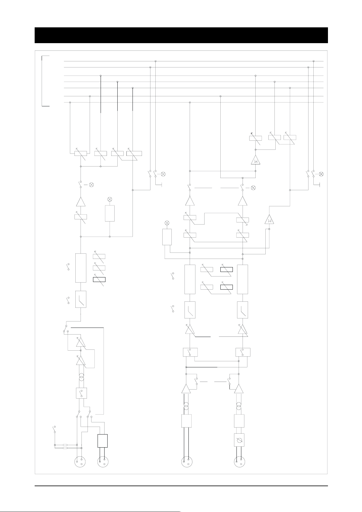
PPS110 Circuit Diagram
LD1
R3
2K4
CHARGE
F4
CHARGE
SW1
SPST
CN2
F1A
1
2 P IN
2
AMBER
F3
F3,16A
DC
0V
CHASSIS
DC
CHARGE
1
2
3
4
5
L1
2U2H
5 P IN
CHOKE
R4
2K4
10000/40V
CN3
D1
1N4001
C5
LD2
GREEN
4 P IN XL R
CABLE CONNECT OR
DC
4
1
RED
WHT
YEL
CHASSIS
CHARGE
0V
GREEN
3
2
PPS-110
UNREGULATED POWER SUPPLY
ISSUE 2
ED3395
240V
C4
10000/40V
C3
2U2F/50V
!
F2
3,15A
F1
3,15A
CN1
4 P IN
123
R2
22R
C2
100N
0.5W
4
C1
100N
R1
47R
RECT1
!
18V5 AC
!
TRANSFORMER
T1
!
0V
220V
120V
100V
DPST
SW2
MAINS VOLTAGE
!
50/60Hz
100V-240V
!
LNE
(I.E.C)
SELECTOR
120V
220V
100V
240V
F5
FUSE
!
A.C.
The Mains input fuse is rated at:
T1.0A/250V Mains Input 220/240V AC
T2.0A/250V mains Input 100/120V AC
CHASSIS
6 Introduction
Page 11

Connections
Wiring Conventions The GP1 uses two different types of audio connector: 3-pin XLR, and
jacks.
XLR Connectors
MALE XLR
12
3
Pin 1 = Ground (Screen)
Pin 2 = Hot (In-Phase)
Pin 3 = Cold ( Out-Of-Phase)
FEMALE XLR
1
Pin 1 = Ground (Screen)
Pin 2 = Hot (In-Phase)
Pin 3 = Cold ( Out-Of-Phase)
2
3
Jack Plugs
1
/4" 3-pole
Tip Ring Sleeve
The Connections are as follows:
Balanced Inputs
Tip Hot (In-Phase) Signal
Ring Cold (Out-Of-Phase) Signal
Sleeve Ground (Screen)
Headphones
Tip Left Signal
Ring Right Signal
Sleeve Ground (Screen)
Introduction 7
Page 12

8 Introduction
Page 13

Block Diagrams
Block Diagrams 9
Page 14
Block Diagram - Inputs
CTL
PFL
PFL
2
POST
AUXES
BUSES
PRE
R
L
AUX2
AUX1
POST
PRE
EQ
HPF
PAN
MUTE
FADER
EQ
LF
MF
HF
AUX2
PK
AUX1
POST
PRE
PFL
PFL
MUTE
BAL
PK
FADER
LF
EQ
EQ
EQ
HF
HPF
HPF
HPF
GAIN
GAIN
MONO_R
MONO_L
GAIN
DIN
PHASE
MIC
LINE
PAD
POWER
PHANTOM
2
3
MIC
1
LINE
PAD
L
LINE
2
3
1
2
3
1
MONO INP UT CH.
R
LINE
PAD
2
3
1
STEREO INPUT CH.
10 Block Diagrams
Page 15

Block Diagram - Outputs
HPHONE 1
METER L
METER R
1
LEFT
3
2
RIGHT
3
1
2
3
AUX 1
1
1
AUX 2
3
2
2
H/P 2
H/P 3
T/B
1
3
2
PHONES 1
EXT
MON
LIMITER
EXT
TALK
AUX 1
AUX 2
EXT
L/R
TALK
BATT
CHECK
L/R
AUX 1
PFL
AUX 2
EXT
TALK TO
T/B MIC GA IN
MONO
MUTE
LINK
LIM
LEFT
RIGHT
LIM
AFL
MUTE
AFL
PAD
2
3
1
EXT L
PAD
2
3
1
T/B
EXT R
MASTER OUT PUT SECTION
MONITOR MODULE
TALK TO
L / R
AUX 2
AUX 1
FADER
TONE
FADER
LEVEL
LEVEL
AUX 1
POST
LEVEL
AUX 2
PRE
OSC
LEFT
PFL
RIGHT
PFL MIX
CTL
PFL
2
POST
AUXES
BUSES
PRE
R
L
Block Diagrams 11
Page 16

12 Block Diagrams
Page 17

Mono Input Module
Mono Input Module 13
Page 18

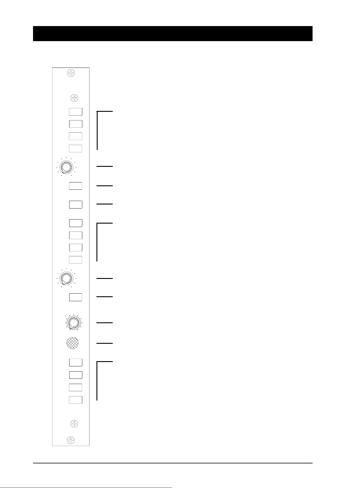
Mono Input Module
Input
PHANTOM
POW
SENS
30
0
-
5
20
-
10
15
0
0
L
1
ER
O
40
10
60
CIM
20
70
35
80
LINE
0
F
H
+
HPF
0
2
3
4
7
5
connector, or 12 Volt T-power where +12 V is applied to pin 2 of the XLR, and
0v is applied to pin 3. The functionality of the PHANTOM POWER switch is
selected by internal jumper/switch settings.
A 12V Phantom Power option is also available. This is also set by links and an
internal switch on the PCB. If this option is used then +12Vis applied to pins 2 & 3
of the XLR.
2 The Phase switch reverses the polarity (hot/cold) of whichever input is in use.
The switch’s released position is the normal setting.
8
MF
1 The PHANTOM POWER switch applies +48V to pins 2 & 3 of the mic XLR
+
EQ
0
LF
+
AUX1
10
AUX2
10
C
6
9
10
11
12
PAN
R
M
UTE
10
PFL
5
15
13
14
0
PK
5
16
3 The SENSitivity control adjusts the gain of either input. The mic range is from
80dB to 15dB gain, the line range is 35dB to -10dB.
4 The LINE switch, when depressed, causes the mic input to be replaced by the
line input.
5 The HPF switch, when depressed, puts a High Pass filter into the signal path.
This removes unwanted low frequency signals. The filter’s -3dB point is at 80Hz,
and the filter has a slope of 12dB/octave.
EQ
6 The EQ switch places the Equaliser section into the signal path.
The EQ section consists of three filters, controlled by the HF, MF and LF controls.
7 The shelving HF control provides a maximum cut/boost of 10dB at 10kHz. The
control is centre-detented at 0dB.
8 The MF control creates a bell envelope which has a maximum cut/boost of
14dB at 2kHz. The control is centre-detented at 0dB.
10
20
30
9 The LF control provides a maximum boost/cut of 10dB at 100Hz. The control
is centre-detented at 0dB.
Auxiliary Sends
10 The AUX1 Level control is used to control the signal level which is sent to the
40
50
60
8
Auxiliary 1 output mix. The signal can be varied between 0dB and infinite attenuation. Aux1 may be selected, via the Master Module, as pre-fade or post-fade.
11 The AUX2 Level control is used to control the signal level which is sent to the
Auxiliary 2 output mix. The signal can be varied between 0dB and infinite attenuation. Aux2 is always post-fade.
Pan
12 The mono input to the module may be positioned within the stereo image, which
is carried by the Left and Right mix buses, by means of the PANorama pot.
14 Mono Input Module
Page 19

PFL
13 The PFL switch routes the pre-fade post -EQ signal onto the PFL mix bus. The
PFL control bus is also activated.
The associated PFL LED is illuminated when the PFL switch is active.
Peak
14 The PEAK LED starts to illuminate when there is 6dB of headroom left.
Output
15 The MUTE switch routes the output from the Fader onto the Left and Right
Main Mix buses, via the PAN pot; it also routes the other post-fade paths, i.e. Aux1
and Aux2.
The associated MUTE LED is illuminated when the Mute switch is active.
16 The 100mm Fader provides 10dB of gain at maximum.
Options An optional input transformer (common to mic. and line) can be fitted.
Jumpers The following table shows how to set the jumpers for phantom power and T-power
options:
Power Options
48V 12V 12V
(48V on (12V on 12V pin 2
pins 2 & 3) pins 2 & 3) 0V pin 3)
Jumper
J12-0V OUT OUT IN
+12V IN IN OUT
Internal Switch
48V/12V Released Depressed Depressed
Rear Connector Two female XLR connectors are provided at the rear of the Mono Input Module.
The top one is for the Mic, the lower one is for the Line input.
The connections are as follows:
Pin 1 Ground (Screen)
Pin 2 Hot (In Phase)
Pin 3 Cold (Out of Phase)
Mono Input Module 15
Page 20

16 Mono Input Module
Page 21

Std Stereo Line Input
Std Stereo Line Input 17
Page 22

Standard Stereo Line Input Module
Input
RHS
0
MONO
SOURCE
0
0
0
0
C
L
10
5
10
10
MUTE
0
5
GAIN
+
+
+
AUX1
R
LINE
DIN
O
L
R
HF
LF
EQ
AUX2
BAL
PFL
PK
10
11
14
12
13
15
1
2
3
1 The LINE/DIN switch allows you to select a nominal level of +4dBu (when
the switch is released) or a nominal level of 10dBV (when the switch is depressed).
2 Pressing the RHS PHASE switch will reverse the phase of the Right-hand
signal.
4
3 The rotary GAIN control provides 0dB at the centre detent, and a cut/boost of
15dB at the extremes of its travel.
8
6
9
7
4 The L and R MONO SOURCE switches operate as follows:
L position R position Effect
Out Out Normal Stereo operation.
Out In Right-hand signal fed to both sides.
In Out Left-hand signal fed to both sides.
In In A mono sum of Left and Right
signals is fed to both sides.
5 The centre-detented BALance control provides a +3db boost to one channel
and a 8dB cut to the other channel at each end of its travel.
5
6 The High-Pass Filter switch, when depressed, puts a High Pass filter into the
Signal path. This removes unwanted low frequency signals. The filters 3dB point
is at 80Hz, and the filter has a slope of 12dB/octave.
EQ
The EQ has two shelving filters.
7 The two shelving filters are in-circuit when the EQ button is depressed.
8 The shelving HF control provides a maximum cut/boost of 10dB at 10kHz. The
control is centre-detented at 0dB.
10
9 The LF control provides a maximum boost/cut of 10dB at 100Hz. The control
20
30
40
50
60
8
is centre-detented at 0dB.
Auxiliary Sends
10 The AUX1 Level control is used to control the signal level which is sent to the
Auxiliary 1 output mix. The signal, which is a mono mix of L & R, can be varied
between 0dB and infinite attenuation. Aux1 may be selected, via the Master Module,
as pre-fade or post-fade.
11 The AUX2 Level control is used to control the signal level which is sent to the
Auxiliary 2 output mix. The signal, which is a mono mix of L & R, can be varied
between 0dB and infinite attenuation. Aux2 is always post-fade.
Note: the mono mix is at a level equal to (L + R) -6dB.
18 Std Stereo Line Input
Page 23

PFL
12 The PFL switch routes the pre-fade post-EQ signals, as a mono mix, onto the
PFL mix bus. The PFL control bus is also activated.
The associated PFL LED is illuminated when the PFL switch is active.
Peak
13 The PEAK LED starts to illuminate when there is 8dB of headroom left.
Output
14 The MUTE switch routes the outputs from the Fader onto the Left and Right
Main Mix buses; it also routes the other post-fade paths, i.e. Aux1 and Aux2.
The associated MUTE LED is illuminated when the Mute switch is active.
15 The 100mm Fader provides 10dB of gain at maximum, and infinite attenuation
when closed.
Options Optional input transformers can be fitted.
Rear Connector Two female XLR connectors are provided at the rear of the Stereo Line Input
Module. The connections are as follows:
Pin 1 Ground (Screen)
Pin 2 Hot (In Phase)
Pin 3 Cold (Out of Phase)
Std Stereo Line Input 19
Page 24

20 Std Stereo Line Input
Page 25

Basic Stereo Line Input
Basic Stereo Line Input 21
Page 26

Basic Stereo Line Input Module
Input
L
NEI
D
N
I
0
GAIN
+
1
2
1 The LINE/DIN switch allows you to select a nominal level of +4dBu (when
the switch is released) or a nominal level of 10dBV (when the switch is depressed).
2 The rotary GAIN control provides 0dB at the centre detent, and a cut/boost of
15dB at the extremes of its travel.
3 The centre-detented BALance control provides a +3db boost to one channel
0
and a 8dB cut to the other channel at each end of its travel.
4
HF
+
0
EQ
The EQ has two shelving filters.
5
LF
+
4 The shelving HF control provides a maximum cut/boost of 10dB at 10kHz. The
control is centre-detented at 0dB.
6
AUX1
0
10
7
AUX2
0
10
C
3
BAL
L
R
MUTE
5 The LF control provides a maximum boost/cut of 10dB at 100Hz. The control
is centre-detented at 0dB.
Auxiliary Sends
6 The AUX1 Level control is used to control the signal level which is sent to the
Auxiliary 1 output mix. The signal, which is a mono mix of L & R, can be varied
between 0dB and infinite attenuation. Aux1 may be selected, via the Master Module,
as pre-fade or post-fade.
10
7 The AUX2 Level control is used to control the signal level which is sent to the
10
PFL
5
8
9
0
PK
11
Auxiliary 2 output mix. The signal, which is a mono mix of L & R, can be varied
between 0dB and infinite attenuation. Aux2 is always post-fade.
Note: the mono mix is at a level equal to (L + R) -6dB.
PFL
5
8 The PFL switch routes the pre-fade post-EQ signals, as a mono mix, onto the
PFL mix bus. The PFL control bus is also activated.
10
The associated PFL LED is illuminated when the PFL switch is active.
20
Peak
30
9 The PEAK LED starts to illuminate when there is 8dB of headroom left.
40
50
60
Output
8
10 The MUTE switch routes the outputs from the Fader onto the Left and Right
Main Mix buses; it also routes the other post-fade paths, i.e. Aux1 and Aux2.
The associated MUTE LED is illuminated when the Mute switch is active.
22 Basic Stereo Line Input
Page 27

11 The 100mm Fader provides 10dB of gain at maximum, and infinite attenuation
when closed.
Options Optional input transformers can be fitted.
Rear Connector Two female XLR connectors are provided at the rear of the Stereo Line Input
Module. The connections are as follows:
Pin 1 Ground (Screen)
Pin 2 Hot (In Phase)
Pin 3 Cold (Out of Phase)
Basic Stereo Line Input 23
Page 28

24 Basic Stereo Line Input
Page 29

Master Section
Master Section 25
Page 30

Master Section
ON
BAT
LOW
POST
PRE
METER
ILLUM
BATT
CHECK
PFL
AUX 1
MASTER
4
L
/
AUX1
6
TONE
4
7
8
9
LIMITER
LIMIT
LINK
AUX2
R
/
L
R
1
2
3
5
12
10
11
22
0
5
10 10
15
20
30
40
50
60
70
8
0
5
15
20
30
40
50
60
70
8
H/P 1
LEVEL
HEADPHONE 1
L-R
EXT
0
MUTE
AFL
01010
MUTE
AFL
0
AUX
1
10
AUX
2
13
14
15
16
17
18
19
20
21
26 Master Section
Page 31

Power
1 The ON/ BATT LOW LED will flash when the battery voltage is too low.
Typically 20-30 minutes of usable life remains at the onset of flashing.
2 The METER ILLUM switch allows the meters to be lit. Use of this facility
will, of course, increase the drain on the battery.
3 The BATT CHECK switch allows the battery voltage to be monitored on the
top (L) meter.
Metering
4 Two rear-mounted PPM or VU meters are fitted as standard.
The Headphones/ Inbuilt Monitor Speaker follow the Meters .
5 A PFL from any of the input modules, or AFL from the AUX Masters (see
below), will over-ride any meter display. The PFL LED illuminates to indicate a
PFL. The Headphones/ Inbuilt Monitor Speaker will also be switched to follow any
PFL signal.
Main Output
6 When the TONE switch is depressed the main mix L & R output signals are
replaced by a 1kHz tone. The Auxiliary Outputs are not affected.
7 The LIMITER switch places a level limiter in each of the Main Outputs (L &
R).
8 The LIMIT LEDS illuminate when their respective Outputs are being limited.
The Limiter threshold is settable by internal jumpers, the options are: +4, +6 or
+8dBu (the default is +8dBu). The Attack and Release times are 2mSec and
300mSec. respectively.
9 The limiter pair may be linked together via the LINK switch. This is to provide
tracking during stereo operation.
10 The Left Fader controls the level of the Left Output
11 The Right Fader controls the level of the Right Output
Auxiliary Outputs
12 The AUX1 MASTER POST/PRE switch selects the Aux 1 feeds, from all of
the input modules, as post-fade or pre-fade.
13 The AUX 1 control adjusts the level of the Aux 1 Output mix.
14 The MUTE switch disconnects the Aux 1 feed from the Aux 1 output XLR.
15 The AFL switch routes the post-fade pre-mute Aux 1 signal onto the PFL mix
bus. The PFL control bus is also activated.
Master Section 27
Page 32

16 The AUX 2 control adjusts the level of the Aux 2 Output mix.
17 The MUTE switch disconnects the Aux 2 feed from the Aux 2 output XLR.
18 The AFL switch routes the post-fade pre-mute Aux 2 signal onto the PFL mix
bus. The PFL control bus is also activated.
19 The H/P 1 LEVEL control adjusts the level of the Headphones 1/Inbuilt
Monitor Speaker signal.
Warning! Damage to your hearing may result from setting this control too high.
20 The L-R/EXT switch selects between the main mix or the external monitor
input as the headphone/meter source. In either case, a PFL/AFL will override the
selection.
21 The HEADPHONE 1 socket. If a jack plug is inserted into this socket, the
internal speaker is disconnected.
22 The Internal Monitor Speaker.
Options The four major outputs (L, R, Aux1 and Aux2) are electronically balanced. Optional
1:1 output transformers can be fitted to provide electrical isolation. They are easily
fitted to the internal motherboard.
Jumpers There are 6 jumpers: they are arranged in 2 groups of 3 jumpers. They set the Limiter
threshold to +4, +6 or +8dBu.
Looking from the component side of the PCB, the first group of jumpers is located
approximately 3cm from the top edge and 6cm from the right-hand edge of the PCB.
The second group is approximately 6cm from the top and 10cm from the right-hand
edge of the PCB.
Ensure that both groups of jumpers are set in accordance with each other.
Rear Connector Panel There are four 3-pin XLR male connectors on the Master Module rearcon panel.
These are OUTPUT L, OUTPUT R, AUX1 and AUX2.
28 Master Section
Page 33

Monitor Module
Monitor Module 29
Page 34
Monitor Module
Headphones 2
1 A bank of four interlocking switches selects the input source fed to the stereo
Headphone 2 .
EXT
AUX1
AUX2
L-R
0
TALK
MONO
EXT
EXT
AUX1
AUX2
L-R
1
EXT selects the External Monitor Input signal.
AUX1 selects the Aux 1 signal.
AUX2 selects the Aux 2 signal.
L-R selects the main mix.
H/P 2
10
2 The H/P 2 level control adjusts the level of the Headphones 2 signal.
2
Warning! Damage to your hearing may result from setting this control too high.
3
3 The TALK button, when depressed, routes the currently-selected source, as a
mono mix, to the left headphone, and the signal from the inbuilt microphone to the
4
right headphone.
5
4 The MONO EXT switch sums the External Monitor input to a mono signal.
Headphones 3
5 A bank of four interlocking switches selects the input source fed to the stereo
Headphone 3 .
H/P 3
6
EXT selects the External Monitor Input signal.
TB
MIC
GAIN
0
TALK
EXT
AUX1
AUX2
L-R
10
0
TALK TO
7
AUX1 selects the Aux 1 signal.
AUX2 selects the Aux 2 signal.
8
10
L-R selects the main mix.
6 The H/P 3 level control adjusts the level of the Headphones 3 signal.
9
Warning! Damage to your hearing may result from setting this control too high.
10
7 The TALK button, when depressed, routes the currently-selected source, as a
mono mix, to the left headphone, and the signal from the inbuilt microphone to the
right headphone.
Talkback
8 The level of the Talkback signal from the Inbuilt Mic is adjusted by the TB
MIC GAIN control.
9 The Inbuilt Microphone.
30 Monitor Module
Page 35

10 A bank of four non-interlocking switches routes the signal from the inbuilt
microphone, as follows:
When the EXT switch is depressed, the signal from the inbuilt mic is routed to the
talkback output on the COMMS socket on the rearcon.
When the AUX1 switch is depressed, the signal from the inbuilt mic is routed to the
AUX1 mix bus, similarly for the AUX2 switch.
When the L-R switch is depressed, the signal from the inbuilt mic is routed to the
main mix buses.
Rear Connector Panel There are two 3-pin XLR female connectors on the Master/Monitor Module rearcon
panel. They are EXT MON LEFT and EXT MON RIGHT.
There are two 1/4" jack socket for the headphones 2 & 3.
There is a 4-pin male connector (DC POWER) for connection to an external power
supply. See page 4 for details.
There is also a 6-pin female connector (COMMS) to provide talkback facilities. The
connections are as follows:
pin 1 Not Used
pin 2 Chassis Gnd
pin 3 System Gnd
pin 4 Balanced Talkback Output pin 5 Balanced Talkback Output -+
pin 6 Not Used
The TALKBACK OUTPUT signal is normally a mono mix of whatever is selected
for Headphones 3.
There is, finally, a screw-post connectors for CHASSIS GROUND.
Monitor Module 31
Page 36

32 Monitor Module
Page 37

Appendices
Appendices 33
Page 38

Technical Specifications
System Gain
Mic 15dB to 80dB
Line -10dB to 20dB
Max System Gain is 90dB (Excludes EQ)
Noise (DIN RMS)
6 Input Desk Noise floor -90dB
No Routes Open -83dB
1Ch OPen 0dB -79dB ’Line Noise’ (from St i/p)
-80dB (from Mono i/p)
Frequency response
Mic -1dB 40Hz to 16kHz
Line -0.5 40Hz to 16kHz
Distortion
<0.03% @ +18dBu 40Hz to 16kHz
Max Levels Input Headroom Min 30dB @ 1kHz
Max Mic I/P +16dBu
Max Line I/P +40dBu
Max Output +24dBu into 600R
Mute/Fader Cut-off
Better than -85dB @ 1kHz
Better than -70dB @ 20kHz
All measurements assume:
1) Fresh or fully charged battery cells
2) Limiters out
3) Measurements taken with a calibrated Neutrik TP401
4) Electronically Balanced Input/Output
34 Appendices
Page 39

Dimensions
5.57" [141 .5mm]
4.90" [124.5mm]
8 I/P L ENGTH = 17.11" [434.6mm]
6 I/P L ENGTH = 14.71" [373.6mm]
12 I/P L ENGTH = 21.91" [556.5mm]
13.27" [337.1 mm]
16.87" [428.5mm]
Weights (w ithout batteries and flight case):
6 input v ariant 8.8kg
8 input v ariant 1 0.0kg
12 input v ariant 1 2.4kg
Appendices 35
Page 40

Warranty
1. Soundcraft means Soundcraft Electronics Ltd.
End User means the person who first puts the equipment into regular operation.
Dealer means the person other than Soundcraft (if any) from whom the End User
purchased the Equipment provided such a person is authorised for this purpose by
Soundcraft or its accredited Distributor.
Equipment means the equipment supplied with this manual.
2. If within the period of twelve months from the date of delivery of the Equipment to
the End User it shall prove defective by reason only of faulty materials and/or
workmanship to such an extent that the effectiveness and/or usability thereof is
materially affected the Equipment or the defective component should be returned
to the Dealer or to Soundcraft and subject to the following conditions the Dealer or
Soundcraft will repair or replace the defective components. Any components
replaced will become the property of Soundcraft.
3. Any Equipment or component returned will be at the risk of the End User whilst in
transit (both to and from the Dealer or Soundcraft) and postage must be prepaid.
4. This warranty shall only be available if:
a) the equipment has been Properly installed in accordance with the instructions
contained in Soundcraft’s manual; and
b) the End User has notified Soundcraft or the Dealer within 14 days of the defect
appearing; and
c) no person other than authorise representatives of Soundcraft or the Dealer have
effected any replacement of parts maintenance adjustments or repairs to the Equipment; and
d) the End User has used the Equipment only for such purposes as Soundcraft
recommends, with only such operating supplies as meet Soundcraft’s specifications
and otherwise in an respects in accordance Soundcraft’s recommendations.
5. Defects arising as a result of the following are not covered by this warranty: faulty
or negligent handling, chemical or electromechanical or electrical influences accidental damage, Acts of God, neglect, deficiency in electrical power, air-conditioning
or humidity control.
6. The benefit of this warranty may not be assigned by the End User.
7. End Users who are consumers should note their rights under this Warranty are in
addition to and do not affect any other rights to which they may be entitled against
the seller of the Equipment.
36 Appendices
 Loading...