

Page 1

CPS 250
CPS 275
USER AND
TECHNICAL MANUAL
Page 2

Page 3

SOUNDCRAFT CPS250
CPS275
Console Power Supply
User and Technical Manual
For your own safety and to avoid invalidation of the
warranty all text marked with these Warning
Symbols should be read carefully.
IMPORTANT: please read this manual carefully
before connecting your Soundcraft console power
supply to the mains for the first time.
Page 4
© Harman International Industries Ltd. 1997, 2001
All rights reserved
Parts of the design of this product may be protected by worldwide patents.
Part No. ZM0 1 95 Issue 4
Soundcraft is a trading division of Harman International Industries Ltd.
Information in this manual is subject to change without notice and does not
represent a commi tment on the part of the vendor. Soundcraft shall not be liable for
any loss or damage whatsoever arising from the use of information or any error
contained in this manual, or through any mis-operation or fault in hardware
contained in the p roduct.
No part of this manual may be reproduced, stored in a retrieval system, or
transmitted, in any form or by any means, electronic, electrical, mechanical, optical,
chemical, including photocopying and record ing, for any purpose without the
express written permission of Soundcraft.
It is recommended that all maintenance and service on the product should be
carried out by Soundcraft or its authorised agents. Soundcraft cannot acce pt any
liability whatsoever for any loss or damage caused by service, maintenance or
repair by unauthorised personnel.
Harman International Industries Ltd.
Cranborne House
Cranborne Industrial Estate
Cranborne R oad
Potters Bar
Herts.
EN6 3JN
England
Tel: 01707 665000
Fax: 01707 660482
Page 5

Table of Contents
Introduction 1
Introduction 2
Short-circuit Protection 2
Mains Voltage Selection 3
Replacing Mains Fuse 3
Warranty 4
Recommendations For Installation 5
Recommendations For Installation 6
General 7
Dimensions 8
PSU Linking (CPS275 Only) 8
Technical Specification 9
Technical Description 11
Circuit Diagram (1) 12
Circuit Diagram (2) 13
Circuit Description 14
Servicing 17
PCB Layout 20
Output Pinouts 21
Parts List 23
i
Page 6

ii
Page 7

Introduction
Introduction 1
Page 8

Introduction
WARNING: THIS APPARATUS MUST BE EARTHED
The CPS250/CPS275 are linear power supplies which, like other linear supplies,
produce DC voltages by rectifying, smoothing and regulating AC voltages from the
secondary windings of a mains transformer. Soundcraft mixing consoles employ a
number of dc voltage supply levels in their op eration and these are all provide d at the
output of each supply unit.
The CPS275 provides higher currents than the CPS250. The CPS275 also has the
capability of being linked to a second CPS275 to provide a utomatic power backup in
the event of one of the units failing.
In regulating these voltages there is considerable heat generated, the dissipation of
which is achieved through a substan tial internal heat sink. A fan is incorporated which
draws air over the heatsinks to provide adequate heat dissipation for the regulators
and reduce the outer case tempera ture .
The CPS250/CPS275 is designed for installation in a 19" rack unit, oc cupyin g 2U of
rack height. Refer to the section "RECOMMENDATIONS FOR INSTALLATION"
on Page 5.
LED indication is provided on the front panel to show operation of the regulating
circuits.
SHORT-CIRCUIT PROTECTION
The +/-17V rails can withstand a short to ground or each other for up to one second;
if the short circuit remains for longer than one second then both of the 17V ra ils will
be shut down. To reset them the supply must be switched off for 6 seconds and then
switched on again.
The +5V and +48V are current limited and will self rec over whe n any short ci rcuit is
removed.
2 Introduction
Page 9

MAINS VOLTAGE SELECTION
Special attention should be paid to the fo llowing infor m atio n:
Do not change the voltage setting without first
turning the unit off and unplugging the mains lead.
This unit is capable of operating over a range of mains voltages by means of a
4-position mains input fuse carrier. It is important to ensure that the correct voltage
setting is selected for the level of local mains voltage supply, for safe, uninterrupted
operation of the unit. Voltage selection is achieved by positioning the fuse carrier so
that the required voltage appears next to the arro w which is moulded in the conne ctor.
In this way the unit is set up for operation at one of the following ranges of mains
supply:
NOMINAL VOLTAGE OPERATING VOLTAGE RANGE
(+10/-15%)
Vrms AC Vrms AC
230 196 - 253
115 98 - 126
100 85 - 110
85 73 - 93
To remove the fuse use a small screwdriver to prise the fuse carrier from its location
in the connector.
To avoid risk of fire use the correct value fuse, as
indicated on the unit.
REPLACING MAINS FUSE
Switch the ON/OFF switch to the OFF position. Remove the mains lead from the
connector. Use a small screwdriver to prise th e fuse carrier from its location i n the
connector. Check the fuse and replace if necessary; also check that the voltage
selection is correct for the mains supply level be fore switc hin g the unit ON agai n.
In the event of repeated failure of t he mains fuse co nsult the Sound craft dealer from
where the unit was purchased.
This unit contains no user serviceable parts. Refer
all servicing to a qualified service engineer, through
the appropriate Soundcraft dealer.
Introduction 3
Page 10

Warranty
1
Soundcraft
End User
Dealer
purchased the Equipment, provided such a pe rs on is a utho ri se d fo r th is purpos e by
Soundcraft or its accredited Distributor.
Equipment
2 If within the period of twelve months from the date of delivery of the Equipment
to the End User it shall prove defective by reaso n only of faul ty ma terials and/or
workmanship to such an extent that the effectiveness and/or usability thereof is
materially affected the Equipment or the defe c tiv e c omp onent should be returned
to the Dealer or to Soundcraft and subject to the following conditions the Dealer or
Soundcraft will repair or replace the defective com pon en ts. Any com pone nt s
replaced will become the property of Soundcraft.
3 Any Equipment or component returned will be at the risk of the End User whilst
in transit (both to and from the Dealer or Soundcraft) and postage must be prep ai d.
4 This warranty shall only be available if:
a) the Equipment has been properly installed in accordance with instructions
contained in Soundcraft’s manual; and
is a trading division of Harman International Industrie s Lt d.
means the person who first puts the equipment into regular operati on.
means the person other than Soundcraft (if any) from whom the End User
means the equipment supplied with this ma nua l.
b) the End User has notified Soundcraft or the Dealer within 14 da ys of the defe ct
appearing; and
c) no persons other than authorised representatives of Soundcraft or the Dealer
have effected any replacement of parts maintenan ce ad justme nt s or repa irs to the
Equipment; and
d) the End User has used the Equipment only for such purposes as Soundc ra ft
recommends, with only such operating supplies as mee t Sou ndc raft’s spec i fica t ions
and otherwise in all respects in accordance So undc ra ft ’s rec omm e nda ti ons.
5 Defects arising as a result of the following ar e not cov ere d by thi s Wa rra nty:
faulty or negligent handling, chemical or ele c tro-c hem ic a l or electrical influences,
accidental damage, Acts of God, neglect, deficiency in electrical power,
air-conditioning or humidity control.
6. The benefit of this Warranty may not be assign ed by the End Us er.
7. End Users who are consumers should note their rights under this Warrant y are in
addition to and do not affect any other rights to which they may be en tit le d ag ai nst
the seller of the Equipment.
4 Introduction
Page 11

Recommendations For
Installation
FOR UK USERS ONLY
IMPORTANT WARNING
THIS APPLIANCE MUST BE EARTHED
The wires in the mains lead are coloured in accordance with the following code:
Green and Yellow:
Blue:
Brown:
As the colours of the wires in the mains lead may not correspond with the
coloured markings identifying the terminals in your plug, proceed as follows:
The wire which is coloured Green and Yellow must be connected to the
•
terminal in the plug which is marked with the letter E or by the earth symbol.
The wire which is coloured Blue must be connected to the terminal in the plug
•
which is marked with the letter N or coloured Black.
The wire which is coloured Brown must be connected to the terminal in the
•
plug which is marked with the letter L or coloured Red.
Earth
Neutral
Live
Installation 5
Page 12

Recommendations for Installation
The CPS250/CPS275 power supply is provided with front panel fixing hol e s for 19"
rack-mounting and will occupy 2U of rack space.
As with any power supply that contains a large mains-voltage transformer, it is
preferable to provide a degree of physical isolation of the unit from other electronic
equipment, particularly that which carries low level audio signals, to avoid any
possible hum pick-up. For this reason the unit is used with a long (7 metres) output
cable to enable it to be positioned away from the m ixin g con sole.
For the same reason, when rack-mounting it is preferable to avoid locating the unit
adjacent to signal processing equipment.
It should be noted that if a complete rack containing a CPS250/CPS275 unit is to be
operated from a different mains supply level, then the unit should b e withdrawn from
the rack in order to reselect the mains voltage setting, at the same time as resetting a ny
other equipment.
The other important consideration when rack-mounting the unit is the need for natural
convection of air over the case and an unrestricted air flow through the unit. Note that
air is drawn in at the rear of the unit and expelled through the fron t pa nel.
Good ventilation BELOW the unit, in the floor or back of the rack, and similarly
ABOVE the unit, at the top of the rack, will ensure a path for c ont inuou s ai r flow.
Other equipment in the rack which is known NOT to produce a signific ant amount of
heat should be mounted BELOW the unit. Equipmen t that also relies on good air flow
within the rack (ie. most power amplifiers a nd other power supplie s) should be given
due consideration and some space should be provid ed between such units and between
these and the CPS250/CPS275 unit. Forced convection, by means of a fan-tray, ma y
be desirable in this situation.
The CPS250/CPS275 will operate as a free-standing
unit without requiring any special cooling
arrangement, but should not be allowed to be
accidentally or deliberately covered over in any way.
Do not operate the unit with the top cover removed.
The air intake and outflow holes must be inspected
regularly and cleaned if necessary to maintain good
airflow through the unit. This will be particularly
important if the unit is used in a dusty environment.
Finally, some consideration should be given to the ea rthing arrangement of the system
at the centre of which are the console and the CPS250/CPS275 (and any other
Soundcraft power supply units). The console chassis is earthed, through the mains
earth, via the power supply. When rack-mounting the CPS250/CPS275(and any othe r
Soundcraft power supply units) care should be taken to avoid any possible ‘ground
loops’ in the system which would introduce audible hum to otherwise clean audio
signals. Ground loops may occur where signal proces sing equi pment, pa tche d to the
console, has its signal earth commoned to the equipment c hassis. The gro und loop is
6 Installation
Page 13

formed if this chassis and the power supply chassis are in electrical contact through
the fixing rails they share in the rack. To avoid this situation, standard isolating
washers may be employed when fixing the power supply (or supplies) or any other
unit into the rack.
W A R N I N G : THIS APPARATUS MUST BE
EARTHED. Under no circumstances should the
mains earth be disconnected from the
CPS250/CPS275 power supply unit.
GENERAL
As with all electrical/electronic equipment care should be taken when handling this
unit. Avoid general mishandling and do not drop. Avoid storage and operation in
dusty locations and do not expose to corrosive atmosphere s.
To avoid risk of fire do not expose this unit to rain
or moisture.
Retain all packaging for transportation in the event of the unit requiring servicing.
Retain this manual safely, along with a ll oth er rel ev an t doc ume nt s .
For touring/mobile transportation it is advisable to install the CPS250/CPS275 in a
flight case to provide mechanical protection. Refer to your Soundcraft dealer for a
suitable case.
Where the CPS250/CPS275 is enclosed in a touring case, provision must be made for
adequate ventilation to the rear of the unit to ensu re unre stri ct ed s upply o f a ir fo r th e
cooling fan.
Use only the high-current mains lead supplied, not
the more common 5A type supplied with other
equipment.
Installation 7
Page 14

PSU Linking (CPS275 Only)
The output volt ages from the CPS 275 are f ed via di ode s
as shown in the adjacent diagram. This allows a standby
CPS275 to automatically takeover in the event of a power
rail failing.
Link
When a spare CPS275 is ordered it comes with a 1metre
linking cable. This should be connected between the link
connectors as shown in the diagram.
Dimensions
Console
(Only one rail shown.)
Standby CPS275
Link
Console
(Only one rail shown.)
Main CPS275
To Console
8 Installation
Page 15

Technical Specification
Technical Specification 9
Page 16

Technical Specification
MAINS INPUT VOLTAGE RANGE:
85/100/115/230 V AC +10%/-15% @ 50/60Hz
RATED INPUT POWER (Max):
CPS250 - 350 WATTS
CPS275 - 450 WATTS
MAINS FUSE RATING:
Use T3.15A/250V (slow-blow) for 230V
Use T6.3A/250V (slow-blow) for 85/100/115V
OUTPUTS
DC. VOLTAGE RAIL MAX. OUTPUT CURRENT
CPS250 CPS275
+17.5V 4.00 AMPS 5.25 AMPS
-17.5V 4.00 AMPS 5.25 AMPS
+5V 1.00 AMPS 1.00 AMPS
+48V 0.30 AMPS 0.30 AMPS
All voltage and current measurements are to be
taken at the console-end of the power supply cable.
OPERATING TEMPERATURE RANGE (Ambient):
-10 TO +40°C.
HUMIDITY:
Similar unit tested at 0-90% RH non-condensing +/-5% Relative Humidi ty
at 40 °C for 16 hours. Load switched between 20% and 100% at regular
30 minute intervals.
OVERALL DIMENSIONS:
HEIGHT: (exc. feet) 88.10mm. (2U)
WIDTH: Chassis 427.56mm.
Front panel 482.60mm.
DEPTH: (excl. connectors) 350.50mm.
WEIGHT:
(Excl. packing): 11Kg
10 Technical Specification
Page 17

Technical Description
Servicing should only be carried out by a competent
service engineer.
SEE THE WARNINGS STARTING ON PAGE 17.
Technical Description 11
Page 18

Circuit Diagram (1)
12 Technical Description
Page 19

Circuit Diagram (2)
Technical Description 13
Page 20

Circuit Description
The CPS250 and CPS275 power supplies provide +/-17V at 4 Amps an d 5 .25 Am ps
respectively. Both give +5V at 1 Amp, and +48 V at 0. 3 Amp. The PCB is SC3803.
THE +/- 17V RAILS.
This consists of two identical +17V supplies connected together to give +/-17V.
Each 17V supply is a linear regulator with conventional fullwave rectification and
20,000uF reservoir capacitors. This is combine d with a second powe r supply that sits
on top to power the driver transistors and the control IC; this reduces the minimum
voltage drop across the series-pass device a nd so improve s effic ie nc y.
The main series-pass element is a 250W discrete bipolar transistor mounted on a
fan-cooled heatsink. The voltage reference and servo control amplifier are provided
by a 723 regulator IC.
The circuitry of the +17V regulator is described in detail below:
The +17V Supply.
The transformer secondary is fused by F1. Secondary fuses will normally only blow
in the event of serious failure, such as a maj or short in the AC wiring or a failed bridge
rectifier.
The fullwave bridge rectifier is mounted on the heat sink, at the ho ttest end as i t is the
most heat-tolerant of the semiconductors. For safety reasons, the reservoir capacitor
is discharged by bleeder resistors R39,40 at switchoff; this takes about 10 seconds.
The unregulated DC voltage is approx +26 to +29V.
The 723 IC contains a 7.15V nominal Zener diode, defining the voltage that appears
at Pin 6. R5 is in series with the positive in put of the serv o opamp (Pin 5 ) and is mad e
roughly equal in resistance to the feedba ck divider R7,11 etc to minimise bias -current
offsets.
The feedback divider R7,8,11, & PR1 derives a fraction of the output voltage and
delivers it to the negative input of the servo opamp. (Pin 4) The negative feedback
keeps this point also at 17.15V, so the actual output voltage is determined by the
feedback divider ratio, which is trimmed over a narrow range by PR1.
The output of the servo opamp controls the output through TR1, an emitter follower
driving the series-pass device TR3. The power supply to TR1 is take n from the +12V
supply developed across C23. This has its 0V side connected to the positive
unregulated DC supply of 26 - 29V, (at nominal mains) giving a total v oltage of approx
38 - 41V for the driver; this also powers the 723 IC via R1. This subrail markedly
reduces the minimum drop across the pass elements and therefore increases the
efficiency.
10 Amp Schottky diode D25 on the output allows supplies to be paralleled for
redundancy. This is only fitted for the CPS275 option.
Overcurrent Protection.
The power supply is protected against short-circuits and overload by a dual-mode
protection system; brief overloads are deal t with by constant-current protection, while
prolonged overload causes both 17V rails to shutdown. Reset is by turning the mains
power off for not less than 6 seconds.
14 Technical Description
Page 21

The constant-current prot ectio n syst em wo rks in t he stan dard w ay; wh en an attemp t
is made to draw excessive current, the output voltage is reduced so that no more than
a fixed maximum can be drawn. However, the high current capability of this PSU
means that long-term constant-current protection alone is not practical as the
dissipation in the pass devices is too high for the cooling system to deal with, and in
time they will overheat.
The constant-current system meas ures the outpu t curre nt by sen sing the volt age drop
across resistors R18,19 in parallel. When it reaches approx 0.60 V the internal
protection transistor in IC1 is turned via R41, and the output voltage on pin 10 pulled
down to limit the current supplied.
If this condition persists for longer than one second, then both rails of the +/-17V
supply are shut down by the Mutual Shutdown System, described belo w.
The Mutual Shutdown System.
Equipment containing some kinds of op-amp is vulnerable t o damage when only one
of the +/-17V rails fails, as in this case excessive supply currents can be drawn,
damaging fuse resistors on the modules.
When both 17V supplies are working normally, DZ1,DZ2 are conducting, LED1 is
on and opto-couplers OP1,2 have their photo- transist ors c onducti ng. The ref ore TR5
does not conduct, and the supply works normally.
If the -17V rail collapses, there is no longer e nough voltage to kee p DZ1,DZ2 on, and
OP1 switches off. TR5 is turned on by R16, with R28,30 and C40 providing a
time-delay to prevent spurious operation on transients, or brief overloads which are
dealt with by the constant-current protection s ystem . TR5 now pulls down an interna l
node of IC1 via pin 13, and the +17V supply is shut down.
In the same way, if the +17V supply fa ils, OP2 switches off, TR6 is turned on by R17,
and the -17V supply is shut down.
The -17V Supply.
This is identical in operation to the +17V section de sc ribed above.
The +48V Supply.
Max current rating is 0.3 Amps. The +48V phantom supply is based on the special
high-voltage regulator TL783C. (REG1) The AC input is fused by F3 and fullwave
rectified by D15-18; C31 is the reservoir capa citor. C32 ensures HF stability of REG1.
The TL783C maintains a fixed 1.27 V between its ADJ and OUT pins, so the
adjustable voltage-divider R22-PR3-R23 gives an output of approx 48V. Thi s can b e
finely adjusted by PR3. C33 minimises output ri pple. Rail indicator LED2 is powered
through DZ3,4, which total 30V, so even a partial fall in rail voltage will extinguish
it.
Two protection diodes are inc luded. D13 protec ts t he regul ator from reve rse voltage
if there is a charged capacitor across the output but the voltage on C31 has collap sed.
D20 prevents the ADJ pin from rising above the OUT pin (due to the char ge on C33)
if the output is shorted.
Diode D22 on the output (CPS275 only) allows supplies to be paralleled for
redundancy.
Technical Description 15
Page 22

The +5V Supply.
Max current rating 1.0 Amps. This supply is primarily inte nded for powering console
internal computers; it also powers the cooling fan.
The AC input is fused by F4 and fullwave rec tified by D9-12, with C36 as the rese rvoir
capacitor. The LM340 regulator has a fixed 5.0V output. C35 ensures regulator
stability.
A protection diode is included; D14 protects the regula tor from reverse voltage if there
is a charged capacitor across the output but the volta ge on C36 has coll a pse d.
Diode D23 on the output (CPS275 only) allows supplies to be paralleled for
redundancy.
16 Technical Description
Page 23

Servicing
SAFETY.
These safety notes are directed to those te s ting and re pai r ing thi s powe r s uppl y.
Legal requirements mean that we must not encourage untrained personnel to
take the lid off.
Servicing should only be carried out by a competent
service engineer.
This supply contains mains voltages on the voltage select PCB, the mains switch,
etc, and the usual precautions must be taken.
The main reservoir capacitors have a capacity of 20,000 uF, and are charged to
+26V.
THIS CAN BE DANGEROUS.
The danger lies not in the voltage, but in the la rge currents that will flow if the capa citor
terminals are shorted. A small screwdriver will simply disappear in a violent
explosion. The main bodily danger is from metal watchstraps, etc. Serious burns are
very likely if these contact the capacitor.
For safety reasons, the reservoir capacitors are discharged by bleeder resistors at
switchoff; this takes about 10 seconds.
The unregulated supply to the + 48V regulator can reach +90V on high mains,
and should be treated with some respect.
Initial operational tests on the power supply can be carried out by switching the unit
ON and checking the voltages prese nt on the output connectors on the ba ck of the unit.
While the unit remains disconnect ed from the mixing console some of the DC voltage
rails are floating with respect to each other, that is they do not all have a commo n
reference within the unit. When connection is made to the mixing console various
output pins become earthed to a common star-point, which has a mains earth return
in the power supply cable itself.
An indication of obvious fault condition is the failure of one or more of the front-panel
LED’s to light.
Any fault condition, with the excep tion of simple mains fuse failure due to underrating
or an unusual mains input condition, will require removal of the top cover to enable
fault correction. This is achieved using a cross-head screwdriver to remove the six
retaining screws and washers. Carefully lift the co ver to avoid the earth co nnectin g
lead to the cover from snagging. Place the cove r fac e down behi nd the unit .
WARNING: At the front of the unit just behind the
front panel is the MAINS SWITCH, which carries
HIGH VOLTAGES directly from the mains input.
Similarly on the rear panel is the MAINS INPUT
SOCKET/MAINS VOLTAGE SELECTOR.
Care MUST be taken when carrying out any
servicing operation with the top cover removed.
Technical Description 17
Page 24

FAULTFINDING NOTES.
+/- 17V RAILS.
If one side of the +/-17V supply is not working, the mutual shutdown system will
close down both sides of the supply. This m akes faultfinding diffic ult as it is o ften not
obvious which side has failed. The mutual shutdown can be disabled by linking pins
4 and 5 on BOTH opto-isolators
IT IS ESSENTIAL THAT THIS IS REMOVED AFTER SERVICING IS
COMPLETED! FAILURE TO DO THIS MAY CAUSE SEVERE CONSOLE
DAMAGE IF ONLY ONE 17V RAIL SHUTS DOWN.
If there is no power to the 723 IC (eg if R1 or R2 is open- circuit) the output will
remain low, but no damage occurs.
+8V SUPPLY.
This is a completely standard IC regulator c ircuit. The regulator REG3 is the only part
that is likely to fail.
REPLACING COMPONENTS
Replacement of any components should be
undertaken only after switching the power supply
unit OFF and disconnecting the mains supply lead
from the power supply unit.
Replacement of any of the fuses in the power supply units is possible without the
removal of the circuit board.
The fuses are held in open fuseholders on the top of the boa rd. These can be car efully
removed by hand. Ensure that the insulating fuse covers are replaced with the new
fuses.
Various components are mounted along the heatsink extrusion. The extrusion/pcb
assembly must be removed from the case to gai n access to the unders ide of the pcb in
order to unsolder and/or undo the appropriate component. They can be removed by
desoldering the pins, where appropriate , and unsc re wing the fixing nuts or the fi xing
screws, taking care to retain the small insulating bush(es).
Retain carefully the mounting pads and plastic insulating bushes where fitted.
THESE MUST BE CORRECTLY REFITTED TO AVOID DAMAGE TO THE
.
UNIT
The correct high efficiency mounting pad must be used, and this should be replaced
if it appears to be damaged (see the Parts Lists for the relevant Soundcraft Part
Numbers). When refixing or replacing the device, it is important to screw the device
down before resoldering the pins to avoid stressing the pads on the c ircu it boa rd.
NOTE : The heatsink bracket is earthed through
its mechanical contact with the rest of the chassis
and so a faulty mounting pad may cause the output
of its regulator to be connected to earth.
Take care not to bend the pins on the regulators, or
to strain the corresponding pads on the circuit board
18 Technical Description
Page 25

Reassembly is simply a reverse of the procedure above. Particular care should be
taken when fixing the regulators, ens uring that the pins are not bent or the circuit board
pads strained when the fixing screws are tightened. The regulator screws are tapped
into a relatively soft aluminium heatsi n k .
strip the thread in the heatsink. High performance mounting pads must be fitted
between the regulators and the heatsink. The re gulators must be check ed for isolation
from the heatsink using a multimeter.
Re-dress cable forms in their original pos itions and secure where applicable with cable
ties.
DO NOT OVER-TIGHTEN
or you will
OUTPUT VOLTAGE ADJUSTMENTS
The +/-17V and +48V rails are adjustable via trimpots on the pcb. After any repair
these should be checked
+/- 0.1V, and the 48V rail to 48.3 +/- 0.1V. The 5V rail is not adjustable.
on load
and adjusted if necessary. Set the 17V rails to 17 .5V
GENERAL
Before replacing the top cover on the unit, carefully remove any dust from surfaces
within the unit.
Carefully check all wiring connections and ensure
that there are no loose parts lying around inside the
unit.
Technical Description 19
Page 26
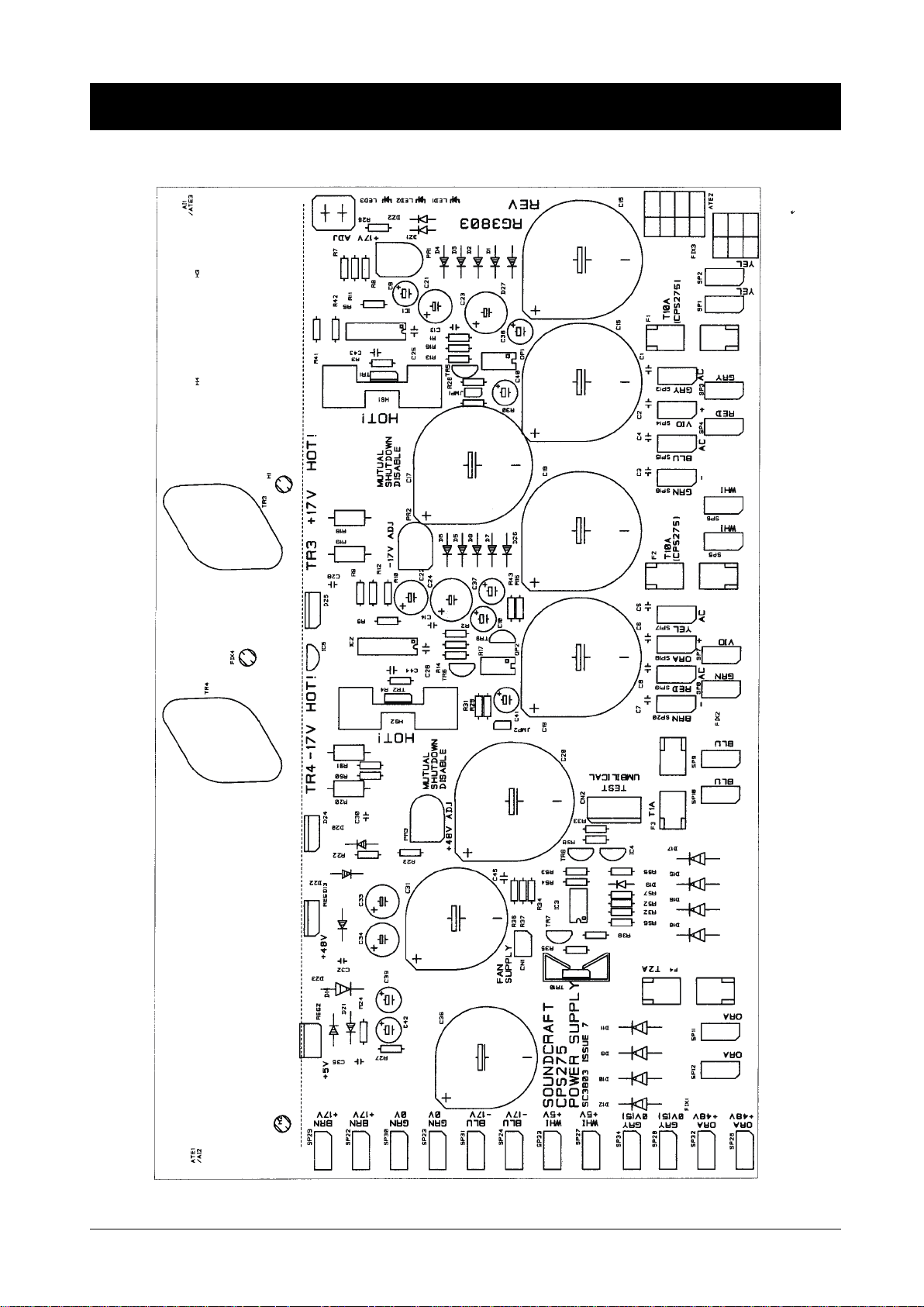
PCB Layout
20 Technical Description
Page 27
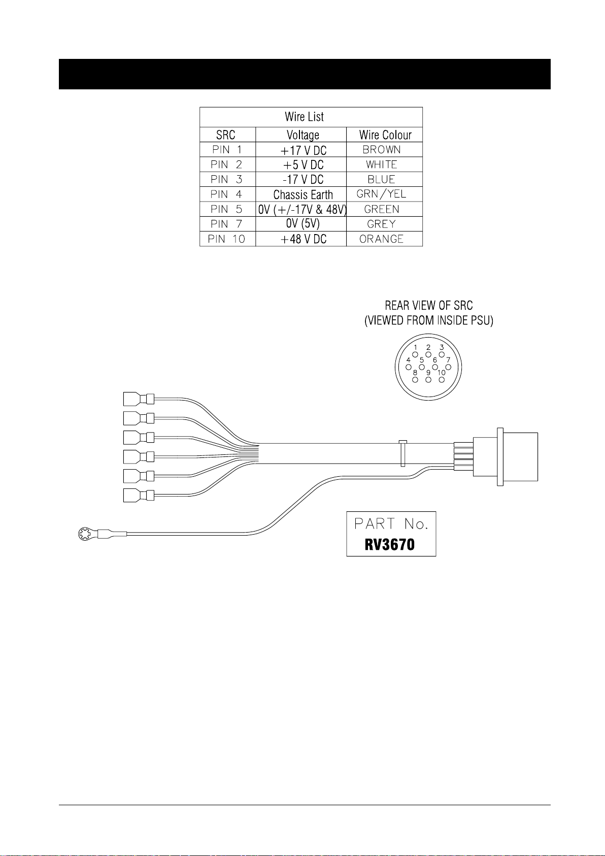
Output Pinouts
Technical Description 21
Page 28

22 Technical Description
Page 29

Parts List
Parts List 23
Page 30

Spare Parts
Notes:
1) The ’Module/PCB Assemblies’ section is indented to show those items which are part of another, higher level, item.
2) Some of the descriptions are followed by one of the following 3 symbols:
# - STATIC SENSITIVE. Anti-static precautions must be taken whilst handling this part.
! - SAFETY CRITICAL PART. A part of a different type may not be substituted.
@ - A part from a specific Manufacturer. Using an equivalent from another manufacturer may lead to loss of performance.
24 Parts List
Page 31

Top-Level Structures
CPS250 POWER SUPPLY UNIT RW8019
--- . . . . . . . . . . . . . . . . . . . . . . . . . . . . !NON ILL.RK SWT DPST(2600M11E) . . . . ! . . . . . DL8000
--- . . . . . . . . . . . . . . . . . . . . . . . . . . . . !IEC MAINS SKT 10A CPS250/275 . . . . . ! . . . . . FJ8029
--- . . . . . . . . . . . . . . . . . . . . . . . . . . . . CABLE TIE 4.3" . . . . . . . . . . . . . . . . . . . . . . . . LF0501
--- . . . . . . . . . . . . . . . . . . . . . . . . . . . . CABLE TIE BASE 19X19MM . . . . . . . . . . . . . . . . . LF0567
--- . . . . . . . . . . . . . . . . . . . . . . . . . . . . M4X8MM PAN POZI SCRW BLCK . . . . . . . . . . . . . . NA0241
--- . . . . . . . . . . . . . . . . . . . . . . . . . . . . NO6 X 5/8" TYPE B PAN POZI BLK . . . . . . . . . . . . . NA0258
--- . . . . . . . . . . . . . . . . . . . . . . . . . . . . M3X6 PN PZI W/CAPT WASHER ZNC . . . . . . . . . . . NA0401
--- . . . . . . . . . . . . . . . . . . . . . . . . . . . . M5 X 60MM HEX BOLT SET BLACK . . . . . . . . . . . . NA0420
--- . . . . . . . . . . . . . . . . . . . . . . . . . . . . NO8X3/8" CSK POZ BLK TYPE B . . . . . . . . . . . . . . NA0427
--- . . . . . . . . . . . . . . . . . . . . . . . . . . . . M4 NYLON INSERT NUT TYPE T . . . . . . . . . . . . . . NB0127
--- . . . . . . . . . . . . . . . . . . . . . . . . . . . . M5 S/PROOF WASHER . . . . . . . . . . . . . . . . . . . NC0217
--- . . . . . . . . . . . . . . . . . . . . . . . . . . . . M4 PLAIN STEEL WASHER ZNC CLR . . . . . . . . . . . NC0249
--- . . . . . . . . . . . . . . . . . . . . . . . . . . . . M4 BLACK PLASTIC WASHER . . . . . . . . . . . . . . . NC0250
--- . . . . . . . . . . . . . . . . . . . . . . . . . . . . M3X12.7MM THRD HEX SPACER . . . . . . . . . . . . . . ND0382
--- . . . . . . . . . . . . . . . . . . . . . . . . . . . . RIVET 1/8"X0.310" DOME HEAD . . . . . . . . . . . . . . NF0505
--- . . . . . . . . . . . . . . . . . . . . . . . . . . . . NYLON PLUG 25.5 DIA(LOCKING) . . . . . . . . . . . . . NZ2360
--- . . . . . . . . . . . . . . . . . . . . . . . . . . . . CPS250 POWER SUPPLY CHASSIS . . . . . . . . . . . . PH1400-01
--- . . . . . . . . . . . . . . . . . . . . . . . . . . . . CPS250/275 POWER SUPPLY LID . . . . . . . . . . . . . PJ1500-01
--- . . . . . . . . . . . . . . . . . . . . . . . . . . . . CPS250 ELEC MECH ASSY . . . . . . . . . . . . . . . . . RS5961
--- . . . . . . . . . . . . . . . . . . . . . . . . . . . . DCP200 LID EARTH WFM . . . . . . . . . . . . . . . . . . RV3491
--- . . . . . . . . . . . . . . . . . . . . . . . . . . . . CPS250 TRANSFORMER WFM . . . . . . . . . . . . . . . RV3666
--- . . . . . . . . . . . . . . . . . . . . . . . . . . . . CPS250/275 RECTIFIER WFM . . . . . . . . . . . . . . . . RV3668
--- . . . . . . . . . . . . . . . . . . . . . . . . . . . . CPS250/275 MAINS SWT WFM . . . . . . . . . . . . . . . RV3669
--- . . . . . . . . . . . . . . . . . . . . . . . . . . . . CPS275/250 DC OUTPUT WFM . . . . . . . . . . . . . . . RV3670
--- . . . . . . . . . . . . . . . . . . . . . . . . . . . . CPS250/275 CARTON . . . . . . . . . . . . . . . . . . . . TA0416
--- . . . . . . . . . . . . . . . . . . . . . . . . . . . . CPS250/275 CABLE TRAY . . . . . . . . . . . . . . . . . . TA0417
--- . . . . . . . . . . . . . . . . . . . . . . . . . . . . CPS250/275 FOAM ENDCAPS SET . . . . . . . . . . . . . TB0276
--- . . . . . . . . . . . . . . . . . . . . . . . . . . . . PSU EARTH SYMBOL SLF-ADH . . . . . . . . . . . . . . ZA0078
--- . . . . . . . . . . . . . . . . . . . . . . . . . . . . !5X20MM T6.3A/250V AS FUSE . . . . . . . ! . . . . . ZD8106
--- . . . . . . . . . . . . . . . . . . . . . . . . . . . . RICHO SCREW ON PLASTIC FEET . . . . . . . . . . . . . ZZ2541
CPS275 POWER SUPPLY UNIT RW8020
--- . . . . . . . . . . . . . . . . . . . . . . . . . . . . !NON ILL.RK SWT DPST(2600M11E) . . . . ! . . . . . DL8000
--- . . . . . . . . . . . . . . . . . . . . . . . . . . . . !IEC MAINS SKT 10A CPS250/275 . . . . . ! . . . . . FJ8029
--- . . . . . . . . . . . . . . . . . . . . . . . . . . . . CABLE TIE 4.3" . . . . . . . . . . . . . . . . . . . . . . . . LF0501
--- . . . . . . . . . . . . . . . . . . . . . . . . . . . . CABLE TIE BASE 19X19MM . . . . . . . . . . . . . . . . . LF0567
--- . . . . . . . . . . . . . . . . . . . . . . . . . . . . M4X8MM PAN POZI SCRW BLCK . . . . . . . . . . . . . . NA0241
--- . . . . . . . . . . . . . . . . . . . . . . . . . . . . NO6 X 5/8" TYPE B PAN POZI BLK . . . . . . . . . . . . . NA0258
--- . . . . . . . . . . . . . . . . . . . . . . . . . . . . M3X6 PN PZI W/CAPT WASHER ZNC . . . . . . . . . . . NA0401
--- . . . . . . . . . . . . . . . . . . . . . . . . . . . . M5 X 60MM HEX BOLT SET BLACK . . . . . . . . . . . . NA0420
--- . . . . . . . . . . . . . . . . . . . . . . . . . . . . NO8X3/8" CSK POZ BLK TYPE B . . . . . . . . . . . . . . NA0427
--- . . . . . . . . . . . . . . . . . . . . . . . . . . . . M4 NYLON INSERT NUT TYPE T . . . . . . . . . . . . . . NB0127
--- . . . . . . . . . . . . . . . . . . . . . . . . . . . . M5 S/PROOF WASHER . . . . . . . . . . . . . . . . . . . NC0217
--- . . . . . . . . . . . . . . . . . . . . . . . . . . . . M4 PLAIN STEEL WASHER ZNC CLR . . . . . . . . . . . NC0249
--- . . . . . . . . . . . . . . . . . . . . . . . . . . . . M4 BLACK PLASTIC WASHER . . . . . . . . . . . . . . . NC0250
--- . . . . . . . . . . . . . . . . . . . . . . . . . . . . M3X12.7MM THRD HEX SPACER . . . . . . . . . . . . . . ND0382
--- . . . . . . . . . . . . . . . . . . . . . . . . . . . . RIVET 1/8"X0.310" DOME HEAD . . . . . . . . . . . . . . NF0505
--- . . . . . . . . . . . . . . . . . . . . . . . . . . . . CPS275 POWER SUPPLY CHASSIS . . . . . . . . . . . . PH1401-01
--- . . . . . . . . . . . . . . . . . . . . . . . . . . . . CPS250/275 POWER SUPPLY LID . . . . . . . . . . . . . PJ1500-01
--- . . . . . . . . . . . . . . . . . . . . . . . . . . . . CPS275 ELEC MECH ASSY . . . . . . . . . . . . . . . . . RS5962
Parts List 25
Page 32

--- . . . . . . . . . . . . . . . . . . . . . . . . . . . . DCP200 LID EARTH WFM . . . . . . . . . . . . . . . . . . RV3491
--- . . . . . . . . . . . . . . . . . . . . . . . . . . . . CPS275 TRANSFORMER WFM . . . . . . . . . . . . . . . RV3667
--- . . . . . . . . . . . . . . . . . . . . . . . . . . . . CPS250/275 RECTIFIER WFM . . . . . . . . . . . . . . . . RV3668
--- . . . . . . . . . . . . . . . . . . . . . . . . . . . . CPS250/275 MAINS SWT WFM . . . . . . . . . . . . . . . RV3669
--- . . . . . . . . . . . . . . . . . . . . . . . . . . . . CPS275/250 DC OUTPUT WFM . . . . . . . . . . . . . . . RV3670
--- . . . . . . . . . . . . . . . . . . . . . . . . . . . . CPS250/275 CARTON . . . . . . . . . . . . . . . . . . . . TA0416
--- . . . . . . . . . . . . . . . . . . . . . . . . . . . . CPS250/275 CABLE TRAY . . . . . . . . . . . . . . . . . . TA0417
--- . . . . . . . . . . . . . . . . . . . . . . . . . . . . CPS250/275 FOAM ENDCAPS SET . . . . . . . . . . . . . TB0276
--- . . . . . . . . . . . . . . . . . . . . . . . . . . . . PSU EARTH SYMBOL SLF-ADH . . . . . . . . . . . . . . ZA0078
--- . . . . . . . . . . . . . . . . . . . . . . . . . . . . !5X20MM T6.3A/250V AS FUSE . . . . . . . ! . . . . . ZD8106
--- . . . . . . . . . . . . . . . . . . . . . . . . . . . . RICHO SCREW ON PLASTIC FEET . . . . . . . . . . . . . ZZ2541
26 Parts List
Page 33

Main Assemblies
--- CPS250 ELEC MECH ASSY RS5961
--- . . . . . . . . . . . . . . . . . . . . . . . . . . . . BDG RECT BR152 200V 15A . . . . . . . . . . . . . . . . BC0210
--- . . . . . . . . . . . . . . . . . . . . . . . . . . . . MJ15024 NPN POWER TRANS TO3 . . . . @ . . . . BD0373
REG1, . . . . . . . . . . . . . . . . . . . . . . . . . . VOLTAGE REG TL783CKC . . . . . . . . . . . . . . . . . BE0455
REG2, . . . . . . . . . . . . . . . . . . . . . . . . . . REG LM340AT 5.0V . . . . . . . . . . . . . . . . . . . . . BE0491
--- . . . . . . . . . . . . . . . . . . . . . . . . . . . . M5X30MM PAN POZI SCREW . . . . . . . . . . . . . . . . NA0094
REG1,2, . . . . . . . . . . . . . . . . . . . . . . . . . M3 X 8MM PAN POZI BLCK SCRW . . . . . . . . . . . . . NA0130
--- . . . . . . . . . . . . . . . . . . . . . . . . . . . . NO6X5/8 PAN CROSS REC B ZINC . . . . . . . . . . . . . NA0373
--- . . . . . . . . . . . . . . . . . . . . . . . . . . . . M5 NYLON INSERT NUT . . . . . . . . . . . . . . . . . . . NB0116
--- . . . . . . . . . . . . . . . . . . . . . . . . . . . . NYLOCK NUT ZINC 6-32 UNIFIED . . . . . . . . . . . . . NB0173
--- . . . . . . . . . . . . . . . . . . . . . . . . . . . . NO6 PLASTIC WASHER 1.58MM . . . . . . . . . . . . . . NC0295
--- . . . . . . . . . . . . . . . . . . . . . . . . . . . . FAN GASKET 80.00MM . . . . . . . . . . . . . . . . . . . NZ2357-02
--- . . . . . . . . . . . . . . . . . . . . . . . . . . . . CPS250/275 PSU HEATSINK . . . . . . . . . . . . . . . . PN1261-01
--- . . . . . . . . . . . . . . . . . . . . . . . . . . . . CPS250 PSU PCB ASSY . . . . . . . . . . . . . . . . . . . RC3803A
--- . . . . . . . . . . . . . . . . . . . . . . . . . . . . UNIVERSAL FAN WFM . . . . . . . . . . . . . . . . . . . . RV3142
REG1,2, . . . . . . . . . . . . . . . . . . . . . . . . . TIP INS BUSH . . . . . . . . . . . . . . . . . . . . . . . . . ZC0215
REG1,2, . . . . . . . . . . . . . . . . . . . . . . . . . KOOL PAD LM317T/337T . . . . . . . . . . . . . . . . . . ZC0217
--- . . . . . . . . . . . . . . . . . . . . . . . . . . . . 30CMX30CM THERMALLY CNDCTV SHT . . . . . . . . . ZC0223
--- . . . . . . . . . . . . . . . . . . . . . . . . . . . . KERATHERM 86/10 PAD . . . . . . . . . . . . . . . . . . . ZC0230
--- . . . . . . . . . . . . . . . . . . . . . . . . . . . . !FUSE COVER SCHURTER 853-9561 . . . . ! . . . . . ZD8013
F3 . . . . . . . . . . . . . . . . . . . . . . . . . . . . !5X20MM T1A/250V AS FUSE . . . . . . . . ! . . . . . ZD8101
F4 . . . . . . . . . . . . . . . . . . . . . . . . . . . . !5X20MM T2A/250V AS FUSE . . . . . . . . ! . . . . . ZD8102
F1, F2 . . . . . . . . . . . . . . . . . . . . . . . . . . !5X20MM T6.3A/250V AS FUSE . . . . . . . ! . . . . . ZD8106
--- CPS275 ELEC MECH ASSY RS5962
D24, D25 . . . . . . . . . . . . . . . . . . . . . . . . DIODE SCHOTTKY 10A 45V . . . . . . . . . . . . . . . . . BA0027
--- . . . . . . . . . . . . . . . . . . . . . . . . . . . . BDG RECT BR152 200V 15A . . . . . . . . . . . . . . . . BC0210
--- . . . . . . . . . . . . . . . . . . . . . . . . . . . . MJ15024 NPN POWER TRANS TO3 . . . . @ . . . . BD0373
REG1, . . . . . . . . . . . . . . . . . . . . . . . . . . VOLTAGE REG TL783CKC . . . . . . . . . . . . . . . . . BE0455
REG2, . . . . . . . . . . . . . . . . . . . . . . . . . . REG LM340AT 5.0V . . . . . . . . . . . . . . . . . . . . . BE0491
--- . . . . . . . . . . . . . . . . . . . . . . . . . . . . M5X30MM PAN POZI SCREW . . . . . . . . . . . . . . . . NA0094
--- . . . . . . . . . . . . . . . . . . . . . . . . . . . . M3 X 8MM PAN POZI BLCK SCRW . . . . . . . . . . . . . NA0130
--- . . . . . . . . . . . . . . . . . . . . . . . . . . . . NO6X5/8 PAN CROSS REC B ZINC . . . . . . . . . . . . . NA0373
--- . . . . . . . . . . . . . . . . . . . . . . . . . . . . M5 NYLON INSERT NUT . . . . . . . . . . . . . . . . . . . NB0116
--- . . . . . . . . . . . . . . . . . . . . . . . . . . . . NYLOCK NUT ZINC 6-32 UNIFIED . . . . . . . . . . . . . NB0173
--- . . . . . . . . . . . . . . . . . . . . . . . . . . . . M4 PLAIN STEEL WASHER ZNC CLR . . . . . . . . . . . NC0249
--- . . . . . . . . . . . . . . . . . . . . . . . . . . . . M4X9 1MM THICK RUBBER WASHER . . . . . . . . . . . NC0293
--- . . . . . . . . . . . . . . . . . . . . . . . . . . . . NO6 PLASTIC WASHER 1.58MM . . . . . . . . . . . . . . NC0295
--- . . . . . . . . . . . . . . . . . . . . . . . . . . . . M3.5 NYLON BUSH . . . . . . . . . . . . . . . . . . . . . . ND0392
--- . . . . . . . . . . . . . . . . . . . . . . . . . . . . FAN GASKET 80.00MM . . . . . . . . . . . . . . . . . . . NZ2357-02
--- . . . . . . . . . . . . . . . . . . . . . . . . . . . . CPS250/275 PSU HEATSINK . . . . . . . . . . . . . . . . PN1261-01
--- . . . . . . . . . . . . . . . . . . . . . . . . . . . . CPS275 PSU PCB ASSY . . . . . . . . . . . . . . . . . . . RC3803B
--- . . . . . . . . . . . . . . . . . . . . . . . . . . . . UNIVERSAL FAN WFM . . . . . . . . . . . . . . . . . . . . RV3142
--- . . . . . . . . . . . . . . . . . . . . . . . . . . . . TIP INS BUSH . . . . . . . . . . . . . . . . . . . . . . . . . ZC0215
--- . . . . . . . . . . . . . . . . . . . . . . . . . . . . KOOL PAD LM317T/337T . . . . . . . . . . . . . . . . . . ZC0217
--- . . . . . . . . . . . . . . . . . . . . . . . . . . . . 30CMX30CM THERMALLY CNDCTV SHT . . . . . . . . . ZC0223
--- . . . . . . . . . . . . . . . . . . . . . . . . . . . . KERATHERM 86/10 PAD . . . . . . . . . . . . . . . . . . . ZC0230
--- . . . . . . . . . . . . . . . . . . . . . . . . . . . . !FUSE COVER SCHURTER 853-9561 . . . . ! . . . . . ZD8013
F3 . . . . . . . . . . . . . . . . . . . . . . . . . . . . !5X20MM T1A/250V AS FUSE . . . . . . . . ! . . . . . ZD8101
F4 . . . . . . . . . . . . . . . . . . . . . . . . . . . . !5X20MM T2A/250V AS FUSE . . . . . . . . ! . . . . . ZD8102
F1, F2 . . . . . . . . . . . . . . . . . . . . . . . . . . !5X20MM T10A/250V AS FUSE . . . . . . . ! . . . . . ZD8110
Parts List 27
Page 34

Module/PCB Assemblies
--- CPS250 PSU PCB ASSY RC3803A
R22 . . . . . . . . . . . . . . . . . . . . . . . . . . . MF 0.25W RES 2% 82R . . . . . . . . . . . . . . . . . . . . AD0423
R34 . . . . . . . . . . . . . . . . . . . . . . . . . . . MF 0.25W RES 2% 150R . . . . . . . . . . . . . . . . . . . AD0429
R32 . . . . . . . . . . . . . . . . . . . . . . . . . . . MF 0.25W RES 2% 220R . . . . . . . . . . . . . . . . . . . AD0433
R3, R4 . . . . . . . . . . . . . . . . . . . . . . . . . . MF 0.25W RES 2% 270R . . . . . . . . . . . . . . . . . . . AD0435
R26 . . . . . . . . . . . . . . . . . . . . . . . . . . . MF 0.25W RES 2% 510R . . . . . . . . . . . . . . . . . . . AD0442
R1, R2 . . . . . . . . . . . . . . . . . . . . . . . . . . MF 0.25W RES 2% 1K . . . . . . . . . . . . . . . . . . . . AD0449
R15 . . . . . . . . . . . . . . . . . . . . . . . . . . . MF 0.25W RES 2% 1K6 . . . . . . . . . . . . . . . . . . . . AD0454
R13, R14 . . . . . . . . . . . . . . . . . . . . . . . . MF 0.25W RES 2% 2K2 . . . . . . . . . . . . . . . . . . . . AD0457
R25 . . . . . . . . . . . . . . . . . . . . . . . . . . . MF 0.25W RES 2% 2K7 . . . . . . . . . . . . . . . . . . . . AD0459
R35, R36, R37, R39, R40, R41
R42, R43, R50, R51, R52, R53
R54, R55 . . . . . . . . . . . . . . . . . . . . . . . . MF 0.25W RES 2% 3K3 . . . . . . . . . . . . . . . . . . . . AD0461
R23 . . . . . . . . . . . . . . . . . . . . . . . . . . . MF 0.25W RES 2% 3K9 . . . . . . . . . . . . . . . . . . . . AD0463
R5, R6, R7, R8, R9, R10 . . . . . . . . . . . . . . . . MF 0.25W RES 2% 4K7 . . . . . . . . . . . . . . . . . . . . AD0465
R30, R31 . . . . . . . . . . . . . . . . . . . . . . . . MF 0.25W RES 2% 6K8 . . . . . . . . . . . . . . . . . . . . AD0469
R11, R12, R24 . . . . . . . . . . . . . . . . . . . . . MF 0.25W RES 2% 7K5 . . . . . . . . . . . . . . . . . . . . AD0470
R16, R17, R28, R29 . . . . . . . . . . . . . . . . . . MF 0.25W RES 2% 100K . . . . . . . . . . . . . . . . . . . AD0497
R33 . . . . . . . . . . . . . . . . . . . . . . . . . . . W\W 4W 5% 33R . . . . . . . . . . . . . . . . . . . . . . . AH0739
R18, R19, R20, R21 . . . . . . . . . . . . . . . . . . W/W RES 4W 10% OR22 . . . . . . . . . . . . . . . . . . . AH0741
STD, . . . . . . . . . . . . . . . . . . . . . . . . . . . RES MF 10R 2% 0.25W RADIAL . . . . . . . . . . . . . . . AV0001
R46, R47, R48, R49 . . . . . . . . . . . . . . . . . . ZERO OHM RESISTOR (METAL SLUG) . . . . . . . . . . AZ2222
D21 . . . . . . . . . . . . . . . . . . . . . . . . . . . DIODE 1N4148 . . . . . . . . . . . . . . . . . . . . . . . . BA0001
D1, D2, D3, D4, D5, D6
D7, D8, D13, D14, D20 . . . . . . . . . . . . . . . . . DIODE 1N4001 . . . . . . . . . . . . . . . . . . . . . . . . BA0005
D9, D10, D11, D12, D15, D16
D17, D18 . . . . . . . . . . . . . . . . . . . . . . . . DIODE 1N5402 200V 3A PRFMD .6" . . . . . . . . . . . . BA0009
DZ1, DZ2 . . . . . . . . . . . . . . . . . . . . . . . . ZENER DIODE 400MW 9V1 . . . . . . . . . . . . . . . . . BB0105
DZ5 . . . . . . . . . . . . . . . . . . . . . . . . . . . ZENER DIODE 400MW 11V . . . . . . . . . . . . . . . . . BB0106
DZ3, DZ4 . . . . . . . . . . . . . . . . . . . . . . . . ZENER DIODE 400MW 15V . . . . . . . . . . . . . . . . . BB0107
TR5, TR6 . . . . . . . . . . . . . . . . . . . . . . . . NPN TRANS 2SC2240BL(TAPED) . . . . . . . . . . . . . . BD0302
TR1, TR2, TR7 . . . . . . . . . . . . . . . . . . . . . NPN TRANS BD135 . . . . . . . . . . . . . . . . . . . . . BD0317
OP1, OP2 . . . . . . . . . . . . . . . . . . . . . . . . CNY17-1 OPTO-COUPLER . . . . . . @ . . . . BD0348
IC1, IC2 . . . . . . . . . . . . . . . . . . . . . . . . . V.REG LM723 . . . . . . . . . . . . . . . . . . . . . . . . . BE0414
C25, C26 . . . . . . . . . . . . . . . . . . . . . . . . C/C0.2"TAPED 100V 470PF(N47) . . . . . . . . . . . . . . CA0008
C1, C2, C3, C4, C5, C6
C7, C8, C9, C10, C11, C12
C13, C14, C27, C28, C29, C30
C32, C35, C37, C38 . . . . . . . . . . . . . . . . . . POLY-CAP 5MM 5% 63V 100N . . . . . . . . . . . . . . . CC0252
C42 . . . . . . . . . . . . . . . . . . . . . . . . . . . VERT ELEC 0.2" TPD 47MF 25V . . . . . . . . . . . . . . CE0401
C33 . . . . . . . . . . . . . . . . . . . . . . . . . . . VERT ELEC 0.2" 47UF 63V . . . . . . . . . . . . . . . . . CE0402
C40, C41 . . . . . . . . . . . . . . . . . . . . . . . . VERT ELEC 0.2" TPD 100MF 10V . . . . . . . . . . . . . . CE0403
C31 . . . . . . . . . . . . . . . . . . . . . . . . . . . VERT ELEC 10MM 1000MF/100V . . . . . . . . . . . . . . CE0426
C21, C22, C34 . . . . . . . . . . . . . . . . . . . . . VERT ELEC 5MM 220MF/63V . . . . . . . . . . . . . . . . CE0429
C15, C16, C18, C19 . . . . . . . . . . . . . . . . . . VERT ELEC 10MM 10,000MF/35V . . . . . . . . . . . . . . CE0431
C39 . . . . . . . . . . . . . . . . . . . . . . . . . . . VERT ELEC 1000MF 6.3V . . . . . . . . . . . . . . . . . . CE0433
C23, C24 . . . . . . . . . . . . . . . . . . . . . . . . VERT ELEC 2200/25V 26X12MM . . . . . . . . . . . . . . CE0460
C36 . . . . . . . . . . . . . . . . . . . . . . . . . . . VERT ELEC 4700UF 35V 18X42MM . . . . . . . . . . . . . CE0481
PR1, PR2, PR3 . . . . . . . . . . . . . . . . . . . . . CERMET TRIMMER HORIZ 9OH 2K2 . . . . . . . . . . . . DE0401
CN1 . . . . . . . . . . . . . . . . . . . . . . . . . . . MTHD .1" 2WY VERT LCKNG ML HDR . . . . . . . . . . . FF0641
SP1,2,3 . . . . . . . . . . . . . . . . . . . . . . . . . 1/4" PC MNTNG BLADE VERT . . . . . . . . . . . . . . . FF0676
LED1,2, . . . . . . . . . . . . . . . . . . . . . . . . . MV5453 5MM GREEN LED DIFF . . . . . . . . . . . . . . . JA0065
D22, D23, D24, D25, STD . . . . . . . . . . . . . . . 0.6MM DIA RL TIN COPPER WIRE . . . . . . . . . . . . . LF0568A
28 Parts List
Page 35

H1, H2, TR3, TR3C, TR4, TR4C . . . . . . . . . . . . SELF CLINCHING FASTENER . . . . . . . . . . . . . . . . NZ2317
TR1, TR2 . . . . . . . . . . . . . . . . . . . . . . . . POWER STATION DRIVER HEATSINK . . . . . . . . . . . PN1241
--- . . . . . . . . . . . . . . . . . . . . . . . . . . . . CPS250/275 PSU PCB . . . . . . . . . . . . . . . . . . . . SC3803-03
LED1,2, . . . . . . . . . . . . . . . . . . . . . . . . . HOLDER FOR 5MM LED PC MNT . . . . . . . . . . . . . . ZC0222
TR1, TR2 . . . . . . . . . . . . . . . . . . . . . . . . DRIVER MOUNTING CLIP . . . . . . . . . . . . . . . . . . ZC0231
2 per f . . . . . . . . . . . . . . . . . . . . . . . . . . !SCHURTER FUSE CLIP . . . . . . . . . . . ! . . . . . ZD0317
--- CPS275 PSU PCB ASSY RC3803B
R22 . . . . . . . . . . . . . . . . . . . . . . . . . . . MF 0.25W RES 2% 82R . . . . . . . . . . . . . . . . . . . . AD0423
R34 . . . . . . . . . . . . . . . . . . . . . . . . . . . MF 0.25W RES 2% 150R . . . . . . . . . . . . . . . . . . . AD0429
R32 . . . . . . . . . . . . . . . . . . . . . . . . . . . MF 0.25W RES 2% 220R . . . . . . . . . . . . . . . . . . . AD0433
R3, R4 . . . . . . . . . . . . . . . . . . . . . . . . . . MF 0.25W RES 2% 270R . . . . . . . . . . . . . . . . . . . AD0435
R26 . . . . . . . . . . . . . . . . . . . . . . . . . . . MF 0.25W RES 2% 510R . . . . . . . . . . . . . . . . . . . AD0442
R1, R2 . . . . . . . . . . . . . . . . . . . . . . . . . . MF 0.25W RES 2% 1K . . . . . . . . . . . . . . . . . . . . AD0449
R15 . . . . . . . . . . . . . . . . . . . . . . . . . . . MF 0.25W RES 2% 1K6 . . . . . . . . . . . . . . . . . . . . AD0454
R13, R14 . . . . . . . . . . . . . . . . . . . . . . . . MF 0.25W RES 2% 2K2 . . . . . . . . . . . . . . . . . . . . AD0457
R25 . . . . . . . . . . . . . . . . . . . . . . . . . . . MF 0.25W RES 2% 2K7 . . . . . . . . . . . . . . . . . . . . AD0459
R35, R36, R37, R39, R40, R41
R42, R43, R50, R51, R52, R53
R54, R55 . . . . . . . . . . . . . . . . . . . . . . . . MF 0.25W RES 2% 3K3 . . . . . . . . . . . . . . . . . . . . AD0461
R23 . . . . . . . . . . . . . . . . . . . . . . . . . . . MF 0.25W RES 2% 3K9 . . . . . . . . . . . . . . . . . . . . AD0463
R5, R6, R7, R8, R9, R10 . . . . . . . . . . . . . . . . MF 0.25W RES 2% 4K7 . . . . . . . . . . . . . . . . . . . . AD0465
R30, R31 . . . . . . . . . . . . . . . . . . . . . . . . MF 0.25W RES 2% 6K8 . . . . . . . . . . . . . . . . . . . . AD0469
R11, R12, R24 . . . . . . . . . . . . . . . . . . . . . MF 0.25W RES 2% 7K5 . . . . . . . . . . . . . . . . . . . . AD0470
R16, R17, R28, R29 . . . . . . . . . . . . . . . . . . MF 0.25W RES 2% 100K . . . . . . . . . . . . . . . . . . . AD0497
R18, R19, R20, R21 . . . . . . . . . . . . . . . . . . W/W RES 4W 10% OR22 . . . . . . . . . . . . . . . . . . . AH0741
OPA, . . . . . . . . . . . . . . . . . . . . . . . . . . RES MF 10R 2% 0.25W RADIAL . . . . . . . . . . . . . . . AV0001
R38 . . . . . . . . . . . . . . . . . . . . . . . . . . . ZERO OHM RESISTOR (METAL SLUG) . . . . . . . . . . AZ2222
D21 . . . . . . . . . . . . . . . . . . . . . . . . . . . DIODE 1N4148 . . . . . . . . . . . . . . . . . . . . . . . . BA0001
D1, D2, D3, D4, D5, D6
D7, D8, D13, D14, D20 . . . . . . . . . . . . . . . . . DIODE 1N4001 . . . . . . . . . . . . . . . . . . . . . . . . BA0005
D9, D10, D11, D12, D15, D16
D17, D18 . . . . . . . . . . . . . . . . . . . . . . . . DIODE 1N5402 200V 3A PRFMD .6" . . . . . . . . . . . . BA0009
D23 . . . . . . . . . . . . . . . . . . . . . . . . . . . DIODE SCHOTTKY 3A 20V IN5820 . . . . . . . . . . . . . BA0028
D22 . . . . . . . . . . . . . . . . . . . . . . . . . . . DIODE SCHOTTKY 1.1A 60V 11DQ06 . . . . . . . . . . . BA0029
DZ1, DZ2 . . . . . . . . . . . . . . . . . . . . . . . . ZENER DIODE 400MW 9V1 . . . . . . . . . . . . . . . . . BB0105
DZ5 . . . . . . . . . . . . . . . . . . . . . . . . . . . ZENER DIODE 400MW 11V . . . . . . . . . . . . . . . . . BB0106
DZ3, DZ4 . . . . . . . . . . . . . . . . . . . . . . . . ZENER DIODE 400MW 15V . . . . . . . . . . . . . . . . . BB0107
TR5, TR6 . . . . . . . . . . . . . . . . . . . . . . . . NPN TRANS 2SC2240BL(TAPED) . . . . . . . . . . . . . . BD0302
TR1, TR2, TR7 . . . . . . . . . . . . . . . . . . . . . NPN TRANS BD135 . . . . . . . . . . . . . . . . . . . . . BD0317
OP1, OP2 . . . . . . . . . . . . . . . . . . . . . . . . CNY17-1 OPTO-COUPLER . . . . . . @ . . . . BD0348
IC1, IC2 . . . . . . . . . . . . . . . . . . . . . . . . . V.REG LM723 . . . . . . . . . . . . . . . . . . . . . . . . . BE0414
C25, C26 . . . . . . . . . . . . . . . . . . . . . . . . C/C0.2"TAPED 100V 470PF(N47) . . . . . . . . . . . . . . CA0008
C1, C2, C3, C4, C5, C6
C7, C8, C9, C10, C11, C12
C13, C14, C27, C28, C29, C30
C32, C35, C37, C38 . . . . . . . . . . . . . . . . . . POLY-CAP 5MM 5% 63V 100N . . . . . . . . . . . . . . . CC0252
C42 . . . . . . . . . . . . . . . . . . . . . . . . . . . VERT ELEC 0.2" TPD 47MF 25V . . . . . . . . . . . . . . CE0401
C33 . . . . . . . . . . . . . . . . . . . . . . . . . . . VERT ELEC 0.2" 47UF 63V . . . . . . . . . . . . . . . . . CE0402
C40, C41 . . . . . . . . . . . . . . . . . . . . . . . . VERT ELEC 0.2" TPD 100MF 10V . . . . . . . . . . . . . . CE0403
C31 . . . . . . . . . . . . . . . . . . . . . . . . . . . VERT ELEC 10MM 1000MF/100V . . . . . . . . . . . . . . CE0426
C21, C22, C34 . . . . . . . . . . . . . . . . . . . . . VERT ELEC 5MM 220MF/63V . . . . . . . . . . . . . . . . CE0429
C15, C16, C17, C18, C19, C20 . . . . . . . . . . . . VERT ELEC 10MM 10,000MF/35V . . . . . . . . . . . . . . CE0431
C39 . . . . . . . . . . . . . . . . . . . . . . . . . . . VERT ELEC 1000MF 6.3V . . . . . . . . . . . . . . . . . . CE0433
C36 . . . . . . . . . . . . . . . . . . . . . . . . . . . VERT ELEC 4700MF/50V(22MM DIA) . . . . . . . . . . . . CE0450
C23, C24 . . . . . . . . . . . . . . . . . . . . . . . . VERT ELEC 2200/25V 26X12MM . . . . . . . . . . . . . . CE0460
PR1, PR2, PR3 . . . . . . . . . . . . . . . . . . . . . CERMET TRIMMER HORIZ 9OH 2K2 . . . . . . . . . . . . DE0401
Parts List 29
Page 36

CN1 . . . . . . . . . . . . . . . . . . . . . . . . . . . MTHD .1" 2WY VERT LCKNG ML HDR . . . . . . . . . . . FF0641
SP1,2,3 . . . . . . . . . . . . . . . . . . . . . . . . . 1/4" PC MNTNG BLADE VERT . . . . . . . . . . . . . . . FF0676
LED1,2, . . . . . . . . . . . . . . . . . . . . . . . . . MV5453 5MM GREEN LED DIFF . . . . . . . . . . . . . . . JA0065
OPA, . . . . . . . . . . . . . . . . . . . . . . . . . . 0.6MM DIA RL TIN COPPER WIRE . . . . . . . . . . . . . LF0568A
H1, H2, TR4, H4C, H3, H3C . . . . . . . . . . . . . . SELF CLINCHING FASTENER . . . . . . . . . . . . . . . . NZ2317
TR1, TR2 . . . . . . . . . . . . . . . . . . . . . . . . POWER STATION DRIVER HEATSINK . . . . . . . . . . . PN1241
--- . . . . . . . . . . . . . . . . . . . . . . . . . . . . CPS250/275 PSU PCB . . . . . . . . . . . . . . . . . . . . SC3803-03
LD1, LD2, LD3 . . . . . . . . . . . . . . . . . . . . . HOLDER FOR 5MM LED PC MNT . . . . . . . . . . . . . . ZC0222
TR1, TR2 . . . . . . . . . . . . . . . . . . . . . . . . DRIVER MOUNTING CLIP . . . . . . . . . . . . . . . . . . ZC0231
F1, F2, F3, F4 . . . . . . . . . . . . . . . . . . . . . . !SCHURTER FUSE CLIP . . . . . . . . . . . ! . . . . . ZD0317
30 Parts List
Page 37

Page 38

 Loading...