

Soundcraft B800 BROCHURE

SOUNDCRAFT
User Guide

© Harman International Industries Ltd. 1995, 1996
All rights reserved
Parts of the design of this product may be protected by worldwide patents.
Part No. ZM0117
Issue 4
Soundcraft is a trading division of Harman International Industries Ltd.
Information in this manual is subject to change without notice an d does not represe nt
a commitment on the part of the vendor. Soundcraft shall not be liable for loss or
damage whatsoever arising from the use of information or any erro r contained in this
manual.
No part of this manual may be reproduced, stored in a retrieval system, or tra nsmitted,
in any form or by any means, electronic, electrical, mechanical, optical, chemical,
including photocopying and recording, for any purpose without the express written
permission of Soundcraft.
It is recommended that all maintenance and service on the product should be carried
out by Soundcraft or its authorised agents. Soundcraft cannot accept any liability
whatsoever for any loss or damage caused by service, maintenance or repair by
unauthorised personnel.
Harman International Industries Limited.
Cranborne House,
Cranborne Road,
Cranborne Industrial Estate,
Potters Bar,
Herts.,
EN6 3JN
UK.
Tel: 01707 665000
Fax: 01707 660482

7DEOHRI&RQWHQWV
1.Introduction 1.1
Introduction 1.2
Warranty 1.3
2. Installation 2.1
Dimensions 2.2
Meterbridge 2.3
EDAC Connectors 2.4
Rear Connector Panel D-type Connectors 2.6
Jumper Options 2.8
Internal Monitor Source Selection 2.12
3. Block Diagrams 3.1
Mono Input Block Diagram 3.2
Group Module Block Diagram 3.3
Stereo Input Block Diagram 3.4
Stereo Group Module Block Diagram 3.5
ST1 /ST2 Master Block diagram 3.6
Monitor Block Diagram 3.7
Comms Block Diagram 3.8
4. Functional Description 4.1
Mono Input Module 4.2
Stereo Input Module 4.8
Mono Group Module 4.14
Stereo Group Module 4.18
i

Master ST1 & ST2 Modules 4.22
Monitor Module 4.26
Communication Module 4.30
Meterbridge Modules 4.34
5.Specifications 5.1
ii

1.Introduction
B800 Introduction 1.1

,QWURGXFWLRQ
B800
Congratulations on purchasing a Soundcraft console. The B8 00 ha s b ee n design ed
to meet today’s needs of Live TV & Radio Broadcast and Production Facilities
including OB vehicles.
System Features
The B800 features:
• 5 frame sizes: 24, 32, 40, 48 and 56 module-widths are available.
• 8 Mono Groups (or 4 Stereo Groups).
• 2 Stereo Master Outputs.
• 6 Mono Auxes & 2 Stereo Auxes.
• Stereo AFL/PFL
• 4 VCA Groups
Power Supply
The B800 uses the CPS275 Power Supply.
1.2 B800 Introduction

:DUUDQW\
1 Soundcraft is a trading division of Harman International Industries Ltd .
End User means the person who first puts the equipment into regular operation.
Dealer means the person other than Soundcraft (if any) from whom the End
User purchased the Equipment, provided such a person is authorised for this
purpose by Soundcraft or its accredited Distributor.
Equipment means the equipment supplied with this ma nua l.
2 If within the period of twelve months from the date of delivery of the Equipment
to the End User it shall prove defective by reason only of faulty materials and/or
workmanship to such an extent that the effectiveness and/or usability thereof is
materially affected the Equipment or the defective compone nt should be re tu rn ed
to the Dealer or to Soundcraft and subject to the following conditions the Dealer
or Soundcraft will repair or replace the defective components. Any components
replaced will become the property of Soundcraft.
3 Any Equipment or component returned will be at the risk of the End User whilst in
transit (both to and from the Dealer or Soundcraft) and postage must be prepaid.
4 This warranty shall only be ava ila ble if:
a) the Equipment has been properly installed in accordance with instructions
contained in Soundcraft’s manual; and
b) the End User has notified Soundcraft or the Dealer within 14 days of the
defect appearing; and
c) no persons other than authorised representatives of Soundcraft or the Dealer
have effected any replacement of parts maintenance adjustments or repairs to the
Equipment; and
d) the End User has used the Equipment only for such purposes as Soundcraft
recommends, with only such operating supplies as meet Soundcraft’s
specifications and otherwise in all respects in accordance Soundcraft’s
recommendations.
5 Defects arising as a result of the following are not covered by this Warranty: faulty
or negligent handling, chemical or electro-chemical or electrical influences,
accidental damage, Acts of God, neglect, deficiency in electrical power,
air-conditioning or humidity control.
6. The benefit of this Warranty may not be assigned by the End User.
7. End Users who are consumers should note their rights under this Warranty are in
addition to and do not affect any other rights to which they may be entitled
against the seller of the Equipment.
B800 Introduction 1.3

1.4 B800 Introduction

2. Installation
B800 Installation 2.1
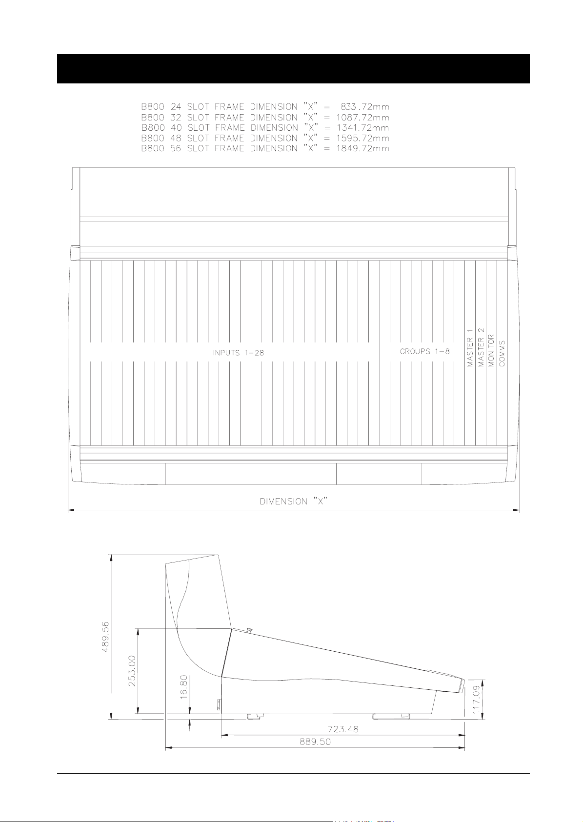
'LPHQVLRQV
2.2 B800 Installation

(DUWKLQJ7KH&RQVROH
Important Notice.
0HWHUEULGJH
The console has two earth posts on the rear c onnec to r pane l. They are loc ate d ne ar
to the power supply connectors. The un-insulated metal post is the chassis ground,
and the insulated post is the system ground. The co nsole is supplied with these two
posts linked together. It is essential that the console is ope rated with these two earths
linked. They may, however, be linked at a different point in the installation: for
example, a technical earth in the installation site . In this case the wire link between
the two posts must be removed.
The meterbridge has a number of connectors as shown below.
The MONITOR/COMMS D-type connector routes signals to the Monitor Se lector
PCB ( see the Meterbridge connector list on the previous page fo r pin details).
The ANCILLARY METERS D-type connector carries the Groups and Auxes into
the meterbridge. The actual connections used will depend on the number of a ncillary
meters which are fitted. The connections are:
1 Gnd 14 Gnd
2 Group8 15 Group7
3 Group6 16 Group5
4 Group4 17 Group3
5 Group2 18 Group1
6 Not Used 19 Not Used
7 Not Used 20 Not Used
8 Aux1 21 Aux2
9 Aux3 22 Aux4
10 Aux5 23 Aux6
11 Aux7L 24 Aux7R
12 Aux8L 25 Aux8R
13 Not Used
The EXTERNAL INPUTS XLRs are also routed to the Monitor Selector PCB.
The inputs here may be monitored on the Meters which are associated with the
Monitor Selector PCB.
There are also 2 additional XLRs. The first of this is commonly used to connect the
T/B Mic feed from the meterbridge to the T/Binput in the console, via the XLR on
the flying lead. The second XLR is for future expansion.
B800 Installation 2.3
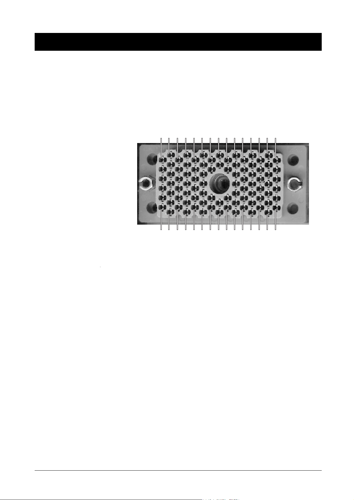
5HDU&RQQHFWRU3DQHO('$&&RQQHFWRUV
There are two 90-way EDAC’s associated with the master section. Viewed from
the rear of the console, EDAC1is to the right of EDAC2. These 2 EDAC’s have the
functions described on the next pages. Other EDACs on the console may be for
stereo group and stereo channel outputs, and wiring information for these will be
specified to each console and is therefore supplied separately. These EDAC
receptacles, often known as fe male, have pins which are surrounded by a protruding
plastic moulding. The photograph below shows the pin labelling (as viewed from
the outside of the console).
AHRXAEAMAVAZBDBJBSBYCFCNCW
FWADAUAYBCBHBRBXCECMCVDB AL P
The pins are listed in circuits below - the circuit functions for each EDAC are shown
on the following pages.
HI (+) LO (-) GND
CCT 1 A B C
CCT 2 H J K
CCT 3 R S T
CCT 4 X Y Z
CCT 5 AE AF AH
CCT 6 AM AN AP
CCT 7 BJ BK BL
CCT 8 BS BI BU
CCT 9 BY BZ CA
CCT 10 CF CH CJ
CCT 11 CN CP CR
CCT 12 CW CX CY
CCT 13 F E D
CCT 14 P N M
CCT 15 W V U
CCT 16 AD AC AB
CCT 17 AL AK AJ
CCT 18 AU AT AS
CCT 19 BR BP BN
CCT 20 BX BW BV
CCT 21 CE CD CC
CCT 22 CM CL CK
CCT 23 CV CU CT
CCT 24 DB PA CZ
2.4 B800 Installation

:D\('$&'HWDLOV
EDAC 1
Circuit Number Function
CCT 1 not used
CCT 2 Ext Cue I/P
CCT 3 Prod T/B I/P
CCT 4 T/B to Ext
CCT 5 Oscillator L
CCT 6 Oscillator0 R
CCT 7 Ext Mon I/P L
CCT 8 Ext Mon I/P R
CCT 9 Stud Spkr L
CCT 10 Stud Spkr R
CCT 11 PH1L Studio
CCT 12 PH1R Studio
CCT 13 T/B to opt 1
CCT 14 T/B to opt 2
CCT15 Ext 1L
CCT16 Ext 1R
CCT17 Ext 2L
CCT18 Ext 2R
CCT19 Ext 3L
CCT20 Ext 3R
CCT21 Ext 4L
CCT22 Ext 4R
CCT 23 PH2L Guest
CCT 24 PH2R Guest
EDAC 2
Circuit Number Function
CCT 1 Mono 2
CCT 2 Aux 2
CCT 3 Aux 4
CCT 4 Aux 6
CCT 5 Aux 8 L
CCT 6 Aux 8 R
CCT 7 Ext 5L
CCT 8 Ext 5R
CCT 9 Ext 6L
CCT 10 Ext 6R
CCT 11 Ext 7L
CCT 12 Ext 7R
CCT13 RTN T/B
CCT14 T/B Line Output
CCT 15 ST1L
CCT 16 ST1R
CCT 17 Mono 1
CCT 18 Aux 1
CCT 19 Aux 3
CCT 20 Aux 5
CCT 21 Aux 7L
CCT 22 Aux 7R
CCT 23 Ext 8L
CCT 24 Ext 8R
B800 Installation 2.5

5HDU&RQQHFWRU3DQHO'W\SH&RQQHFWRUV
There are a number of 25-way D-type female connectors (depending upon the number of input channels) on the rear
connector panel. The diagram below shows a typical view of those which are located at the bottom edge of the rear
connector panel.
CH1-4CH9-12CH17-20CH25-28GRP5-8
CH5-8CH13-16CH21-24GRP1-4ST1 & ST2
The diagram below shows the pin labelling (as viewed from the outside of the console).
113
1425
The pin-outs of the various D-types are given below.
Remote 25-way D-types
Pin Function Pin Function
Channel 4 (8) (12) (16) (20) (24) (28) (GRP4) (GRP8)
1 EXT MUTE (
active low
) 14 VCA CTL (
0V=0dB, 5V= -
∞
)
2 STOP #2(n/o relay contact) 15 STOP#1(n/o relay contact)
3 REMOTE START#2 (n/o relay contact) 16 REMOTE START#1(n/o relay contact)
Channel 3 (7) (11) (15) (19) (23) (27) (GRP3) (GRP7)
4 EXT MUTE 17 VCA CTL
5 STOP#2(n/o relay contact) 18 STOP #1(n/o relay contact)
6 REMOTE START#2 (n/o relay contact) 19 REMOTE START#1(n/o relay contact)
Channel 2 (6) (10) (14) (18) (22) (26) (GRP2) (GRP6) (ST2)
7 EXT MUTE 20 VCA CTL
8 STOP #2(n/o relay contact) 21 STOP #1(n/o relay contact)
9 REMOTE START #2(n/o relay contact) 22 REMOTE START#1(n/o relay contact)
Channel 1 (5) (9) (13) (17) (21) (25) (GRP1) (GRP5) (ST1)
10 EXT MUTE 23 VCA CTL
11 STOP #2(n/o relay contact) 24 STOP #1(n/o relay contact)
12 REMOTE START #2(n/o relay contact) 25 REMOTE START #1(n/o relay contact)
13 not used
Notes: GRP & ST Master modules do not utilise the "stop" function.
The remaining 2 sections of the ST1& ST2 connector are not connected.
Ground Ref. for EXT MUTE and VCA CTL is on EXT LOGIC D-type connector.
2.6 B800 Installation

EXT LOGIC
Pin Function Pin Function
1 GND 14 GND
2 GND 15 Prod T/B Stud CTL
3 Prod T/B to Ext CTL (I/P) 16 Mic Open (active low )
4 Prod T/B to Eng CTL (I/P) 17 Talk to Ext CTL O/P
5 Option 2 - CTL #2 / CF2 18 Option 2 - CTL #1 / CF2
6 Option 1 - CTL #2 / CF1 19 Option 1 - CTL #1 / CF1
7 On-Air o/p # 20 On-Air O/P #2
8 On-Air i/p #1 21 On-Air I/P #2
9 Not Used 22 Not Used
10 Ext Mntr (Level CTL I/P) 23 Ext CUE (Level CTL I/P)
11 RET T/B CTL (I/P) 24 Ext A/B CTL R (I/P)
12 Ext A/B CTL L (I/P) 25 Ext mute R (I/P)
13 Ext mute L (I/P)
METERBRIDGE
This connects via a ribbon cable to the Monitor/Comms D-type on the meterbridge.
1 ST1Left 14 ST1Right
2 ST2Left 15 ST2Right
3 MONO1 16 MONO2
4 Not used 17 Not used
5 Not used 18 Not used
6 Not Used 19 GND
7 Not Used 20 TB Mic +1V5
8 Studio Right 21 Studio Left
9 Ext VCA Warning LED 22 Monitor Left
10 Monitor Right 23 O/Press Signal
11 O/Press Ctl 24 Squawk Feed
12 Cue Meter Right 25 Cue Left
13 Cue Ctl
B800 Installation 2.7

-XPSHU2SWLRQV
MONO INPUT
* = DEFAULT
Note:Internal switch SW22 and Links 1 to 4 operate in conjunction with
each other.
SW22 Released = Insert Point is Pre-fade (see links 1 to 4)
Depressed= Insert Point is Post-fade (links 1 to 4 have
no effect, but they must be present)
LK1-4 Pre-fade Insert 1-2 = Pre Eq,
2-3 = Post Eq*
J1 Fit for VCA Option
J2 VCA GND 1-2 = Local *
2-3 Master 0V
J3 Remote Start 1-2 Pulse start/stop *
2-3 latched on-off
J4 Remote Start SW 1-2 . Omit Diode D10*
fit 2-3 for no REMOTE START SW
J5 Remote Start 1-2 = Start pulses only.
SW Function 2-3 = Latching start/stop *
J6 * Omit for meter cal
J7 Stereo Auxes 1-2 Pre-mute*
2-3 Post-mute
J8 Mono Auxes 1-2 Pre Mute
2-3 Post Mute *
J9 Slate/Cleanfeed 1-2 makes these mutually exclusive.
2-3 interactive*
J10 Meter feed 1-2 Pre EQ
2-3 Pre Fade (post mute)*
J11 Remote Common 1-2 Remote.
2-3 Local *
J12 Signalisation 1-2 Monitor Dim.
2-3 Studio Mute*
J13 Signalisation 1-2 Line Input only.
2-3 Mic Input only*
J14 Meter Feed 1-2 Meter Feed is ’Aux1 to Direct O/P’
2-3 Meter follows J10 setting
J15 Direct Output 1-2 Direct O/P is PRE Mute
2-3 Direct O/P is AFL
J16 Remote Start 1-2 Remote Start is active only in LINE mode
2-3 Remote Start is active only in MIC
2.8 B800 Installation

MONO GRP
J1 Rem Com A = local *
3 pin B = rem com
J2 FIT = t/b replaces prog ( to grp o/p )*
2 pin OMIT = t/b mix with prog
J3 FIT = slate replaces prog*
2 pin OMIT = slate mix with prog
J4 A = On Air does not kill T/B to GRP O/P *
3 pin B = On Air kills T/B to GRP O/P
J5 A= Limiter Affects St feed & GRP to GRP routing
3 pin B= Limiter Bypass for St ETC limit on GRP O/P
J6 FIT = Pre-emphasis on limit side chain *
2 pin omit = no pre-emphasis)
J7 Mono aux A = Pre mute
3 pin B = post mute*
J8 St Aux 7/8 A = Pre mute*
3 pin B = Post mute
only *
J9 - J13 Not Used
S30 = INT Insert Pre/post SW *= Pre-Fade
STEREO GRP
J1 Rem Com 1-2 = local *
3 pin 2-3 = rem com
J2 FIT = t/b replaces prog ( to grp o/p )*
2 pin OMIT = t/b mix with prog
J3 FIT = slate replaces prog*
2 pin OMIT = slate mix with prog
J4 1-2 = On Air does not kill T/B to GRP O/P *
3 pin 2-3 = On Air kills T/B to GRP O/P
J5 Left 1-2= Limiter Affects St feed & GRP to GRP routing
3 pin 2-3= Limiter Bypass for St ETC limit on GRP O/P only*
J7 Right 1-2= Pre mute
3 pin 2-3 = post mute*
J9 , J10 St Aux 7/8 1-2 = Pre fader
3 pin 2-3= Pre mute
J11, J12 Mono sum 1-2 =Pre fader
for Aux1-6 2-3=Pre Mute
J13 to J17 Not Used
B800 Installation 2.9

Note:Internal switches SW27 & SW28 and Links 1 to 8 operate in
conjunction with each other.
SW27 Released = Insert Point is Pre-fade (see links 1 to 8)
& SW28 Depressed = Insert Point is Post-fade (links 1 to 8 have
no effect, but they must be present)
LK1-8 Pre-fade Insert 1-2 = Pre Eq,
2-3 = Post Eq*
LK9 &10 set the input to the meter rectifier.
Pre-EQ 1-2
Pre-fader 2-3 *
J7 & J8 set the mono ’pre’ feed to the auxes
Pre-mute 1-2*
Pre-fade 2-3
The following jumpers are on the sub-PCB.
J3 REM START 1-2 Pulse start/stop *
2-3 latched on-off
J4 REM SW 1-2 . Omit Diode D45 *
fit 2-3 for no REM SW
J5 REM SW FUNC 1-2 = Start pulses only.
2-3 = Latching start/stop *
J11 REM COM 1-2 Remote.
2-3 local *
J12 Signalisation 1-2 Monitor Dim.
2-3 Studio Mute*
J10 Signalisation 1-2 Line Input only.
STEREO MASTER
J1 Rem Com 3 pin A= Local *
J2 - J3 Not Used
J4 2 pin Fit = T/B Replace prog *
J5 & J6 Fit = Limiter pre-emphasis
Option Single VCA Ctl fader (only)
2-3 Mic Input only*
B = REM
Omit = T/B Mix Prog
Omit = No pre emphasis *
or Stereo Audio fader or 2 Mono faders.
2.10 B800 Installation

MONITOR MODULE
J1 1-2 *
J2/J3/J4 1-2 * Cue to Monitor
J5/J6/J7/J8/J9 1-2 *
J10 & J11
If the Q Speaker Outputs are not being used, link J10 pins 1 to 2, and
link J11 pins 1 to 2. In this configuration, a sum of the Cue Left and
Right Signals are routed to the Cue Speaker on the Overbridge. This
feed is muted by using the Overpress facility (if it is fitted).
If the Q Speaker Outputs are being used, link J10 pin1 to J11 pin1,
and link J10 pin 2 to J11 pin 2. In this configuration the sum of the
Cue Left and Cue Right signals is never routed to the Cue Speaker on
the Overbridge. The individual Cue Left and Cue Right signals are
routed to their respective Cue Speaker Outputs, but these are muted
by using the Overpress facility (if it is fitted). Alternatively if only pins
J10 pin2 and J11 pin 2 are linked then the Overpress facility will not
mute the Cue L & R signals to the Cue Speaker Outputs.
2-3 ’Ext 8’ Input is -10dBV sensitivity
2-3 Talk to Studio (used with used with
2 monitor modules as C/room /Studio)
2-3 Prod T/B to Studio (used with used with
2 monitor modules as C/room /Studio)
J12 1-2 * Cue mixes with H/phone prog
2-3 Cue replaces H/phone prog
J13 1-2* for monitor dim by DIM bus
2-3 for monitor mute by dim bus
J14 1-2 * Studio Mute
2-3 fit for use as a Studio Monitor Module
Dim range is adjustable from 0 to -30dB by preset pot VR7.
COMMS MODULE
J1 & J2 1 & 2 linked on both jumpers
Signal from EXT CUE on Comms Module EDAC
are routed by released OPT 1 And OPT 2
switches to the T/B to OPT1 and the T/B to
OPT2 outputs on the Comms Module EDAC
Pins 2 & 3 linked on both jumpers =
EXT CUE signal not routed.
J3 T/B to Studio Speakers
1- 2 * Mute kills T/B to Spkrs
2- 3 T/B overrides Mute
J4 1-2 * T/B mixes with prog
2 - 3 T/B replaces prog (& Prod T/B)
J5 & 6 2-3 fitted *
T/B line input level is set by preset VR8
Dim range is adjustable from 0 to -30dB by preset VR15
B800 Installation 2.11
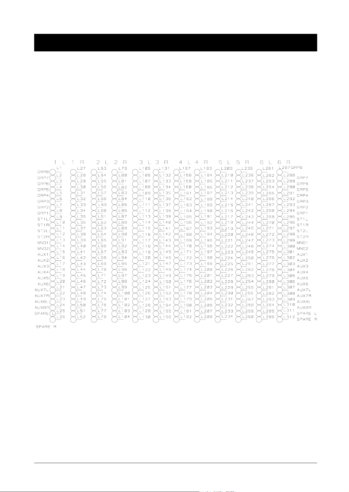
,QWHUQDO0RQLWRU6RXUFH6HOHFWLRQ
The DESK ’A’ bank of switches, on the Monitor Module, allows you to sele ct 1 of 6 internal signals as the internal monitor
source. The 6 are selected via th e scramble card (SC3556) in the console . The a ppropriate section of this PCB’s silk scree n
is reproduced below. The six signals may be chosen from the following list:
•
Group 1 to Group 8 ( Group 1 toGroup 4 L + R for Sterero Group )
•
The Main Stereo Mixes of the ST1 and the ST2 Modules
•
The Mono Mixes of the ST1 and the ST2 Modules
•
Aux1 to Aux8.
There is also a spare left and spare right feed which may be used to monitor any suitable point in the console.
Fitting Links
Suitably sized hair-pin links may be soldered into the appropriate thro ugh-plated holes. T ake care to select the correct side
when connecting a stereo pair. For example, if you wanted to assign Source 1 to Aux 6 then you would fit links L20 and
L46. If you then wanted to assign Source 2 to Aux 7 (which is a stereo pair) then you would fit links L73 and L100.
The factory default setting is:
Left Right
Source 1 ST1 L ST1 R
Source 2 ST2 L ST2 R
Source 3 GP1 / ( GP1L ) GP2 / ( GP1R )
Source 4 GP3 / ( GP2L ) GP4 / ( GP2R )
Source 5 GP5 / ( GP3L ) GP6 / ( GP3R )
Source 6 GP7 / ( GP4L ) GP8 / ( GP4R )
2.12 B800 Installation

3. Block Diagrams
B800 Block Diagrams 3.1
 Loading...