

Page 1

Working Instruction, Mechanical
Working Instruction, Mechanical
Applicable for W850i
CONTENTS
1 Introduction .............................................................................. 3
1.1 Equipment.................................................................................4
1.2 General cautions ...................................................................... 5
1.3 Adhesives .................................................................................5
1.4 Recurrent Repair Actions ........................................................ 5
2 Disassembly ............................................................................. 6
2.1 Overview ...................................................................................6
2.1.1 Battery Cover Assembly and Battery..................................... 7
2.1.2 Upper Rear Lid Assembly .....................................................8
2.1.3 Upper Front Assembly Complete ..........................................9
2.1.4 Dividing the Phone into Upper and Lower half’s.................. 11
2.1.5 Numeric Key Foil assembly................................................. 15
2.1.6 Lower Rear Cover Assembly (and Main PBA) ....................16
2.1.7 ESD Protection Sheet .........................................................17
2.1.8 LCD Module and Navigation Key Foil Assembly ................. 18
2.1.9 Lower Front Assembly, Upper Carrier Assembly and Slide
Mechanism.......................................................................... 19
3 Replacements......................................................................... 21
3.1 Battery Cover..........................................................................22
3.2 Upper Rear Lid Assembly......................................................22
3.3 Upper Front Assembly Complete .........................................22
3.4 Numeric Key Foil Assembly..................................................22
3.5 Lower Rear Cover assembly ................................................. 22
3.6 ESD Protection Sheet ............................................................22
3.7 LCD Module ............................................................................22
3.8 Navigation Key Foil Assembly..............................................23
3.9 Lower Front Assembly, Upper Carrier Assembly and Slide
Mechanism..............................................................................23
3.10 External Antenna Plug Assembly.........................................24
3.11 IRDA Window..........................................................................25
3.12 Co-Brand Label....................................................................... 26
3.13 Tape Upper Rear Lid .............................................................. 27
3.14 Rubber Connector, Speaker Plate ........................................28
3.15 Keyboard Navigation .............................................................29
3.16 Ear Speaker............................................................................. 30
3.17 Water Indicator ....................................................................... 32
3/000 21-1/FEA 209 544/104 C
Company Internal
© Sony Ericsson Mobile Communications AB
Page 2

Working Instruction, Mechanical
3.18 Duo Lid ....................................................................................33
3.19 Keyboard Numeric .................................................................34
3.20 Microphone Grommet ............................................................ 35
3.21 Microphone .............................................................................36
3.22 Camera Key............................................................................. 37
3.23 Conductive Gasket.................................................................38
3.24 Tape for Slider Mechanism....................................................39
3.25 Damper for Lower Front (1) ................................................... 40
3.26 Damper for Lower Front (2) ................................................... 41
3.27 VGA Camera Gasket ..............................................................42
3.28 Camera Module (VGA) With Flex ..........................................43
3.29 Half- Half Flex with Components .......................................... 45
3.30 Adhesive Half to Half .............................................................46
3.31 Main Flex Assembly ............................................................... 47
3.32 Lower Damper for Upper Carrier Assembly ........................49
3.33 Protective Tape, Test Points ................................................. 50
3.34 Vibrator.................................................................................... 51
3.35 Volume Keys...........................................................................52
3.36 On/Off Key............................................................................... 53
3.37 BT Antenna .............................................................................54
3.38 System Connector..................................................................55
3.39 Dust Gasket, System Connector...........................................56
3.40 Insulation Label ...................................................................... 57
3.41 Flash Reflector .......................................................................58
3.42 LED-Flash Assembly..............................................................59
3.43 Loud Speaker Box Assembly................................................60
3.44 Camera Rubber....................................................................... 62
3.45 Shield Can Camera Module ................................................... 63
3.46 Camera Module 2M FF ........................................................... 64
3.47 LCD Tape................................................................................. 66
3.48 Slide Mechanism Protection Tape........................................67
3.49 Label 68
4 Reassembly ............................................................................ 69
4.1 Overview .................................................................................69
4.1.1 Upper Carrier Assembly, Slide Mechanism and Lower Front
Assembly............................................................................. 70
4.1.2 LCD Module Assembly and Navigation Key Foil Assembly. 73
4.1.3 ESD Protection Sheet .........................................................75
4.1.4 Lower Rear Cover Assembly (and Main PBA) ....................76
4.1.5 Reassembly of the Phones Upper and Lower half’s............77
Together with the Numeric Key Foil Assembly................................. 77
4.1.6 Upper Front Assembly Complete ........................................81
4.1.7 Upper Rear Lid Assembly ...................................................83
4.1.8 Battery and Battery Cover ................................................... 85
5 Revision history ..................................................................... 87
3/000 21-1/FEA 209 544/104 C
© Sony Ericsson Mobile Communications AB
2(87)
Page 3
Working Instruction, Mechanical
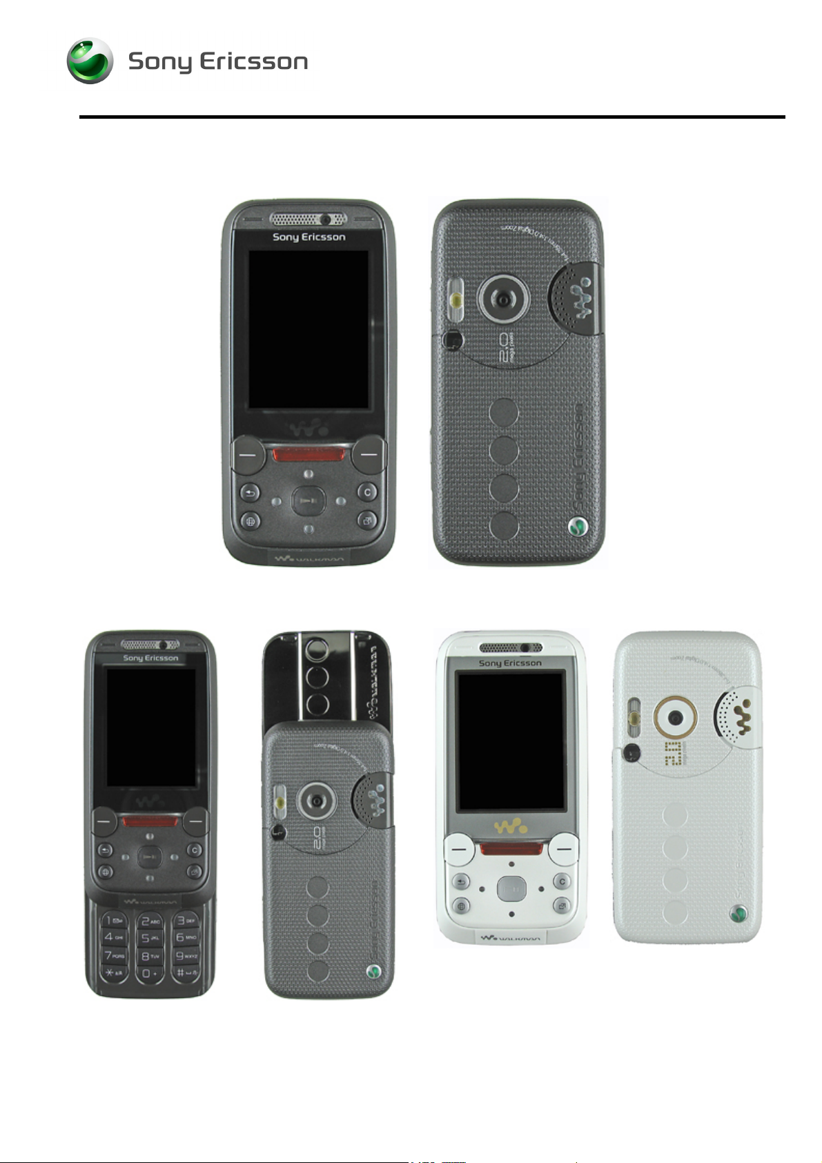
1 Introduction
W850i Black
W850i Black W850i White
3/000 21-1/FEA 209 544/104 C
Company Internal
© Sony Ericsson Mobile Communications AB
Page 4
Working Instruction, Mechanical
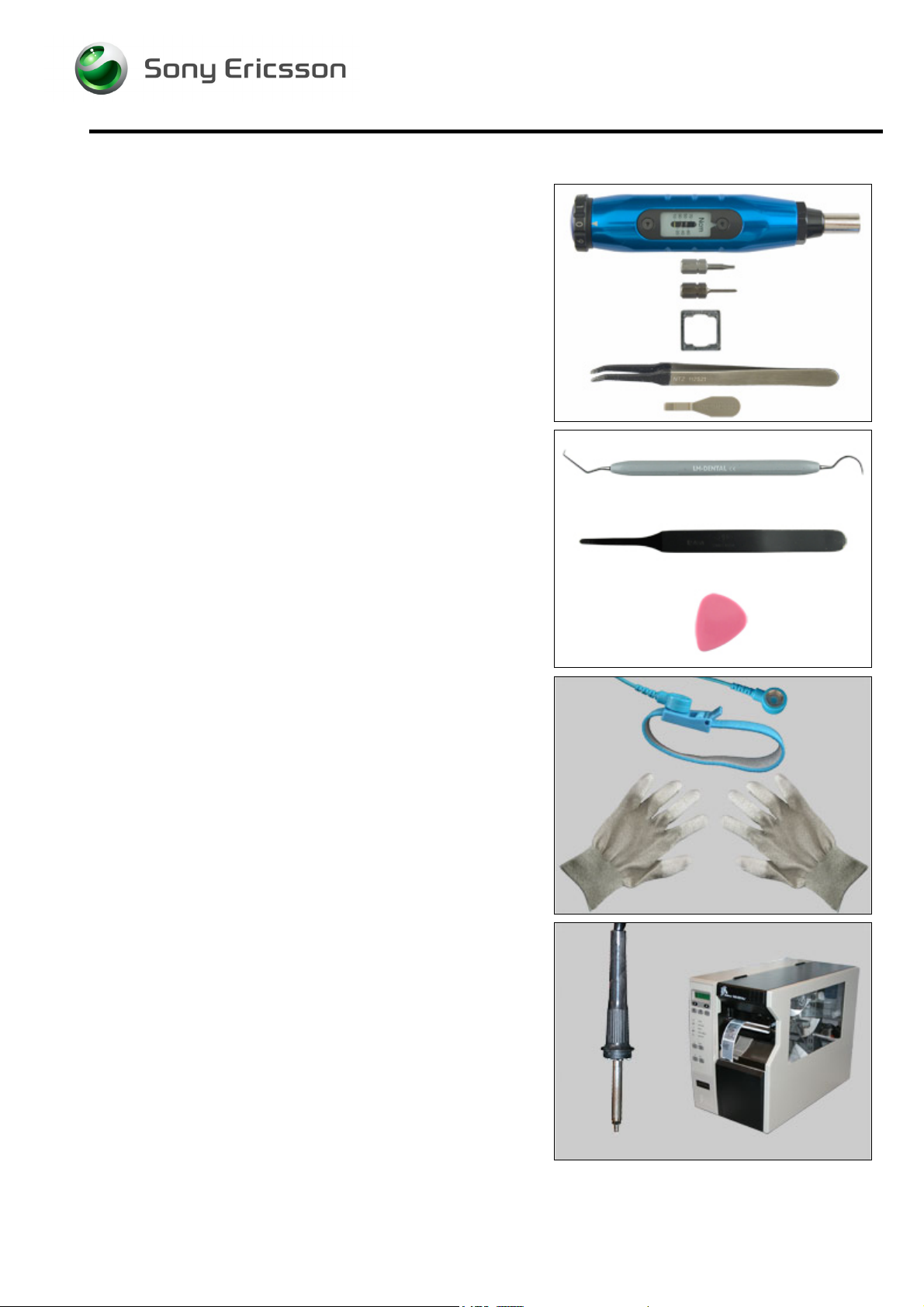
1.1 Equipment
SPECIAL TOOLS
Requirements (no new tools):
• NTZ 112 459 Torque screwdriver (or equivalent)
• NTZ 112 288 Torx bit no. 6
• NTZ 112 1052 JCIS bit
• NTZ 112 1067 Camera tool
• NTZ 112 521 Flex film assembly tool
• NTZ 112 302/2 Front opening tool (Black or beige)
STANDARD TOOLS
The following tools have to be locally purchased:
• Dentist hook
• Blunt pair of tweezers
• Guitar pick
ESD EQUIPMENT
Protect the phone from ESD damages whenever it has
been opened by using:
• ESD-wristband
• ESD-gloves
LABEL EQUIPMENT
The following special equipment is required when replacing
or installing a new label:
• Hot air flow solder station
• Zebra printer connected to computer
3/000 21-1/FEA 209 544/104 C
Company Internal
© Sony Ericsson Mobile Communications AB
Page 5
Working Instruction, Mechanical
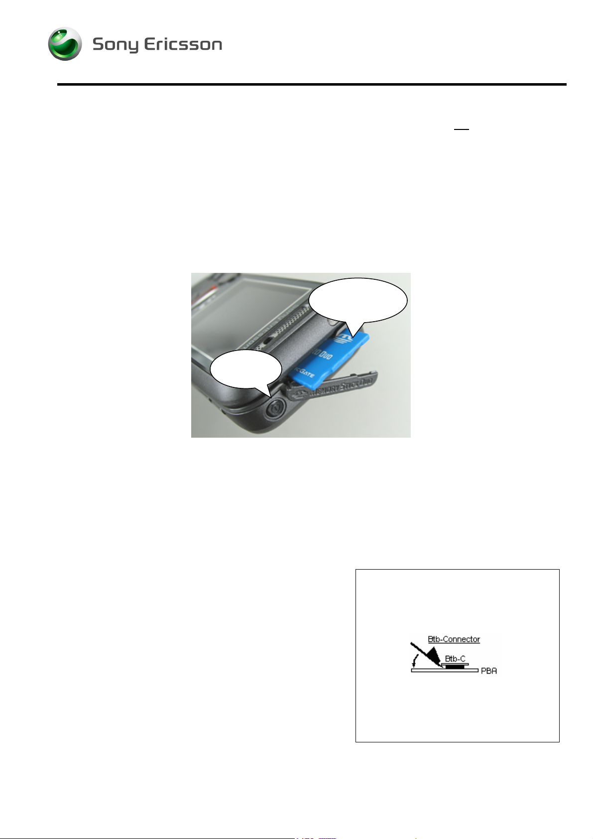
1.2 General cautions
The following cautions are considered to be generic for all phone models and will not be repeated in
the Disassembly, Replacements and Reassembly sections:
• S
WITCH OFF THE PHONE AND REMOVE ANY MEMORY STICK BEFORE THE START OF THE DISASSEMBLY!
• K
EEP ALL CONTACT SURFACES CLEAN!
• B
E CAREFUL WHEN USING TOOLS LIKE THE DENTIST HOOK, TWEEZERS, OPENING TOOLS, GUITAR PICK
ETC. TO AVOID SCRATCHES OR DAMAGES TO THE EXTERIOR AND INTERIOR PARTS OF THE PHONE!
E CAREFUL NOT TO DAMAGE ANY CONTACT SPRINGS!
• B
• R
EMEMBER TO REMOVE THE PROTECTION FOILS ON NEW PARTS SUCH AS THE FRONT COVER AND LCD!
• N
EVER TOUCH THE DISPLAY GLASS!
SE AIR BLOW EQUIPMENT TO KEEP THE FRONT WINDOW AND DISPLAY MODULE DUST FREE!
• U
Remove the
memory stick!
Switch off
the phone!
1.3 Adhesives
Use a dentist hook and/or the tweezers to remove old adhesives.
Clean the surface with isopropyl alcohol before attaching new adhesives.
1.4 Recurrent Repair Actions
How to open a board-to-board connector with the front
opening tool.
3/000 21-1/FEA 209 544/104 C
Company Internal
© Sony Ericsson Mobile Communications AB
Page 6
Working Instruction, Mechanical
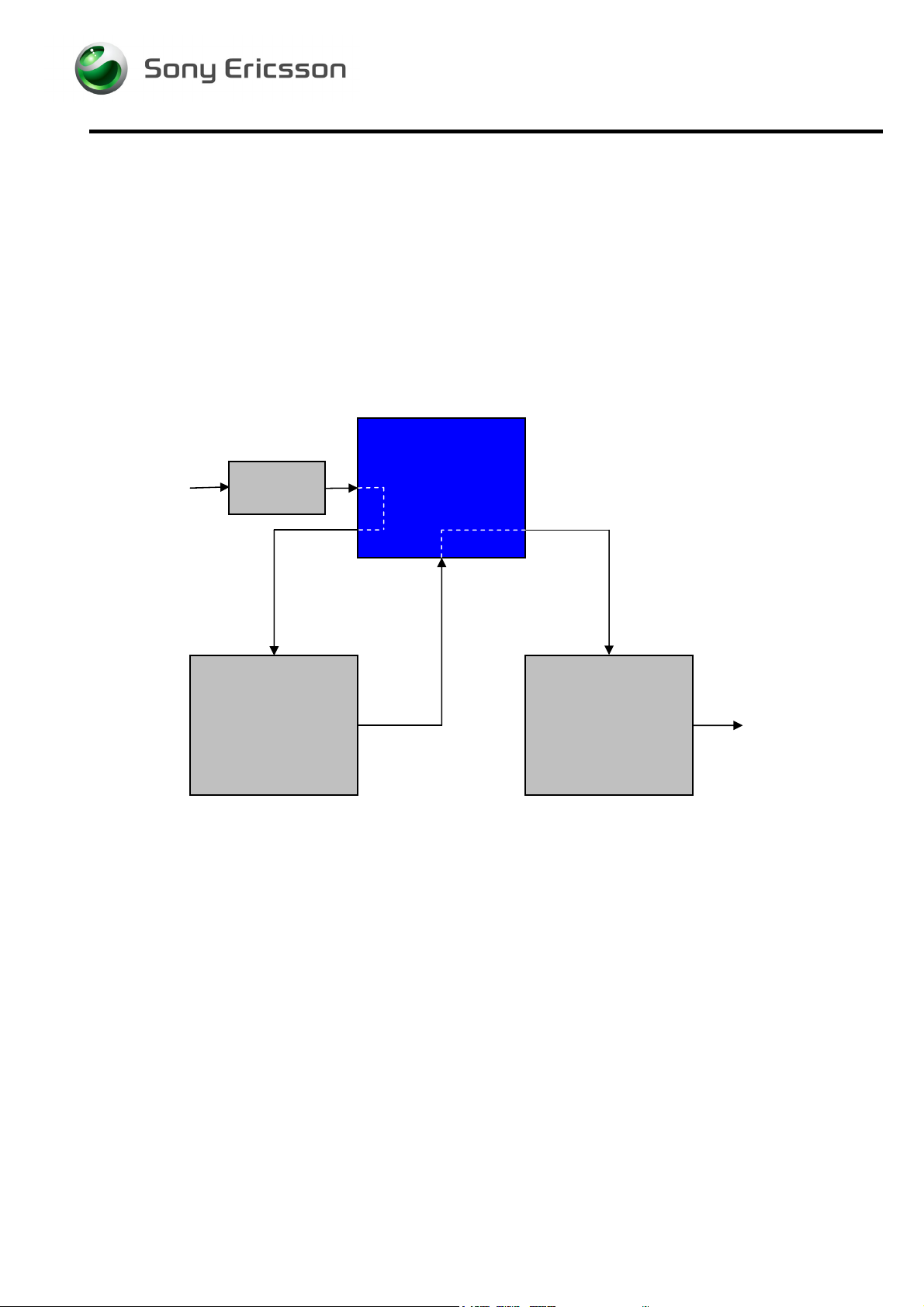
2 Disassembly
When you are going to replace a part being listed in Replacements, the instruction of that section
usually begins by directing you to this Disassembly section with a specification of the instructions you
have to carry out in order to disassemble the phone as far as needed before returning to
Replacements for the actual replacement.
REPLACEMENTS
Start
Contents
page
DISASSEMBLY
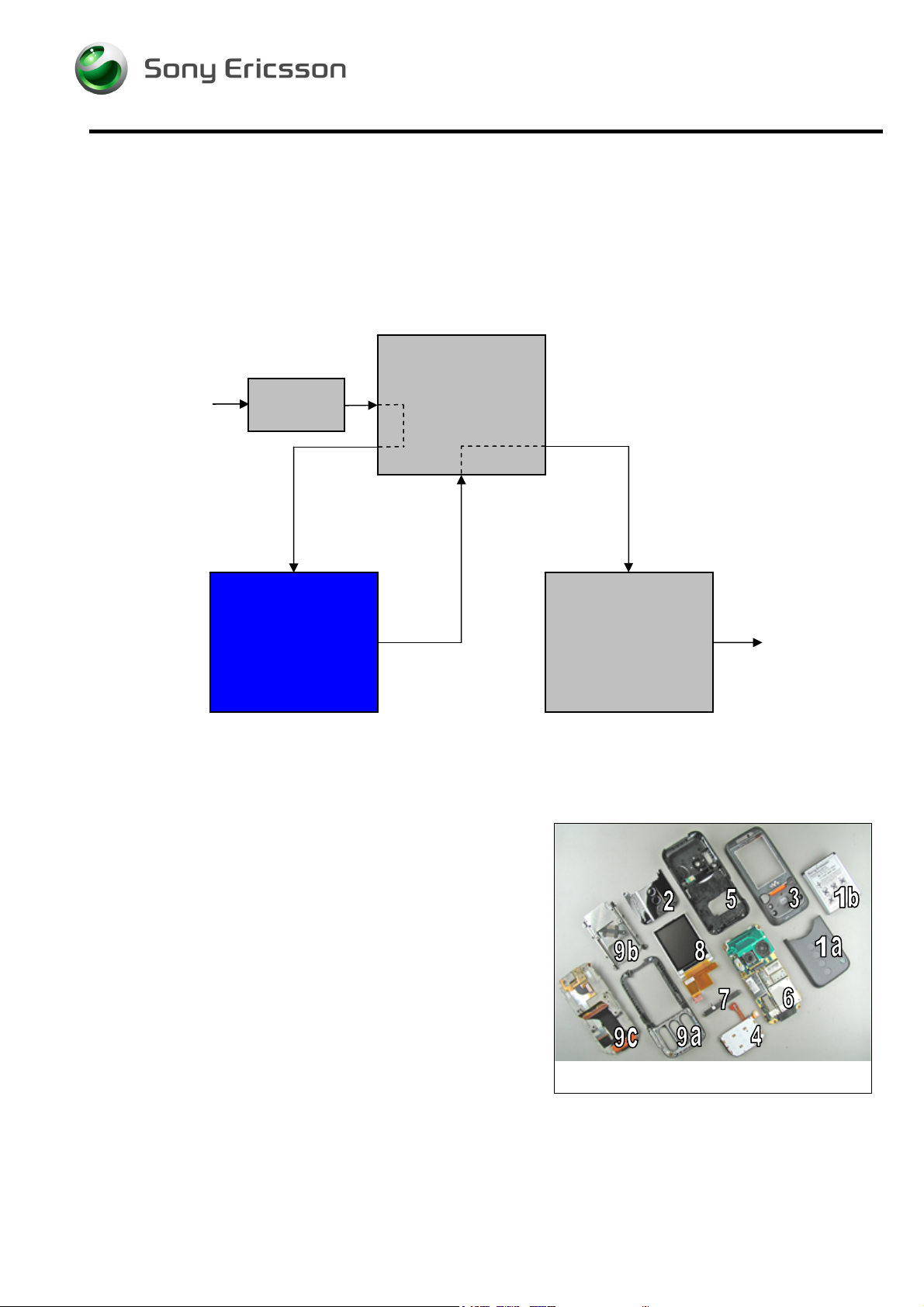
2.1 Overview
The disassembly is done in the following sequence:
1. Battery Cover (a) and Battery (b)
2. Upper Rear Lid
3. Upper Front Assembly Complete
4. Numeric Key Foil Assembly
5. Lower Rear Cover Assembly
6. Main PBA
7. ESD Protection Sheet
8. LCD Module Assembly
9. Lower Front Assembly (a), Slide Mechanism (b) and
Upper Carrier Assembly (c)
REASSEMBLY
Done
3/000 21-1/FEA 209 544/104 C
Company Internal
© Sony Ericsson Mobile Communications AB
Page 7
Working Instruction, Mechanical
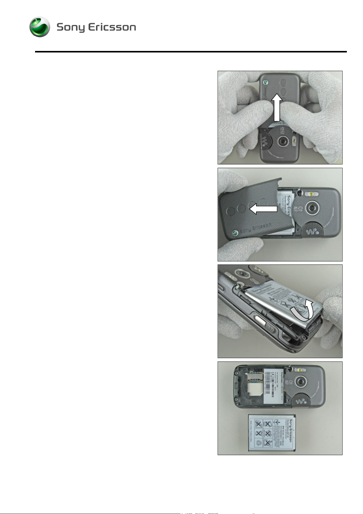
2.1.1 Battery Cover Assembly and Battery
Press with your thumbs (sometimes quite hard) on the
battery cover assembly until you get a gap.
Remove the battery cover assembly.
Start to remove the battery from the phone with your
fingers. Lift up the battery in the bottom end to unleash it.
If not released, turning the phone around at the same time
will make it become released.
Remove the battery completely from the phone with your
fingers.
3/000 21-1/FEA 209 544/104 C
Company Internal
© Sony Ericsson Mobile Communications AB
Page 8
Working Instruction, Mechanical
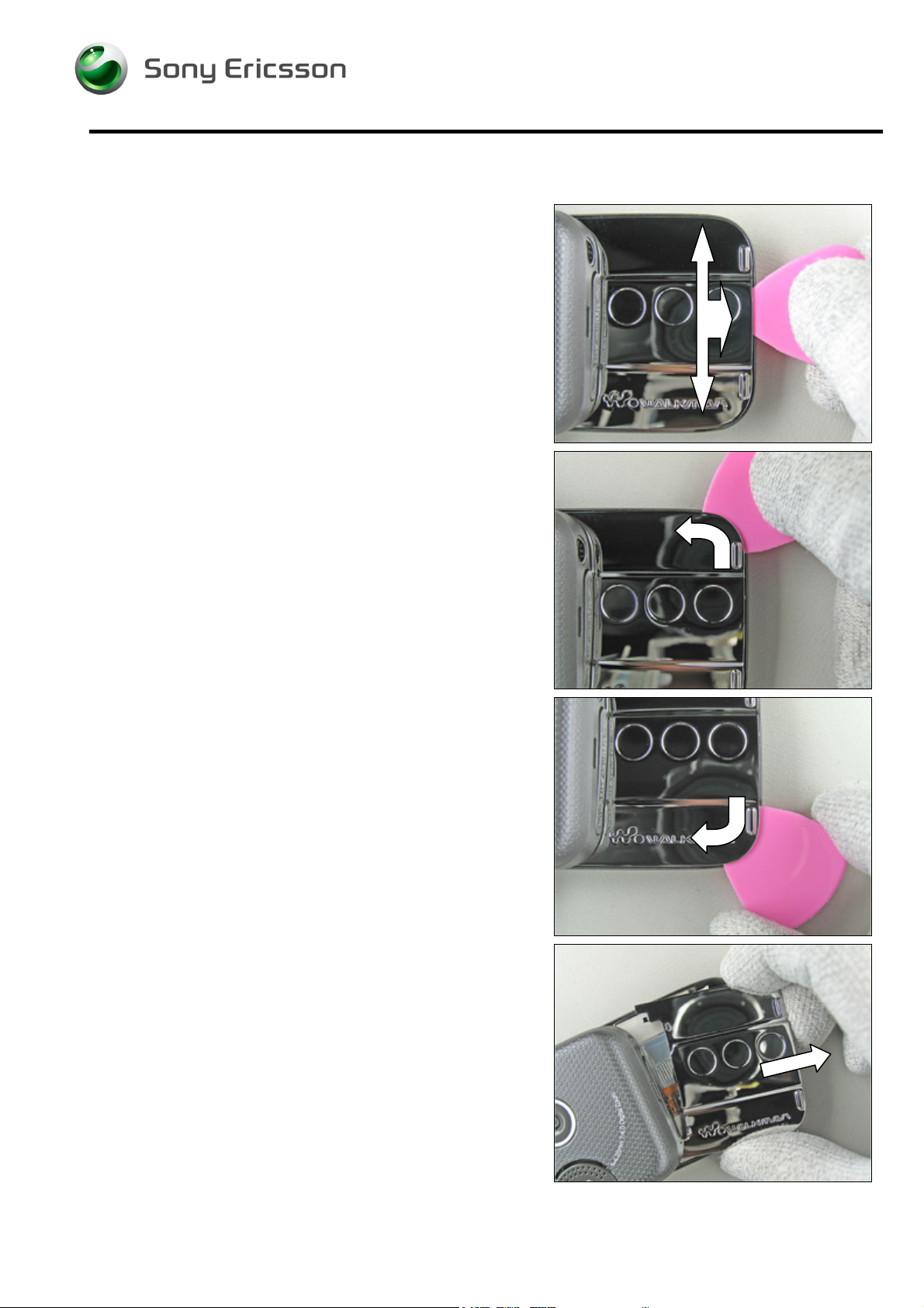
2.1.2 Upper Rear Lid Assembly
DO NOT INSERT THE GUITAR PICK TO DEEP INTO THE PHONE!
Carefully insert the guitar pick in the middle of the upper
rear lid assembly.
Continue to gently bend until the lid starts to become loose
from the upper front assembly complete.
Move the plectrum along the gap (around the corner) until
the lid is loose on this side.
Continue and do the same thing on the other side.
Remove the upper rear lid assembly completely.
3/000 21-1/FEA 209 544/104 C
Company Internal
© Sony Ericsson Mobile Communications AB
Page 9
Working Instruction, Mechanical
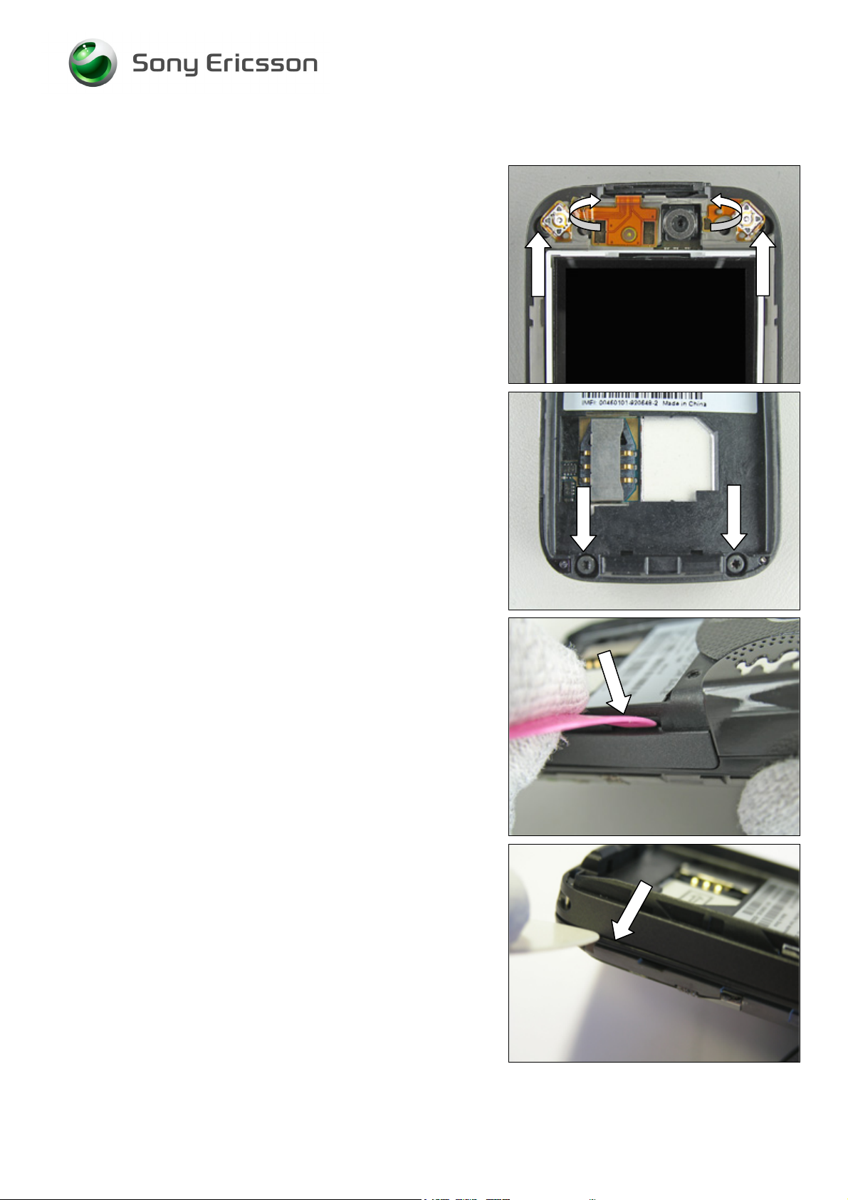
2.1.3 Upper Front Assembly Complete
Remove the two inside screws from the upper carrier
assembly by using the NTZ 112 288 (torx bit no 6).
Replace the screw if it’s damaged otherwise it can be
reused.
Use the front opening tool to bend and make the upper front
assembly complete to start to become loose.
BE CAREFUL NOT TO BREAK THE FRONT!
Continue to bend further down on the upper front assembly
complete until it’s loose on this side.
Start on the opposite side and do the same thing.
3/000 21-1/FEA 209 544/104 C
© Sony Ericsson Mobile Communications AB
9(87)
Page 10
Working Instruction, Mechanical
Disassembly Instruction continued
BE CAREFUL NOT TO BREAK THE FRONT!
And again.
Gently fold down the upper front assembly complete and
remove it.
Disassembled upper front assembly complete.
3/000 21-1/FEA 209 544/104 C
© Sony Ericsson Mobile Communications AB
10(87)
Page 11
eused
Working Instruction, Mechanical
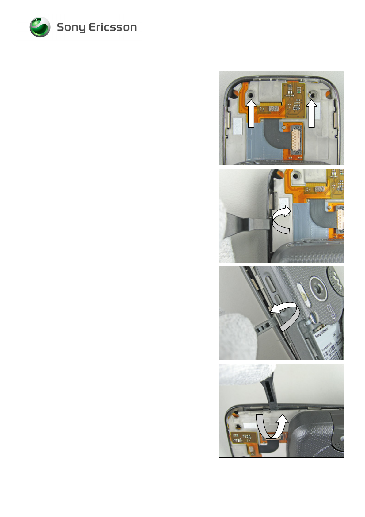
2.1.4 Dividing the Phone into Upper and Lower half’s
BE CAREFUL NOT TO DAMAGE THE FLEX FILM!
Gently bend away the flex film a little bit with a flex film
assembly tool.
Close the phone and remove the two inside screws from the
lower front assembly by using the NTZ 112 288 (torx bit no
6).
Replace the screw if it’s damaged otherwise it can be
r
Remove the two screws from the lower rear cover assembly
by using the NTZ 112 288 (torx bit no 6).
Replace the screw if it’s damaged otherwise it can be
reused.
.
Use the guitar pick to unsnap the Lower Front Cover from
the Lower Rear Cover.
Use a guitar pick and gently move it along the side until the
front is loose.
3/000 21-1/FEA 209 544/104 C
© Sony Ericsson Mobile Communications AB
11(87)
Page 12
Working Instruction, Mechanical
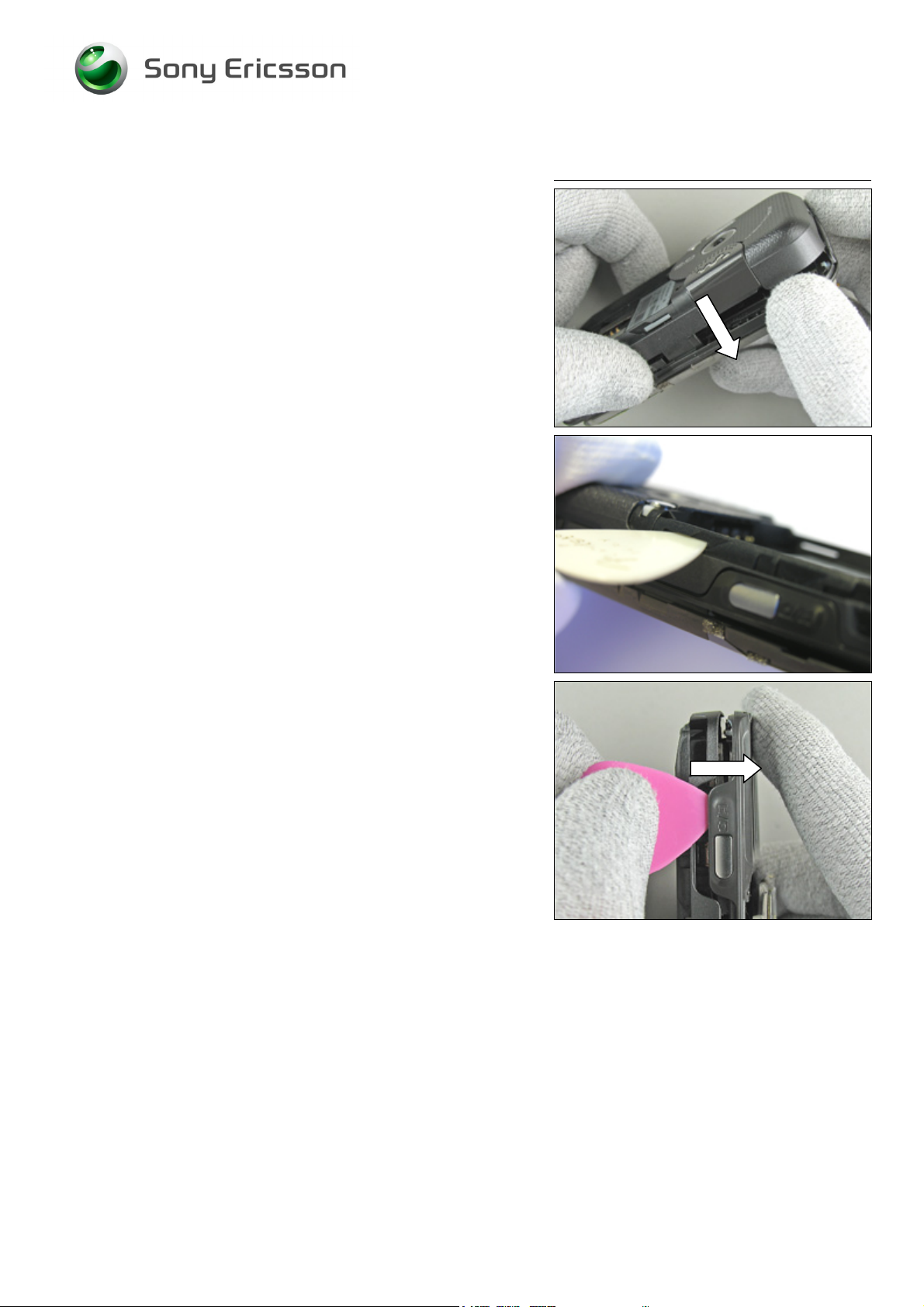
Disassembly Instruction continued
DON’T BEND THE SIDE TO MUCH DOWNWARDS!
Now should the whole side have become loose.
Repeat the same procedure on the other side.
By the camera button insert the guitar pick until you get a
gap.
3/000 21-1/FEA 209 544/104 C
© Sony Ericsson Mobile Communications AB
12(87)
Page 13
Working Instruction, Mechanical
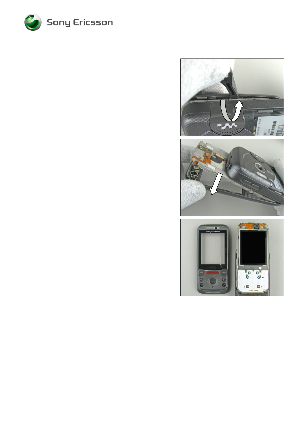
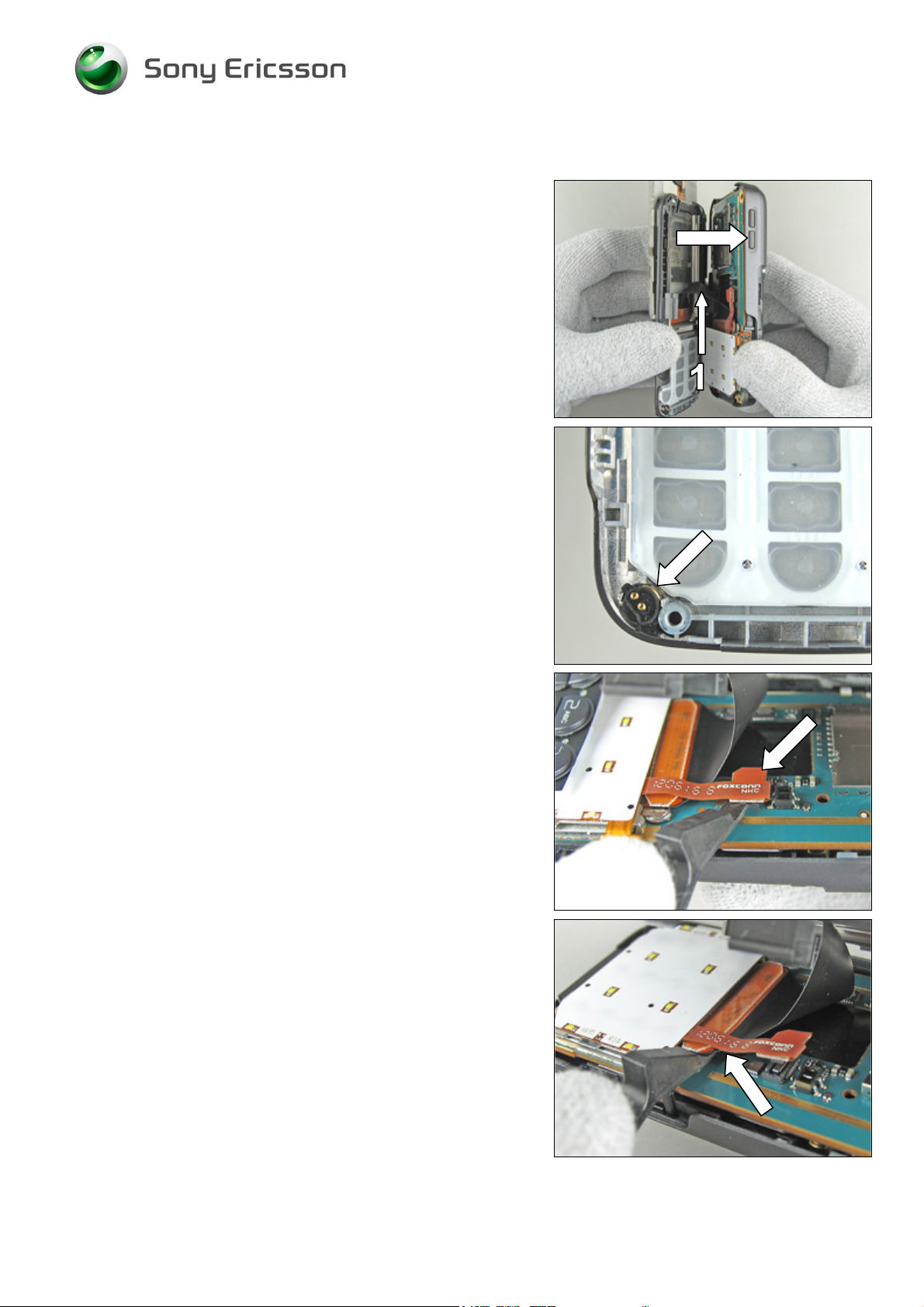
Disassembly Instruction continued
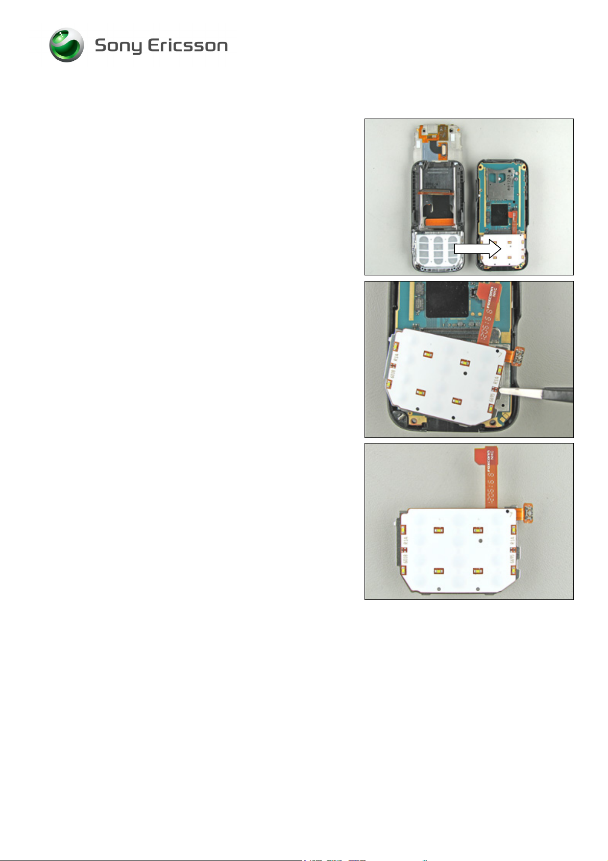
SLIDE OUT THE PHONE!
B
E CAREFUL WITH THE HALF-HALF FLEX WITH COMPONENTS
(1) WHEN THE TWO HALF’S SEPARATES FROM EACH OTHER!
Divide the phone into two half’s.
SOMETIMES THE MICROPHONE GROMMET COMES LOOSE FROM
THE LOWER FRONT ASSEMBLY
- DON’T LOOSE IT!
B
E CAREFUL WITH THE FLEX FILM AND THE B T B CONNECTOR!
Gently bend with the front opening tool under the Numeric
key foil assembly’s board to board connector like the picture
shows until the connector become loose from the main
PBA.
Do the same thing with the half-half flex with components
board to board connector.
3/000 21-1/FEA 209 544/104 C
© Sony Ericsson Mobile Communications AB
13(87)
Page 14
Working Instruction, Mechanical
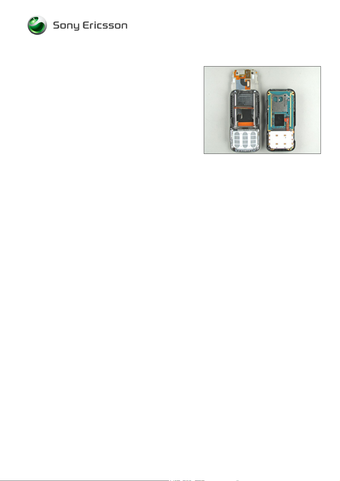
Disassembly Instruction continued
The phone is now divided into upper and lower half’s.
3/000 21-1/FEA 209 544/104 C
© Sony Ericsson Mobile Communications AB
14(87)
Page 15
Working Instruction, Mechanical
2.1.5 Numeric Key Foil assembly
O
FTEN THE NUMERIC KEY FOIL ASSEMBLY BECOMES LOOSE
WHEN THE PHONE IS DIVIDED INTO TWO HALF
’S!
Remove the numeric key foil assembly with a blunt pair of
tweezers or your fingers.
Removed numeric key foil assembly.
3/000 21-1/FEA 209 544/104 C
© Sony Ericsson Mobile Communications AB
15(87)
Page 16
Working Instruction, Mechanical
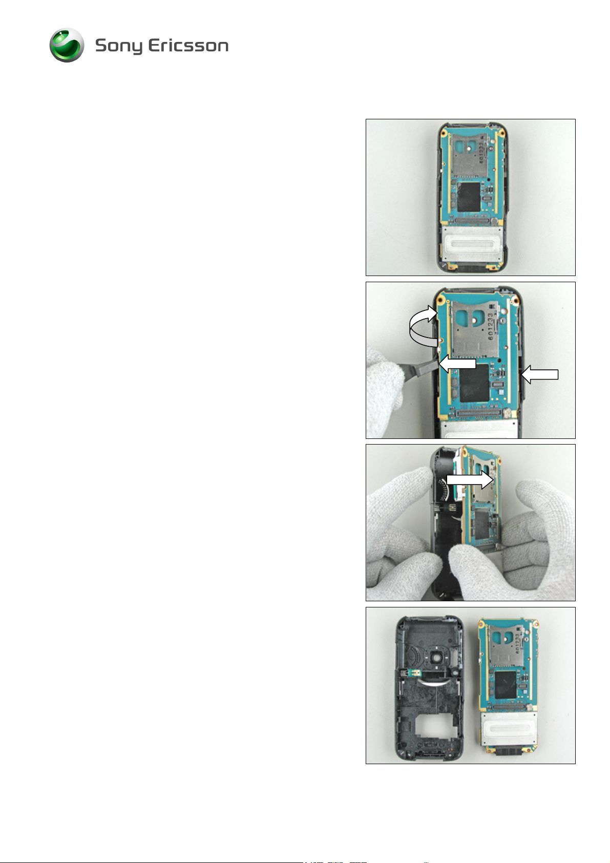
2.1.6 Lower Rear Cover Assembly (and Main PBA)
Start like this before removal of the lower rear cover
assembly.
Gently bend with the front opening tool under the main PBA
like the picture shows until the main PBA starts to become
loose on this side of the lower rear cover assembly.
If necessary do the same thing on the other side.
Start to remove the main PBA.
If necessary, wiggle the main PBA a little side to side while
pulling it away from the lower front cover assembly.
Remove the main PBA completely from the lower rear cover
assembly.
3/000 21-1/FEA 209 544/104 C
© Sony Ericsson Mobile Communications AB
16(87)
Page 17
Working Instruction, Mechanical
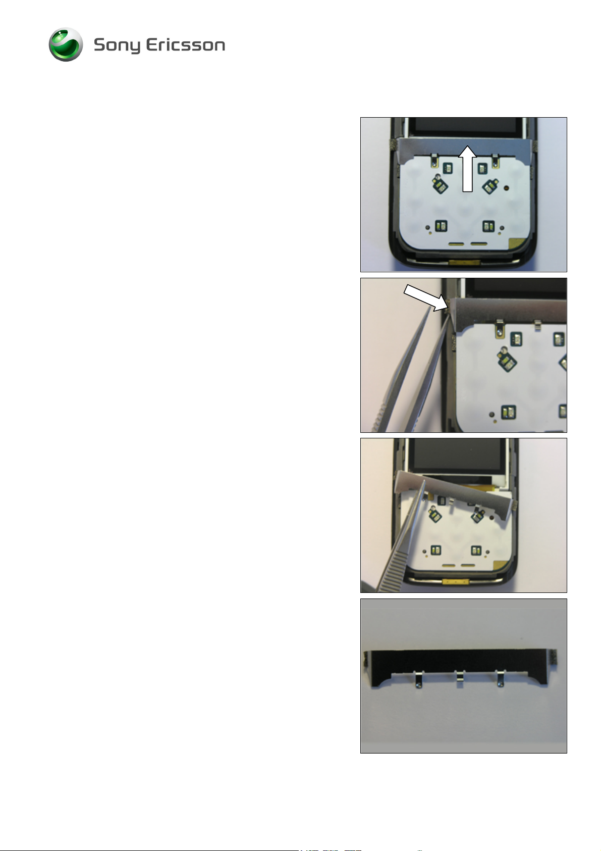
2.1.7 ESD Protection Sheet
Start like this before removal of the ESD protection sheet.
Use a blunt pair of tweezers to squeeze in between the
ESD protection sheet and the upper carrier assembly until
it’s become loose (if necessary bend a little).
Completely remove the ESD protection sheet with the
tweezers.
Removed ESD protection sheet.
3/000 21-1/FEA 209 544/104 C
© Sony Ericsson Mobile Communications AB
17(87)
Page 18
Working Instruction, Mechanical
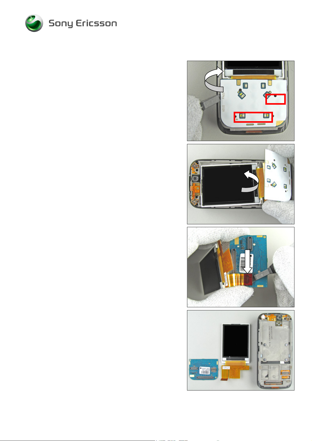
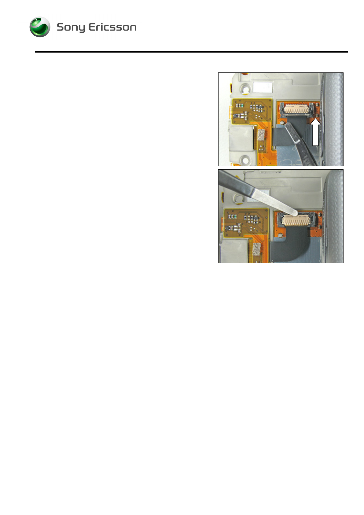
2.1.8 LCD Module and Navigation Key Foil Assembly
With the front opening tool gently bend until the navigation
key foil assembly’s two board to board connectors (marked
with red) are loose.
BE VERY CAREFUL WITH THE LCD MODULE ASSEMBLY!
Lift the LCD module together with the navigation key foil
assembly straight up
Do not ever touch the LCD glass surface.
Gently bend with the front opening tool under the LCD
module board to board connector like the picture shows
until the connector become loose from the navigation key
foil assembly.
Removed LCD module and navigation key foil assembly.
3/000 21-1/FEA 209 544/104 C
© Sony Ericsson Mobile Communications AB
18(87)
Page 19
Working Instruction, Mechanical
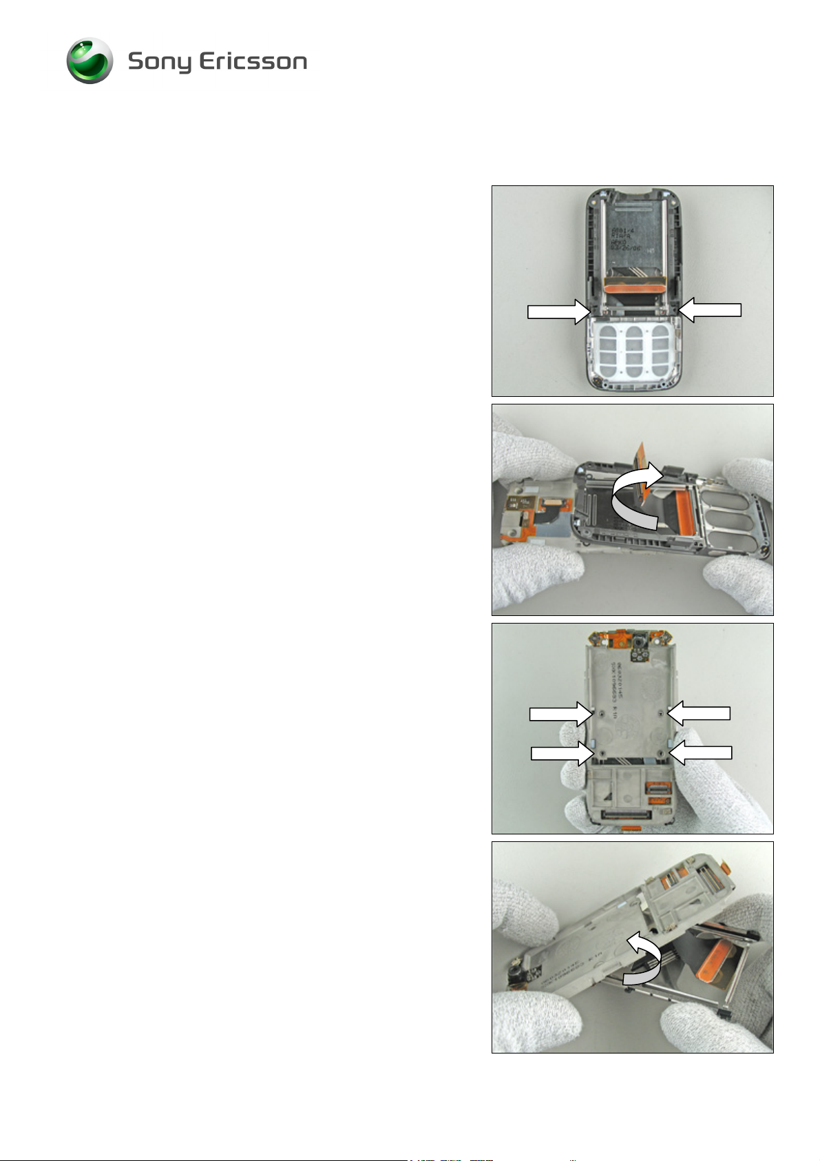
2.1.9 Lower Front Assembly, Upper Carrier Assembly and Slide
Mechanism
Remove the two screws from the lower front assembly by
using the NTZ 112 1052 (JCIS bit).
Replace the screw if it’s damaged otherwise it can be
reused.
Slide out the lower front assembly and remove it from the
upper carrier assembly.
Remove the four screws from the upper carrier assembly by
using the NTZ 112 1052 (JCIS bit).
Replace the screw with new ones.
Remove the slide mechanism from the upper carrier
assembly.
3/000 21-1/FEA 209 544/104 C
© Sony Ericsson Mobile Communications AB
19(87)
Page 20
Working Instruction, Mechanical
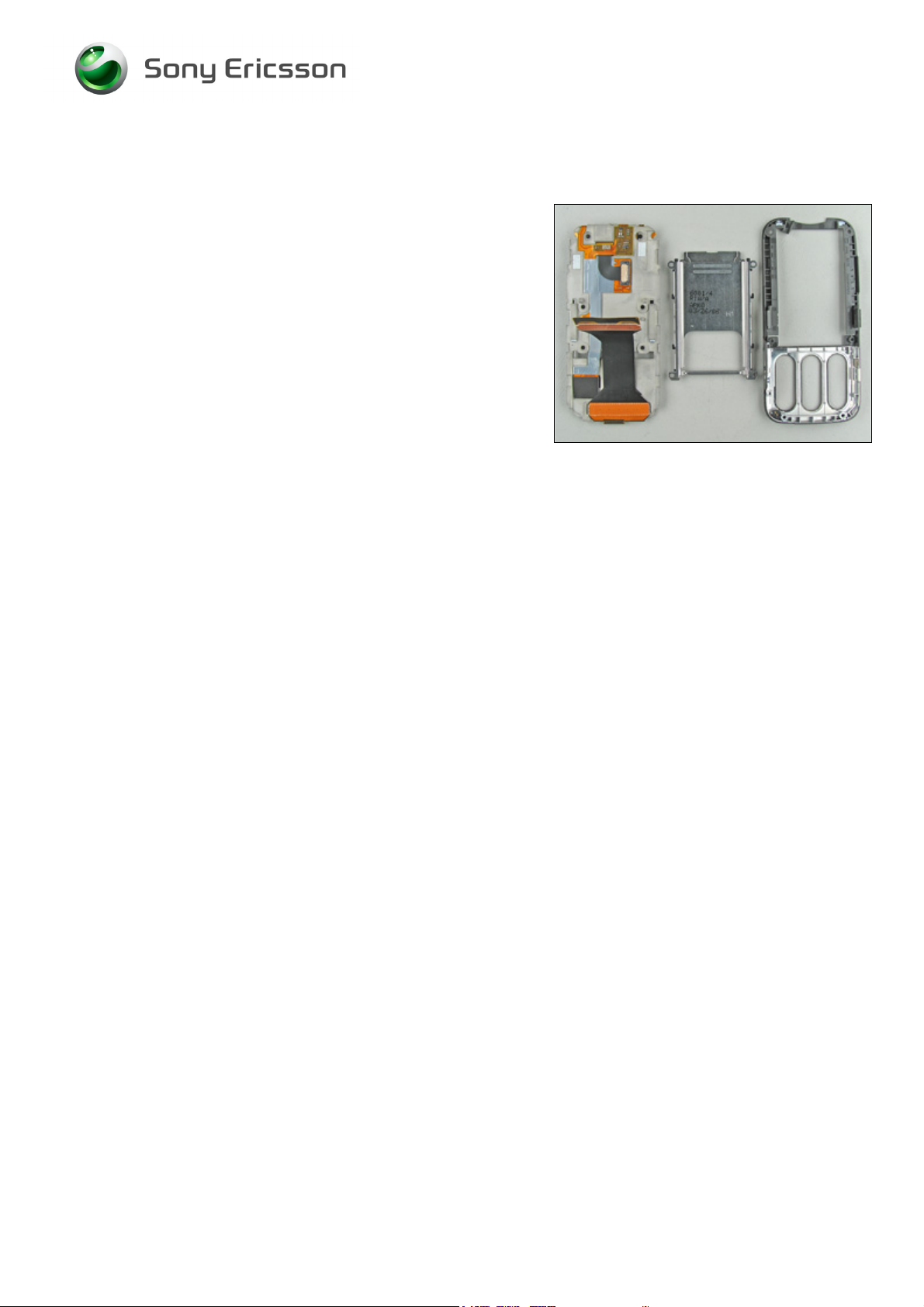
Disassembly Instruction continued
Disassembled upper carrier assembly, slide mechanism
and lower front assembly.
3/000 21-1/FEA 209 544/104 C
© Sony Ericsson Mobile Communications AB
20(87)
Page 21
Working Instruction, Mechanical
3 Replacements
Search for the part to be replaced on the Contents page and go to that instruction to be found in this
Replacements section.
The instruction usually begins by directing you to the Disassembly section with a specification of the
instructions you have to carry out in order to disassemble the phone as far as needed before the
actual replacement.
Go back to this Replacements section and carry out the instruction.
The instruction usually ends by directing you to the Reassembly section with a specification of the
instructions you have to carry out in order to reassemble the phone.
REPLACEMENTS
Start
Contents
page
DISASSEMBLY REASSEMBLY
Done
3/000 21-1/FEA 209 544/104 C
Company Internal
© Sony Ericsson Mobile Communications AB
Page 22

Working Instruction, Mechanical
3.1 Battery Cover
Follow the 2.1.1 Disassembly instructions!
Prepare the new battery cover.
Follow the 4.1.8 Reassembly instructions!
3.2 Upper Rear Lid Assembly
Follow the 2.1.1 – 2.1.2 Disassembly instructions!
Prepare the new upper rear lid assembly.
Follow the 4.1.7 – 4.1.8 Reassembly instructions!
3.3 Upper Front Assembly Complete
Follow the 2.1.1 – 2.1.3 Disassembly instructions!
Remove the keypad as described in 3.15 Keyboard Navigation.
Prepare the new Upper front assembly Complete.
Attach a new name plate as described in 3.12 Co-Brand Label.
Install the Keyboard Navigation as described in 3.15 Keyboard Navigation.
Follow the 4.1.6 – 4.1.8 Reassembly instructions!
3.4 Numeric Key Foil Assembly
Follow the 2.1.1 – 2.1.5 Disassembly instructions!
Prepare the new Numeric Key Foil Assembly.
Follow the 4.1.5 – 4.1.8 Reassembly instructions!
3.5 Lower Rear Cover assembly
Follow the 2.1.1 – 2.1.6 Disassembly instructions!
Prepare the new Lower Rear Cover Assembly.
Follow the 4.1.4 – 4.1.8 Reassembly instructions!
3.6 ESD Protection Sheet
Follow the 2.1.1 – 2.1.3, 2.1.7 Disassembly instructions!
Prepare the new ESD Protection Sheet.
Follow the 4.1.3, 4.1.6 – 4.1.8 Reassembly instructions!!
3.7 LCD Module
Follow the 2.1.1 – 2.1.3, 2.1.8 Disassembly instructions!
Prepare the new LCD Module.
Apply a new LCD tape on the LCD Module according to the 3.47 Replacement instructions!
Follow the 4.1.2, 4.1.6- 4.1.8 Reassembly instructions!
3/000 21-1/FEA 209 544/104 C
Company Internal
© Sony Ericsson Mobile Communications AB
Page 23

Working Instruction, Mechanical
3.8 Navigation Key Foil Assembly
Follow the 2.1.1 – 2.1.8 Disassembly instructions!
Prepare the new Navigation Key foil Assembly.
Follow the 4.1.2 – 4.1.8 Reassembly instructions!
3.9 Lower Front Assembly, Upper Carrier Assembly and
Slide Mechanism
Follow the 2.1.1 – 2.1.9 Disassembly instructions!
Prepare the new Lower Front Assembly, Upper Carrier Assembly and slide mechanism.
Follow the 4.1.1 – 4.1.8 Reassembly instructions!
3/000 21-1/FEA 209 544/104 C
© Sony Ericsson Mobile Communications AB
23(87)
Page 24
Working Instruction, Mechanical
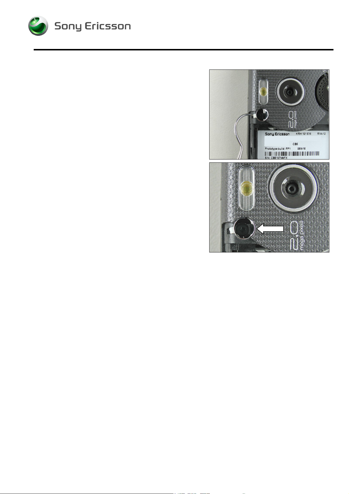
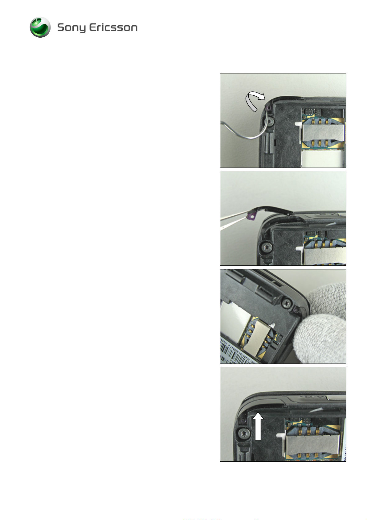
3.10 External Antenna Plug Assembly
Follow the 2.1.1 Disassembly instructions!
Remove the external antenna plug assembly with a dentist
hook.
Skip this section if you only disassemble the phone.
Can be done without any previous disassembly
Assemble a new external antenna plug assembly with your
fingers.
Follow the 4.1.8 Reassembly instructions!
3/000 21-1/FEA 209 544/104 C
Company Internal
© Sony Ericsson Mobile Communications AB
Page 25
Working Instruction, Mechanical
3.11 IRDA Window
Follow the 2.1.1 Disassembly instructions!
Start to remove the old IRDA window with a dentist hook.
Remove the IRDA window completely.
Press (quite hard) the new IRDA window into place with
your fingers.
Correctly assembled IRDA window.
Follow the 4.1.8 Reassembly instructions!
3/000 21-1/FEA 209 544/104 C
© Sony Ericsson Mobile Communications AB
25(87)
Page 26
Working Instruction, Mechanical
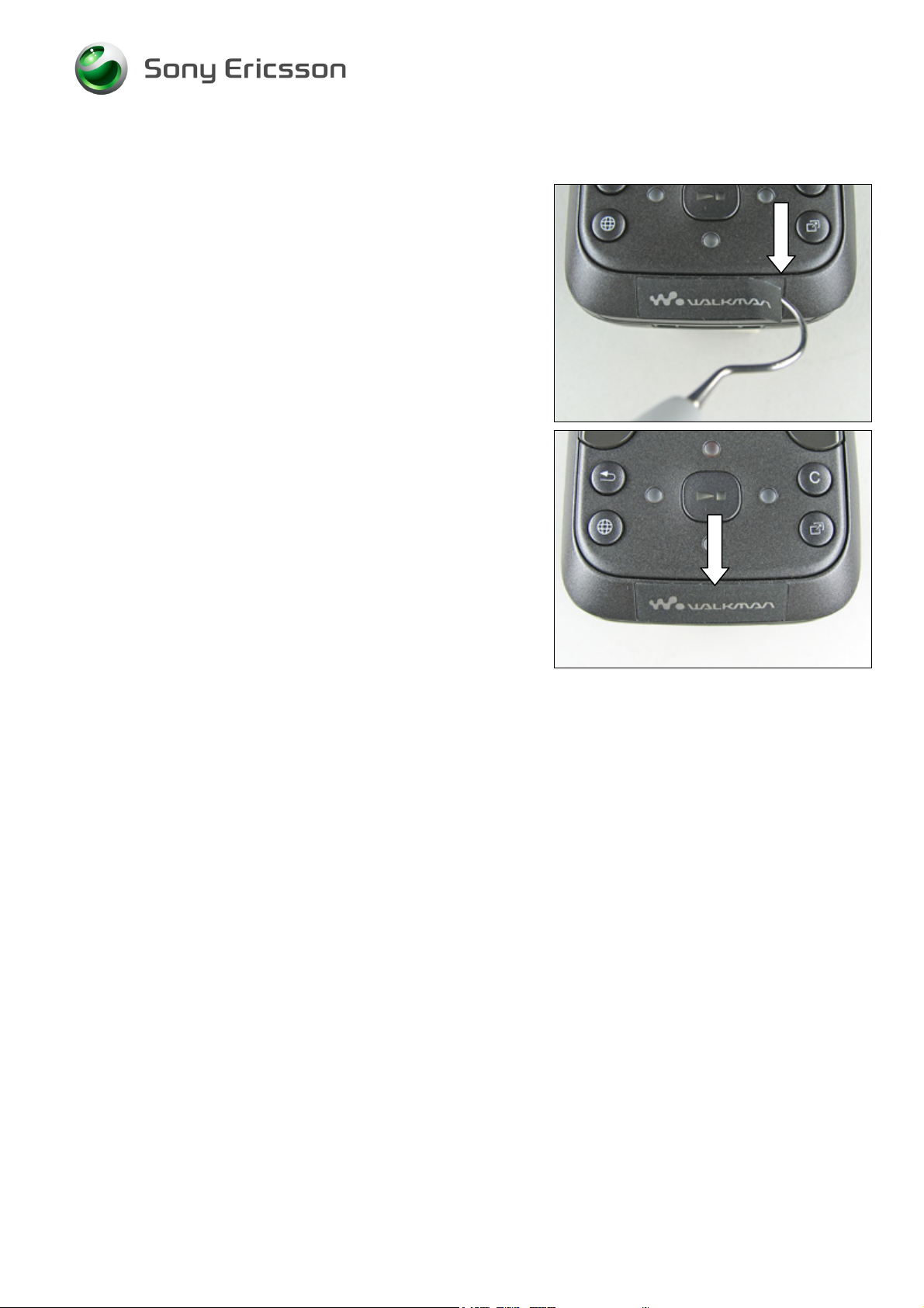
3.12 Co-Brand Label
Gently remove the old co-brand label with a dentist hook.
Skip this section if you only disassemble the phone.
Can be done without any previous disassembly!
Assemble a new co-brand label with a blunt pair of
tweezers or by hand.
Keep the pressure on for a few seconds to secure a good
fit.
3/000 21-1/FEA 209 544/104 C
© Sony Ericsson Mobile Communications AB
26(87)
Page 27
Working Instruction, Mechanical
3.13 Tape Upper Rear Lid
Follow the 2.1.1 – 2.1.2 Disassembly instructions!
Remove the old tape upper rear lid with a dentist hook.
Assemble a new (or two) tape upper rear lid with the help of
a blunt pair of tweezers.
Follow the 4.1.7 – 4.1.8 Reassembly instructions!
3/000 21-1/FEA 209 544/104 C
© Sony Ericsson Mobile Communications AB
27(87)
Page 28

Working Instruction, Mechanical
3.14 Rubber Connector, Speaker Plate
Follow the 2.1.1 – 2.1.3 Disassembly instructions!
Remove the rubber connector, speaker plate with a blunt
pair of tweezers.
Reassemble a new rubber connector, speaker plate with
the tweezers.
Follow the 4.1.6 – 4.1.8 Reassembly instructions!
3/000 21-1/FEA 209 544/104 C
© Sony Ericsson Mobile Communications AB
28(87)
Page 29

Working Instruction, Mechanical
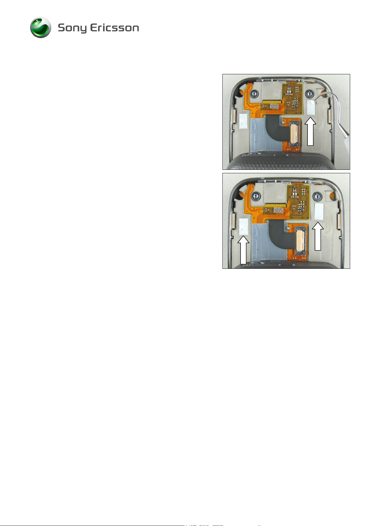
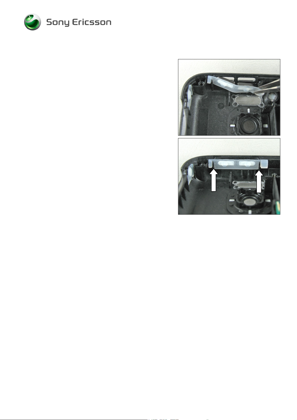
3.15 Keyboard Navigation
Follow the 2.1.1 – 2.1.3 Disassembly instructions!
Remove the old keyboard navigation with a blunt pair of
tweezers or by hand.
New keyboard navigation.
Assemble a new keyboard navigation by hand.
Make sure that the keyboard navigation is placed correctly
in the two guide cavities.
Follow the 4.1.6 – 4.1.8 Reassembly instructions!
3/000 21-1/FEA 209 544/104 C
© Sony Ericsson Mobile Communications AB
29(87)
Page 30

Working Instruction, Mechanical
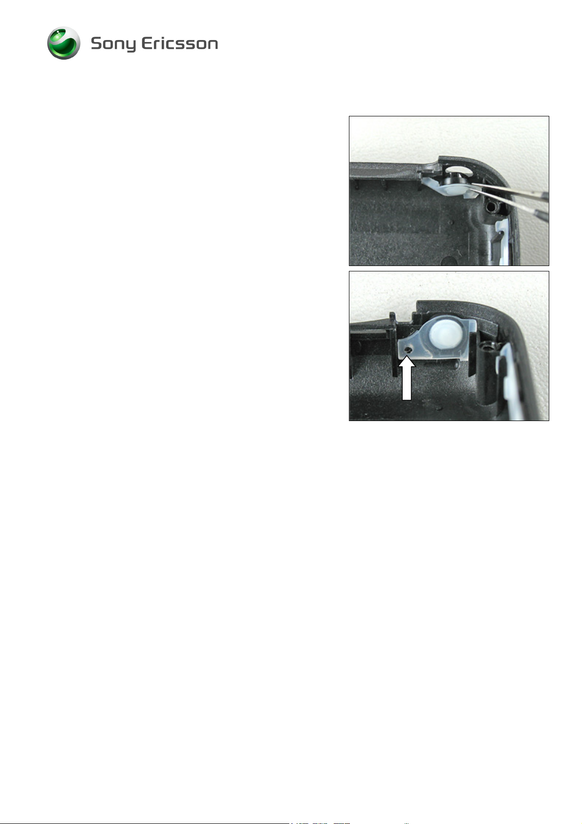
3.16 Ear Speaker
Follow the 2.1.1 – 2.1.3 Disassembly instructions!
Remove the old ear speaker with a dentist hook.
Remove the old ear speaker completely with a blunt pair of
tweezers.
WHEN ASSEMBLING A NEW EAR SPEAKER DON’T FORGET TO
REMOVE THE OLD EAR SPEAKER GASKET IN THE UPPER FRONT
ASSEMBLY COMPLETE
.
Use a blunt pair of tweezers or a dentist hook for removal of
the old gasket.
O NOT TOUCH OR BEND THE CONTACT SPRINGS!
D
Assemble a new ear speaker into the cavity and press
gently with the tweezers and hold it there for a few seconds
to secure a god fit.
3/000 21-1/FEA 209 544/104 C
© Sony Ericsson Mobile Communications AB
30(87)
Page 31

Working Instruction, Mechanical
Make sure that the new ear speaker is correctly assembled.
Check so there is no damage on the connection springs.
Follow the 4.1.6 – 4.1.8 Reassembly instructions!
3/000 21-1/FEA 209 544/104 C
© Sony Ericsson Mobile Communications AB
31(87)
Page 32

Working Instruction, Mechanical
3.17 Water Indicator
Follow the 2.1.1 – 2.1.6 Disassembly instructions!
Remove the old water indicator with a dentist hook.
Assemble a new water indicator with a blunt pair of
tweezers.
Follow the 4.1.4 – 4.1.8 Reassembly instructions!
INSPECTION (FROM THE OUTSIDE)
Check for water damage on the water indicator.
With the battery cover assembly and the battery removed!
3/000 21-1/FEA 209 544/104 C
© Sony Ericsson Mobile Communications AB
32(87)
Page 33

Working Instruction, Mechanical
3.18 Duo Lid
Follow the 2.1.1 – 2.1.4 Disassembly instructions!
Remove the old duo lid and replace it with a new one.
Use a blunt pair of tweezers during the assembly.
Correctly assembled duo lid.
Follow the 4.1.5 – 4.1.8 Reassembly instructions!
3/000 21-1/FEA 209 544/104 C
© Sony Ericsson Mobile Communications AB
33(87)
Page 34

Working Instruction, Mechanical
3.19 Keyboard Numeric
Follow the 2.1.1 – 2.1.4 Disassembly instructions!
Remove the old keyboard numeric.
c
Assemble a new keyboard numeric with your fingers.
Make sure it’s assembled in the correct position – notice the
guide pins in the lower front assembly.
Follow the 4.1.5 – 4.1.8 Reassembly instructions!
3/000 21-1/FEA 209 544/104 C
© Sony Ericsson Mobile Communications AB
34(87)
Page 35

Working Instruction, Mechanical
3.20 Microphone Grommet
Follow the 2.1.1 – 2.1.4 Disassembly instructions!
Remove the old microphone grommet with a blunt pair of
tweezers.
Assemble a new microphone grommet into the lower front
assembly with the tweezers.
Make sure that the microphone grommet is assembled in
the right position.
Follow the 4.1.5 – 4.1.8 Reassembly instructions!
3/000 21-1/FEA 209 544/104 C
© Sony Ericsson Mobile Communications AB
35(87)
Page 36

Working Instruction, Mechanical
3.21 Microphone
Follow the 2.1.1 – 2.1.4 Disassembly instructions!
Remove the old microphone with a blunt pair of tweezers.
Assemble a new microphone into the lower front assembly
with the tweezers.
Make sure that the microphone is assembled in the right
position.
Follow the 4.1.5 – 4.1.8 Reassembly instructions!
3/000 21-1/FEA 209 544/104 C
© Sony Ericsson Mobile Communications AB
36(87)
Page 37

Working Instruction, Mechanical
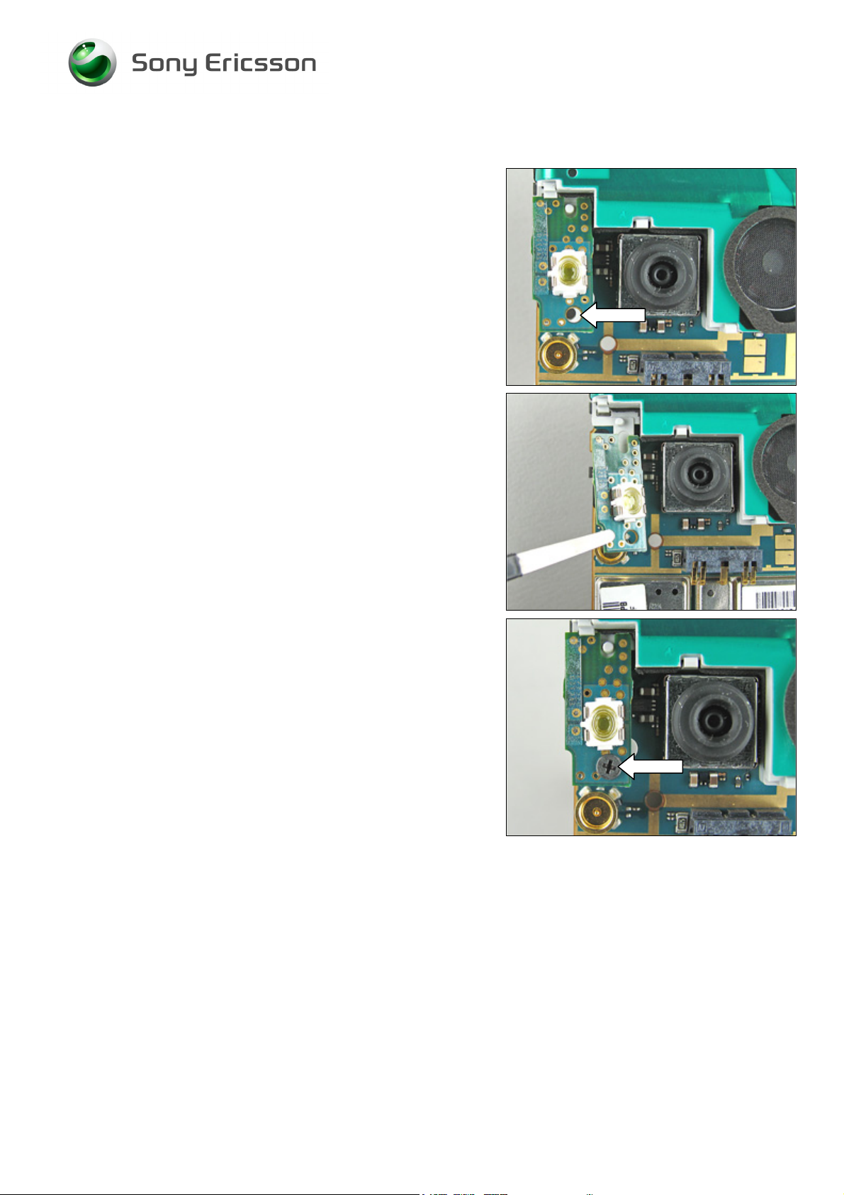
3.22 Camera Key
Follow the 2.1.1 – 2.1.4 Disassembly instructions!
Remove the old camera key with a blunt pair of tweezers.
Assemble a new camera key into the lower front assembly
with the tweezers.
Make sure that the camera key is assembled in the right
position (use the guide pins).
Follow the 4.1.5 – 4.1.8 Reassembly instructions!
3/000 21-1/FEA 209 544/104 C
© Sony Ericsson Mobile Communications AB
37(87)
Page 38
Working Instruction, Mechanical
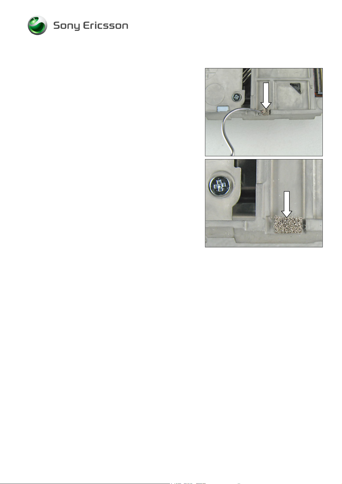
3.23 Conductive Gasket
NOTICE! THERE ARE SEVERAL CONDUCTIVE GASKETS INSIDE
THE PHONE
Remove the old conductive gasket with a dentist hook/ blunt
pair of tweezers.
.
Assemble a new (or more) conductive gasket with the help
of a blunt pair of tweezers.
3/000 21-1/FEA 209 544/104 C
© Sony Ericsson Mobile Communications AB
38(87)
Page 39

Working Instruction, Mechanical
3.24 Tape for Slider Mechanism
Follow the 2.1.1 – 2.1.9 Disassembly instructions!
Remove the old tape for slider mechanism with a dentist
hook.
Assembly a new tape for slider mechanism with a blunt pair
of tweezers.
Follow the 4.1.1 Reassembly instructions!
3/000 21-1/FEA 209 544/104 C
© Sony Ericsson Mobile Communications AB
39(87)
Page 40

Working Instruction, Mechanical
3.25 Damper for Lower Front (1)
Follow the 2.1.1 – 2.1.4 Disassembly instructions!
This is the damper that shall be removed.
Start to remove the old damper for lower front (1) by
pushing it out from the back with a blunt pair of tweezers.
Assemble a new damper for lower front (1) with the
tweezers – push it into the correct position.
Follow the 4.1.5 – 4.1.8 Reassembly instructions!
3/000 21-1/FEA 209 544/104 C
© Sony Ericsson Mobile Communications AB
40(87)
Page 41

Working Instruction, Mechanical
3.26 Damper for Lower Front (2)
Follow the 2.1.1 – 2.1.4 Disassembly instructions!
Start to remove the old damper for lower front (2) with a
dentist hook.
Remove the old damper with a blunt pair of tweezers
Assemble a new damper for lower front (2) with the
tweezers – push it into the correct position.
Follow the 4.1.5 – 4.1.8 Reassembly instructions!
3/000 21-1/FEA 209 544/104 C
© Sony Ericsson Mobile Communications AB
41(87)
Page 42

Working Instruction, Mechanical
3.27 VGA Camera Gasket
Follow the 2.1.1 – 2.1.3 Disassembly instructions!
Remove the old VGA camera gasket with a dentist hook.
Assemble a new VGA camera gasket with the help of a
blunt pair of tweezers.
Follow the 4.1.6 – 4.1.8 Reassembly instructions!
3/000 21-1/FEA 209 544/104 C
© Sony Ericsson Mobile Communications AB
42(87)
Page 43

Working Instruction, Mechanical
3.28 Camera Module (VGA) With Flex
Follow the 2.1.1 – 2.1.3 Disassembly instructions!
Open the FPC connector with a blunt pair of tweezers.
Disconnect the camera module (VGA) flex film with the flex
film assembly tool.
Remove the camera module (VGA).
Gently lift the LCD Module assembly just enough to slide
out the camera module (VGA).
Slide in a new camera module (VGA) into the correct
position on the upper carrier assembly.
3/000 21-1/FEA 209 544/104 C
© Sony Ericsson Mobile Communications AB
43(87)
Page 44
Working Instruction, Mechanical
Replacement Instruction continued
Reconnect the camera module (VGA) flex film with the flex
film assembly tool.
Close the FPC connector with a blunt pair of tweezers.
Follow the 4.1.6 – 4.1.8 Reassembly instructions!
3/000 21-1/FEA 209 544/104 C
Company Internal
© Sony Ericsson Mobile Communications AB
Page 45

Working Instruction, Mechanical
3.29 Half- Half Flex with Components
Follow the 2.1.1 – 2.1.9 Disassembly instructions!
Gently bend with a flex film assembly tool under the halfhalf flex with components board to board connector like the
picture shows until the half-half flex with components
become loose from the upper carrier assembly.
IF YOU HAVE EXCHANGED THE MAIN FLEX ASSEMBLY BEFORE,
MAKE SURE THAT IS PLACED IN THE MIDDLE OF THE SLOT IN
THE UPPER CARRIER ASSEMBLY
OTHERWISE THE HALF-HALF FLEX WITH COMPONENTS WILL
NOT FIT INTO THE SLOT!
.
Assemble a new half-half flex with components.
Use your fingers to keep the pressure on for a few seconds
to secure a good fit.
A new half-half flex with components mounted on an upper
carrier assembly.
Follow the 4.1.1 – 4.1.8 Reassembly instructions!
3/000 21-1/FEA 209 544/104 C
© Sony Ericsson Mobile Communications AB
45(87)
Page 46

Working Instruction, Mechanical
3.30 Adhesive Half to Half
Follow the 2.1.1 – 2.1.9 Disassembly instructions!
Remove the old adhesive half to half with a dentist hook or
a blunt pair of tweezers.
Assemble a new adhesive half to half with the help of a
blunt pair of tweezers.
Follow the 4.1.1 – 4.1.8 Reassembly instructions!
3/000 21-1/FEA 209 544/104 C
© Sony Ericsson Mobile Communications AB
46(87)
Page 47

Working Instruction, Mechanical
3.31 Main Flex Assembly
Follow the 2.1.1 – 2.1.9 Disassembly instructions!
Gently bend with a blunt pair of tweezers under the main
flex assembly like the picture shows until it becomes loose
from the upper carrier assembly.
Do the same thing as above but now on the other side.
Fold away the flex film but this time use the flex film
assembly tool.
BE VERY CAREFUL WITH THE MAIN FLEX ASSEMBLY!
Continue to use the flex film assembly tool until the whole
main flex assembly is totally free from the upper carrier
assembly.
3/000 21-1/FEA 209 544/104 C
© Sony Ericsson Mobile Communications AB
47(87)
Page 48

Working Instruction, Mechanical
Replacement Instruction continued
Remove the main flex assembly with the flex film assembly
tool.
Start to reassemble a new main flex assembly.
Make sure that the main flex assembly is assembled in the
right position (use the guide pin).
Gently fold the flex film into the correct position.
Check that all of the flaps on the main flex assembly are
correctly assembled (use the guide pins by the arrows).
Follow the 4.1.1 – 4.1.8 Reassembly instructions!
3/000 21-1/FEA 209 544/104 C
Company Internal
© Sony Ericsson Mobile Communications AB
Page 49

Working Instruction, Mechanical
3.32 Lower Damper for Upper Carrier Assembly
Follow the 2.1.1 – 2.1.9 Disassembly instructions!
Start to remove the old lower damper for upper carrier
assembly by pushing them out from the back with a blunt
pair of tweezers.
Completely remove the old dampers with the tweezers.
Assemble new dampers with the tweezers or your fingers.
Follow the 4.1.1 – 4.1.8 Reassembly instructions!
3/000 21-1/FEA 209 544/104 C
© Sony Ericsson Mobile Communications AB
49(87)
Page 50

Working Instruction, Mechanical
3.33 Protective Tape, Test Points
Follow the 2.1.1 – 2.1.4 Disassembly instructions!
Remove the old protective tape, test points with a dentist
hook.
Assemble a new protective tape, test points with the help of
a blunt pair of tweezers.
Follow the 4.1.5 – 4.1.8 Reassembly instructions!
3/000 21-1/FEA 209 544/104 C
© Sony Ericsson Mobile Communications AB
50(87)
Page 51

Working Instruction, Mechanical
3.34 Vibrator
Follow the 2.1.1 – 2.1.6 Disassembly instructions!
O NOT TOUCH THE VIBRATOR CONTACT SPRINGS OR DAMAGE
D
THE FLYWHEEL
Start to lift up the vibrator with a blunt pair of tweezers.
!
Remove the old vibrator with a blunt pair of tweezers.
Press the vibrator to the bottom of the cavity gently with a
blunt pair of tweezers (don’t press on the contact springs).
Check the new contact springs that they are in good
condition and that they are not bent.
Follow the 4.1.4 – 4.1.8 Reassembly instructions!
3/000 21-1/FEA 209 544/104 C
Company Internal
© Sony Ericsson Mobile Communications AB
Page 52
Working Instruction, Mechanical
3.35 Volume Keys
Follow the 2.1.1 – 2.1.6 Disassembly instructions!
Remove the old volume keys with a blunt pair of tweezers.
Assemble a new volume key into the lower rear cover
assembly with the tweezers. Make sure that the volume key
is assembled in the right position.
Follow the 4.1.4 – 4.1.8 Reassembly instructions!
3/000 21-1/FEA 209 544/104 C
© Sony Ericsson Mobile Communications AB
52(87)
Page 53
Working Instruction, Mechanical
3.36 On/Off Key
Follow the 2.1.1 – 2.1.6 Disassembly instructions!
Remove the old on/off key with a blunt pair of tweezers.
Assemble a new on/off key into the lower rear cover
assembly with the tweezers. Make sure that the on/off key
is assembled in the right position.
Follow the 4.1.4 – 4.1.8 Reassembly instructions!
3/000 21-1/FEA 209 544/104 C
© Sony Ericsson Mobile Communications AB
53(87)
Page 54

Working Instruction, Mechanical
3.37 BT Antenna
Follow the 2.1.1 – 2.1.6 Disassembly instructions!
Insert the dentist hook from underneath and bend until the
BT antenna becomes totally free.
Remove the old BT antenna with a blunt pair of tweezers.
Assemble a new BT antenna with the tweezers.
Make sure that the BT antenna is assembled in the right
position.
Follow the 4.1.4 – 4.1.8 Reassembly instructions!
3/000 21-1/FEA 209 544/104 C
© Sony Ericsson Mobile Communications AB
54(87)
Page 55

Working Instruction, Mechanical
3.38 System Connector
Follow the 2.1.1 – 2.1.6 Disassembly instructions!
Remove the old system connector by hand.
Skip this section if you only disassemble the phone.
Assemble a new system connector with your fingers.
Press the system connector firmly to the bottom of the main
PBA.
Picture shows a correct assembled system connector.
Follow the 4.1.4 – 4.1.8 Reassembly instructions!
3/000 21-1/FEA 209 544/104 C
Company Internal
© Sony Ericsson Mobile Communications AB
Page 56

Working Instruction, Mechanical
3.39 Dust Gasket, System Connector
Follow the 2.1.1 – 2.1.6 Disassembly instructions!
Remove the old dust gasket by hand.
Assemble a new dust gasket with your fingers.
Press the dust gasket firmly to the bottom of the main PBA.
Picture shows a correct assembled dust gasket.
Follow the 4.1.4 – 4.1.8 Reassembly instructions!
3/000 21-1/FEA 209 544/104 C
© Sony Ericsson Mobile Communications AB
56(87)
Page 57

Working Instruction, Mechanical
3.40 Insulation Label
Follow the 2.1.1 – 2.1.6 Disassembly instructions!
Remove the old insulation label with a dentist hook.
Assemble a new insulation label with the help of a blunt pair
of tweezers.
Follow the 4.1.4 – 4.1.8 Reassembly instructions!
3/000 21-1/FEA 209 544/104 C
© Sony Ericsson Mobile Communications AB
57(87)
Page 58

Working Instruction, Mechanical
3.41 Flash Reflector
Follow the 2.1.1 – 2.1.6 Disassembly instructions!
Remove the old flash reflector with your fingers.
Pull straight up.
Assemble a new flash reflector with your fingers.
Follow the 4.1.4 – 4.1.8 Reassembly instructions!
3/000 21-1/FEA 209 544/104 C
© Sony Ericsson Mobile Communications AB
58(87)
Page 59
Working Instruction, Mechanical
3.42 LED-Flash Assembly
Follow the 2.1.1 – 2.1.6 Disassembly instructions!
Remove the inside screw from the loud speaker box
assembly by using the NTZ 112 1052 (JCIS bit).
Replace the screw if it’s damaged otherwise it can be
reused.
Remove the LED-flash assembly with a blunt pair of
tweezers.
APPLY 7 NCM
NTZ 112
1052 (JCIS BIT)!
±
1.5 NCM OF TORQUE FOR THE SCREW USING
Assemble and tighten the screw in the new LED-flash
assembly.
The LED-flash assembly is now reassembled.
Replace the screws if it’s damaged otherwise it can be
reused.
Follow the 4.1.4 – 4.1.8 Reassembly instructions!
3/000 21-1/FEA 209 544/104 C
© Sony Ericsson Mobile Communications AB
59(87)
Page 60

Working Instruction, Mechanical
3.43 Loud Speaker Box Assembly
Follow the 2.1.1 – 2.1.6 Disassembly instructions!
Start like this before removal of the loud speaker box
assembly.
Remove the inside screw from the main PBA by using the
NTZ 112 288 (torx bit no 6).
Replace the screw if it’s damaged otherwise it can be
reused.
Remove the whole loud speaker box assembly by hand.
3/000 21-1/FEA 209 544/104 C
© Sony Ericsson Mobile Communications AB
60(87)
Page 61

Working Instruction, Mechanical
Replacement Instruction continued
Begin by placing the new loud speaker box assembly
against the main PBA.
Make sure that the loud speaker box assembly is mounted
correctly.
APPLY 15 NCM
NTZ 112
288 (TORX BIT NO 6)!
±
1.5 NCM OF TORQUE FOR THE SCREW USING
Assemble and tighten the screw in the main PBA.
The loud speaker box assembly is now reassembled.
Replace the screws if it’s damaged otherwise it can be
reused.
Follow the 4.1.4 – 4.1.8 Reassembly instructions!
3/000 21-1/FEA 209 544/104 C
Company Internal
© Sony Ericsson Mobile Communications AB
Page 62

Working Instruction, Mechanical
3.44 Camera Rubber
Follow the 2.1.1 – 2.1.6 Disassembly instructions!
Remove the old camera rubber with a blunt pair of
tweezers.
Assemble a new camera rubber with your fingers.
Follow the 4.1.4 – 4.1.8 Reassembly instructions!
3/000 21-1/FEA 209 544/104 C
© Sony Ericsson Mobile Communications AB
62(87)
Page 63

Working Instruction, Mechanical
3.45 Shield Can Camera Module
Follow the 2.1.1 – 2.1.6 Disassembly instructions!
Gently release the shield can camera module with a dentist
hook, work your way around the shield until it becomes
completely loose.
Remove the camera shield with your fingers.
Reassemble a new shield can camera module with your
fingers.
Follow the 4.1.4 – 4.1.8 Reassembly instructions!
3/000 21-1/FEA 209 544/104 C
© Sony Ericsson Mobile Communications AB
63(87)
Page 64

Working Instruction, Mechanical
3.46 Camera Module 2M FF
Follow the 2.1.1 – 2.1.6 Disassembly instructions!
EVER TOUCH THE CAMERA LENS!
N
Start by pressing the mega camera removal tool over the
camera module 2M FF all the way to the bottom.
If necessary wiggle the camera tool a little side to side and
at the same time pull the camera module 2M FF straight up
(together with the tool) from the socket.
Remove (with your fingers) the old camera module 2M FF
from the camera tool.
Notice the small slot in the Notice the small slot in the
camera module 2M FF socket.
3/000 21-1/FEA 209 544/104 C
© Sony Ericsson Mobile Communications AB
64(87)
Page 65

Working Instruction, Mechanical
Replacement Instruction continued
Press gently on the top of the camera module 2M FF until it
snaps into place.
Make sure that the camera module 2M FF is in the right
position (to the bottom of the socket and properly locked).
Follow the 4.1.4 – 4.1.8 Reassembly instructions!
3/000 21-1/FEA 209 544/104 C
Company Internal
© Sony Ericsson Mobile Communications AB
Page 66

Working Instruction, Mechanical
3.47 LCD Tape
Follow the 2.1.1 – 2.1.3, 2.1.8 Disassembly instructions!
Remove the old LCD tape with a dentist hook.
Assemble a new LCD tape with the help of a blunt pair of
tweezers.
Follow the 4.1.2, 4.1.6- 4.1.8 Reassembly instructions!
3/000 21-1/FEA 209 544/104 C
© Sony Ericsson Mobile Communications AB
66(87)
Page 67

Working Instruction, Mechanical
3.48 Slide Mechanism Protection Tape
Follow the 2.1.1 – 2.1.6 Disassembly instructions!
Remove the old slide mechanism protection tape with a
dentist hook.
Assemble a new slide mechanism protection tape with the
help of a blunt pair of tweezers.
Follow the 4.1.4 – 4.1.8 Reassembly instructions!
3/000 21-1/FEA 209 544/104 C
© Sony Ericsson Mobile Communications AB
67(87)
Page 68
Working Instruction, Mechanical
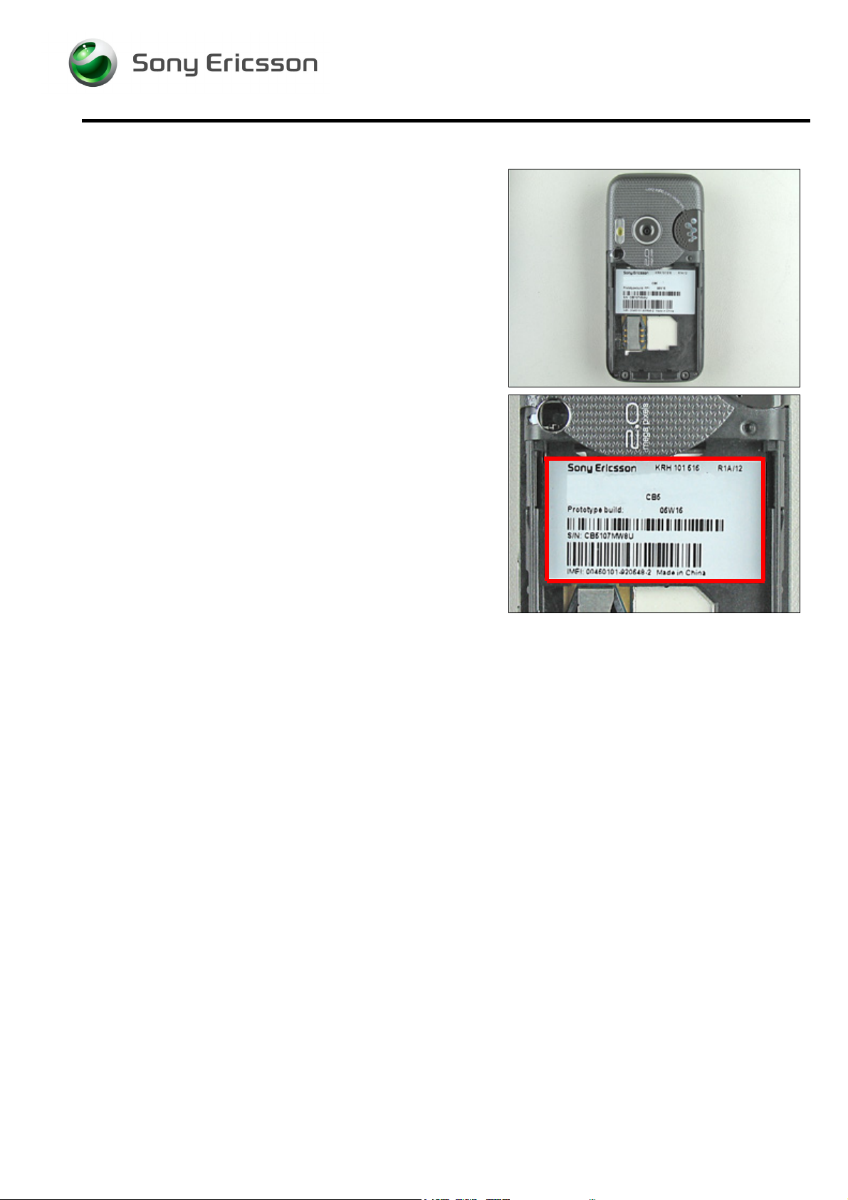
3.49 Label
Follow the 2.1.1Disassembly instructions!
Read the old label and/or write the information into the
“Label make” program before removal
Note the position of the label before removal
Heat up the label by using hot air, if needed.
Carefully remove the label without causing scratches
If there still are residues, clean the surface with isopropyl
alcohol
Check that the proper label format is loaded in the Zebra
printer.
Write a new label by using the program “Label make” and
check that the printing is OK.
Take the new label and place it onto the frame as in the
adjacent picture.
O
NE LABEL ONLY IS ALLOWED!
Follow the 4.1.8 Reassembly instructions!
3/000 21-1/FEA 209 544/104 C
Company Internal
© Sony Ericsson Mobile Communications AB
Page 69

Working Instruction, Mechanical
4 Reassembly
After replacing a part being listed in Replacements, the instruction of that section usually ends by
directing you to this Reassembly section with a specification of the instructions you have to carry out
in order to reassemble the phone.
REPLACEMENTS
Start
Contents
page
DISASSEMBLY
4.1 Overview
The reassembly is done in the following sequence:
1. Upper Carrier Assembly (a), Slide Mechanism (b) and
Lower Front Assembly (c)
2. LCD Module Assembly
3. ESD Protection Sheet
4. Main PBA
5. Lower Rear Cover Assembly
6. Numeric Key Foil Assembly
7. Upper Front Assembly Complete
8. Upper Rear Lid
9. Battery (a) and Battery Cover (b)
REASSEMBLY
Done
3/000 21-1/FEA 209 544/104 C
© Sony Ericsson Mobile Communications AB
69(87)
Page 70

Working Instruction, Mechanical
4.1.1 Upper Carrier Assembly, Slide Mechanism and Lower
Front Assembly
Start like this before reassembling of the upper carrier
assembly, slide mechanism and lower front assembly.
If you are going to assembly a new slide mechanism
remove these four tapes from the upper carrier assembly.
Start to assemble the slide mechanism in the lower front
assembly.
Hold the slide mechanism like this before installation of the
two screws.
3/000 21-1/FEA 209 544/104 C
Company Internal
© Sony Ericsson Mobile Communications AB
Page 71

Working Instruction, Mechanical
APPLY 10 NCM
NTZ 112
1052 (JCIS BIT)!
±
1.5 NCM OF TORQUE FOR THE SCREW USING
Assemble and tighten the two screws in the lower front
assembly.
Replace the screws if it’s damaged otherwise it can be
reused.
3/000 21-1/FEA 209 544/104 C
© Sony Ericsson Mobile Communications AB
71(87)
Page 72

Working Instruction, Mechanical
Reassembly Instruction continued
Take the upper carrier assembly and slide in the half –half
flex into the lower front assembly.
Put it in the correct position like the picture shows.
APPLY 15 NCM
NTZ 112
1052 (JCIS BIT)!
±
1.5 NCM OF TORQUE FOR THE SCREW USING
Assemble and tighten four screws in the upper carrier
assembly.
Replace the screws with new ones.
Slide the two half’s together.
3/000 21-1/FEA 209 544/104 C
Company Internal
© Sony Ericsson Mobile Communications AB
Page 73

Working Instruction, Mechanical
4.1.2 LCD Module Assembly and Navigation Key Foil Assembly
Start like this before reassembling of the new LCD module
assembly.
Connect the LCD module’s board to board connector to the
navigation key foil assembly, use your fingers.
Now the LCD module assembly is ready for the next step.
Slide in the LCD module assembly against the upper carrier
assembly.
Gently fold the LCD module assembly towards the upper
carrier assembly until the LCD module assembly is in the
correct position.
3/000 21-1/FEA 209 544/104 C
© Sony Ericsson Mobile Communications AB
73(87)
Page 74

Working Instruction, Mechanical
Reassembly Instruction continued
LCD module assembly correct assembled into the phone.
Gently fold the navigation key foil assembly over the upper
carrier assembly.
Notice the two board to board connector’s position!
BE CAREFUL WITH THE LCD MODULE ASSEMBLY WHEN
ROTATING THE PHONE BACK AND FORTH
!
Press together the two board to board connectors with your
fingers.
1. Start with the small one.
2. Continue then with the large one.
Don’t apply pressure on the two b t b connectors until you
are certain that you have a “match”.
Make sure that the two board to board connectors are
closed.
3/000 21-1/FEA 209 544/104 C
Company Internal
© Sony Ericsson Mobile Communications AB
Page 75

Working Instruction, Mechanical
4.1.3 ESD Protection Sheet
Start to reassemble the ESD protection sheet.
Snap/click the ESD protection sheet into the correct position
with your fingers.
3/000 21-1/FEA 209 544/104 C
© Sony Ericsson Mobile Communications AB
75(87)
Page 76

Working Instruction, Mechanical
4.1.4 Lower Rear Cover Assembly (and Main PBA)
BE VERY CAREFUL WITH THE ON/OFF KEY (1), VOLUME KEY (2),
WHEN THE MAIN PBA IS ASSEMBLED IN THE LOWER REAR
COVER ASSEMBLY
KEY BUTTONS!
Start like this before reassembling of the main PBA in the
lower rear cover assembly.
- IT’S EASY TO SQUEEZE OR DAMAGE THE
Place the main PBA assembly towards the front end of the
lower rear cover assembly.
Sometimes the rubber keys are in the way when folding the
main PBA into place in the lower rear cover assembly.
Gently push the rubber keys into place (if necessary) by
using a pair of tweezers or a dentist hook (See caution text
above).
Gently fold the main PBA into the lower rear cover
assembly.
Gently snap down the main PBA into the lower rear cover
assembly (use your fingers).
Check so the main PBA is correctly assembled in the lower
rear cover assembly.
3/000 21-1/FEA 209 544/104 C
Company Internal
© Sony Ericsson Mobile Communications AB
Page 77

Working Instruction, Mechanical
4.1.5 Reassembly of the Phones Upper and Lower half’s
Together with the Numeric Key Foil Assembly
SLIDE OUT THE PHONE!
E CAREFUL WITH THE FLEX FILM!
B
Hold the two half’s of the phone like the picture shows and
connect the half-half flex with components board to board
connector to the main PBA with your fingers.
Put in the numeric key foil assembly into the lower half of
the phone.
Slide in the camera button flex film into the correct position
in lower rear cover assembly.
Connect the numeric key foil assembly’s board to board
connector to the main PBA with your fingers.
3/000 21-1/FEA 209 544/104 C
© Sony Ericsson Mobile Communications AB
77(87)
Page 78

Working Instruction, Mechanical
Reassembly Instruction continued
Take the duo lid and put it into the correct position on the
lower front assembly– use a blunt pair of tweezers or your
fingers.
Make sure that the microphone grommet (1) and the
keyboard numeric (2) are correctly assembled.
Gently close the two half’s of the phone together.
Turn the phone around.
AKE SURE THAT THE KEYBOARD NUMERIC IS IN THE CORRECT
M
POSITION BEFORE YOU START TO SQUEEZE THE TWO HALF
TOGETHER
!
’S
3/000 21-1/FEA 209 544/104 C
Company Internal
© Sony Ericsson Mobile Communications AB
Page 79

Working Instruction, Mechanical
Reassembly Instruction continued
Continue to snap the phone together inn the middle.
MAKE SURE THAT THE DUO LID IS ASSEMBLED IN THE CORRECT
POSITION
!
And finally, snap together the top of the phone.
PPLY 15 NCM ± 1.5 NCM OF TORQUE FOR THE SCREWS USING
A
NTZ 112
288 (TORX BIT NO 6)!
Assemble and tighten the two screws in the lower rear
cover assembly.
Replace the screw if it’s damaged otherwise it can be
reused.
Slide the phone together.
3/000 21-1/FEA 209 544/104 C
© Sony Ericsson Mobile Communications AB
79(87)
Page 80

Working Instruction, Mechanical
APPLY 15 NCM
NTZ 112
G
ASSEMBLY TOOL
288 (TORX BIT NO 6)!
ENTLY BEND UP THE TWO FLEX FILMS WITH THE FLEX FILM
±
1.5 NCM OF TORQUE FOR THE SCREWS USING
!
Assemble and tighten the two screws in the lower rear
cover assembly.
Replace the screw if it’s damaged otherwise it can be
reused.
BE CAREFUL WITH THE FLEX FILMS!
Gently fold back the two flex films with the flex film
assembly tool towards the upper carrier assembly guide
pins.
3/000 21-1/FEA 209 544/104 C
© Sony Ericsson Mobile Communications AB
80(87)
Page 81
Working Instruction, Mechanical
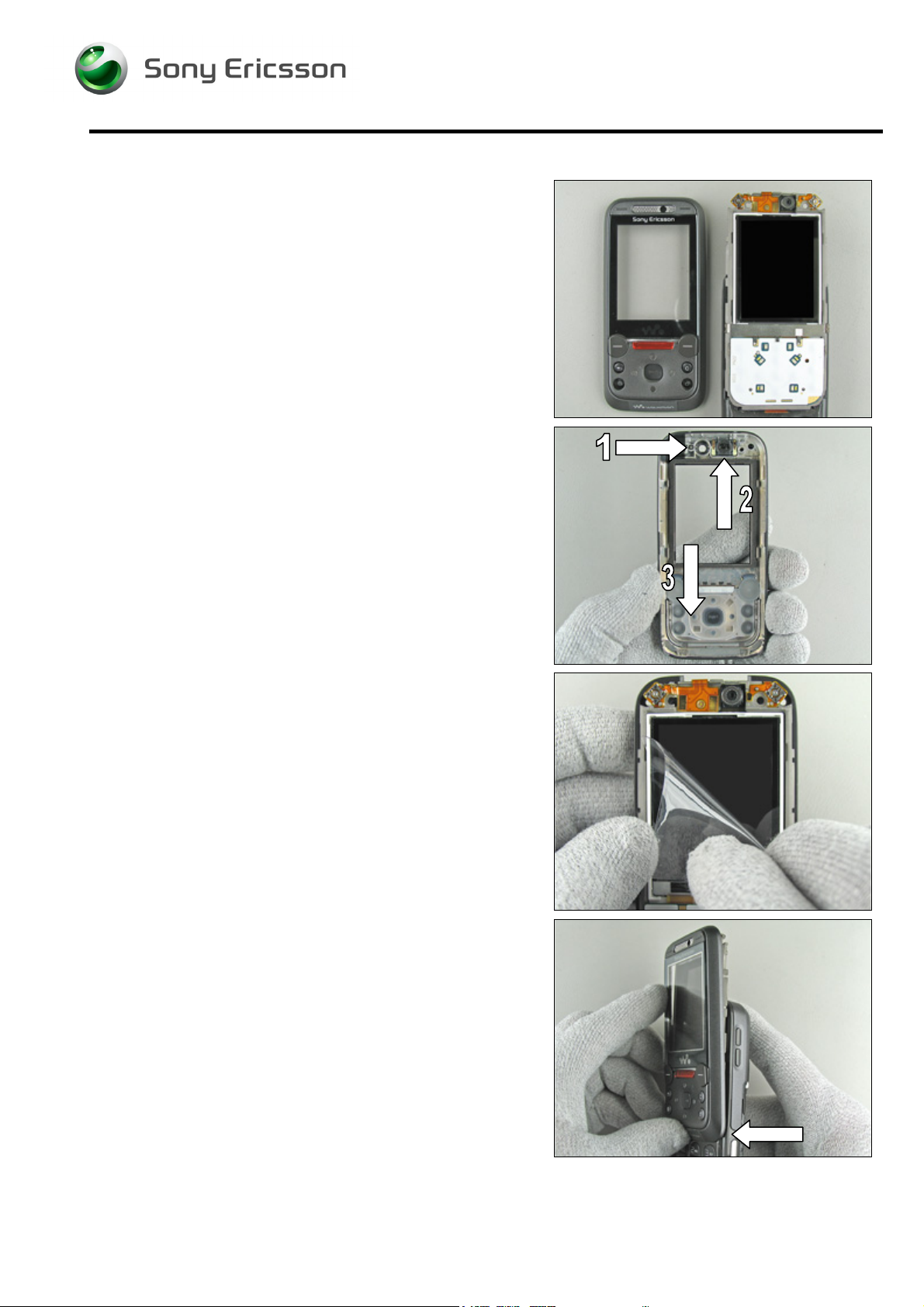
4.1.6 Upper Front Assembly Complete
Slide out the phone.
Start like this before reassembling of the upper front
assembly complete.
MAKE SURE EVERYTHING INSIDE THE UPPER FRONT COVER
COMPLETE IS ASSEMBLED
1. Rubber connector, speaker plate
2. Ear speaker
3. Keyboard navigation
!
D
ON’T FORGET TO REMOVE THE PROTECTIVE TAPE FROM THE
NEW LCD MODULE BEFORE REASSEMBLING THE UPPER FRONT
ASSEMBLY COMPLETE
!
Do not touch the LCD glass surface. Blow away dust with
an ionized air gun or blower.
Start to reassemble the upper front assembly complete.
Begin from the bottom of the phone then gently continue to
squeeze the upper front assembly complete towards the top
of the phone.
3/000 21-1/FEA 209 544/104 C
Company Internal
© Sony Ericsson Mobile Communications AB
Page 82

Working Instruction, Mechanical
Reassembly Instruction continued
Make sure that the two snap fit hooks in the upper front
assembly complete are locked against the upper carrier
assembly.
APPLY 15 NCM
NTZ 112
288 (TORX BIT NO 6)!
±
1.5 NCM OF TORQUE FOR THE SCREWS USING
Assemble and tighten the two screws in the upper carrier
assembly.
Replace the screw if it’s damaged otherwise it can be
reused.
3/000 21-1/FEA 209 544/104 C
© Sony Ericsson Mobile Communications AB
82(87)
Page 83

Working Instruction, Mechanical
4.1.7 Upper Rear Lid Assembly
Start to assemble the upper rear lid assembly.
Slide in the upper rear lid assembly completely.
“Lock” the upper rear lid assembly by pressing it down until
you hear a click sound.
Do the same thing on the other side.
3/000 21-1/FEA 209 544/104 C
© Sony Ericsson Mobile Communications AB
83(87)
Page 84

Working Instruction, Mechanical
Reassembly Instruction continued
Upper rear lid assembly reassembled.
3/000 21-1/FEA 209 544/104 C
Company Internal
© Sony Ericsson Mobile Communications AB
Page 85

Working Instruction, Mechanical
4.1.8 Battery and Battery Cover
Start like this before reassembling of the battery and the
battery cover.
Lay down the top of the battery into the frame cavity.
Start to slide on the battery cover.
With your fingers, push on the battery cover until it is
completely closed.
3/000 21-1/FEA 209 544/104 C
© Sony Ericsson Mobile Communications AB
85(87)
Page 86

Working Instruction, Mechanical
Reassembly Instruction continued
The phone is now totally reassembled.
3/000 21-1/FEA 209 544/104 C
Company Internal
© Sony Ericsson Mobile Communications AB
Page 87

Working Instruction, Mechanical
5 Revision history
Rev. Date Changes / Comments
A 2006-09-20 Initial release
B 2006-09-25 Added LCD tape and changed part LCD Module assembly to
LCD Module part number RNH 942 271
C 2006-10-05 Removal of tapes
3/000 21-1/FEA 209 544/104 C
Company Internal
© Sony Ericsson Mobile Communications AB
 Loading...