

Page 1
Trouble Shooting Guide, Mechanical
Trouble Shooting Guide, Mechanical
Applicable for W850
Contents
General ...............................................................................................................2
1
1.1 Service functions in the software...........................................................2
1.2 Misuse and other no warranty issues ....................................................3
2 Appearance Problems....................................................................................... 6
3 Network/Signal Problems .................................................................................8
4 On/Off Problems ..............................................................................................11
5 Audio Problems ...............................................................................................13
6 Key Problems................................................................................................... 18
7 Slider Problems ...............................................................................................24
8 Display Problems ............................................................................................25
9 Illumination Problems .....................................................................................29
10 Alert Problems ................................................................................................. 30
11 SIM Problems...................................................................................................31
12 Charging/Capacity Problems .........................................................................32
13 Camera Problems ............................................................................................ 34
14 Data Communication Problems .....................................................................40
15 Software Problems ..........................................................................................41
16 Revision History ..............................................................................................42
4/000 21-1/FEA 209 544/104 A
Company Internal
© Sony Ericsson Mobile Communications AB
Page 2

Trouble Shooting Guide, Mechanical
1 General
This document outlines the mechanical repairs that should be made in an attempt to fix the common failures that are seen in the
field. To gain a complete understanding of how to test and repair a specific failure, this document should be used in conjunction
with the Test Instructions, Mechanical and the Working Instructions, Mechanical.
1.1 Service functions in the software
The service menu will be accessed with the following key combination. Use the navigation keys ⇒*⇐⇐*⇐*
They are as follows:
Service info
Service settings
Service tests
Text labels
The phones software has a built in service functionality that allows you to test some of the phones functions. (See point 2 above) It
looks like this:
Main display
LED/illumination
Keyboard
Speaker
Earphone
Microphone
Vibrator
Camera
Flash LED
Video call camera
Memory Stick
FM Radio
Real time clock
Total call time
NOTE: Different names will occur depending on language setting and customization.
4/000 21-1/FEA 209 544/104 A
Company Internal
© Sony Ericsson Mobile Communications AB
2(42)
Page 3

Trouble Shooting Guide, Mechanical
1.2 Misuse and other no warranty issues
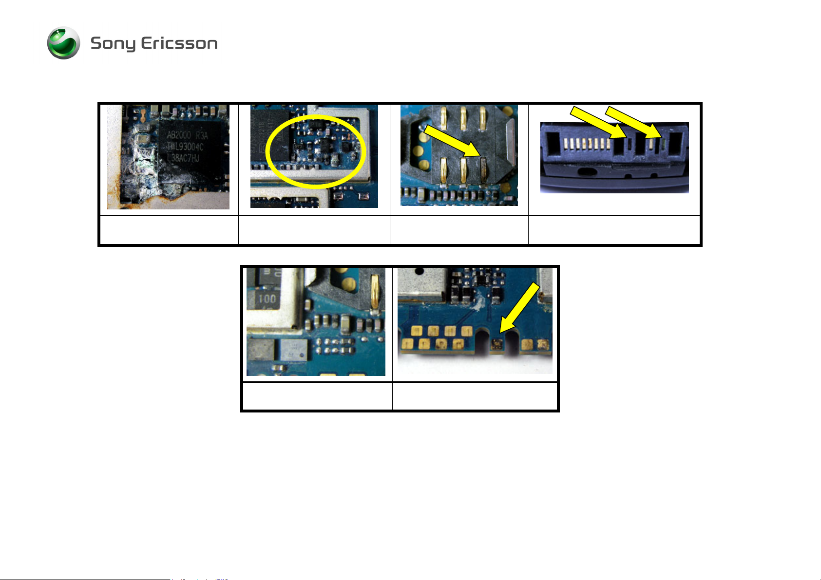
Misuse is not covered by warranty. This chapter will explain what’s not covered by warranty. Phones that have been exposed to
misuse will not be covered by warranty.
This means: if it is possible to repair the phone, the customer will have to pay for the repair. SEMC will not allow any of these
phones to be claimed into WCMS. Some local perspectives may interfere with this. Please reference to local directives.
1.2.1 Action
Make a general visual inspection for misuse.
Below are some examples of what is not covered by warranty.
Front window broken
due to misuse.
4/000 21-1/FEA 209 544/104 A
Company Internal
© Sony Ericsson Mobile Communications AB
LCD cracked due to
drop.
Clear scratches Mark after drop Corrosion components
on the PCB.
3(42)
Page 4
Trouble Shooting Guide, Mechanical
Corrosion components on
Corrosion components on the
the PCB.
Components around system
connector damaged by liquid
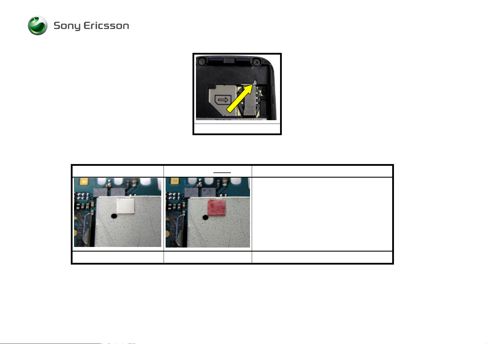
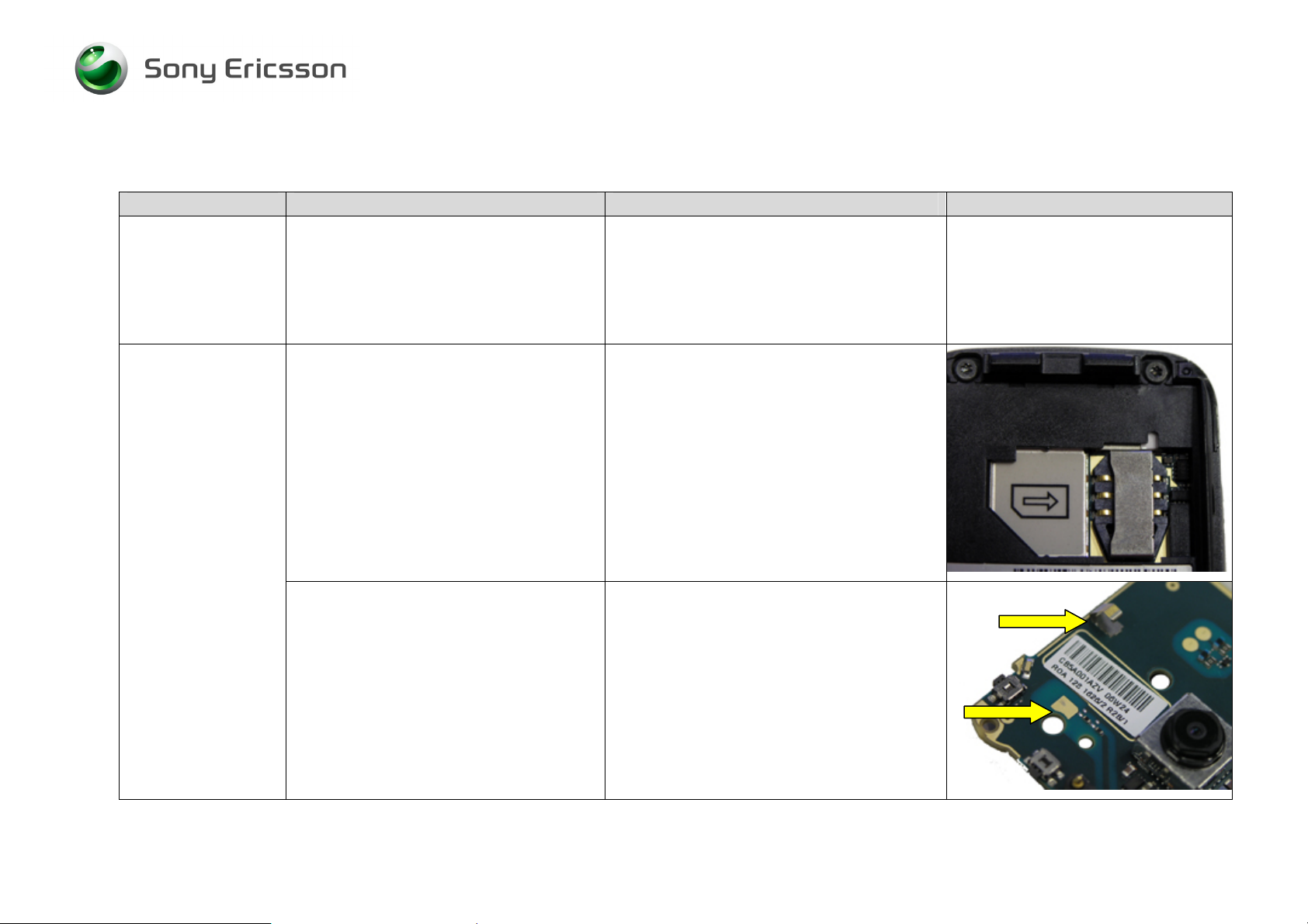
1.2.2 Liquid damage sticker
In the phone there is placed a sticker that can give you a hint to see if the phone is damage by liquid or not. This sticker is located
near the SIM reader (Fig. 1.2.1) and it is possible to see it without disassemble the phone.
PCB.
SIM reader damaged by
liquid.
System connector pad(s)
damaged by liquid
System connector damaged by
liquid
4/000 21-1/FEA 209 544/104 A
Company Internal
© Sony Ericsson Mobile Communications AB
4(42)
Page 5
Trouble Shooting Guide, Mechanical
Fig. 1.2.1
On the pictures below you will see the different between a sticker that has been in contact with liquid (Fig. 1.2.3) and with one that
hasn’t (Fig. 1.2.2).
This sticker is ok This sticker is not
1.2.3 Action
Make a general visual inspection for misuse, corrosion or oxidation from liquid damage. No further action should be taken for a liquid
damaged phone. Handle the unit according to local directives.
4/000 21-1/FEA 209 544/104 A
Company Internal
© Sony Ericsson Mobile Communications AB
ok
Fig. 1.2.2 Fig. 1.2.3
The white sticker that has been in contact with
liquid turns into a red or pink sticker. In this
case you should check the phone for liquid
damage
(See point 1.1.1)
.
Note: There must be clear marks after liquid on
the PCB before rejecting the phone for repair.
5(42)
Page 6
Trouble Shooting Guide, Mechanical
2 Appearance Problems
Problem Area Items to Check Repair Action Reference Image
Appearance
Visually inspect the cosmetic quality of
all user viewable surfaces
• If dirty – Clean parts as necessary.
• If unacceptably scratched or damaged
– Replace damage parts as necessary.
NOTE: Misuse is not covered by
warranty. Refer to chapter 1.2
Visually inspect all keys
Visually inspect for improper gap
between seams
• If dirty – Clean parts as necessary.
• If unacceptably scratched or damaged
– Replace damaged parts as
necessary.
NOTE: Misuse is not covered by
warranty. Refer to chapter 1.2
• Reassemble or replace damaged parts
as necessary.
4/000 21-1/FEA 209 544/104 A
Company Internal
© Sony Ericsson Mobile Communications AB
6(42)
Page 7

Trouble Shooting Guide, Mechanical
Problem Area Items to Check Repair Action Reference Image
4/000 21-1/FEA 209 544/104 A
Company Internal
© Sony Ericsson Mobile Communications AB
7(42)
Page 8
Trouble Shooting Guide, Mechanical
3 Network/Signal Problems
Problem Area Items to Check Repair Action Reference Image
Before proceeding !
• Do software update content refresh.
Note: this problem will not be solved be
a regular software update.
Note: Software Update Content Refresh
will erase all user data.
No Signal or Poor
Signal
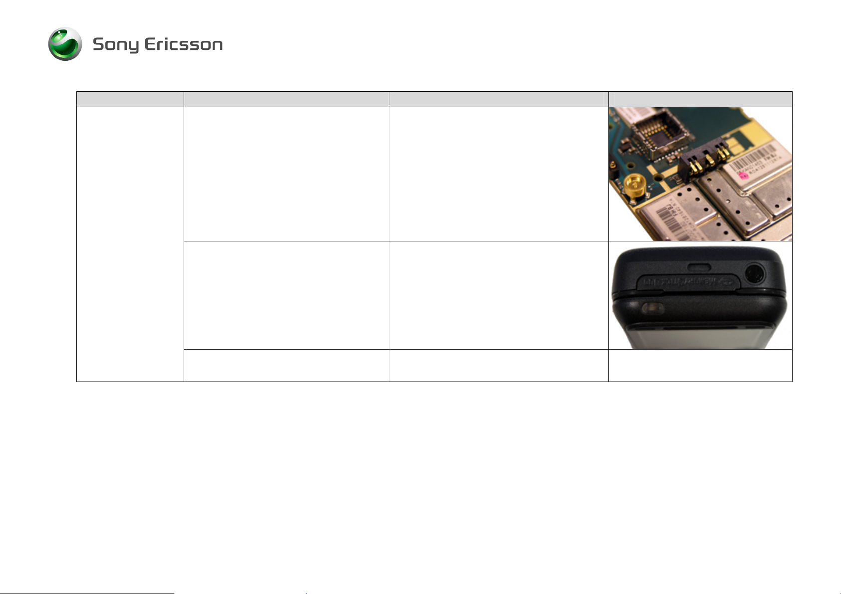
Visually inspect SIM holder
Visually inspect antenna contact pads
and the antenna connector.
• If dirty or oxidized – Clean it
• If damaged – Send to electrical repair.
• If dirty or oxidized – Clean the pads
and replace the antenna assembly.
Note: Do not bend the antenna
connector.
4/000 21-1/FEA 209 544/104 A
Company Internal
© Sony Ericsson Mobile Communications AB
8(42)
Page 9
Trouble Shooting Guide, Mechanical
Problem Area Items to Check Repair Action Reference Image
Visually inspect antenna
• If dirty, oxidized or damaged – Replace
it.
4/000 21-1/FEA 209 544/104 A
Company Internal
© Sony Ericsson Mobile Communications AB
If the issue has not been resolved !
• Handle the unit according to local
directives.
9(42)
Page 10

Trouble Shooting Guide, Mechanical
Problem Area Items to Check Repair Action Reference Image
No signal when
using external
antenna (ex. Hands
free in car).
Connect the phone to a handsfree car
kit connected with external antenna.
Visually inspect the antenna bar on the
phone.
If the issue has not been resolved !
• If no or only very less signal – Push
the middle pin of the ext. antenna
connector a few times
Note: Take care not to scratch the gold
surface.
• Handle the unit according to local
directives.
4/000 21-1/FEA 209 544/104 A
Company Internal
© Sony Ericsson Mobile Communications AB
10(42)
Page 11

Trouble Shooting Guide, Mechanical
4 On/Off Problems
Problem Area Items to Check Repair Action Reference Image
Power On
problems
Check whether the phone vibrates 10 to
15 seconds after pressing the power
key and whether the keypad illuminates
• If activation of the vibrator or keypad
are detected, refer to the “Display
Problems” chapter 7
Before proceeding !
Cannot be power on,
Cannot be detected on USB cable on
EMMA III.
Visually inspect contact pads on battery
• Do software update content refresh.
Note: this problem will not be solved be
a regular software update.
Note: Software Update Content Refresh
will erase all user data.
1. Log on to EMMA as usual.
2. Use SEPI A1 with power charger
attached.
3. Press keys 2 and 5 when you connect
the phone.
• If dirty or oxidized – Clean pads.
• If damaged – Replace the battery.
4/000 21-1/FEA 209 544/104 A
Company Internal
© Sony Ericsson Mobile Communications AB
11(42)
Page 12
Trouble Shooting Guide, Mechanical
Problem Area Items to Check Repair Action Reference Image
Visually inspect battery connector
Visually inspect the power key
• If dirty or oxidized – Clean it.
Note: Take care not to bend the
connector pin’s
• If damaged – Send to an electrical
repair location.
• If damaged – Replace on/off key.
4/000 21-1/FEA 209 544/104 A
Company Internal
© Sony Ericsson Mobile Communications AB
If the issue has not been resolved !
• Handle the unit according to local
directives.
12(42)
Page 13

Trouble Shooting Guide, Mechanical
5 Audio Problems
Problem Area Items to Check Repair Action Reference Image
Microphone:
Before proceeding !
• Do software update content refresh.
Note: this problem will not be solved be
a regular software update.
Note: Software Update Content Refresh
will erase all user data.
Visually inspect the microphone’s
external port
If the issue has not been resolved !
If the issue has not been resolved !
• If clogged – Clean.
Note: It can easily happen that the
customer blocks the microphone port
with there hand. If no fault found.
Please inform the customer where the
port is and that it is important not to
cover it during calls
• Replace microphone and microphone
grommet.
• Handle the unit according to local
directives.
4/000 21-1/FEA 209 544/104 A
Company Internal
© Sony Ericsson Mobile Communications AB
13(42)
Page 14

Trouble Shooting Guide, Mechanical
Problem Area Items to Check Repair Action Reference Image
Receiver
(earphone):
No sound or poor
quality sound
Before proceeding !
• Do software update content refresh.
Note: this problem will not be solved be
a regular software update.
Note: Software Update Content Refresh
will erase all user data.
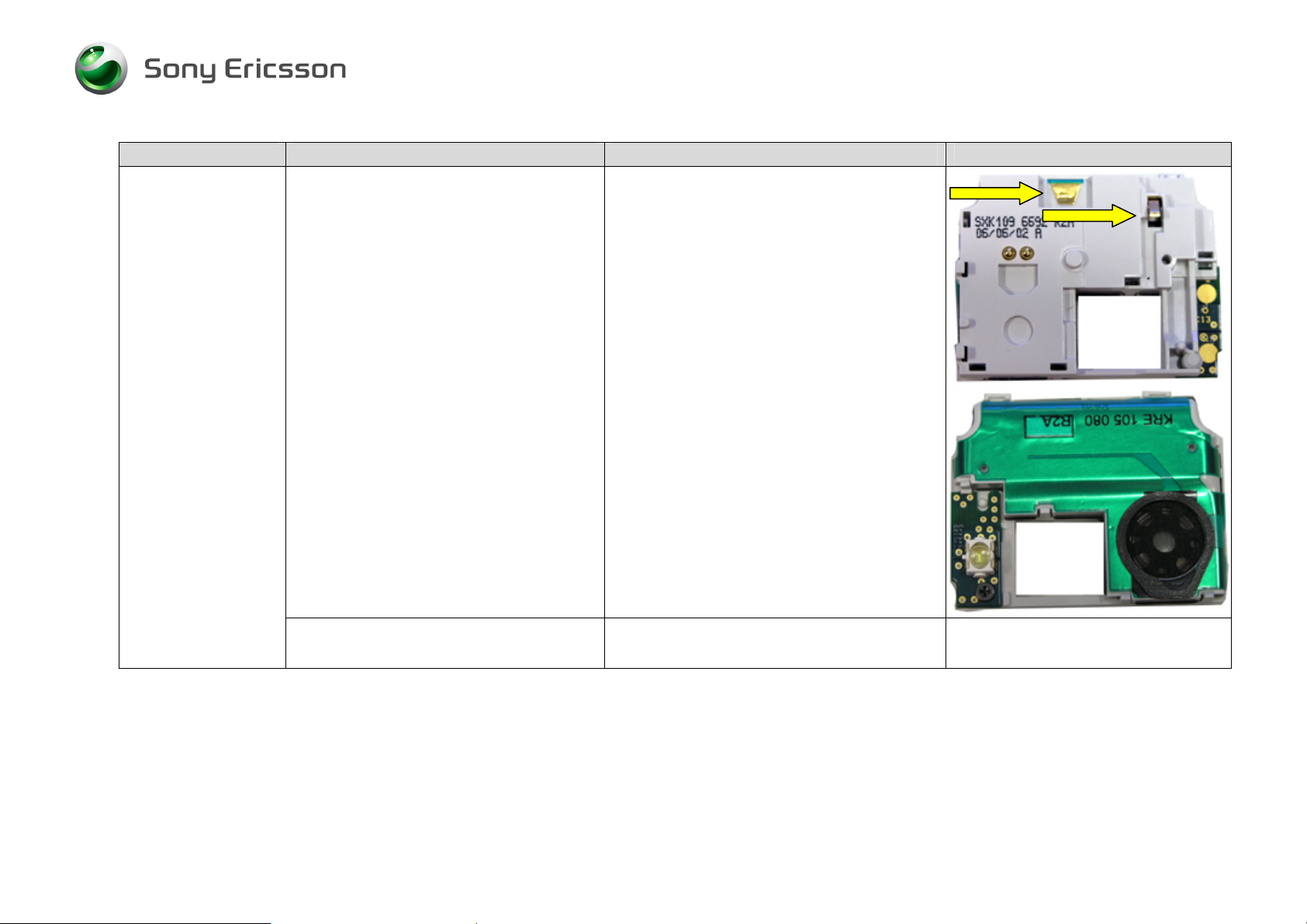
Visually inspect receiver’s external port
Visually inspect whether the main flex
film is properly connected to its
connector on the navigation key foil
assy
• If clogged – Clean or replace front.
• If improperly connected – Re-establish
proper connection.
• If main flex is damage – replace it.
4/000 21-1/FEA 209 544/104 A
Company Internal
© Sony Ericsson Mobile Communications AB
14(42)
Page 15

Trouble Shooting Guide, Mechanical
Problem Area Items to Check Repair Action Reference Image
Visually inspect whether the half to half
flex film is properly connected to its
connector on the navigation key foil
assy and the PCB
• If improperly connected – Re-establish
proper connection.
• If half to half flex is damage – Replace
it.
Main flex connector
If the issue has not been resolved !
• If BtB connector on the PCB is
damaged - Send to electrical repair.
• Replace receiver
Half to half flex connector
4/000 21-1/FEA 209 544/104 A
Company Internal
© Sony Ericsson Mobile Communications AB
15(42)
Page 16

Trouble Shooting Guide, Mechanical
Problem Area Items to Check Repair Action Reference Image
If the issue has not been resolved !
• Handle the unit according to local
directives.
Loudspeaker:
No sound or poor
quality sound
Before proceeding !
Visually inspect loudspeaker’s external
port
If the issue has not been resolved !
• Do software update content refresh.
Note: this problem will not be solved be
a regular software update.
Note: Software Update Content Refresh
will erase all user data.
• If clogged – Clean it.
• Replace loudspeaker box.
4/000 21-1/FEA 209 544/104 A
Company Internal
© Sony Ericsson Mobile Communications AB
16(42)
Page 17

Trouble Shooting Guide, Mechanical
Problem Area Items to Check Repair Action Reference Image
If the issue has not been resolved !
• Handle the unit according to local
directives.
4/000 21-1/FEA 209 544/104 A
Company Internal
© Sony Ericsson Mobile Communications AB
17(42)
Page 18

Trouble Shooting Guide, Mechanical
6 Key Problems
Problem Area
Keyboard
Numeric:
A key on the main
keyboard (1.2.3…)
is not functioning or
is intermittent
Items to Check
Visually inspect for debris between
keypad and numeric key foil assy, and
for damage to the keypad and the
numeric key foil assy.
If the issue has not been resolved !
If the issue has not been resolved !
Repair Action
• If damaged - Replace keypad and/or
key foil assy as necessary.
• Replace keypad numeric and/or key
foil assy, if it has not already been
replaced.
• Handle the unit according to local
directives.
Reference Image
4/000 21-1/FEA 209 544/104 A
Company Internal
© Sony Ericsson Mobile Communications AB
18(42)
Page 19

Trouble Shooting Guide, Mechanical
Problem Area
Keyboard
Navigation:
A key on the sub
Items to Check
Visually inspect for debris between
keypad and navigation key foil assy,
and for damage to the keypad and the
navigation key foil assy.
Repair Action
• If damaged - Replace keypad and/or
navigation key foil assy as necessary.
keyboard (navi
keys) is not
functioning or is
intermittent
Reference Image
4/000 21-1/FEA 209 544/104 A
Company Internal
© Sony Ericsson Mobile Communications AB
19(42)
Page 20

Trouble Shooting Guide, Mechanical
Problem Area
Items to Check
Visually inspect whether the main flex
film is properly connected to its
connector on both PCB’s
Repair Action
• If improperly connected – Re-establish
proper connection.
• If main flex is damage – Replace it.
• If any of the BtB connector on the
navigation key foil assy are damaged –
Replace navigation key foil assy.
Reference Image
4/000 21-1/FEA 209 544/104 A
Company Internal
© Sony Ericsson Mobile Communications AB
20(42)
Page 21

Trouble Shooting Guide, Mechanical
Problem Area
Items to Check
If the issue has not been resolved !
Repair Action
• Replace keypad, key foil assy and/or
navigation key foil assy, if it has not
already been replaced.
Reference Image
Main flex connector
Half to half flex connector
4/000 21-1/FEA 209 544/104 A
Company Internal
© Sony Ericsson Mobile Communications AB
If the issue has not been resolved !
• Handle the unit according to local
directives.
21(42)
Page 22

Trouble Shooting Guide, Mechanical
Problem Area
A & B keys
Items to Check
Visually inspect whether the main flex
film is properly connected to its
connector on the navigation key foil
assy
Repair Action
• If improperly connected – Re-establish
proper connection.
• If main flex is damage – replace it.
Reference Image
4/000 21-1/FEA 209 544/104 A
Company Internal
© Sony Ericsson Mobile Communications AB
22(42)
Page 23

Trouble Shooting Guide, Mechanical
Problem Area
Items to Check
Visually inspect whether the half to half
flex film is properly connected to its
connector on the navigation key foil
assy and the PCB
Repair Action
• If improperly connected – Re-establish
proper connection.
• If half to half flex is damage – Replace
it.
• If any of the BtB connector on the
navigation key foil assy are damaged –
Replace navigation key foil assy.
• If BtB connector on the PCB is
damaged - Send to electrical repair.
Reference Image
Main flex connector
Half to half flex connector
4/000 21-1/FEA 209 544/104 A
Company Internal
© Sony Ericsson Mobile Communications AB
If the issue has not been resolved !
• Handle the unit according to local
directives.
23(42)
Page 24

Trouble Shooting Guide, Mechanical
7 Slider Problems
Problem Area
Slider
The slider can not
open or close
Items to Check
Inspect whether the slider open and
close properly
If the display do not change when open
or close
Repair Action
• If there are any problems – replace the
slider
•
• If damaged – Replace it
Reference Image
4/000 21-1/FEA 209 544/104 A
Company Internal
© Sony Ericsson Mobile Communications AB
If the issue has not been resolved !
• Handle the unit according to local
directives.
24(42)
Page 25

Trouble Shooting Guide, Mechanical
8 Display Problems
Problem Area
Items to Check
Check whether the phone vibrates 10 to
15 seconds after pressing the power
key and whether the keypad illuminates
Before proceeding !
Repair Action
• If activation of the vibrator are not
detected, refer to the On/Off
Problems” chapter 4
• Do software update content refresh.
Note: this problem will not be solved be
a regular software update.
Note: Software Update Content Refresh
will erase all user data.
Reference Image
4/000 21-1/FEA 209 544/104 A
Company Internal
© Sony Ericsson Mobile Communications AB
25(42)
Page 26

r
Trouble Shooting Guide, Mechanical
Problem Area
Display
Items to Check
Visually inspect whether the LCD flex
film is properly connected to its
connector on the navigation keyfoil
assy
Repair Action
• If improperly connected – Re-establish
proper connection.
• If damage – Replace navigation keyfoil
assy or display as necessary.
Reference Image
LCD connecto
4/000 21-1/FEA 209 544/104 A
Company Internal
© Sony Ericsson Mobile Communications AB
26(42)
Page 27

Trouble Shooting Guide, Mechanical
Problem Area
Items to Check
Visually inspect whether the half to half
flex film is properly connected to its
connector on both PCB’s
Repair Action
• If improperly connected – Re-establish
proper connection.
• If half to half flex is damage – replace
it.
Reference Image
• If Half to half BtB connector is
damaged – Replace navigation keyfoil
assy.
Half to half flex connector
4/000 21-1/FEA 209 544/104 A
Company Internal
© Sony Ericsson Mobile Communications AB
27(42)
Page 28

Trouble Shooting Guide, Mechanical
Problem Area
Items to Check
If the issue has not been resolved !
Repair Action
• Replace the main LCD.
NOTE: Misuse is not covered by
warranty. Refer to chapter 1.2
If the issue has not been resolved !
• Handle the unit according to local
directives.
Reference Image
4/000 21-1/FEA 209 544/104 A
Company Internal
© Sony Ericsson Mobile Communications AB
28(42)
Page 29

Trouble Shooting Guide, Mechanical
9 Illumination Problems
Problem Area
Before proceeding !
LCD illumination
Key numeric
illumination:
Key navigation
illumination:
Items to Check
Refer to “Display” section under “Display Problems”
Refer to “Keyboard numeric ” section under “Key Problems”
Refer to “Keyboard navigation ” section under “Key Problems”
Repair Action
• Do software update content refresh.
Note: this problem will not be solved be
a regular software update.
Note: Software Update Content Refresh
will erase all user data.
Reference Image
4/000 21-1/FEA 209 544/104 A
Company Internal
© Sony Ericsson Mobile Communications AB
29(42)
Page 30

Trouble Shooting Guide, Mechanical
10 Alert Problems
Problem Area
Vibrator:
Items to Check
Before proceeding !
Visually inspect the vibrator pads on the
PCB
Visually inspect the vibrator
Repair Action
• Do software update content refresh.
Note: this problem will not be solved be
a regular software update.
Note: Software Update Content Refresh
will erase all user data.
• If dirty or oxidized – Clean them.
• If dirty or oxidized – Replace it.
• If damaged – Replace it.
Reference Image
Loudspeaker
4/000 21-1/FEA 209 544/104 A
Company Internal
© Sony Ericsson Mobile Communications AB
Refer to “loudspeaker” section under “Audio Problems”
30(42)
Page 31

Trouble Shooting Guide, Mechanical
11 SIM Problems
Problem Area
SIM undetected
(Insert SIM)
Unit indicates an
incorrect SIM is
inserted (Insert
correct SIM)
Items to Check
Visually inspect SIM holder
Check whether the phone is locked to a
particular carrier and whether the
correct carrier’s SIM is being used
If the issue has not been resolved !
Repair Action
• If dirty, oxidized or damaged – Replace
it.
• Use Correct Carrier SIM or test SIM.
• Handle the unit according to local
directives.
Reference Image
4/000 21-1/FEA 209 544/104 A
Company Internal
© Sony Ericsson Mobile Communications AB
31(42)
Page 32

Trouble Shooting Guide, Mechanical
12 Charging/Capacity Problems
Problem Area
Battery will not
charge
Items to Check
Visually inspect the contact pads of the
battery
Visually inspect the battery connector
Visually inspect the system connector
Repair Action
• If dirty or oxidized – Clean.
• If damaged – Replace battery.
• If dirty or oxidized – Clean.
• If damaged – Send to an electrical
repair location.
• If dirty or oxidized – Clean
Reference Image
4/000 21-1/FEA 209 544/104 A
Company Internal
© Sony Ericsson Mobile Communications AB
• If damaged – replace it.
Note: Remember to put back the dust
gasket system connector before the
system connector
32(42)
Page 33

Trouble Shooting Guide, Mechanical
If the issue has not been resolved !
• Handle the unit according to local
directives.
Battery looses
charge quickly/
standby time
seems short
Before proceeding !
Note: Some features noticeably
reduce the amount of standby time if
they are turned on. Some examples
are the back light (when on all the
time), Bluetooth and infrared.
If the issue has not been resolved !
If the issue has not been resolved !
• Do software update content refresh.
Note: this problem will not be solved be
a regular software update.
Note: Software Update Content Refresh
will erase all user data.
• Replace battery.
• Handle the unit according to local
directives.
4/000 21-1/FEA 209 544/104 A
Company Internal
© Sony Ericsson Mobile Communications AB
33(42)
Page 34

Trouble Shooting Guide, Mechanical
13 Camera Problems
Problem Area Items to Check Repair Action Reference Image
Camera rear
(Mega pixels)
Lines, marks,
blurred or
discolored picture/
Will not enter
camera menu
Visually inspect the camera lens
Visually inspect whether the camera is
properly connected to its socket on the
PCB.
• If scratched or damaged – Replace
upper case rear.
• If improperly connected – Re-establish
proper connection.
• If camera socket is damaged – Send to
electrical repair.
4/000 21-1/FEA 209 544/104 A
Company Internal
© Sony Ericsson Mobile Communications AB
34(42)
Page 35

Trouble Shooting Guide, Mechanical
Problem Area Items to Check Repair Action Reference Image
If the issue has not been resolved !
• Replace the camera rear.
Note: Remember to put back the
camera rubber when replacing the
camera.
Will not capture an
image
4/000 21-1/FEA 209 544/104 A
Company Internal
© Sony Ericsson Mobile Communications AB
If the issue has not been resolved !
Visually inspect for damage to the
camera keys
• Handle the unit according to local
directives.
• If damaged – Replace them.
35(42)
Page 36

Trouble Shooting Guide, Mechanical
Problem Area Items to Check Repair Action Reference Image
Visually inspect whether the camera is
properly connected to its socket on the
PCB.
If the issue has not been resolved !
• If improperly connected – Re-establish
proper connection.
• If camera socket is damaged – Send to
electrical repair
• Replace camera rear.
4/000 21-1/FEA 209 544/104 A
Company Internal
© Sony Ericsson Mobile Communications AB
If the issue has not been resolved !
• Handle the unit according to local
directives.
36(42)
Page 37

Trouble Shooting Guide, Mechanical
Problem Area Items to Check Repair Action Reference Image
Camera Front
(Video call camera)
Visually inspect the camera lens
Visually inspect whether the video call
camera flex film is properly connected
to its connector on the main flex film.
• If dirty – Clean camera lens.
• If scratched or damaged – Replace
sheet (Screw) Upper.
• If improperly connected – Re-establish
proper connection.
• If damage – Replace navigation key
foil assy or video call camera as
necessary.
4/000 21-1/FEA 209 544/104 A
Company Internal
© Sony Ericsson Mobile Communications AB
37(42)
Page 38

Trouble Shooting Guide, Mechanical
Problem Area Items to Check Repair Action Reference Image
Visually inspect whether the half to half
flex film is properly connected to its
connector on both PCB’s
• If improperly connected – Re-establish
proper connection.
• If half to half flex is damage – Replace
it.
Main flex connector
• If any of the BtB connectors on the
navigation key foil assy are damaged –
Replace navigation key foil assy.
• If main BtB connector on the PCB is
damaged – Send to electrical repair
Half to half flex connector
4/000 21-1/FEA 209 544/104 A
Company Internal
© Sony Ericsson Mobile Communications AB
38(42)
Page 39

Trouble Shooting Guide, Mechanical
Problem Area Items to Check Repair Action Reference Image
If the issue has not been resolved !
If the issue has not been resolved !
• Replace the camera front.
• Replace the main flex film, navigation
key foil assy and the video call camera
if not always replaced.
LED flash
4/000 21-1/FEA 209 544/104 A
Company Internal
© Sony Ericsson Mobile Communications AB
Visually inspect the flash LED
• If no flash light – Replace LED- flash
module
Note: Remember to put back the flash
reflector when replacing flash LED.
39(42)
Page 40

Trouble Shooting Guide, Mechanical
14 Data Communication Problems
Problem Area Items to Check Repair Action Reference Image
Will not connect
with a functional
Bluetooth device
Visually inspect the system connector
pads for dirt.
If the issue has not been resolved !
• If dirty – Clean it.
• Replace the BT antenna
4/000 21-1/FEA 209 544/104 A
Company Internal
© Sony Ericsson Mobile Communications AB
If the issue has not been resolved !
• Handle the unit according to local
directives.
40(42)
Page 41

Trouble Shooting Guide, Mechanical
15 Software Problems
• If there are problems with the response of the keypad commands, spelling errors in the menu or the phone hang, if they are not
related to mechanical damage, make a master reset and flash the phone with the latest software from EMMA III.
• Checking the software revision can be done in the Service info, see chapter Service functions in the software.
Choose: Service info / SW information.
The Software revision and date will be shown in the display.
Note: Do Software Update Content Refresh before sending the unit to a higher level. Do not scrap a phone that hasn’t been
upgraded with Software Update Content Refresh.
If the failure still occurs, handle the unit according to the local directives.
4/000 21-1/FEA 209 544/104 A
Company Internal
© Sony Ericsson Mobile Communications AB
41(42)
Page 42

Trouble Shooting Guide, Mechanical
16 Revision History
Rev. Date Changes / Comments
A 2006-09-20 Initial release
4/000 21-1/FEA 209 544/104 A
Company Internal
© Sony Ericsson Mobile Communications AB
42(42)
 Loading...