

Page 1

Go/No Go Test Script Specification
, Electrical
Go/No Go Test Script Specification,
Electrical
Applicable for:W760 and W760c
Contents
...
General
1
...
Test Sequence - Radiated
2
...
Test Sequence - Conducted
3
1.1
1.2
1.3
1.4
1.5
1.6
2.1
2.2
2.3
2.4
2.5
2.6
2.7
2.8
2.9
2.10
2.11
2.12
2.13
2.14
2.15
2.16
2.17
2.18
2.19
2.20
2.21
2.22
2.23
3.1
3.2
3.3
3.4
3.5
3.6
................................................................................................................................
About This Document
Script Requirements
Traffic Channel (TCH) Allocation Table
Power Level Allocation Table
Test Limits
Attenuation Factors
Initializing and Call Setup
Audio Loopback
GSM 85
GSM 850 Mid TCH Measurements
GSM 850 High TCH Measurements
GSM 1900 Low TCH Measurements
GSM 1900 Mid TCH Measurements
GSM 1900 High TCH Measurements
GSM 1800 Low TCH Measurements
GSM 1800 Mid TCH Measurements
GSM 1800 High TCH Measurements
GSM 900 Low TCH Measurements
GSM 900 Mid TCH Measurements
GSM 900 High TCH Measurements
UMTS 850 Low TCH Measurements (W760 only)
UMTS 850 Mid TCH Measurements (W760 only)
UMTS 850 High TCH Measurements(W760 only)
UMTS 1900 Low TCH Measurements (W760 only)
UMTS 1900 Mid TCH Measurements (W760 only)
UMTS 1900 High TCH Measurements (W760 only)
UMTS 2100 Low TCH Measurements (W760 only)
UMTS 2100 Mid TCH Measurements (W760 only)
UMTS 2100 High TCH Measurements (W760 only)
Initializing and Call Setup
Audio Loopback
GSM 850 Low TCH Measurements
GSM 850 Mid TCH Measureme
GSM 850 High TCH Measurements
GSM 1900 Low TCH Measurements
........................................................................................................
0 Low TCH Measurements
.....................................................................................
.......................................................................................
.......................................................
........................................................................
.........................................................................................
..............................................................................................
...............................................................................
...............................................................................................
.............................................................
..............................................................
............................................................
...........................................................
............................................................
..........................................................
.........................................................10
..........................................................10
........................................................11
...........................................................11
............................................................12
..........................................................12
..................................13
...................................13
...................................14
................................14
.................................15
...............................15
................................16
.................................16
...............................17
........................................................................................18
.............................................................................18
.............................................................................................19
...........................................................19
nts
............................................................19
..........................................................20
.........................................................20
3
3
3
4
4
5
5
5
5
7
7
7
8
8
9
9
1211-1568 4
Company Internal
Sony Ericsson Mobile Communications AB
Page 2

3.7
GSM 1900 Mid TCH Measurements
3.8
GSM 1900 High
3.9
GSM 1800 Low TCH Measurements
3.10
GSM 1800 Mid TCH Measurements
3.11
GSM 1800 High TCH Measurements
3.12
GSM 900 Low TCH Measurements
3.13
GSM 900 Mid TCH Measurements
3.14
GSM 900 High TCH Measurements
3.15
UMTS 850 Low TCH Measurements (W760 only)
3.16
UMTS 850 Mid TCH Measurements (W760 only)
3.17
UMTS 850 High TCH Measurements (W760 only)
3.18
UMTS 1900 Low TCH Measurements (W760 only)
3.19
UMTS 1900 Mid TCH Measurements (W760 only)
3.20
UMTS 1900 High TCH Measurements (W760 only)
3.21
UMTS 2100 Low TCH Measurements (W760 only)
3.22
UMTS 2100 Mid TCH Measurements (W760 only)
3.23
UMTS 2100 High TCH Measurements (W760 only)
4...
Attenuation Factors
4.1
Radiated Loss Values for W760 (AT&T
4.2
Radiated Loss Values for W760
4.3
Radiated Loss Values for W760c
4.4
Conducted Loss Values for W760
4.5
Cond
5...
Revision history
Go/No Go Test Script Specification, Electrical
..........................................................21
TCH Measurements
.......................................................................................................30
ucted Loss Values for W760c
.............................................................................................................34
........................................................21
.........................................................22
..........................................................22
........................................................23
...........................................................23
............................................................24
..........................................................24
..................................25
...................................25
..................................26
................................26
.................................27
...............................27
................................28
.................................28
...............................29
and Rogers)
.................................................................31
...............................................................32
..............................................................33
............................................................33
..............................30
1211-1568 4
Company Internal Sony Ericsson Mobile Communications AB
2(34)
Page 3

1 General
1.1 About This Document
This document contains the test requirements for a 3G GSM (850/900/1800/1900) and
UMTS (850/190
cable (Conducted) connection. These test sequences should be used as an arrival and
verification test of radio functionality.
Tests are done in signaling mode, i.e. a call has been estab
The test instrument controls the transceiver unit. RF performance is measured with an
antenna coupler or the direct line connection, whichever method is selected.
1.2 Script Requirements
0/2100) pocket transceiver using an antenna coupler (Radiated) or RF
Go/No Go Test Script Specification, Electrical
lished to the test instrument.
NOTE!
The test should be designed so those user
perform accurate testing.
The measurements should run automatically, though a certain amount of manual
work is included (and mandatory), such as MS call setup (i.e. dialling number).
It should be possible to print
It should be possible to change the channels used in testing due to possible local
radio interference. The ranges for these settings are specified under the
Allocation Table
All functions and settings should be
cannot directly change them. (For example, a password or encrypted settings file.)
The attenuation factors that should be used are stated in section 4. The test
inst
rument must be capable of using different attenuation factors for RX and TX. It
must also be possible to use various attenuation factors for different channels in
each band.
Any setups other than the one stated in this document must be
discussed a
.
or store the measurement results.
protected in such a manner that the end-user
nd exempted by Sony Ericsson to be approved.
s with little or no system expertise can
Channel
1211-1568 4
Company Internal Sony Ericsson Mobile Communications AB
3(34)
Page 4
Go/No Go Test Script Specification, Electrical
1.3 Traffic Channel (TCH) Allocation Table
Band
GSM 850
GSM 850
GSM 850
GSM 900
GSM 900
GSM 900
GSM
1800
GSM 1800
GSM 1800
GSM 1900
GSM 1900
GSM 1900
WCDMA 850
WCDMA 850
WCDMA 850
Ch definition
Low
Mid
High
Low
Mid
High
Low
Mid
High
Low
Mid
High
Low
Mid
High
Any ARFCN of:
128-132
187-191
247-251
975-979
36-40
120-124
512-516
697-701
881-885
512-516
658-662
806-810
4132
4175
4233
WCDMA 1900
WCDMA 1900
WCDMA 1900
WCDMA 2100
WCDMA 2100
WCDMA 2100
Low
Mid
High
Low
Mid
High
1.4 Power Level Allocation Table
Band
GSM 850
GSM 850
GSM 850
GSM 900
GSM 900
GSM 900
GSM 1800/1900
GSM 1800/1900
GSM 1800/1900
PL
definition
Lowest
Mid
Highest
Lowest
Mid
Highest
Lowest
Mid
8
Highest
7
5
0
9262
9400
9538
9612
9750
9888
Power level (PL)
19
12
19
12
15
1211-1568 4
Company Internal Sony Ericsson Mobile Communications AB
4(34)
Page 5
1.5 Test Limits
The test limits for each measurement are specified in the Sequence Tables.
1. Since a coupler introduces higher measurement inaccuracy, some
measurements in the radiated
stated in the 3GPP specifications.
2. The conducted limits conform to the phase 3GPP specification.
1.6 Attenuation Factors
The different scripts must be configured with the correct attenuation factors and named
after t
he product that they are designed to test. The attenuation factors to be used are
stated in section
4.
Go/No Go Test Script Specification, Electrical
test sequences may have wider limits than
2 Test Sequence - Radiated
2.1 Initializing and Call Setup
Parameter
BCCH
TCH
TX pow
RF output power
System
er level
-40
Value
Mid
Mid
High
GSM 850
Unit
Ch
Ch
PL
dBm
1211-1568 4
Company Internal Sony Ericsson Mobile Communications AB
5(34)
Page 6
2.1.1 Sequence
1. Initialize instrument.
2. Insert a test-USIM and attach a fully charged standard battery to the
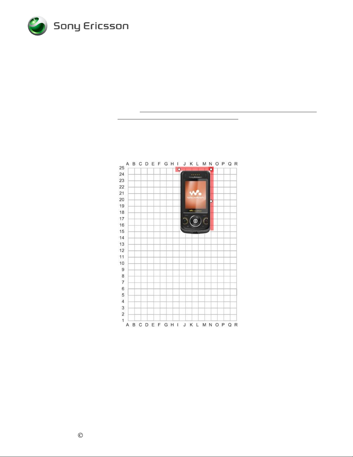
3. Position the mobile in the coupler according to the picture.
Go/No Go Test Script Specification, Electrical
mobile.
there is a high risk for incorrect test results.
It’s very important that a fully charged battery is used otherwise
Rohde & Schwarz Shield Box and Coupler (N25)
4. Turn on the mobile and wait for registration.
5. Set up a call to the instrument or l
6. Close the lid on the shielding box.
1211-1568 4
Company Internal Sony Ericsson Mobile Communications AB
et the instrument call the MS.
6(34)
Page 7
Go/No Go Test Script Specification, Electrical
2.2 Audio Loopback
1. Set power level to high.
2. Activate audio loopback in the instrument.
3. Operator must acknowledge passed or failed before the test is continued.
2.3 GSM 850 Low TCH Measurements
Pa
rameter
TCH
TX power level
RF output power
System
-68
2.3.1 GSM 850 Low TCH Test Limits
Measurement
TX power
RMS Phase error
Rx Level
Rx Quality
0-3
Test Limits
29 +/
0 +/
34-50
Value
Low
High
GSM 850
-4
-5
Unit
Ch
PL
dBm
Unit
dB
deg
dB
Units
2.4 GSM 850
Mid TCH Measurements
Parameter
TCH
TX power level
RF output power
System
-
2.4.1 GSM 850 Mid TCH Test Limits
Measurement
TX power
RMS Phase error
Peak Phase error
Freq error
Rx Level
Rx Quality
1211-1568 4
Company Internal Sony Ericsson Mobile Communications AB
2-14
0-3
Test Limits
+/-0.1 ppm
GSM 850
19 +/
-5
0 +/
-5
0 +/-20
Value
Mid
Mid
102
deg
Unit
Ch
PL
dBm
Unit
dB
deg
Hz
dB
Units
7(34)
Page 8
Go/No Go Test Script Specification, Electrical
2.5 GSM 850 High TCH Measurements
Parameter
TCH
TX power level
RF output power
System
-68
2.5.1 GSM 850 High TCH Test Limits
Measurement
TX power
RMS Phase error
Test Limits
GSM 850
5 +/
-7
0 +/
-5
Value
High
Low
Unit
Ch
PL
dBm
Unit
deg
dB
2.6 GSM 1900 Low TCH Measurements
Parameter
TCH
TX power level
RF output power
System
-68
2.6.1 GSM 1900 Low TCH Test Limits
Measurement
TX power
RMS Phase Error
Rx Level
RX Quality
0-3
Test Limits
Value
GSM 1900
0 +/
-7
0 +/
-5
34-50
Low
Low
Unit
Ch
PL
dBm
Unit
deg
Units
dB
dB
1211-1568 4
Company Internal Sony Ericsson Mobile Communications AB
8(34)
Page 9
Go/No Go Test Script Specification, Electrical
2.7 GSM 1900 Mid TCH Measurements
Parameter
TCH
TX power level
RF output power
System
-
2.7.1 GSM 1900 Mid TCH Test Limits
Measure
TX power
RMS Phase error
Peak Phase error
Freq. error
Rx Level
Rx Quality
ment
2-14
0-3
Test Limits
+/-0.1 ppm
GSM 1900
14 +/
-5
0 +/
-5
0 +/-20
Value
Mid
Mid
102
Unit
Ch
PL
dBm
Unit
deg
deg
Units
dB
Hz
dB
2.8 GSM 1900 High TCH Measurements
Parameter
TCH
TX power level
RF output power
System
H
-68
2.8.1 GSM 1900 High TCH Test Limits
Measurement
TX power
RMS Phase error
Test Limits
30 +/
0 +/
Value
High
igh
GSM 1900
-4
-5
Unit
Ch
PL
dBm
Unit
deg
dB
1211-1568 4
Company Internal Sony Ericsson Mobile Communications AB
9(34)
Page 10
Go/No Go Test Script Specification, Electrical
2.9 GSM 1800 Low TCH Measurements
Parameter
TCH
TX power level
RF output power
System
-68
2.9.1 GSM 1800 Low TCH Test Limits
Measurement
TX power
RMS Phase Error
Rx Level
RX Quality
0-3
Test Limits
30 +/
Value
GSM 1800
-4
0 +/
-5
34-50
Low
High
Unit
Ch
PL
dBm
Unit
deg
Units
dB
dB
2.10 GSM 1800 Mid TCH Measurements
Parameter
TCH
TX power level
RF output power
System
-
2.10.1 GSM 1800 Mid TCH Test Limits
Measurement
TX power
RMS Phase error
Peak Phase error
Freq. error
Rx Level
Rx Quality
2-14
0-3
Test Limits
+/-0.1 ppm
GSM 1800
14 +/
-5
0 +/
-5
0 +/-20
Value
Mi
d
Mid
102
Unit
Ch
PL
dBm
Unit
deg
deg
Units
dB
Hz
dB
1211-1568 4
Company Internal Sony Ericsson Mobile Communications AB
10(34
)
Page 11
Go/No Go Test Script Specification, Electrical
2.11 GSM 1800 High TCH Measurements
Parameter
TCH
TX power level
RF output power
System
2.11.1 GSM 1800 High TCH Test Limits
TX power
RMS Phase
Measurement
-68
error
Test Limits
0 +/
0 +/
Value
High
Low
GSM 1800
-7
-5
Unit
Ch
PL
dBm
Unit
deg
dB
2.12 GSM 900 Low TCH Measurements
Parameter
TCH
TX power level
RF output power
System
2.12.1 GSM 900 Low TCH Test Limits
TX power
RMS Phase error
Rx Level
Rx Quality
Measurement
-68
0-3
Test Limits
33 +/
0 +/
34-50
Value
Low
High
GSM 900
-4
-5
Unit
Ch
PL
dBm
Unit
dB
deg
dB
Units
1211-1568 4
Company Internal Sony Ericsson Mobile Communications AB
11(34
)
Page 12

Go/No Go Test Script Specification, Electrical
2.13 GSM 900 Mid TCH Measurements
Parameter
TCH
TX power level
RF output power
System
-
2.13.1 GSM 900 Mid TCH Test Limits
Measurement
TX power
RMS Phase error
Peak Phase error
Freq error
Rx Level
Rx Quality
2-14
0-3
Value
Mid
Mid
102
GSM 900
Test Limits
19 +/
-5
0 +/
-5
0 +/-20
+/-0.1 ppm
Unit
Ch
PL
dBm
Unit
deg
deg
Units
dB
Hz
dB
2.14 GSM 900 High TCH Measurements
Parameter
TCH
TX power level
RF output power
System
-68
2.14.1 GSM 900 High TCH Test Limits
Measurement
TX power
RMS Phase error
1211-1568 4
Company Internal Sony Ericsson Mobile Communications AB
Value
High
Low
GS
M 900
Test Limits
5 +/
0 +/
-7
-5
Unit
Ch
PL
dBm
Unit
deg
dB
12(34
)
Page 13

Go/No Go Test Script Specification, Electrical
2.15 UMTS 850 Low TCH Measurements (W760 only)
TCH
Power Level
RF out
2.15.1 UMTS 850 Lo
Tx Maximum Output Power
EVM
Frequency Error
Tx Adjacent Channel Level Ratio +/-5MHz
Tx Adjacent Channel Level Ratio +/- 10MHz
Parameter
-
w TCH Test Limits
Measurement
-
Value
Low
Maximum
93
Test Limits
-46
19 to 27
17.5 max
0.1 to 0.1
-
36
Channel
%
Unit
dBm
dBm
Unit
dBm
ppm
dBc
dBc
2.16 UMTS 850 Mid TC
TCH
Power Level
RF out
2.16.1 UMTS 850 Mid TCH Test Limits
Tx Maximum Output Power
EVM
Frequency Error
Tx Adjacent Channel Level Ratio +/- 5MHz
Tx Adjacent Channel Level Ratio +/- 10MHz
Rx Reference Sensitivity Level* (RF out: -104) -0.1 to 0.1
H Measurements (W760 only)
Parameter
-
Measurement
-
Value
Mid
Maximum
93 (* -104)
Test Limits
19 to 27
17.5 max
0.1 to
-36
-46
0.1
Unit
Channel
dBm
dBm
Unit
dBm
%
ppm
dBc
dBc
%
1211-1568 4
Company Internal Sony Ericsson Mobile Communications AB
13(34
)
Page 14

Go/No Go Test Script Specification, Electrical
2.17 UMTS 850 High TCH Measurements(W760 only)
Parameter
TCH
Power Level
RF out
-
2.17.1 UMTS 850 High TCH Test Limits
Tx Maximum Output Power
EVM
Frequency Error
Tx Adjacent Channel Level Ratio +/- 5MHz
Tx Adja
cent Channel Level Ratio +/- 10MHz
Measurement
-
Maximum
Value
High
93
-36
-
Test Limits
19 to 27
17.5 max
0.1 to 0.1
46
Channe
%
Unit
dBm
dBm
Unit
dBm
degree
dBc
dBc
l
2.18 UMTS 1900 Low TCH Measurements (W760 only)
Parameter
TCH
Power Level
RF out
-
2.18.1 UMTS 1900 Low TCH Test Limits
Tx Maximum Output Power
EVM
Frequency Error
Tx Adjacent Channel Level Ratio +/- 5MHz
Tx Adjacent Channel Level Ratio +/- 10MHz
Measurement
-
Value
Low
Maximum
93
Test Limits
19 to 27
17.5 max
0.1 to 0.1
-36
-46
Unit
Channel
dBm
dBm
%
Unit
dBm
ppm
dBc
dBc
1211-1568 4
Company Internal Sony Ericsson Mobile Communications AB
14(34
)
Page 15

Go/No Go Test Script Specification, Electrical
2.19 UMTS 1900 Mid TCH Measurements (W760 only)
Parameter
TCH
P
ower Level
RF out
-
2.19.1 UMTS 1900 Mid TCH Test Limits
Tx Maximum Output Power
EVM
Frequency Error
Tx Adjacent Channel Level Ratio +/- 5MHz
Tx Adjac
Rx Reference Sensitivity Level* (RF out: -104) -0.1 to 0.1
ent Channel Level Ratio +/- 10MHz
Measurement
-
Value
Mid
Maximum
93 (* -104)
Test Limits
19 to 27
17.5 max
0.1 to 0.1
-36
-46
Channel
%
%
Unit
dBm
dBm
Unit
dBm
ppm
dBc
dBc
2.20 UMTS 1900 High TCH Measurements (W760 only)
Parameter
TCH
Power Level
RF out
-93
2.20.1 UMTS 1900 High TCH Te
Tx Maximum Output Power
EVM
Frequency Error
Tx Adjacent Channel Level Ratio +/- 5MHz
Tx Adjacent Channel Level Ratio +/- 10MHz
st Limits
Measurement
-
Maximum
Value
High
-36
-46
Test Limits
19 to 27
17.5 max
0.1 to 0.1
Unit
Channel
dBm
dBm
%
degree
Unit
dBm
dBc
dBc
1211-1568 4
Company Internal Sony Ericsson Mobile Communications AB
15(34
)
Page 16

2.21 UMTS 2100 Low TCH Mea
Parameter
TCH
Power Level
RF out
-
2.21.1 UMTS 2100 Low TCH Test Limits
Tx Maximum Output Power
EVM
Frequency Error
Tx
Adjacent Channel Level Ratio +/- 5MHz
Tx Adjacent Channel Level Ratio +/- 10MHz
Measurement
-
surements (W760 only)
Go/No Go Test Script Specification, Electrical
Maximum
Value
Low
93
-36
-46
Test Limits
19 to 27
17.5 max
0.1 to 0.1
Unit
Channel
dBm
dBm
Unit
%
dBm
ppm
dBc
dBc
2.22 UMTS 2100 Mid TCH Measurements (W760 only)
Parameter
TCH
Power Level
RF out
-
2.22.1 UMTS 2100 Mid TCH Test
Tx Maximum Output Power
EVM
Frequency Error
Tx Adjacent Channel Level Ratio +/- 5MHz
Tx Adjacent Channel Level Ratio +/- 10MHz
Rx Reference Sensitivity Level
Limits
Measurement
-
* (RF out: -104) -0.1 to 0.1
Value
Mid
Maximum
93 (* -104)
Test Limits
19 to 27
17.5 max
0.1 to 0.1
-36
-46
Channel
%
%
Unit
dBm
dBm
Unit
dBm
ppm
dBc
dBc
1211-1568 4
Company Internal Sony Ericsson Mobile Communications AB
16(34
)
Page 17

Go/No Go Test Script Specification, Electrical
2.23 UMTS 2100 High TCH Measurements (W760 only)
Parameter
TCH
Power Level
RF out
-
2.23.1 UMTS 2100 High TCH Test Limits
Tx Maximum Output Power
EVM
Frequency Error
Tx Adjacent Channel Level Ratio +/- 5MHz
Tx Adjacent Channel Level Ratio +/- 10MHz
Measurement
-
Maximum
Value
High
93
-36
-46
Test Limits
19 to 2
17.5 max
0.1 to 0.1
7
Unit
Channel
dBm
dBm
%
degree
Unit
dBm
dBc
dBc
2.23.2 Call Disconnect Sequence
1. Disconnect call.
2. End test.
1211-1568 4
Company Internal Sony Ericsson Mobile Communications AB
17(34
)
Page 18

3 Test Sequence - Conducted
3.1 Initializing a
3.1.1 Sequence
1. Initialize instrument
2. Insert a test-SIM and attach a fully charged standard battery to the mobile.
nd Call Setup
Parameter
BCCH
TCH
TX power level
RF output power
System
It’s very important
high risk for incorrect test results. A dummy battery can also be used.
-40
that a fully charged battery is used otherwise there is a
Go/No Go Test Script Specification, Electrical
Value
Mid
Mid
High
GSM 850
Unit
Ch
Ch
PL
dBm
3. Remove the Battery cover and Antenna plug from the back of the handset and
connect the mobile to the RF fixture according to
4. Turn on the mobile and wait for registration.
5. Set up a call to the instrument or let the instrument call the MS.
the picture.
1211-1568 4
Company Internal Sony Ericsson Mobile Communications AB
18(34
)
Page 19

Go/No Go Test Script Specification, Electrical
3.2 Audio Loopback
1.
Set power level to high.
2.
Activate audio loopback in the instrument.
3.
Operator must acknowledge passed or fai
led before the test is continued.
3.3 GSM 850 Low TCH Measurements
Parameter
TCH
TX power level
RF output power
System
-68
3.3.1 GSM 850 Low TCH Test Limits
Measurement
TX power
RMS Phase er
Rx Level
Rx Quality
ror
0-3
Test Limits
29 +/
0 +/
36-48
Value
Low
High
GSM 850
-2
-5
Unit
Ch
PL
dBm
Unit
dB
deg
dB
Units
3.4 GSM 850 Mid TCH Measurements
Parameter
TCH
TX power level
RF output power
System
3.4.1 GSM 850 Mid TCH Test Limits
Measurement
TX power
RMS Phase error
Peak Phase error
Freq error
Rx Level
Rx Quality
1211-1568 4
Company Internal Sony Ericsson Mobile Communications AB
-
4-12
0-3
Test Limits
+/-0.1 ppm
GSM 850
19 +/
-3
0 +/
-5
0 +/-20
Value
Mid
Mid
102
Unit
Ch
PL
dBm
Unit
deg
deg
Units
dB
Hz
dB
19(34
)
Page 20

Go/No Go Test Script Specification, Electrical
3.5 GSM 850 High TCH Measurements
Parameter
TCH
TX power level
RF output power
Sy
stem
3.5.1 GSM 850 High TCH Test Limits
Measurement
TX power
RMS Phase error
-68
Test Limits
GSM 850
5 +/
-5
0 +/
-5
Value
High
Low
Unit
Ch
PL
dBm
Unit
deg
dB
3.6 GSM 1900 Low TCH Measurements
Parameter
TCH
TX power level
RF output power
System
3.6.1 GSM 1900 Low TCH Test Limits
TX power
RMS Phase error
Rx Level
RX Quality
Measurement
-68
0-3
Test Limits
Value
GSM 1900
0 +/
-5
0 +/
-5
36-48
Low
Low
Unit
Ch
PL
dBm
Unit
deg
Units
dB
dB
1211-1568 4
Company Internal Sony Ericsson Mobile Communications AB
20(34
)
Page 21

Go/No Go Test Script Specification, Electrical
3.7 GSM 1900 Mid TCH Measurements
Parameter
TCH
TX power level
RF output power System
3.7.1 GSM 1900 Mid TCH Test Limits
TX power
RMS Phase error
Peak Phase error
Freq. error
Rx Level
Rx Quality
Measurement
4-12
0-3
Test Limits
+/-0.1 ppm
GSM 1900
14 +/
-3
0 +/
-5
0 +/-20
Value
Mid
Mid
102
Unit
Ch
PL
dBm
Unit
deg
deg
Units
dB
Hz
dB
3.8 GSM 1900 High TC
TCH
TX power level
RF output power
System
3.8.1 GSM 1900 High TCH Test Limits
TX power
RMS Phase error
Measurement
H Measurements
Parameter
-68
Value
High
High
GSM 1900
Test Limits
30 +/
-2
0 +/
-5
Unit
Ch
PL
dBm
Unit
deg
dB
1211-1568 4
Company Internal Sony Ericsson Mobile Communications AB
21(34
)
Page 22

3.9 GSM 1800 Low TCH Measure
Parameter
TCH
TX power level
RF output power
System
-68
3.9.1 GSM 1800 Low TCH Test Limits
Measurement
TX power
RMS Phase Error
Rx Level
RX Quality
0-3
Go/No Go Test Script Specification, Electrical
ments
Value
Low
High
GSM 1800
Unit
Ch
PL
dBm
Test Limits
30 +/
0 +/
36-48
-2
-5
Unit
dB
deg
dB
Units
3.10 GSM 1800 Mid TCH Measurements
Parameter
TCH
TX power level
RF output power
System
-
3.10.1 GSM 1800 Mid TCH Test Limits
Measurement
TX power
RMS Phase error
Peak Phase
Freq. error
Rx Level
Rx Quality
error
4-12
0-3
Test Limits
+/-0.1 ppm
GSM 1800
14 +/
-3
0 +/
-5
0 +/-20
Value
Mid
Mid
102
Unit
Ch
PL
dBm
Unit
deg
deg
Units
dB
Hz
dB
1211-1568 4
Company Internal Sony Ericsson Mobile Communications AB
22(34
)
Page 23

Go/No Go Test Script Specification, Electrical
3.11 GSM 1800 High TCH Measurements
Parameter
TCH
TX power level
RF output power
System
3.11.1 GSM 1800 High TCH Test Limits
TX power
RMS Phase error
Measurement
-68
Test Limits
0 +/
0 +/
Value
High
Low
GSM 1800
-5
-5
Unit
Ch
PL
dBm
Unit
deg
dB
3.12 GSM 900 Low TCH Measurements
Parameter
TCH
TX power level
RF output power
System
3.12.1 GSM 900 Low TCH Test Limits
TX power
RMS Phase error
Rx Level
Rx Quality
Measurement
-68
0-3
Te
Value
GSM 900
st Limits
33 +/
-2
0 +/
-5
36-48
Low
High
Unit
Ch
PL
dBm
Unit
deg
Units
dB
dB
1211-1568 4
Company Internal Sony Ericsson Mobile Communications AB
23(34
)
Page 24

Go/No Go Test Script Specification, Electrical
3.13 GSM 900 Mid TCH Measurements
TCH
TX power level
RF output power
System
3.13.1 GSM 900 Mid T
TX power
RMS Phase error
Peak Phase error
Freq error
Rx Level
Rx Quality
Parameter
-
CH Test Limits
Measurement
4-12
0-3
Value
Mid
Mid
102
GSM 900
Test Limits
19 +/
-3
0 +/
-5
0 +/-20
+/-0.1 ppm
Unit
Ch
PL
dBm
Unit
deg
deg
Units
dB
Hz
dB
3.14 GSM 900 High TCH Measurements
Parameter
TCH
TX power level
RF output power
System
-68
3.14.1 GSM 900 High TCH Test Limits
Measurement
TX power
RMS Phase error
Test Limits
GSM 900
5 +/
-5
0 +/
-5
Value
High
Low
Unit
Ch
PL
dBm
Unit
deg
dB
1211-1568 4
Company Internal Sony Ericsson Mobile Communications AB
24(34
)
Page 25

Go/No Go Test Script Specification, Electrical
3.15 UMTS 850 Low TCH Measurements (W760 only)
Parameter
TCH
Power Level
RF out
-
3.15.1 UMTS 850 Low TCH Test Limits
Tx Maximum Output Power
EVM
Frequency Error
Tx Adjacent Channel Level Ratio +/- 5MHz
Tx Ad
jacent Channel Level Ratio +/- 10MHz
Measurement
-
Value
Low
Maximum
93
Test Limits
21 to 25
17.5 max
0.1 to 0.1
-36
-46
Channel
%
Unit
dBm
dBm
Unit
dBm
ppm
dBc
dBc
3.16 UMTS 850 Mid TCH Measurements (W760 only)
Parameter
TCH
Power Level
RF out
-
3.16.1 UMTS 850 Mid TCH Test Limits
Tx Maximum Outpu
EVM
Frequency Error
Tx Adjacent Channel Level Ratio +/- 5MHz
Tx Adjacent Channel Level Ratio +/- 10MHz
Rx Reference Sensitivity Level* (RF out: -104) -0.1 to 0.1
Measurement
t Power
-
Value
Mid
Maximum
93 (* -104)
Test Limits
21 to 25
17.5 max
0.1 to 0.1
-36
-46
%
%
Unit
Channel
dBm
dBm
Unit
dBm
ppm
dBc
dBc
1211-1568 4
Company Internal Sony Ericsson Mobile Communications AB
25(34
)
Page 26

3.17 UMTS 850 High TCH
Parameter
TCH
Power Level
RF out
-
3.17.1 UMTS 850 High TCH Test Limits
Tx Maximum Output Power
EVM
Frequency Error
Tx Adjacent Channel Level Ratio +/- 5MHz
Tx Adjacent Channel Level Ratio +/- 10MHz
Measurements (W760 only)
Measurement
-
Go/No Go Test Script Specification, Electrical
Value
High
Maximum
93
-36
-46
Test Limits
21 to 25
17.5 max
0.1 to 0.1
Unit
Channel
dBm
dBm
Unit
%
dBm
degree
dBc
dBc
3.18 UMTS 1900 Low TCH Measurements (W760 only)
Parameter
TCH
Power Level
RF out
-
3.18.1 UMTS 1900 Low TCH Test
Tx Maximum Output Power
EVM
Frequency Error
Tx Adjacent Channel Level Ratio +/- 5MHz
Tx Adjacent Channel Level Ratio +/- 10MHz
Limits
Measurement
-
Value
Low
Maximum
93
Test Limits
21 to 25
17.5 max
0.1 to 0.1
-36
-46
Unit
Channel
dBm
dBm
%
Unit
dBm
ppm
dBc
dBc
1211-1568 4
Company Internal Sony Ericsson Mobile Communications AB
26(34
)
Page 27

3.19 UMTS 1900 Mid TCH Measur
Parameter
TCH
Power Level
RF out
-
3.19.1 UMTS 1900 Mid TCH Test Limits
Tx Maximum Output Power
EVM
Frequency Error
Tx Adjacent Channel Level Ratio +/- 5MHz
Tx Adjacent Channel Level Ratio +/- 10MHz
Rx Reference Sensitivity Level* (RF out: -104) -0.1 to 0.1
Measurement
-
Go/No Go Test Script Specification, Electrical
ements (W760 only)
Value
Mid
Maximum
93 (* -104)
Test Limits
21 to 25
17.5 max
0.1 to 0.1
-36
-46
Unit
Channel
dBm
dBm
Unit
dBm
%
ppm
dBc
dBc
%
3.20 UMTS 1900 High TCH Measurements (W760 only)
Parameter
TCH
Powe
r Level
RF out
-
3.20.1 UMTS 1900 High TCH Test Limits
Tx Maximum Output Power
EVM
Frequency Error
Tx Adjacent Channel Level Ratio +/- 5MHz
Tx Adjacent Ch
Measurement
-
annel Level Ratio +/- 10MHz
Maximum
Value
High
93
-36
-46
Test Limits
21 to 25
17.5 max
0.1 to 0.1
Unit
Channel
dBm
dBm
%
degree
Unit
dBm
dBc
dBc
1211-1568 4
Company Internal Sony Ericsson Mobile Communications AB
27(34
)
Page 28

Go/No Go Test Script Specification, Electrical
3.21 UMTS 2100 Low TCH Measurements (W760 only)
Parameter
TCH
Power Level
RF out
-
3.21.1 UMTS 2100 Low TCH Test Limits
Tx Maximum Output Power
EVM
Frequency Error*
Tx Adjacent Channel Level Ratio +/- 5MHz
Tx Adjacent Channel Level Ratio +/- 10MHz
Measurement
-
Maximum
Value
Low
93
-36
-46
Test Limits
21 to 2
17.5 max
0.1 to 0.1
5
Unit
Channel
dBm
dBm
%
Unit
dBm
ppm
dBc
dBc
3.22 UMTS 2100 Mid TCH Measurements (W760 only)
Parameter
TCH
Power Level
RF out
-
3.22.1 UMTS 2100 Mid TCH Test Limits
Tx Maximum Output Power
EVM
Frequency Error
Tx Adjacent Channel Level Ratio +/- 5MHz
Tx Adjacent Channel
Rx Reference Sensitivity Level* (RF out: -104) -0.1 to 0.1
Measurement
Level Ratio +/- 10MHz
Value
Mid
Maximum
93 (* -104)
Test Limits
21 to 25
17.5 max
0.1 to 0.1
-36
-46
Channel
%
%
Unit
dBm
dBm
Unit
dBm
ppm
dBc
dBc
1211-1568 4
Company Internal Sony Ericsson Mobile Communications AB
28(34
)
Page 29

Go/No Go Test Script Specification, Electrical
3.23 UMTS 2100 High TCH Measurements (W760 only)
Parameter
TCH
Power Level
RF out
-
3.23.1 UMTS 2100 High TCH Test Limits
Tx Maximum Output Power
EVM
Frequency Error
Tx Adjacent Channel Level Ratio +/- 5MHz
Tx Adjacent Channel Level Ratio +/- 10MHz
Measurement
-
Maximum
Value
High
93
-36
-46
Test Limits
21 to 25
17.5 max
0.1 to 0.1
Unit
Channel
dBm
dBm
%
degree
Unit
dBm
dBc
dBc
3.23.2 Call Disconnect Sequence
1. Disc
2. End test.
onnect call.
1211-1568 4
Company Internal Sony Ericsson Mobile Communications AB
29(34
)
Page 30

Go/No Go Test Script Specification, Electrical
4 Attenuation Factors
4.1 Radiated Loss Values for W760 (AT&T and Rogers)
The following values shall be used when testing the Sony Ericsson W760 (AT&T and
Rogers variants only) in the Rohde & Schwarz RF shield box (
1150.1008.02)
SEMC RF-cable (
adapter is required to connect the cable to the RF shield box.
NOTE!
using the Rohde & Schwarz coupler (
SEMC part # RPM 119 855).
These values are only valid i
part number 1158.9789.00)
Band
GSM 850
Channel
Low
Mid
High
A precision type N Male to SMA Female
f you are using the Grid Positioning Plate (R&S
Attenuation
RX
8.90
9.60
10.70 8.23
R&S part # 1150.0801.02
TX
8.95
8.08
R&S part #
) and
GSM 900
GSM 1800
GSM 1900
WCDMA 850 Low
WCDMA 1900 Low
WCDMA 2100 Low
Low
Mid
High
Low
Mid
High
Low
Mid
High
Mid
High
Mid
High
11.55 8.02
1.55
9.52
10.05 11.55
12.75 15.50
14.95 13.41
14.20 12.84
14.25 14.80
14.10 13.62
17.35 14.56
10.00 9.15
11.05 9.44
10.20 8.83
12.60 14.47
13.15 12.93
16.10 13.17
19.70 14.03
Mid
2
High
1211-1568 4
Company Internal Sony Ericsson Mobile Communications AB
0.40 14.78
22.50 16.00
30(34
)
Page 31

4.2 Radiated Loss Values for W760
The following values shall be used when testing the Sony Ericsson W760 (All W760
variants with the exception of AT&T and Rogers) in the Rohde & Schwarz RF shield box
(
R&S part # 1150.1008.02)
1150.0801.02
Male to SMA Female adapter is required to connect the cable to the RF shield box.
NOTE!
) and
SEMC RF-cable (
These values are only valid if you are using th
part number 1158.9789.00)
Band
GSM 850
GSM 900
usi
ng the Rohde & Schwarz coupler (
SEMC part # RPM 119 855).
Attenuation
Channel
Low
Mid
High
Low
Mid
RX
8.70
9.25
9.65
10.15 8.05
9.70
Go/No Go Test Script Specification, Electrical
R&S part #
A precision type N
e Grid Positioning Plate (R&S
TX
9.30
8.72
8.58
8.11
High
GSM 1800
GSM 1900
WCDMA 850 Low
WCDMA 1900 Low
WCDMA 2100 Low
Low
Mid
High
Low
Mid
High
Mid
High
Mid
High
Mid
High
1
8.15
9.53
11.65 12.91
13.95 11.85
3.25 12.08
13.10 13.92
14.60 13.06
16.10 14.48
16.65 13.57
17.25 13.52
18.45 15.05
14.30 13.86
15.15 13.49
15.50 13.87
9.00
9.18
9.40
8.27
9.10
8.38
1211-1568 4
Company Internal Sony Ericsson Mobile Communications AB
31(34
)
Page 32

Go/No Go Test Script Specification, Electrical
4.3 Radiated Loss Values for W760c
The following values shall be used when testing the Sony Ericsson W760c in the Rohde
& Schwarz RF shield box (
coupler (
A precision type N Male to SMA Female adapter is required to connect the cable to the
RF shield box.
NOTE!
R&S part # 1150.0801.02
These values are only valid if you are using the Grid Positioning Plate (R&S
part number 1158.9789.00)
Band
GSM 850
GSM 900
R&S part # 1150.1008.02)
) and
SEMC RF-cable (SEMC part # RPM 119 855).
Attenua
Channel
Low
Mid
High
Low
Mid
RX
8.70
9.25
9.65
10.15 8.05
9.70
using the Rohde & Schwarz
tion
TX
9.30
8.72
8.58
8.11
GSM 1800
GSM 1900
High
Low
Mid
High
Low
Mid
High
8.15
9.53
11.65 12.91
13.95 11.85
13.25 12.08
13.10 13.92
14.60 13.06
16.10 14.48
1211-1568 4
Company Internal Sony Ericsson Mobile Communications AB
32(34
)
Page 33

Go/No Go Test Script Specification, Electrical
4.4 Conducted Loss Values for W760
1. The following values shall be used when testing the handset with a Direct Line
connection. The Direct Line connection shall consist of a SEMC RF-cable (
part #
(
RPM 119 855
SEMC part # 1207-9408).
Band
GSM 850
GSM 900
GSM 1800
GSM 1900
WCDMA 850 ALL
WCDMA
1900
), RF Probe (
SEMC part # RPM 119 0201)
Channel*
ALL
ALL
ALL
ALL
ALL
Attenuation
RX
0.8
0.8
1.3
1.3
1.5
1.5
SEMC
an
d RF Fixture
TX
0.8
0.8
1.3
1.3
1.5
1.5
4.5
WCDMA
2100
Conducted Loss Value
1. The following values shall be used when testing the handset with a Direct Line
connection. The Direct Line connection shall consist of a SEMC RF-cable (
part #
(
RPM 119 855
SEMC part # 1207-
Band
GSM 850
GSM 900
GSM 1800
), RF Probe (
9408).
ALL
s for W760c
SEMC part # RPM 119 0201)
Channel*
ALL
ALL
ALL
1.5
1.5
Attenuation
RX
TX
0.8
0.8
0.8
0.8
1.3
1.3
SEMC
and RF Fixture
GSM 1900
1211-1568 4
Company Internal Sony Ericsson Mobile Communications AB
ALL
1.3
1.3
33(34
)
Page 34

5 Revision history
Rev. Date
1
2
3
4
2008-06-26 Initial Release
2008-07-17 Removed reference to the “i
2008-07-17 Added coupler loss values for the W760c
2008-09-08 Added coupler loss valurs for the W760 (AT&T/Rogers
Go/No Go Test Script Specification, Electrical
Changes / Comments
some typo’s.
Variant)
” and “a” variants and corrected
1211-1568 4
Company Internal Sony Ericsson Mobile Communications AB
34(34
)
Page 35

This document was created with Win2PDF available at http://www.win2pdf.com.
The unregistered version of Win2PDF is for evaluation or non-commercial use only.
This page will not be added after purchasing Win2PDF.
 Loading...