

Page 1

Installation Instruction, Electrical
Installation Instruction, Electrical
Applicable for W760
Contents
General...............................................................................................................2
1
2 Go/No Go Testing.............................................................................................. 2
2.1 Test Set-Up Go/No Go test...................................................................2
2.2 Test Set.................................................................................................3
2.2.1 W760.....................................................................................................3
2.2.2 W760c...................................................................................................3
2.3 RF Connections Antenna Coupler.........................................................3
2.4 RF Connections Probe (optional).......................................................... 3
3 Calibration .........................................................................................................4
3.1 GSM Calibration Test set up – SERP (only authorized centers)...........4
3.2 Test Set.................................................................................................5
3.3 GPIB card and cable.............................................................................5
3.4 Sony Ericsson programming interface – SEPI......................................5
3.5 USB Cable.............................................................................................5
3.6 Phone Power during Calibration............................................................5
3.6.1 Battery...................................................................................................5
3.6.2 Power Supply........................................................................................6
3.6.3 Dummy Battery......................................................................................6
3.7 RF Connection (GSM Calibration only)................................................. 6
3.8 Sony Ericsson programming interface cable (GSM Calibration only) ...6
3.9 Calibration Shield box setup (WCDMA or GSM Calibration)................. 7
4 Software Loading............................................................................................10
4.1 Set up..................................................................................................10
4.2 Computer.............................................................................................11
4.3 USB Activation Dongle........................................................................ 11
4.4 Sony Ericsson programming cable – DCU-65..................................... 11
5 Software........................................................................................................... 11
5.1 Emma.................................................................................................. 11
5.2 SERP Go/No Go Test Script...............................................................12
5.3 SERP Calibration (only authorized centers)........................................12
5.4 Anritsu MT8510B Go/No-Go Test Script (Stand alone) ......................13
6 Lead-Free Electrical Repair............................................................................13
7 Revision History..............................................................................................14
1211-1559_ 1
© Sony Ericsson Mobile Communications AB
Page 2
Installation Instruction, Electrical
1 General
The Electrical Installation Instructions describe the procedures for installing all of the
hardware and software needed to perform testing at an Electrical level for the Sony
Ericsson products specified.
2 Go/No Go Testing
There are two options for performing a Go No/Go test. One is to use an RF Probe and
cable, and the other is to use an antenna coupler together with a shielding box.
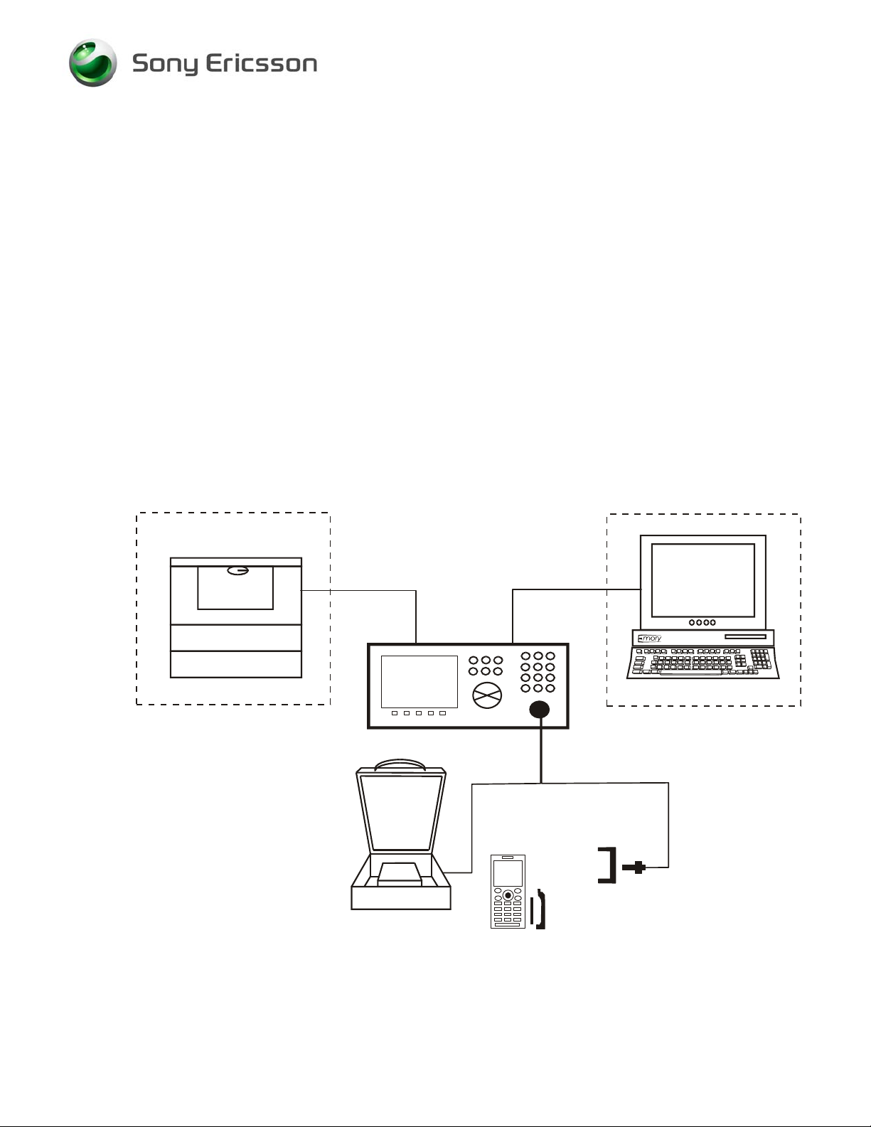
2.1 Test Set-Up Go/No Go test
All test hardware necessary for this test set up is documented in the Mechanical or
Electrical Equipment Lists.
PRINTER
OPTIONAL
Used for
Radiated Signal
to the Unit
TEST SET
RF CABLE
GPIB
CABLE
RF PROBE
HOLDER
RF PROBE
COMPUTER
OPTIONAL
Used for
Conducted Signal
*
to the Unit
The RF Probe Holder and the Battery Cover may not be used for every product.
1211-1559_ 1
See the Installation Instructions and Test Instructions for details.
*
© Sony Ericsson Mobile Communications AB
RF SHIELD
BOX
BATTERY AND
BATTERY COVER
*
2(14)
Page 3

Installation Instruction, Electrical
2.2 Test Set
2.2.1 W760
A Quad Band GSM 850/900/1800/1900 and WCDMA Test Set approved according to
the Electrical Equipment List must be used.
It should be installed according to the Instrument Manufacturer’s Instructions.
2.2.2 W760c
A Quad Band GSM 850/900/1800/1900 Test Set approved according to the Electrical
Equipment List must be used.
It should be installed according to the Instrument Manufacturer’s Instructions.
2.3 RF Connections Antenna Coupler
Connect the RF Cable between the RF-port of the Test set and the RF Shield box. The
Antenna Coupler should be installed into the RF Shield Box according to the
manufacturer’s instructions.
2.4 RF Connections Probe (optional)
Connect the RF-cable between the RF-port of the Test set and the RF Probe. Assemble
the RF Probe to the RF-holder according to the information in the Test Instruction
Electrical.
1211-1559_ 1
© Sony Ericsson Mobile Communications AB
3(14)
Page 4
Installation Instruction, Electrical
3 Calibration
NOTE! W760 requires both GSM and WCDMA Calibration.
W760c requires only GSM Calibration.
There are two types of calibration; GSM and WCDMA. Due to the sensitivity of the
phone from outside interference during WCDMA calibration, a Shield box and Service
Tool Test Interface are required for WCDMA Calibration. These can be also used for
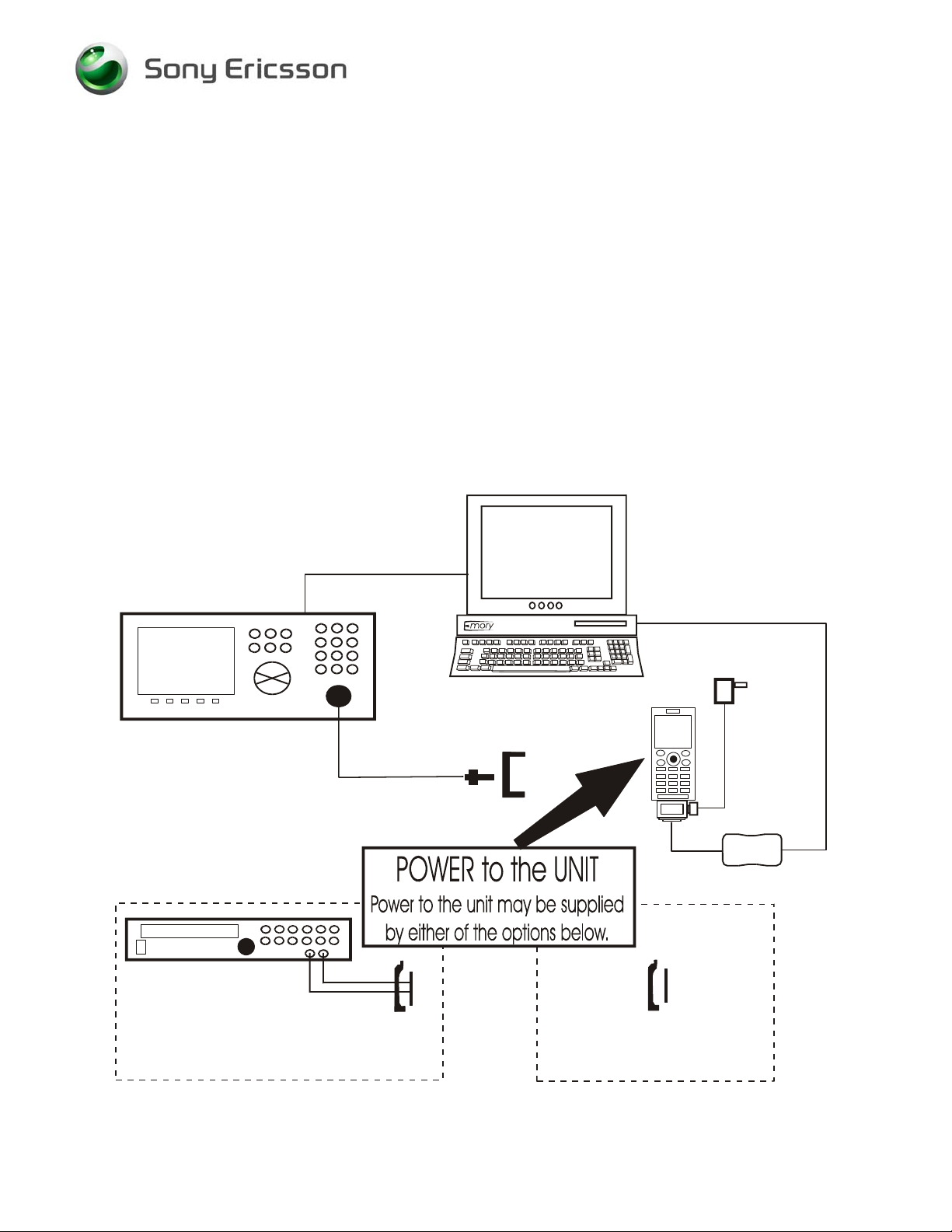
GSM Calibration. Section 3.1 depicts a GSM only setup. For GSM only, follow sections
3.2 thru 3.8. For WCDMA or GSM, follow sections 3.2 thru 3.6 and 3.9.
3.1 GSM Calibration Test set up – SERP (only authorized
centers)
COMPUTER
TEST SET
POWER SUPPLY
GPIB
CABLE
RF CABLE
RF PROBE
HOLDER
RF
PROBE
*
SEPI
CABLE
CHARGER
SEPI
USB
CABLE
DUMMY BATTERY
AND MODIFIED
BATTERY COVER
*
The RF Probe Holder, Battery Cover, and Modified Battery Cover may not be used for every product.
See the Installation Instructions and Test Instructions for details.
*
1211-1559_ 1
© Sony Ericsson Mobile Communications AB
FULLY CHARGED BATTERY
AND
BATTERY COVER
*
4(14)
Page 5

Installation Instruction, Electrical
3.2 Test Set
A Test Set approved according to the Electrical Equipment List must be used.
It should be installed according to the instrument Manufacturer’s Instructions.
3.3 GPIB card and cable
Use a GPIB card and cable according to the Electrical Equipment List. Use the GPIB
cable to connect the GPIB card in the computer to the test instrument.
3.4 Sony Ericsson programming interface – SEPI
The USB programming interface is delivered with the necessary software and instruction
for installation. The USB programming interface (SEPI) should be connected to a USBport on the computer.
3.5 USB Cable
The A-B Plug-Plug cable is the interface between the computer and the USB
programming interface (SEPI). Connect the cable between the USB programming
interface and the computer.
3.6 Phone Power during Calibration
There are two options for powering the phone during calibration, a fully charged Battery
or a Power supply with a Dummy Battery, both are acceptable.
3.6.1 Battery
A fully charged Sony Ericsson battery approved for this phone model must be used. The
part number can be found in the Mechanical Equipment List.
1211-1559_ 1
© Sony Ericsson Mobile Communications AB
5(14)
Page 6

Installation Instruction, Electrical
3.6.2 Power Supply
A Power Supply according to Electrical Equipment List must be used.
Set the output of the Power Supply as follows
• Voltage: 3.8Vdc
• Current: 2.0Amps
3.6.3 Dummy Battery
A Dummy Battery is to be used together with a power supply to power the phone.
Connect the cables from the Dummy Battery to the power supply, red cable to positive
output terminal and black cable to negative output terminal. There is a 3-position switch
on the Dummy Battery that should be set to position “B”.
3.7 RF Connection (GSM Calibration only)
Connect the RF-cable between the RF-port of the Test set and the RF Probe. Assemble
the RF Probe to the RF-holder according to the information in the Test Instruction
Electrical.
3.8 Sony Ericsson programming interface cable (GSM
Calibration only)
The cable is the interface between the USB programming interface (SEPI) and the
phone. A standard Sony Ericsson Mobile Communication charger must be connected to
the programming interface cable.
1211-1559_ 1
© Sony Ericsson Mobile Communications AB
6(14)
Page 7

Installation Instruction, Electrical
3.9 Calibration Shield box setup (WCDMA or GSM Calibration)
Due to the sensitivity of the phone from outside interference during WCDMA calibration,
a Shield box and Service Tool Test Interface are required for WCDMA Calibration.
These can be also used for GSM Calibration. A Wiltek 4921 Shield box and Service Tool
Test Interface can be found in the Electrical Equipment list. There are several options
available.
• The Wiltek 4921 Shield Enclosure box along with the Service Tool Test Interface.
• An existing Wiltek Shield box along with the Service Tool Test Interface and modified
rear cover can be used. Remove the coupler, replace the rear cover and follow the
instructions for the Wiltek 4921 Shield Enclosure box. The modified rear cover and N
terminator can be found in the Electrical Equipment list.
• Any Shield box with a RF Isolation factor of >50dbm, has a High density DB-15
connector and an RF-pass thru connection. Attach the Service Tool Test Interface to
the DB-15 connector.
1211-1559_ 1
© Sony Ericsson Mobile Communications AB
7(14)
Page 8

Installation Instruction, Electrical
The following pictures show how to setup a Wiltek 4921 Shield Enclosure box.
1
5
Picture 1
2
6
3
4
1. Connect the RF-cable between the RF-port of the Test set and the RF connector
on the modified Rear Panel.
2. Attach the Outside Service Tool Test Interface to the connector on the modified
Rear Panel.
3. Connect a standard Sony Ericsson Mobile Communication charger to the SEPI
Calibration interface.
4. Connect the Outside Service Tool Test Interface to the SEPI.
5. Attach the N terminator to the Coupler connection.
6. If a Power Supply is used instead of a standard fully charged battery, connect the
output of the Power Supply and the sense lines to the Outside Service Tool Test
Interface.
1211-1559_ 1
© Sony Ericsson Mobile Communications AB
8(14)
Page 9

Installation Instruction, Electrical
1
Picture 2
2
3
4
1. Attach the Inside Service Tool Test Interface to the modified Rear Panel.
2. Attach the RF Cable (Short) to the modified Rear Panel. The other end connects
to the Phone according to the information in the Test Instructions Electrical.
3. Connect the charging cable from the Inside Service Tool Test Interface to the
cable that attaches to the system connector on the phone.
4. If a Power Supply is used instead of a standard fully charged battery, connect the
power cables from the Inside Service Tool Test Interface to the Dummy Battery
black cable to black cable and red cable to red cable.
1211-1559_ 1
© Sony Ericsson Mobile Communications AB
9(14)
Page 10

Installation Instruction, Electrical
4 Software Loading
4.1 Set up
General Test set up to perform SW loading. All necessary hardware for this test set up is
documented in the Mechanical or Electrical Equipment list.
USB
ACTIVATION
DONGLE
DCU-65
CABLE
1211-1559_ 1
© Sony Ericsson Mobile Communications AB
10(14)
Page 11

Installation Instruction, Electrical
4.2 Computer
IBM compatible computer is required. The computer should include at least two USBports. Refer to Equipment List for minimum requirements.
4.3 USB Activation Dongle
A USB Activation Dongle is required for activation in Emma. The USB Activation Dongle
should be connected to a USB-port on the computer. Refer to the Emma Homepage
available from CSPN, for installation instructions.
4.4 Sony Ericsson programming cable – DCU-65
The cable is the interface between the computer and the phone. The DCU-65 cable
should be connected to a USB-port on the computer.
5 Software
5.1 Emma
Emma contains all software required to service the product. Installation and user
manuals are available in the Emma start page.
http://ma3.extranet.sonyericsson.com/ma3/
1211-1559_ 1
© Sony Ericsson Mobile Communications AB
11(14)
Page 12

Installation Instruction, Electrical
5.2 SERP Go/No Go Test Script
SERP stands for “Sony Ericsson Repair Platform”. It is an application used for testing,
calibrating and repairing Sony Ericsson mobile phones.
Download the latest revision of the SERP application from CSPN.
http://cspn.extranet.sonyericsson.com
This application is located in the dropdown menu
Repair Instructions-Electrical/SERP application
1. Unzip the file and open the file “Release Notes and Installation Guide” for installation
instructions.
2. After SERP is installed a file titled “SERPINFO.htm” will be placed on the Windows
Desktop. This file contains numerous documents including:
• SERP Users Manual – This document contains detailed operating and fault
reporting instructions.
• R&S Grid plate for SERP – This document contains an overview and ordering
information for the Rhode & Schwarz Grid Plate used with the Rhode & Schwarz
coupler. Also there is a list of supported SEMC handsets and mounting positions.
• SERP Release Notes and Installation Guide – This document contains system
requirements, release notes and an Installation Guide.
5.3 SERP Calibration (only authorized centers)
Download the latest revision of the SERP application from CSPN.
http://cspn.extranet.sonyericsson.com
This application can be found from the dropdown menu
Repair Instructions-Electrical/SERP application
1. Unzip the file and open the file “Release Notes and Installation Guide” for installation
instructions.
2. Follow the Installation instructions to install SERP.
1211-1559_ 1
© Sony Ericsson Mobile Communications AB
12(14)
Page 13

Installation Instruction, Electrical
5.4 Anritsu MT8510B Go/No-Go Test Script (Stand alone)
The Anritsu MT8510B (SEMC approved) script can be obtained from Anritsu at the
following Website, Registration is required.
https://www1.anritsu.co.jp/Download/MService/Login.asp
Follow the Instructions in the MT8510B Install Procedure for installation of the Test
Parameter files.
The Test Parameter files have attenuation values for the Anritsu MA8120E Shield box.
The Anritsu MA8120E shield box should be used with the Anritsu MT8510B Test
instrument.
6 Lead-Free Electrical Repair
This product is manufactured with lead-free solder and lead-free components. During
electrical repair, it is critical to make sure that no lead is introduced into the product. For
this reason, certain repair materials and equipment must be designated as lead-free and
labelled accordingly. A lead-free work area must be setup that is completely separated
from work areas that are used to make leaded repairs. The lead-free work area must
also be clearly labelled as shown in the figure below. Certain items must be designated
for lead-free work only. Some of the items that need to be clearly labelled in this way
are listed in the table below. Note that any item that contacts the solder must be labelled
and used for lead-free work only.
Soldering Tips Wicking Tape Tip Cleaner (steel wool)
Solder Tip Tinner Soldering Iron
1211-1559_ 1
© Sony Ericsson Mobile Communications AB
13(14)
Page 14

Installation Instruction, Electrical
Because of cost and space limitations, some repair centers may not be able to assign a
full bench to lead-free repairs. In this case, both lead-free and leaded repair setups can
share the same bench, but they must be clearly marked with signs and separated by a
physical divider. In the figure below, the large hot air device functions as the divider.
7 Revision History
Rev. Date Changes / Comments
1 2008-05-28 Initial Release
2 2008-07-16 Updated Stand alone GNG Section 5.4
1211-1559_ 1
© Sony Ericsson Mobile Communications AB
14(14)
 Loading...