

Page 1

Trouble Shooting Guide, Electrical
Trouble Shooting Guide, Electrical
Applicable for W710, Z710
Contents
1
General...............................................................................................................2
2 Repair Actions for Manual Test Failures......................................................... 3
2.1 Power On / Off.......................................................................................3
2.2 Software Flash ...................................................................................... 3
2.3 Charging................................................................................................3
2.4 Hands-Free connection (PHF) .............................................................. 4
2.5 SIM........................................................................................................4
2.6 Display...................................................................................................4
2.7 Keypad Illumination (LEDs)...................................................................4
2.8 Main Keypad Keys ................................................................................4
2.9 Volume Up / Down Key.........................................................................4
2.10 PTT Key ................................................................................................ 4
2.11 Flip Keys................................................................................................4
2.12 Keypad Lock Key .................................................................................. 4
2.13 Vibrator..................................................................................................4
2.14 Earphone (Receiver, Flip Speaker).......................................................4
2.15 Polyphonic Speaker (Alert, Ringer, Base Speaker) ..............................4
2.16 Microphone............................................................................................4
2.17 Real Time Clock....................................................................................4
2.18 Camera..................................................................................................4
2.19 Flip Sensor............................................................................................4
2.20 IR...........................................................................................................4
2.21 Bluetooth...............................................................................................4
2.22 FM Radio...............................................................................................4
2.23 Accelerometer.......................................................................................4
2.24 Memory Card.........................................................................................4
3 Repair Actions for Go/No Go Test Failures....................................................4
4 Repair Actions for Calibration Routine Failures ............................................5
4.1 GSM 850, 900, 1800, or 1900...............................................................5
4.2 EDGE 850, 900, 1800, or 1900.............................................................5
5 Revision History................................................................................................6
4/000 21-2/FEA 209 544/601 C
Company Internal
© Sony Ericsson Mobile Communi cat i ons AB
Page 2
Trouble Shooting Guide, Electrical
1 General
The purpose of this document is to indicate the electrical level repair actions associated with
the different failure symptoms.
For symptoms that have multiple repair actions, the repair actions are listed in order of their
probability of creating a successful repair. The first action has the highest probability, and
subsequent actions have lower probabilities. The intention is for the repair technician to
implement the first repair action and then retest the phone. If the phone continues to fail the
same test, then the technician should continue to the second repair action. If the phone
continues to fail the same test after all of the repair actions are exhausted, then the phone will
be considered not reparable at this level.
This document should be used only after the actions from the Mechanical Trouble Shooting
Guide have been exhausted for the specific symptom.
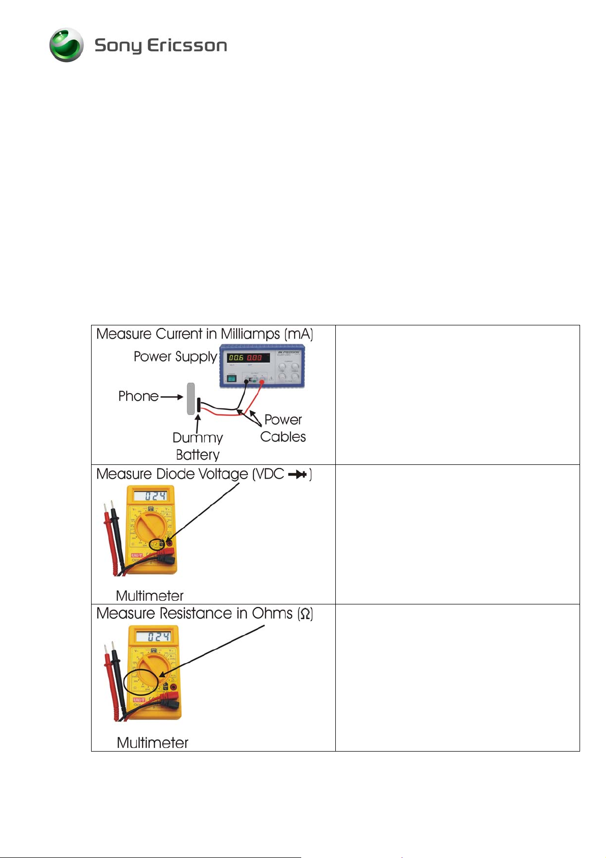
Voltage, current, and resistance information is provided for some symptoms to enable faster
repairs. The phone should be fully assembled. Purchasing this equipment and performing
these measurements is optional but recommended.
Perform current measurements using a
dummy battery and power supply with digital
current display. The phone should be fully
assembled.
Perform voltage measurements with a
multimeter.
Perform resistance measurements with a
multimeter.
4/000 21-2/FEA 209 544/601 C 2(6)
Company Internal
© Sony Ericsson Mobile Communi cat i ons AB
Page 3

Trouble Shooting Guide, Electrical
2 Repair Actions for Manual Test Failures
Failure Failure Symptom
2.1 Power On /
Off
2.2 Software
Flash
2.3 Charging
Current draw when powered off N1302
Current draw greater than 400
mAmps during power up sequence
Hangs at gray display with constant
vibration
Some current draw when pressing
power key, but current returns to 0
when power key is released
Measure resistance across L801:
(Ohms)
Resistance = 1.2 to 1.7 Ohms
Powers On when battery is installed
BUT will not power off
Powers On when power key is
pressed BUT will not power off.
Power key fails service menu keypad
test.
Measure voltage across V501 (Vdc)
Pos1 to neg2 = 0.54 – 0.56
Pos1 to neg3 = 0.49 – 0.52
Pos2 to neg3 = 0.56 – 0.58
Power on sequence begins (quick
vibration and display flash), then
display darkens. Maintains a small
current (less than 20 mAmps)
Other symptoms Replace X800 if damaged
EMMA does not respond.
Display turns on and charging icon
appears.
Measure voltage across V601 (Vdc)
Pos1 to neg2 = 0.66 – 0.69
Pos1 to neg3 = 0.66 – 0.68
Measure voltage across V604 (Vdc)
Pos1 to neg2 = 1.03 – 1.06
Pos1 to neg6 = 0.51 – 0.53
Pos3 to neg4 = 0.45 – 0.48
Charging from power outlet
Measure voltage across V803 (Vdc)
Pos1 to neg5 = 0.45 – 0.48
Pos4 to neg5 = 0.70 – 0.72
Measure voltage across V804 (Vdc)
Pos1 to neg4 = 2.78 – 2.81
Pos1 to neg5 = 0.40 – 0.43
Repair Action
N1300
N705
N1300
N705
B300
If resistance is outside of range,
then replace L801
If voltage is outside of range, then
replace V501
N1206
N1203
D601
If voltage is outside of range, then
replace V601
If voltage is outside of range, then
replace V604
If voltage is outside of range, then
replace V803
If voltage is outside of range, then
replace V804
4/000 21-2/FEA 209 544/601 C 3(6)
Company Internal
© Sony Ericsson Mobile Communi cat i ons AB
Page 4

Trouble Shooting Guide, Electrical
Failure
2.4 Hands-Free connection (PHF)
2.5 SIM
2.6 Display
2.7 Keypad
Illumination
(LEDs)
2.8 Main Keypad Keys
2.9 Volume Up / Down Key
2.10 PTT Key
2.11 Flip Keys
2.12 Keypad Lock Key
2.13 Vibrator
2.14 Earphone (Receiver, Flip Speaker)
2.15 Polyphonic Speaker (Alert, Ringer, Base Speaker)
2.16 Microphone
2.17 Real Time Clock
2.18 Camera
2.19 Flip Sensor
2.20 IR
2.21 Bluetooth
2.22 FM Radio
2.23 Accelerometer
2.24 Memory Card
Failure Symptom
Charging from computer via USB
Measure voltage across V609 (Vdc)
Pos1 to neg3 = 0.21 – 0.23
Navigation LEDs - Individual V562-V569
Number Key LEDs - Individual V555-V561, V701
LED Group V555-V561 V526
LED Group V562-V569 V537
Repair Action
If voltage is outside of range, then
replace V609
D601
N703
Replace X701 if damaged
Replace X424 if damaged
No Repair Action
Replace X1221 if damaged
Replace X1221 if damaged
Replace X424 if damaged
S527
Replace X424 if damaged
Replace X424 if damaged
Replace X1214, X1215 if
damaged
N704, N705
Replace X702 if damaged
B300
Replace X424 if damaged
N810
N401
N400
D600
N1100
N807
No Repair Action
N501
X201
3 Repair Actions for Go/No Go Test Failures
Failure Repair Action
Fails any part of Go/No Go testing
Fails Go/No Go test, but passes
calibration
Fails Go/No Go test after passing
calibration
4/000 21-2/FEA 209 544/601 C 4(6)
Company Internal
© Sony Ericsson Mobile Communi cat i ons AB
run the calibration routine
replace the antenna
check X1202 and X1204 for damage and replace if
necessary
rerun the phone through Go/No Go testing
change X1201 and retest
Page 5

Trouble Shooting Guide, Electrical
4 Repair Actions for Calibration Routine Failures
4.1 GSM 850, 900, 1800, or 1900
The variable F in the table below will be replaced by one of the different frequencies
(GSM850, GSM900, etc.).
Routine Repair Action
F_Calibrate_RXVCO
N1203
F_Calibrate_TXVCO
F_Calibrate_TXCHVCO
F_Check_Output_Power N1300
F_Calculate_POWTX_Value N1300
Calibrate_VCXO N1206
F_Measure_Multiframe N1300
F_RSSI_Calibration N1203
4.2 EDGE 850, 900, 1800, or 1900
The variable F in the table below will be replaced by one of the different frequencies
(EDGE850, EDGE900, etc.).
The variable X in the table below will be replaced by one of the different levels (1, 2, or
3).
N1203
N1203
X1201
N1204
N1204
N1204
Routine Repair Action
F_Check_Output_Power N1300
F_Get_POWTX_Value_For_PLX N1300
F_Calibrate_VGAGAINX
F_Calibrate_PowerX
4/000 21-2/FEA 209 544/601 C 5(6)
Company Internal
© Sony Ericsson Mobile Communi cat i ons AB
N1300
N1203
N1300
N1203
Page 6

Trouble Shooting Guide, Electrical
5 Revision History
Rev. Date Changes / Comments
A 2006-Aug-29 Initial Release
B 2006-Nov-27 Removed N811 and X903 from FM radio section. These parts are not
reparable. Attempting to remove the shield can causes solder ball shorts
under the FM radio ASIC.
C 2007-Aug-15 Added N1100 to Bluetooth section.
Added N705 to Power section.
4/000 21-2/FEA 209 544/601 C 6(6)
Company Internal
© Sony Ericsson Mobile Communi cat i ons AB
 Loading...