

Sony-Ericsson W700 Service Manual WORKING INSTRUCTION

D750i, K758c, W800 and W700 Working Instructions -
Mechanical
Working Instructions - Mechanical
Applicable for D750i, K758c, W800 and W700
Contents
1 Read this first!..............................................................................................3
2 Introduction..................................................................................................4
3 Repair actions..............................................................................................5
3.1 Battery Cover & Battery.................................................................................6
Battery Cover & Battery continued...................................................................... 7
3.2 Antenna Cover ..............................................................................................8
Antenna Cover continued .................................................................................... 8
Antenna Cover continued .................................................................................... 9
3.3 Front............................................................................................................10
Front continued .................................................................................................11
Front continued .................................................................................................12
3.4 Keyboard.....................................................................................................13
3.5 Plastic Carrier.............................................................................................. 14
Plastic Carrier continued...................................................................................15
3.6 LCD ............................................................................................................17
LCD continued...................................................................................................18
3.7 PBA ............................................................................................................19
PBA continued...................................................................................................20
PBA continued...................................................................................................21
3.8 Camera........................................................................................................22
3.9 Antenna.......................................................................................................23
3.10 Camera Flex.............................................................................................. 24
3.11 Speaker Box..............................................................................................25
3.12 System Connector..................................................................................... 26
3.13 Vibrator...................................................................................................... 27
3.14 Bluetooth Antenna..................................................................................... 28
3.15 IrDA Window .............................................................................................28
3.16 On/Off Key.................................................................................................29
3.17 Volume Key............................................................................................... 29
3.18 Music Player Key.......................................................................................30
3.19 Camera Key ..............................................................................................30
3.20 Frame........................................................................................................31
3.21 Camera Gasket.........................................................................................31
3.22 Tape, MS Duo...........................................................................................32
3.23 Support Pad, LCD.....................................................................................32
3.24 Camera Flex Pad, upper...........................................................................33
3.25 Camera Flex Pad (upper) & Camera BTB tape.........................................34
Camera Flex Pad (upper) & Camera BTB tape continued................................35
3.26 Joystick Button..........................................................................................36
3.27 Keyboard Foil............................................................................................37
3.28 Ground Springs.........................................................................................38
3.29 Spacer, board-to-board connector ............................................................39
3.30 Tape, plastic carrier.................................................................................. 39
3.31 Liquid Intrusion Indicator...........................................................................40
3/00021-1/FEA 209 544/95 G
Company Internal
©
Sony Ericsson Mobile Communications AB

D750i, K758c, W800 and W700 Working Instructions - M e chanical
3.32 Memory Card Rubber Lid.......................................................................... 41
3.33 Plug, external antenna ..............................................................................41
4 Label ...........................................................................................................42
5 Revision History ........................................................................................43
3/00021-1/FEA 209 544/95 G
Company Internal
©
Sony Ericsson Mobile Communications AB
2(43)
D750i, K758c, W800 and W700 Working Instructions - M e chanical
1 Read this first!
After reading section 2 ‘Introduction’ and the first page of section 3 ‘Repair Actions’,
do as follows when a mechanical part needs to be replaced:
• Search for the part name on the contents page and go to the page number
where the instruction is found
• Disassemble the phone as far as needed by moving to the instructions stated as
e.g. Follow the Removal instructions of sections 3.1 – 3.6
• Carry out the actual repair action as described
• Assemble the phone by moving to the instructions stated as
e.g. Follow the Assembly instructions of sections 3.6 – 3.1 (pls. note the reverse order)
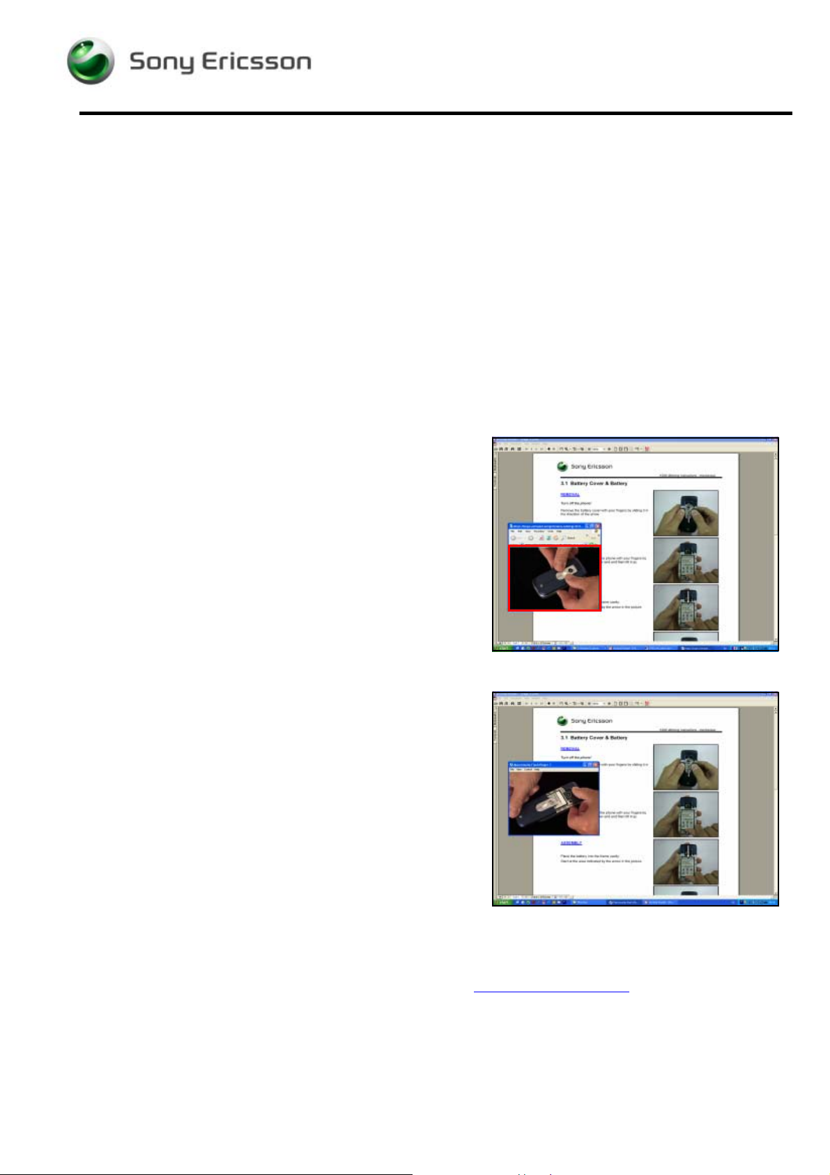
When watching the document off-line (after downloading
and extract the ZIP-file), most of the Removal and
Assembly headings are blue-coloured and underlined:.
By clicking on such a heading, a Flash Player window
opens, showing a video clip of the actual
removal/assembly.
The flash movie can be controlled from the keyboard by
holding down the Ctrl-key and pressing another key as
follows:
- Start and Stop: Ctrl – Enter
- Rewind to start position: Ctrl – R
- Move one small step forward: Ctrl – right arrow
- Move one small step back: Ctrl – left arrow
If your computer is set up to show Flash movies in an
Internet Explorer window, the movies will most likely be full
size, resulting in poor picture quality.
To shrink the video window to its proper size, drag the
bottom right corner of the Internet Explorer window until
the movie is shown without blurs and edges, which occurs
when the movie window is approx. 12 x 9 cm (indicated by
the red frame in the adjacent picture).
However, it is recommended to have your computer set up
to have the Flash movies played by the Flash Player
application.
NOTE: Flash Player ver. 6 or later must be installed on the computer.
The Flash Player can be downloaded free of charge from www.macromedia.com
3/00021-1/FEA 209 544/95 G
Company Internal
©
Sony Ericsson Mobile Communications AB
.
3(43)
D750i, K758c, W800 and W700 Working Instructions - M e chanical
2 Introduction
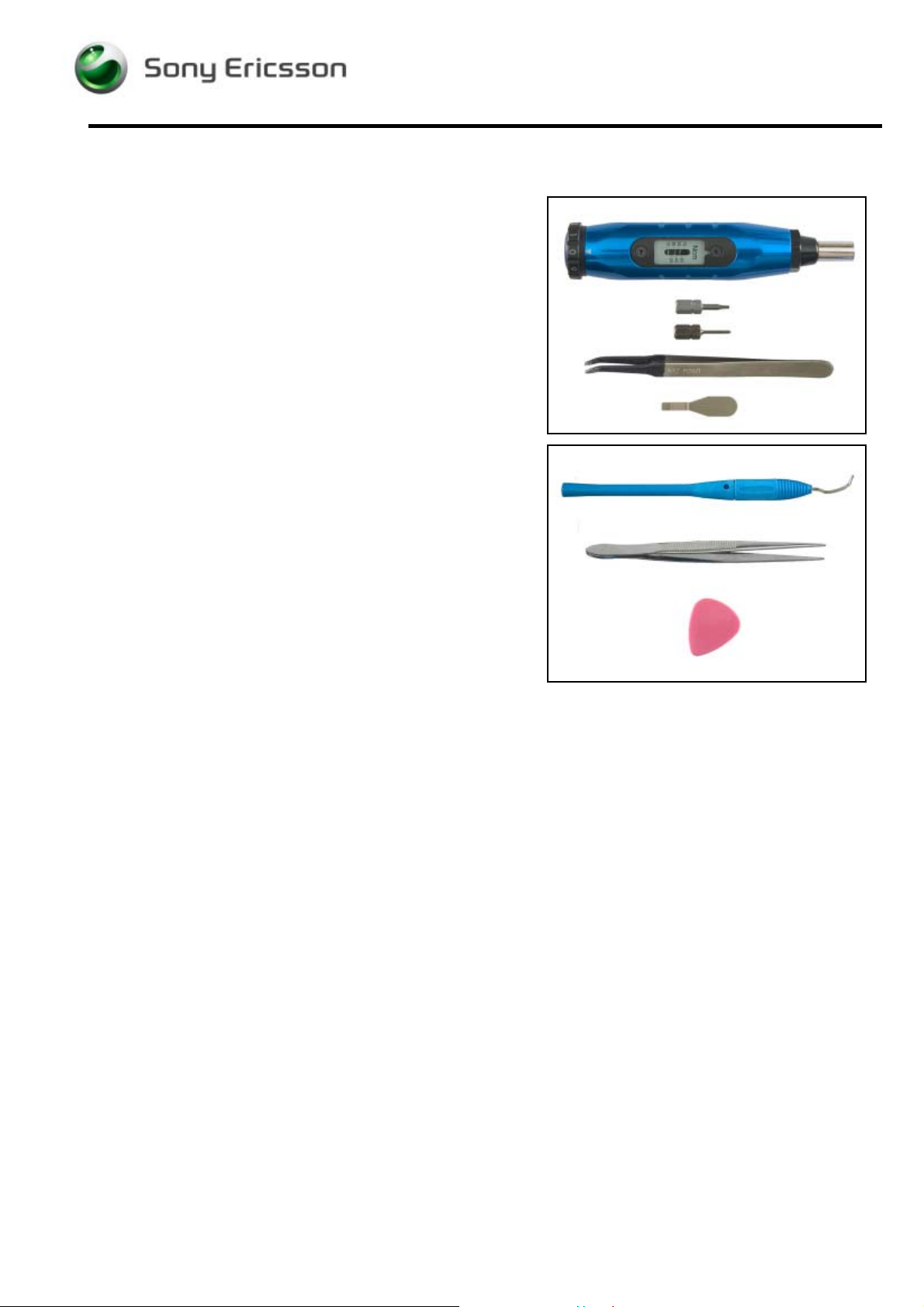
Special Tools
No new special tools are introduced but a few other
Sony Ericsson tools are required:
• NTZ 112 459 Torque screwdriver (or equivalent)
• NTZ 112 288 Torx bit no. 6
• NTZ 112 1052 Phillips bit
• NTZ 112 521 Flexfilm assembly tool
• NTZ 112 302/2 Front opening tool
Standard Tools
The following tools have to be locally purchased:
• Dentist hook
• Blunt pair of tweezers
• Guitar pick
ESD Equipment
Protect the phone from ESD damages whenever it has been opened by using:
• ESD-gloves (cotton gloves)
• ESD-wristband
Adhesives
Use a dentist hook or a blunt pair of tweezers to remove old adhesives.
If necessary, clean the surface with isopropyl alcohol before attaching new adhesives.
Caution
Keep all contact surfaces clean of dirt and hand grease.
3/00021-1/FEA 209 544/95 G
Company Internal
©
Sony Ericsson Mobile Communications AB
4(43)
D750i, K758c, W800 and W700 Working Instructions - M e chanical
3 Repair actions
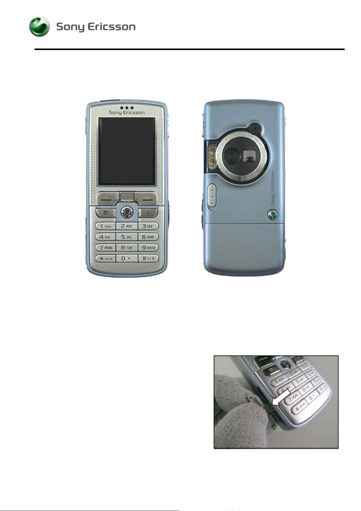
FRONT & REAR VIEWS
PRECAUTIONARY ACTIONS
Turn off the phone!
Check that there is no memory stick inside the phone!
Can be removed without gloves.
3/00021-1/FEA 209 544/95 G
Company Internal
©
Sony Ericsson Mobile Communications AB
5(43)
D750i, K758c, W800 and W700 Working Instructions - M e chanical
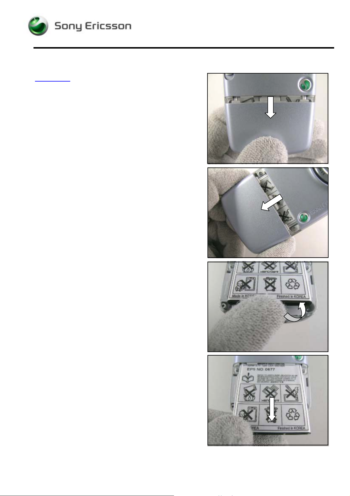
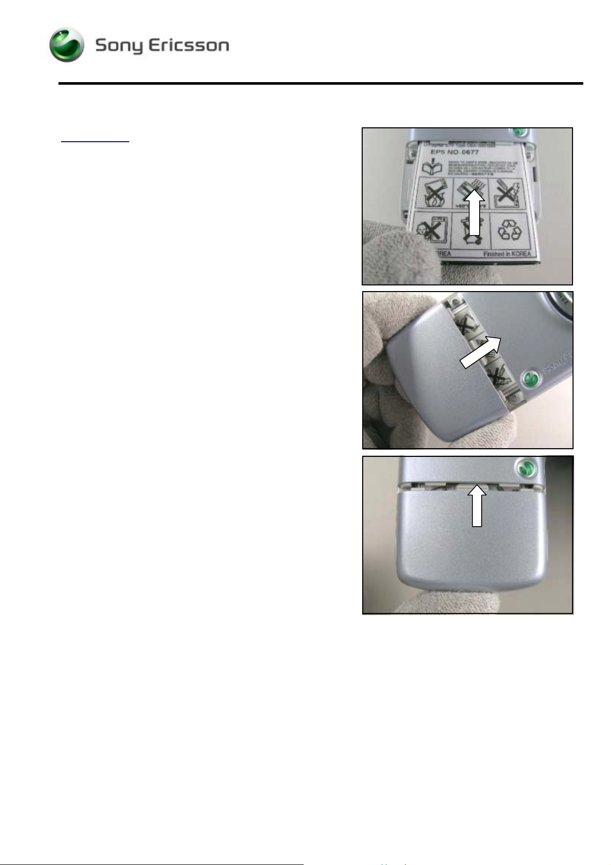
3.1 Battery Cover & Battery
REMOVAL
Remove the battery cover with your hand.
Force the battery cover to slide from its locked position
towards the end of the phone.
Slide down the battery cover completely and remove it.
Remove the battery from the phone with your fingers.
Lift the battery up to release it.
If not released, turning the phone around at the same
time will make it become released!
Remove the battery from the phone with your fingers.
3/00021-1/FEA 209 544/95 G
Company Internal
©
Sony Ericsson Mobile Communications AB
6(43)
D750i, K758c, W800 and W700 Working Instructions - M e chanical
Battery Cover & Battery continued
ASSEMBLY
Slide the battery into the frame cavity with your fingers
until it is secured in its proper position.
Start at the bottom and slide the battery cover onto the
phone.
Push with your thumb on the battery cover until it is
completely closed.
3/00021-1/FEA 209 544/95 G
Company Internal
©
Sony Ericsson Mobile Communications AB
7(43)
D750i, K758c, W800 and W700 Working Instructions - M e chanical
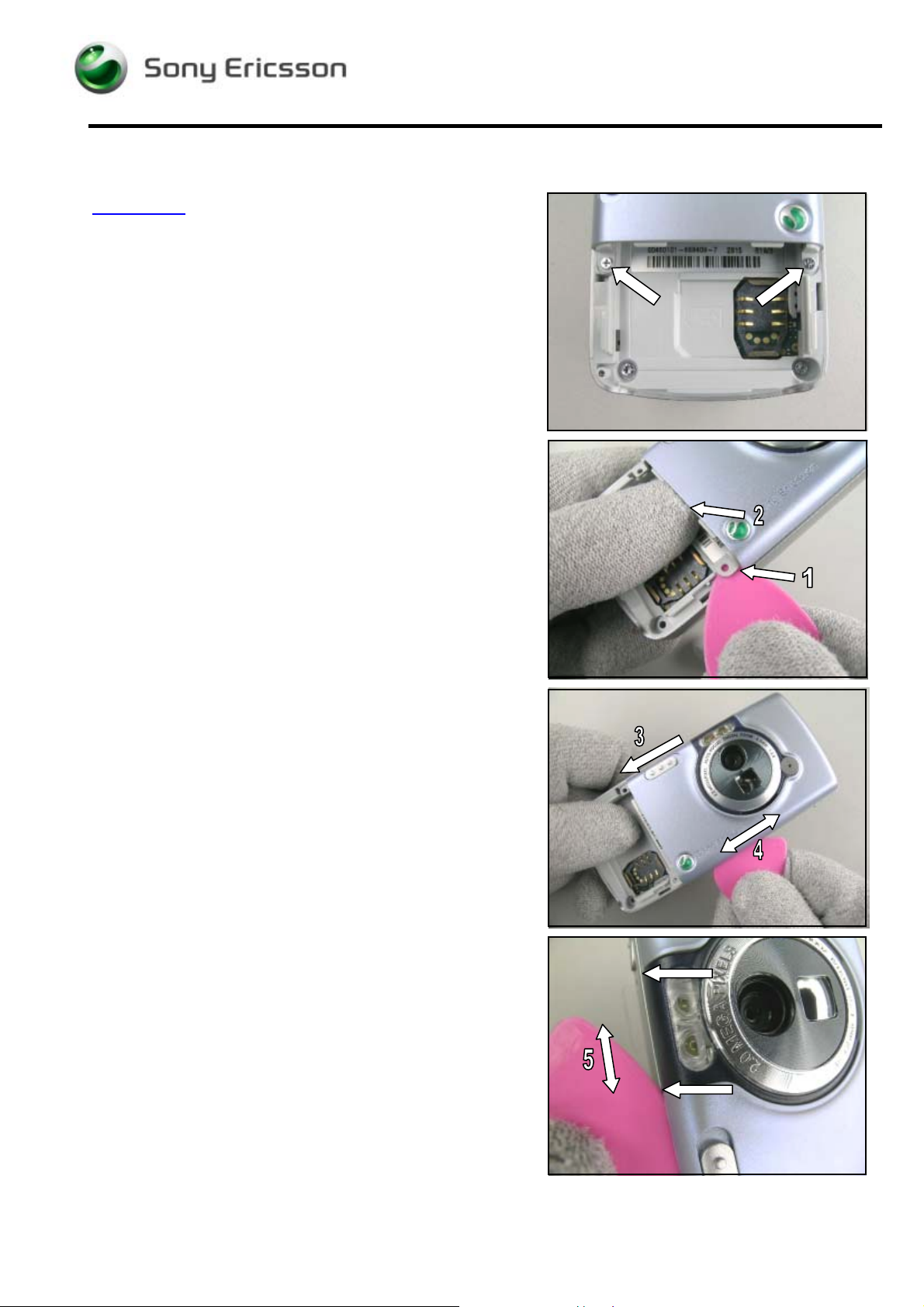
3.2 Antenna Cover
REMOVAL
Follow the Removal instructions of section 3.1
Remove the two screws by using bit NTZ 112 1052
(Phillips bit).
Removed screws cannot be reused and must be
scrapped!
Be careful not to scratch the antenna cover and the
frame with the guitar pick!
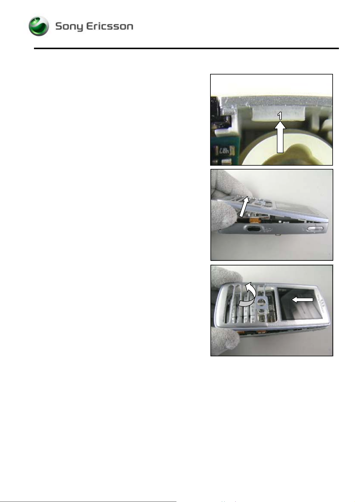
The camera lid has to be opened before the antenna
cover is removed from the frame (3, picture below)!
Open the phone with the guitar pick by starting at pos. 1.
It will be easier to insert the guitar pick between the
antenna cover and the frame if you at the same time bend
the cover slightly upwards with your thumb (2).
Gently move the guitar pick along the gap both ways (4)
until the antenna cover is loose on all sides.
Be careful not to scratch/damage the antenna cover with
the guitar pick where the two different plastics meet
(indicated by arrows)!
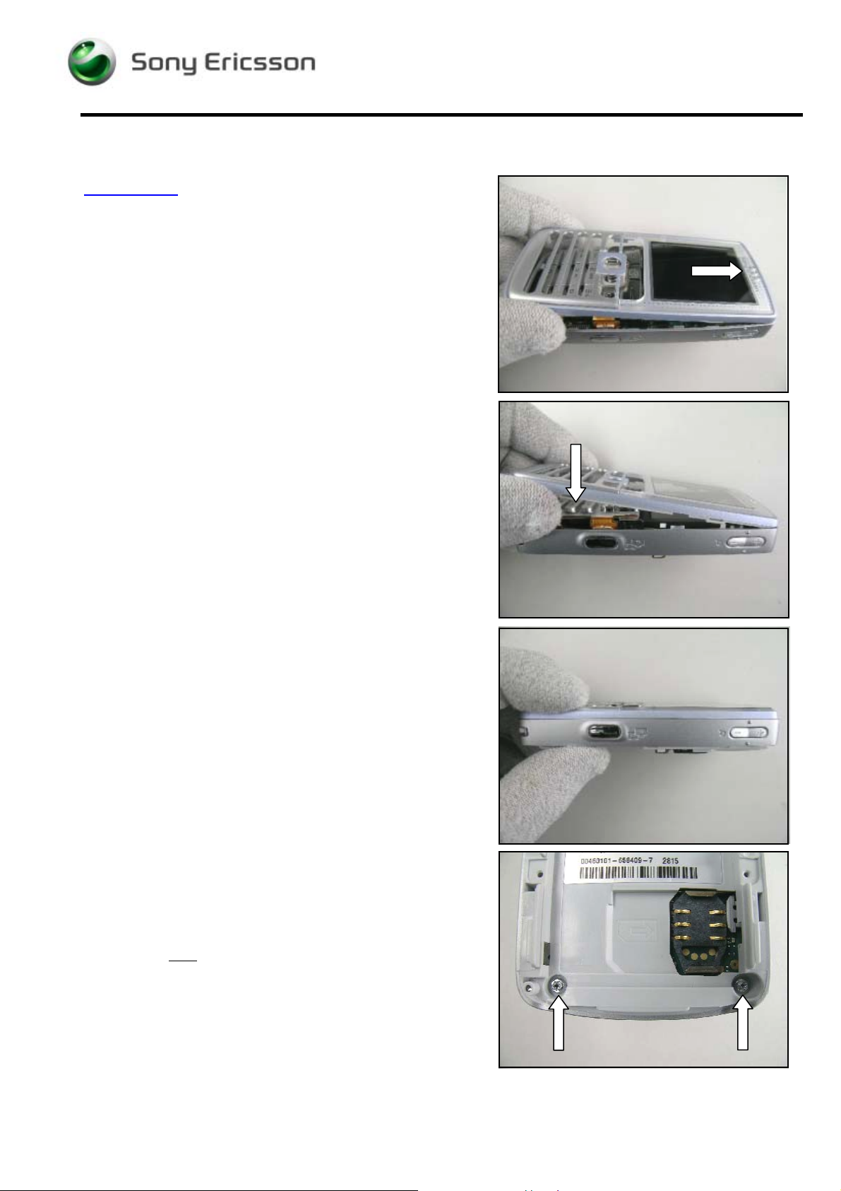
If necessary, open up with the guitar pick on the opposite
side (5).
3/00021-1/FEA 209 544/95 G
Company Internal
©
Sony Ericsson Mobile Communications AB
8(43)
D750i, K758c, W800 and W700 Working Instructions - M e chanical
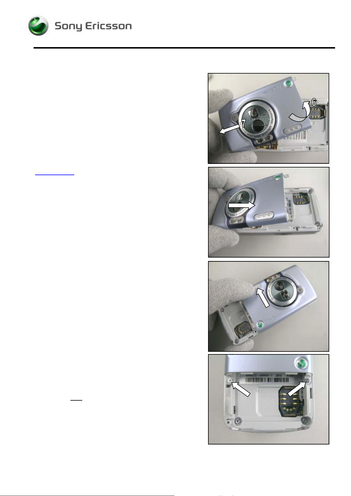
Antenna Cover continued
Be careful not to damage the antenna cover and the
frame as they become separated!
Gently lift the cover in the loose end (6) and then
slide/wiggle it forward in the arrow direction (7) until it can
be removed.
ASSEMBLY
The camera lid has to be open when the antenna cover is
assembled to the frame!
Place the antenna cover over the frame starting at the top
and then snap them together.
Check that the antenna cover is properly assembled,
i.e. no gaps along the sides!
If there still is a gap somewhere, gently press the two
halfs together with your fingers!
Close the camera lid.
±
Apply 9 Ncm (
the bit NTZ 112 1052 (Phillips bit)!
2 Ncm) torque for the screws by using
Tighten two new
screws through the antenna cover into
the frame.
Follow the Assembly instructions of section 3.1
3/00021-1/FEA 209 544/95 G
Company Internal
©
Sony Ericsson Mobile Communications AB
9(43)
D750i, K758c, W800 and W700 Working Instructions - M e chanical
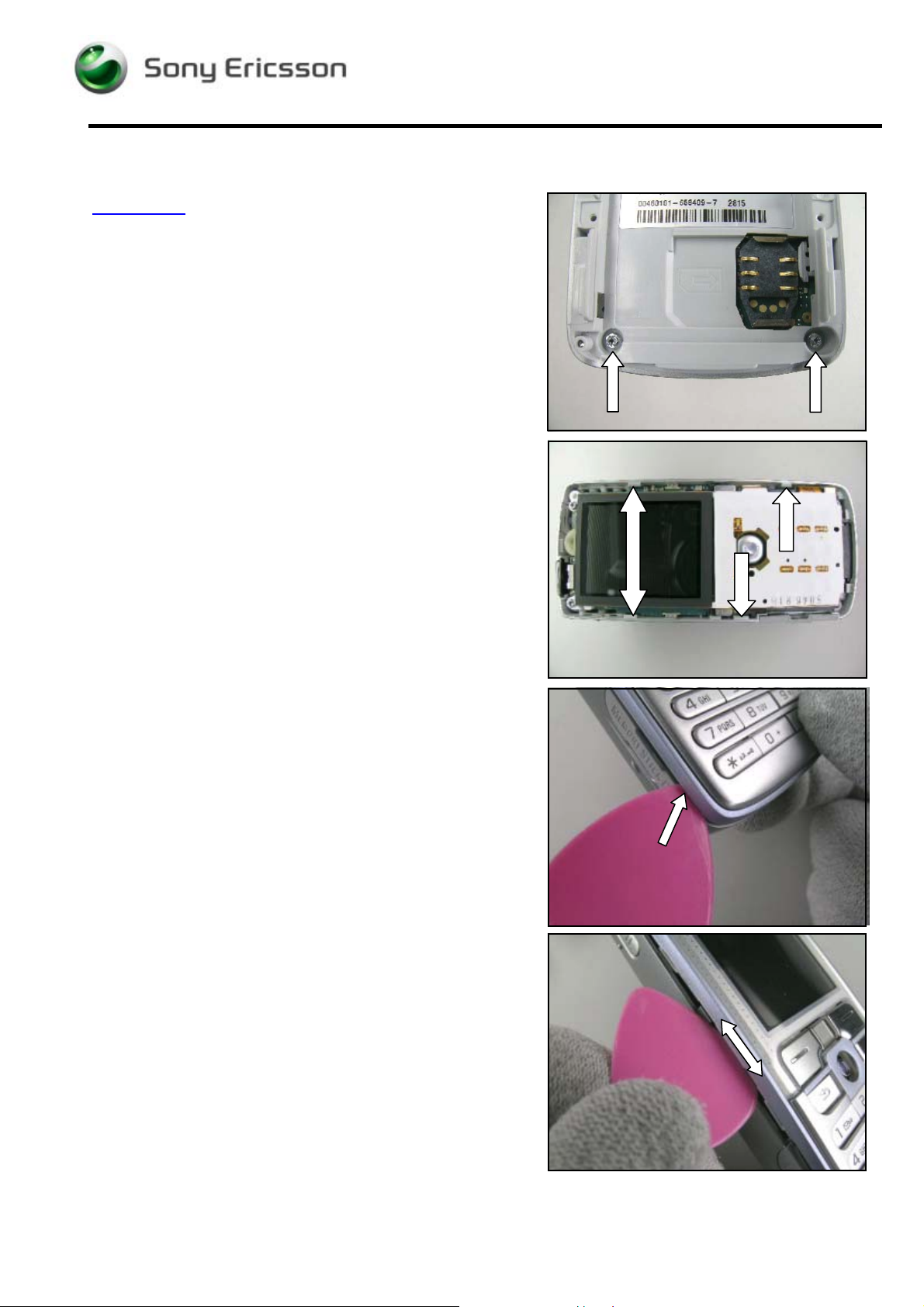
3.3 Front
REMOVAL
Follow the Removal instructions of section 3.1 – 3.2
Remove the two screws at the bottom of the phone by
using NTZ 112 288 (torx bit no. 6).
Removed screws cannot be reused and must be
scrapped!
Be most careful when sliding the guitar pick where the
frame hooks secure the front!
Be careful not to scratch the phone with the guitar pick!
Open the phone with the guitar pick, starting at the
memory card rubber lid.
Then gently move the guitar pick along the gap both ways
until the front is loose on all sides.
If necessary do the same thing on the opposite side.
3/00021-1/FEA 209 544/95 G
Company Internal
©
Sony Ericsson Mobile Communications AB
10(43)
D750i, K758c, W800 and W700 Working Instructions - M e chanical
Front continued
When separating the front from the frame you have to be
most careful not to damage these parts and in particular
avoid damage to the front caused by the top hook (1) of
the frame!
Do not bend the front to much apart from the frame to
avoid damages to the front caused by the top hook!
Sometimes the keyboard will fall out when the front is
removed.
Be careful not to damage the front and the frame as they
become separated!
Sometimes it demands quite a lot of force to remove the
front!
Wiggle the front gently side to side while pulling the front
away from the frame.
3/00021-1/FEA 209 544/95 G
Company Internal
©
Sony Ericsson Mobile Communications AB
11(43)
D750i, K758c, W800 and W700 Working Instructions - M e chanical
Front continued
ASSEMBLY
Remove the inside protection (new front only)!
Do not to scratch the glass with the tweezers!
Use air blow equipment to clean the front glass
Make sure the keyboard is in its proper position!
Place the front at the top over the frame.
Press the front forward until it snaps onto the top hook.
Then fold down the front against the frame and start to
snap them together.
Gently press with your fingers around the front.
Make sure that there are no gaps around the phone!
If there still is a gap somewhere, gently press the two
halfs together with your fingers!
Apply 18 Ncm torque for the screws using
NTZ 112 288 (torx bit no.6)!
Tighten two new
screws in the frame cavities.
Follow the Assembly instructions of section 3.2 – 3.1
3/00021-1/FEA 209 544/95 G
Company Internal
©
Sony Ericsson Mobile Communications AB
12(43)
D750i, K758c, W800 and W700 Working Instructions - M e chanical
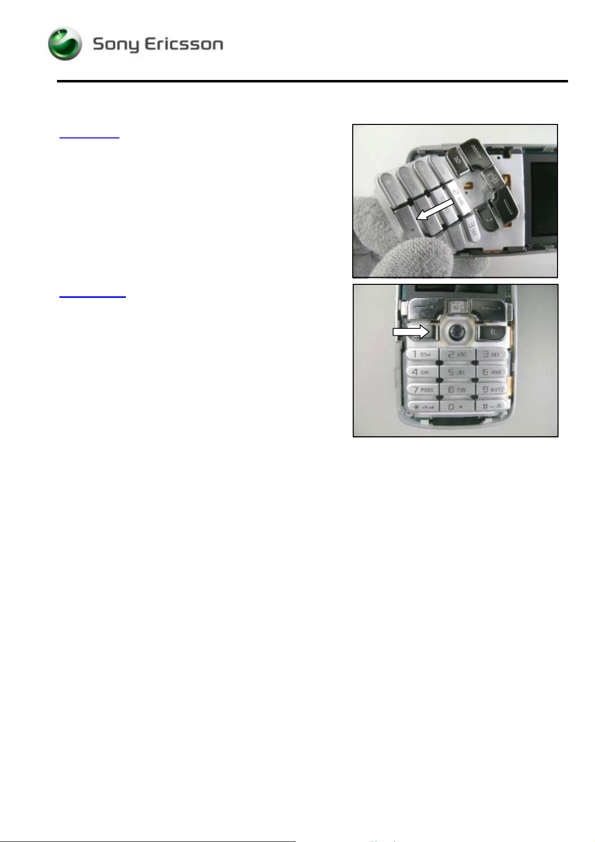
3.4 Keyboard
REMOVAL
Follow the Removal instructions of section 3.1 – 3.3
Remove the keyboard by hand or tweezers.
ASSEMBLY
Make sure the keyboard is placed in its proper position
by using the guide peg on the keyboard and the guide
hole on the keyfoil!
Place the keyboard onto the keyfoil.
Follow the Assembly instructions of section 3.3 – 3.1
3/00021-1/FEA 209 544/95 G
Company Internal
©
Sony Ericsson Mobile Communications AB
13(43)
 Loading...