

Page 1

Trouble Shooting Guide, Electrical
Trouble Shooting Guide, Electrical
Applicable for W300c, W300i
Contents
General.............................................................................................................................2
1
2
Repair Actions for Manual Test Failures.....................................................................3
2.1
Power On / Off ..................................................................................................3
2.2
Software Flash...................................................................................................3
2.3
Charging............................................................................................................3
2.4
Hands-Free connection (PHF)...........................................................................3
2.5
SIM....................................................................................................................3
2.6
Charging indicator (RED LED).........................................................................3
2.7
Display...............................................................................................................3
2.8
Display Illumination..........................................................................................3
2.9
External Display Illumination ...........................................................................3
2.10
Keypad LEDs ....................................................................................................3
2.11
Keypad Keys .....................................................................................................3
2.12
Volume Up Key.................................................................................................3
2.13
Volume Down Key............................................................................................3
2.14
Music Key .........................................................................................................3
2.15
Vibrator .............................................................................................................3
2.16
Earphone (Receiver, Flip Speaker)....................................................................4
2.17
Polyphonic Speaker (Loudspeaker, Base Speaker)...........................................4
2.18
Microphone .......................................................................................................4
2.19
Real Time Clock................................................................................................4
2.20
Camera...............................................................................................................4
2.21
Flip Sensor.........................................................................................................4
2.22
IR.......................................................................................................................4
2.23
Bluetooth...........................................................................................................4
2.24
Memory Card Reader........................................................................................4
2.25
FM Radio...........................................................................................................4
3
Repair Actions for Go/No Go Test Failures .................................................................4
4
Repair Actions for Calibration Routine Failures.........................................................5
4.1
GSM 850, 900, 1800, or 1900...........................................................................5
4.2
EDGE 850, 900, 1800, or 1900.........................................................................5
5
Revision History..............................................................................................................6
4/000 21-2/FEA 209 544/600 A
©
Sony Ericsson Mobile Communications AB
Page 2
Trouble Shooting Guide, Electrical
1 General
The purpose of this document is to indicate the electrical level repair actions associated with the different
failure symptoms.
For symptoms that have multiple repair actions, the repair actions are listed in order of their probability of
creating a successful repair. The first action has the highest probability, and subsequent actions have lower
probabilities. The intention is for the repair technician to implement the first repair action and then retest the
phone. If the phone continues to fail the same test, then the technician should continue to the second repair
action. If the phone continues to fail the same test after all of the repair actions are exhausted, then the
phone will be considered not reparable at this level.
This document should be used only after the actions from the Mechanical Trouble Shooting Guide have
been exhausted for the specific symptom.
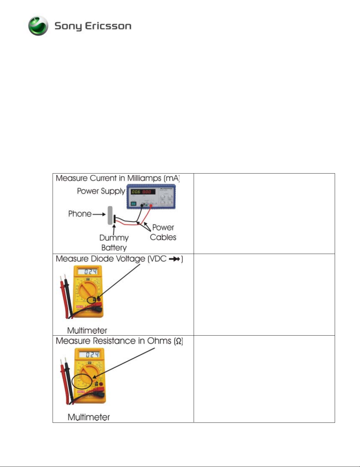
Voltage, current, and resistance information is provided for some symptoms to enable faster repairs.
Purchasing this equipment and performing these measurements is optional but recommended.
Perform current measurements using a dummy
battery and power supply with digital current
display. The phone should be fully assembled.
Perform voltage measurements with a multimeter.
Perform resistance measurements with a
multimeter.
4/000 21-2/FEA 209 544/600 A
©
Sony Ericsson Mobile Communications AB
2(6)
Page 3

Trouble Shooting Guide, Electrical
2 Repair Actions for Manual Test Failures
Failure Failure Symptom
2.1 Power On / Off
2.2 Software Flash
2.3 Charging
2.4 Hands-Free connection (PHF)
2.5 SIM
2.6 Charging indicator (RED LED)
2.7 Display
2.8 Display Illumination
2.9 External
Display
Illumination
2.10 Keypad LEDs
2.11 Keypad Keys
2.12 Volume Up Key
2.13 Volume Down Key
2.14 Music Key
2.15 Vibrator
Current draw when powered off
Current draw greater than 300 mAmps
Will not power on AND will not flash
Draws less than 50 mA, hangs at gray
display, and will not flash • B300
Some current draw when pressing power
key, but current returns to 0 when power
key is released
Powers On BUT will not power off
Other symptoms
EMMA gives “unrecognized device”
error and phone powers on
EMMA gives no response at all and
phone powers on
USB network connection icon flashes,
but USB progress icon does not appear
Charging from power outlet
Charging from computer via USB
Measure V808 from pin 1 to pin 3 with
positive lead on pin 1
VDC should equal 0.20 to 0.23.
Display is on, but dark
Display light comes on when battery is
installed
Keys dark. Both displays work
normally.
LEDs come on when battery is installed.
Individual LEDs are dark
Measure V702 from pin 1 to pin 3 with
positive lead on pin 1
VDC should equal 0.43 to 0.47.
Repair Action
• N1301
• N1300
• N1300
• N1201
• N1203
• L800
• V800
• V500
• Replace X800 if damaged
• N602, V604
• N801
• B300
• V803, V804
• If VDC is outside of range, then
replace V808
• N801
• N700
• Replace X701 if damaged
• V700
• No Repair Action
• N802
• V501
• V501
• V540
• V540
• Individual LEDs V511 – V520
• Z400
• S526
• Z400
• S524
• Z400
• S525
• If VDC is outside of range, then
replace V702
4/000 21-2/FEA 209 544/600 A
©
Sony Ericsson Mobile Communications AB
3(6)
Page 4

Trouble Shooting Guide, Electrical
Failure Failure Symptom
2.16 Earphone (Receiver, Flip Speaker)
2.17 Polyphonic Speaker (Loudspeaker, Base Speaker)
2.18 Microphone
2.19 Real Time Clock
2.20 Camera
2.21 Flip Sensor
2.22 IR
2.23 Bluetooth
2.24 Memory Card Reader
2.25 FM Radio
Repair Action
• No Repair Action
• Replace X703, X704 if damaged
• N703
• N701
• X705
• B300
• No Repair Action
• N400
• D201
• No Repair Action
• Replace X301 if damaged
• N805
• N803
• N1100
3 Repair Actions for Go/No Go Test Failures
Failure Repair Action
Fails any part of Go/No Go testing
Fails Go/No Go test, but passes calibration
Fails Go/No Go test after passing calibration
• run the calibration routine
• replace the antenna
• check X1201 for damage and replace if
necessary
• rerun the phone through Go/No Go testing
• change X1200 and retest
4/000 21-2/FEA 209 544/600 A
©
Sony Ericsson Mobile Communications AB
4(6)
Page 5

Trouble Shooting Guide, Electrical
4 Repair Actions for Calibration Routine Failures
4.1 GSM 850, 900, 1800, or 1900
The variable F in the table below will be replaced by one of the different frequencies (GSM850,
GSM900, etc.).
Routine Repair Action
F_Calibrate_RXVCO
• N1203
F_Calibrate_TXVCO
F_Calibrate_TXCHVCO
F_Check_Output_Power
F_Calculate_POWTX_Value
Calibrate_VCXO
F_Measure_Multiframe
F_RSSI_Calibration
4.2 EDGE 850, 900, 1800, or 1900
The variable F in the table below will be replaced by one of the different frequencies (EDGE850,
EDGE900, etc.).
• N1203
• N1203
• N1300
• X1200
• N1204
• N1300
• N1201
• N1300
• N1204
• N1203
• N1204
The variable X in the table below will be replaced by one of the different levels (1, 2, or 3).
Routine Repair Action
F_Check_Output_Power
F_Get_POWTX_Value_For_PLX
F_Calibrate_VGAGAINX
F_Calibrate_PowerX
4/000 21-2/FEA 209 544/600 A
©
Sony Ericsson Mobile Communications AB
• N1300
• N1300
• N1300
• N1203
• N1300
• N1203
5(6)
Page 6

Trouble Shooting Guide, Electrical
5 Revision History
Rev. Date Changes / Comments
A 2006-Apr-18 Initial Release
4/000 21-2/FEA 209 544/600 A
©
Sony Ericsson Mobile Communications AB
6(6)
 Loading...