

Page 1
PROTOCOL MANUAL
For General Release
MODEL
..............
VPL-PX20
VPL-PX30
VPL-VW10HT
DEST.
..........
WORLD
WORLD
WORLD
VERSION 1.0
Projector Firmware ARC32
VPL-PX20/PX30
LCD DATA PROJECTOR
VPL-VW10HT
LCD VIDEO PROJECTOR
LCD DATA/VIDEO PROJECTOR
Page 2

! WARNING
This manual is intended for qualified service personnel only.
To reduce the risk of electric shock, fire or injury, do not perform any servicing other than that
contained in the operating instructions unless you are qualified to do so. Refer all servicing to
qualified service personnel.
! W ARNUNG
Die Anleitung ist nur für qualifiziertes Fachpersonal bestimmt.
Alle Wartungsarbeiten dürfen nur von qualifiziertem Fachpersonal ausgeführt werden. Um die
Gefahr eines elektrischen Schlages, Feuergefahr und Verletzungen zu vermeiden, sind bei
Wartungsarbeiten strikt die Angaben in der Anleitung zu befolgen. Andere als die angegeben
Wartungsarbeiten dürfen nur von Personen ausgeführt werden, die eine spezielle Befähigung
dazu besitzen.
! AVERTISSEMENT
Ce manual est destiné uniquement aux personnes compétentes en charge de l’entretien. Afin
de réduire les risques de décharge électrique, d’incendie ou de blessure n’effectuer que les
réparations indiquées dans le mode d’emploi à moins d’être qualifié pour en effectuer d’autres.
Pour toute réparation faire appel à une personne compétente uniquement.
WARNING!!
AN INSULATED TRANSFORMER SHOULD BE USED DURING
ANY SERVICE TO AVOID POSSIBLE SHOCK HAZARD,
BECAUSE OF LIVE CHASSIS.
THE CHASSIS OF THIS RECEIVER IS DIRECTLY CONNECTED
TO THE AC POWER LINE.
SAFETY-RELATED COMPONENT WARNING !!
COMPONENTS IDENTIFIED BY A ! MARK ON THE SCHEMATIC
DIAGRAMS, EXPLODED VIEWS AND IN THE PARTS LIST ARE
CRITICAL TO SAFE OPERATION. REPLACE THESE
COMPONENTS WITH SONY PARTS WHOSE PART NUMBERS
APPEAR AS SHOWN IN THIS MANUAL OR IN SUPPLEMENTS
PUBLISHED BY SONY.
ATTENTION!!
AFIN D’ÉVITER TOUT RISQUE D’ÉLECTROCUTION
PROVENANT D’UN CHÂSSIS SOUS TENSION, UN
TRANSFORMATEUR D’ISOLEMENT DOIT ETRE UTILISÉ LORS
DE TOUT DÉPANNAGE.
LE CHÂSSIS DE CE RÉCEPTEUR EST DIRECTEMENT
RACCORDÉ Á L’ALIMENTATION SECTEUR.
ATTENTION AUX COMPOSANTS RELATIFS Á LA
SÉCURITÉ!!
LES COMPOSANTS IDENTIFIÉS PAR UNE MAPQUE ! SUR
LES SCHÉMAS DE PRINCIPE, LES VUES EXPLOSÉES ET LES
LISTES DE PIECES SONT D’UNE IMPORTANCE CRITIQUE
POUR LA SÉCURITÉ DU FONCTIONNEMENT. NE LES
REMPLACER QUE PAR DES COMPOSANTS SONY DONT LE
NUMÉRO DE PIÈCE EST INDIQUÉ DANS LE PRÉSENT
MANUEL OU DANS DES SUPPLÉMENTS PUBLIÉS PAR SONY.
Page 3

Table of Contents
1. Introduction .......................................................................1
2. Communication Specifications........................................2
<RS-232C Communication Signal>.......................................................................... 2
3. Command Block Format...................................................3
4. Data of Code ......................................................................4
5. Connection ........................................................................6
<RS-232C Connection> ............................................................................................ 6
6. Communication Procedure ..............................................7
6-1. Outline of Communication............................................................................. 7
6-2. Reading the Command Tables ....................................................................... 7
7. Communication Rules ......................................................8
8. Approximate Return Waiting Times ................................9
9. Commands.......................................................................11
VPL-PX20/PX30
VPL-VW10HT
1
Page 4

Page 5

1. Introduction
This protocol manual describes the basic configuration and basic operations of various commands used
for projector. Projector can be controlled using the commands in the List of Commands provided in
Section 9 “COMMANDS”. Using an external CONTROLLER , etc., inputs can be switched and the
power can also be turned on and off. In the following paragraphs, “CONTROLLER” means an external
device such as a PC which controls projector using these commands.
VPL-PX20/PX30
VPL-VW10HT
1
Page 6
2. Communication Specifications
<RS-232C Communication Signal>
. Full duplex communication channels (Flow control not performed.)
. Start-stop synchronism system
. Baud rate: 38.4 kbps (bits per second)
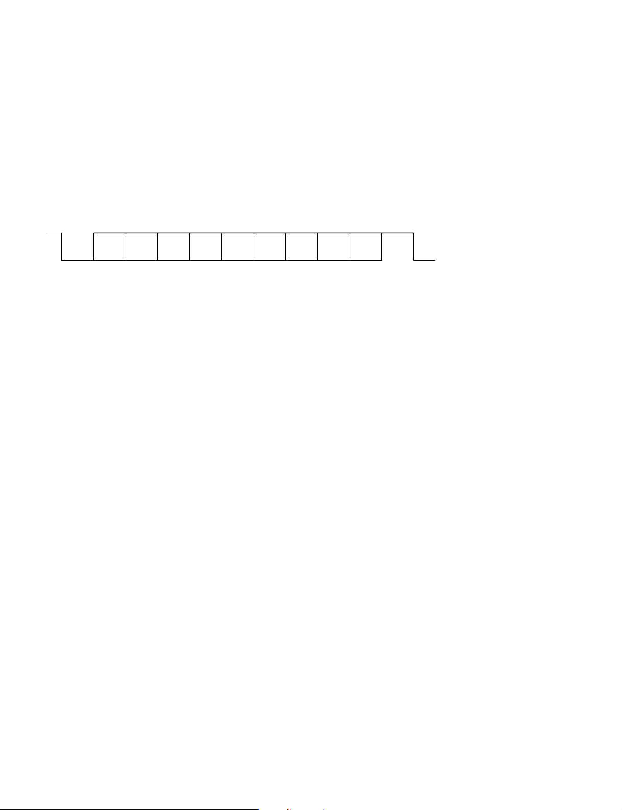
. The bit configuration is defined as follows.
1 START Bit + 8 DATA Bits + 1 PARITY Bit + 1 STOP Bit
START D3D2D1D0
BIT
D4 D5 D6 D7
(MSB)(LSB) (EVEN) BIT
EVEN Parity.....Total number of “1”s from D0 to D7 is an even number.
PARITY STOP
2
VPL-PX20/PX30
VPL-VW10HT
Page 7

3. Command Block Format
The code from B0 to B (n) + 2 as described below are transmitted.
1
B0
Start Code
2
B1
Peripheral Index
B6
Peripheral Index
B11
Cmd1
B2 B3 B4 B5
Group Index Device Index
SENDER (To) Index
3
B7 B8 B9 B10
Group Index
SENDER (From) Index
4
B12
Cmd2
COMMAND
B13
Cmd3
Device Index
5
B14
Data Length 1
(B16 + 2)
(02 _ 81 h)
Check Data Length
Bn
Data (n)
9
Bm + 1
Check SUM
0
Bm + 2
End Code
8
Bm
Data (n + 1, 2, 3, 4...)
Data
67
B15 B16
Data Length 2
(00 h)
Total Data Length
Data Length
Bn = B16 + 1
Bm = B16 + Total Data Length
Data Length 3
(00 _ 7 Fh)
B16
VPL-PX20/PX30
VPL-VW10HT
3
Page 8

4. Data of Code
11
1 Start Condition
11
Bn
B0
22
2 INDEX Header
22
NAME
Start Code
/*-- RECEIVER INDEX --*/
B1
B2
B3
B4
B5
PERIPHERAL INDEX
GROUP INDEX UPPER BYTE
GROUP INDEX LOWER BYTE
DEVICE INDEX UPPER BYTE
DEVICE INDEX LOWER BYTE
/*-- SENDER INDEX --*/
B6
B7
B8
B9
B10
PERIPHERAL INDEX
GROUP INDEX UPPER BYTE
GROUP INDEX LOWER BYTE
DEVICE INDEX UPPER BYTE
DEVICE INDEX LOWER BYTE
/*-- Command --*/
B11
B12
B13
CMD1
CMD2
CMD3
DATE
(hex)
A5
01
00
01
00
01
03
00
01
00
01 - 63
00
80
90
NOTE
Indicates the first packet
01: Projector
Group Index = 0001 hex
Device Index = 0001 hex
01: Controller
Group Index = 0001 hex
Device Index = 0001 - 0063 hex
Refer to attached
Refer to attached
Projector All
LCD Projector All
VPL-PX20, VPL-PX30, VPL-VW10HT only
Note: CMD1 and CMD2 are assigned with different commands for each unit. Consequently,
there is no compatibility of commands between units. For details of the commands, refer
to the respective list of commands for the units. Since there is no index function of this
unit, the receiver INDEX will be ignored even if the command is designated.
33
3 Sub Data Size
33
B14 Data Length 1
02 81 (B16 + 2) hex Data Size
Note: Error when 82 to FF hex codes are included.
44
4 Data Size 2
44
B15 Data Length 2
00 0: Fixed
Note: Error when 01 to FF hex codes are included.
4
VPL-PX20/PX30
VPL-VW10HT
Page 9

55
5 Data Size 3
55
B16 Data Length 3
00 7F Size of 6
Note: Error when 80 to FF hex codes are included.
66
6 Data
66
Bn - Bm Data
XX No Data in some cases
Bn = B16 + 1
Bm = B16 + Total Data Length
77
7 Check SUM
77
Bm + 1 Check Sum
XX
XOR is the exclusive OR.
It is as follows when calculated by 1 bit.
Taking A XOR B = C;
ABC
000
101
011
110
Check sum of Data from 2 to 6
(Calculate the XOR of the Data from 2 to 6)
<Example of Calculation>
When 0XA5 (165) and 0XA5 (165) are calculated by XOR;
A5 10100101 (165)
A5 10100101 (165)
Answer 00000000 (0)
When 0XA5 (165) and 0X5A (90) are calculated by XOR;
Answer
A5 10100101 (165)
5A 01011010 (90)
Answer 11111111 (255)
88
8 End Condition
88
Bm + 2 END Code
5A Indicates the last packet
VPL-PX20/PX30
VPL-VW10HT
5
Page 10

5. Connection
<RS-232C Connection>
Communication is enabled by the use of a D-Sub 9 Pin cross (reverse) cable.
The pin assignment of D-Sub 9 Pin and D-Sub 25 Pin is as follows.
D-Sub 9 Pin
Shell = FG
3
2
7
8
6
5
1
4
9
D-Sub 25 Pin
1
2
3
4
5
6
7
8
20
22
Grounding for safety protection or cable shield
FG
Transmission data
TxD
Reception data
RxD
Transmission request
RTS
Transmission permission
CTS
Data set ready
DSR
GND for signal
SG
Data channel signal carrier detection
DCD
Data terminal ready
DTR
Calling display (Presence/absence of calling signal)
RI
Name
Pins indicated as D-Sub 25 Pin are not used.
Assured cable length: 15 m (However, assurance may not be applicable for some cables.)
The software for controlling the projector from a PC is intended for performing transmission and
reception for only the TxD and RxD lines.
Therefore there is no handshake normally performed by RS-232C.
6
VPL-PX20/PX30
VPL-VW10HT
Page 11

6. Communication Procedure
6-1. Outline of Communication
All communication between CONTROLLER (PC, etc.) and DEVICE (PROJECTOR) is performed by the
command block format. Communication is started by the issue of a command at CONTROLLER and
ended when the return data is sent to CONTROLLER after DEVICE receives the command.
CONTROLLER is prohibited from sending several commands at one time. This means that after
CONTROLLER sends one command, it cannot send other commands until DEVICE returns the return
data. DEVICE sends the return data after processing the command. The time from when CONTROLLER
sends the command until the return data is returned differs according to the contents of the command.
In some cases, CONTROLLER may receive data from DEVICE even though it has not sent a command.
(For example, during SYS setting, SIRCS command, and switcher information when switcher is selected.)
Note: When Sircs Direct Command (CMD1 = 17 hex) is sent, return data may not be returned in
some cases.
6-2. Reading the Command Tables
The command tables can be found in Section 9 (page 11).
CMD1 indicates the command category. The ACK from the projector is returned attached with the
command category sent from the controller. However, when errors of the communication line occur, 10
hex (COMMON) will be returned.
CMD2 indicates the command processing method and processing results. 00 hex (SET) is set when
setting data from the controller to the projector or when requesting for data processing. 01 hex (GET) is
set when acquiring data. 2 hex (RETURN) is set when returning the ACK of the command received from
the projector to the controller and when attaching data. 03 hex (ACK) is set when returning only the
processing results.
However, F0 hex (COMM NAK) is set when the command the projector receives from the controller has
a communication line error or checksum inconsistency.
The top of each category indicates the meaning of the data.
VPL-PX20/PX30
VPL-VW10HT
7
Page 12

7. Communication Rules
. When sending a command from CONTROLLER, the return data (CMD1 = 10 hex or CMD1 = each
category value, CMD2 = 03 hex) from PROJECTOR should be received first before sending the next
command. Even if the next command is sent before receiving the return data, since PROJECTOR will
not be able to receive that command, it does not return a response to CONTROLLER. Consequently, no
error code is also sent.
The following lists the approximate waiting times for PROJECTOR to return the return data after
CONTROLLER sends the command.
. When a communication error occurs, PROJECTOR ignores the data received until now, and set into the
reception standby state.
. For undefined commands or commends determined as invalid by PROJECTOR, PROJECTOR will
send the “NAK” return data to CONTROLLER .
. Take note that when data is written when the input signal of PROJECTOR is unstable, that data (value)
will not be incorporated.
. When INDEX specified SIRCS direct command (CMD1 = 17 hex) is transmitted, leave an interval of
45 mSec until the next transmission. (Do not return the return data (ACK, NAK) when the SIRCS
direct command is received.)
8
VPL-PX20/PX30
VPL-VW10HT
Page 13

8. Approximate Return Waiting Times
_
_
_
_
TIME (mSec)
20
20
20
20
20
25
20
CMD1
00
00
01
01
01
03
03
CMD2
00
01
01
00
01
00
00
DATA1
_
_
00
00
00
00
01
DATA2
01, 02
05
05
Note: The times shown in this table are when communication is performed in the condition that it
will not be interrupted by some reason.
VPL-PX20/PX30
VPL-VW10HT
9
Page 14

Page 15

9. Commands
FUNCTION CMD1 CMD2 DATA1 DATA2
ACK EACH ACK 03h ACK/NAK DATA
ADJUST 00h SET 00h ADJ USER NO OPTION DATA
CATEGORY GET 01h
CATEGORY
VALUE
COMMON COMM NAK COMM ERROR
10h F0h
00 ACK 00 DUMMY OO
01 NAK 01 UNDEFINED OO
10 CHECK SUM ERROR
20 FRAMING ERROR OO
30 PARITY ERROR OO
40 OVER RUN ERROR
50 OTHER COMM ERROR
ADJ USER NO
00 FIXED 01 INPUT OO02 FIXED 00 FIXED 00 VIDEO
00 FIXED 10 CONTRAST OO02 FIXED 00 FIXED 00~64 0~100 O_____OOO
00 FIXED 11 BRIGHTNESS OO02 FIXED 00 FIXED 00~64 0~100 O_____OOO
00 FIXED 12 COLOR OO02 FIXED 00 FIXED 00~64 0~100 O_____OOO
00 FIXED 13 HUE OO02 FIXED 00 FIXED 00~64 0~100 O_____OOO
00 FIXED 14 SHARPNESS OO02 FIXED 00 FIXED 00~64 0~100 O_____OOO
00 FIXED 15 RGB ENHANCER OO02 FIXED 00 FIXED 00~64 0~100 O_____OOO
00 FIXED 16 VOLUME O 02 FIXED 00 FIXED 00~64 0~100 O_____OOO
00 FIXED 17 COL TEMP O 02 FIXED 00 FIXED 00 HIGH O__ ___O__
00 FIXED 20 ASPECT O 02 FIXED 00 FIXED 00 16:9 O________
00 FIXED 21 SCAN CONV OO02 FIXED 00 FIXED 00 OFF O________
00 FIXED 30 PICTURE MUTING OO02 FIXED 00 FIXED 00 OFF O__ __OOOO
00 FIXED 31 AUDIO MUTING O 02 FIXED 00 FIXED 00 OFF O__ __OOOO
COMMAND
04 SIZE ERROR OO
05 SELECT ERROR OO
06 RANGE OVER OO
0A NOT APPLICABLE OO O_____OOO
PX20/30 VW10
OO O_____OOO
OO
OO
OO 01 S VIDEO
OO 02 INPUT A
OO 03 INPUT B
O 01 LOW
O 00 HIGH
O 01 LOW
O 02 CUSTOM1
O 03 CUSTOM2
O 04 CUSTOM3
O 05 CUSTOM4
O 01 4:3
O 00 FULL
O 01 FULL THROUGH
O 02 NORMAL
O
O 04 ZOOM
O 05 SUB TITLE
O 06 WIDE ZOOM
OO 01 ON
OO 01 ON
O 01 ON
DATA3 DATA4 DATA5 DATA6
03 NORMAL THROUGH
DATA7
DATA8 DATA9 Power Status
VPL-PX20/PX30
VPL-VW10HT
11
11
Page 16

FUNCTION CMD1 CMD2 DATA1 DATA2
00 FIXED 32 INPUT-A OO02 FIXED 00 FIXED 00 COMPUTER
00 FIXED 33 INPUT-B O 02 FIXED 00 FIXED 00 COMPUTER O________
00 FIXED 80 GAIN RED OO02 FIXED 00 FIXED 00~FF 0~255 O____ _OOO
00 FIXED 81 GAIN GREEN OO02 FIXED 00 FIXED 00~FF 0~255 O____ _OOO
00 FIXED 82 GAIN BLUE OO02 FIXED 00 FIXED 00~FF 0~255 O____ _OOO
00 FIXED 83 BIAS RED OO02 FIXED 00 FIXED 00~FF 0~255 O____ _OOO
00 FIXED 84 BIAS GREEN OO02 FIXED 00 FIXED 00~FF 0~255 O_____OOO
00 FIXED 85 BIAS BLUE OO02 FIXED 00 FIXED 00~FF 0~255 O_____OOO
REPLY 02h ADJ USER NO VALID LOWER UPPER DATA
00 FIXED 01 INPUT OO00 FIXED 00 00 00 03 00 FIXED 00 VIDEO
00 FIXED 10 CONTRAST OO00 FIXED 00 00 00 64 00 FIXED 00~64 0~100 O_____OOO
00 FIXED 11 BRIGHTNESS OO00 FIXED 00 00 00 64 00 FIXED 00~64 0~100 O_____OOO
00 FIXED 12 COLOR OO00 FIXED 00 00 00 64 00 FIXED 00~64 0~100 O_____OOO
00 FIXED 13 HUE OO00 FIXED 00 00 00 64 00 FIXED 00~64 0~100 O____ _OOO
00 FIXED 14 SHARPNESS OO00 FIXED 00 00 00 64 00 FIXED 00~64 0~100 O_____OOO
00 FIXED 15 RGB ENHANCER OO00 FIXED 00 00 00 64 00 FIXED 00~64 0~100 O____ _OOO
00 FIXED 16 VOLUME O 00 FIXED 00 00 00 64 00 FIXED 00~64 0~100 O_____OOO
00 FIXED 17 COL TEMP O 00 FIXED 00 00 00 01 00 FIXED 00 HIGH O____ _O__
00 FIXED 20 ASPECT O 00 FIXED 00 00 00 01 00 FIXED 00 16:9 O________
00 FIXED 21 SCAN CONV OO00 FIXED 00 00 00 01 00 FIXED 00 OFF O________
00 FIXED 30 PICTURE MUTING OO00 FIXED 00 00 00 01 00 FIXED 00 OFF O____OOOO
00 FIXED 31 AUDIO MUTING O 00 FIXED 00 00 00 01 00 FIXED 00 OFF O____OOOO
00 FIXED 32 INPUT-A OO00 FIXED 00 00 00 03 00 FIXED 00 COMPUTER
PX20/30 VW10
OO 01 COMPONENT
OO 02 DTV-YPBPR
OO 03 DTV-GBR
O 01 COMPONENT
O 02 DTV-YPBPR
O 03 DTV-GBR
OO 01 S VIDEO
OO 02 INPUT A
OO 03 INPUT B
O 01 LOW
O 00 FIXED 00 00 00 05 00 FIXED 00 HIGH
O 01 LOW
O 02 CUSTOM1
O 03 CUSTOM2
O 04 CUSTOM3
O 05 CUSTOM4
O 01 4:3
O 00 FIXED 00 00 00 06 00 FIXED 00 FULL
O 01 FULL THROUGH
O 02 NORMAL
O
O 04 ZOOM
O 05 SUB TITLE
O 06 WIDE ZOOM
OO 01 ON
OO 01 ON
O 01 ON
OO 01 COMPONENT
OO 02 DTV-YPBPR
OO 03 DTV-GBR
DATA3 DATA4 DATA5 DATA6
DATA7
DATA8 DATA9 Power Status
03 NORMAL THROUGH
12
12
VPL-PX20/PX30
VPL-VW10HT
Page 17

FUNCTION CMD1 CMD2 DATA1 DATA2
PX20/30 VW10
DATA3 DATA4 DATA5 DATA6
00 FIXED 33 INPUT-B O 00 FIXED 00 00 00 03 00 FIXED 00 COMPUTER O________
O 01 COMPONENT
O 02 DTV-YPBPR
O 03 DTV-GBR
00 FIXED 80 GAIN RED OO00 FIXED 00 00 00 FF 00 FIXED 00~FF 0~255 O_____OOO
00 FIXED 81 GAIN GREEN OO00 FIXED 00 00 00 FF 00 FIXED 00~FF 0~255 O_____OOO
00 FIXED 82 GAIN BLUE OO00 FIXED 00 00 00 FF 00 FIXED 00~FF 0~255 O_____OOO
00 FIXED 83 BIAS RED OO00 FIXED 00 00 00 FF 00 FIXED 00~FF 0~255 O_____OOO
00 FIXED 84 BIAS GREEN OO00 FIXED 00 00 00 FF 00 FIXED 00~FF 0~255 O_____OOO
00 FIXED 85 BIAS BLUE OO00 FIXED 00 00 00 FF 00 FIXED 00~FF 0~255 O_____OOO
SYSTEM 01h GET 01h DU USER NO DATA SIZE
STATUS
CATEGORY
REPLY 02h DU USER NO DATA SIZE DATA 0
00 FIXED 01 ERROR STATUS OO01 FIXED 00 NO ERROR
OO 01 LAMP ERROR
OO 02 FAN ERROR
OO 04 COVER ERROR
OO 08 TEMP ERROR
OO 10 D5V ERROR
OO 20 POWER ERROR
OO 40 WARNING TEMP
00 FIXED 02 POWER STATUS OO01 FIXED 00 STANBY
OO 01 MAIN ON EXE
OO 02 D5V CHECK
OO 03 D5V ON EXE
OO 04 FAN ON EXE
OO 05 LAMP ON EXE
OO 06 LAMP ON CHECK
OO 07 LAMP NG WAIT
OO 08 ON EXE
OO 09 ON
OO 0A LAMP OFF EXE
OO 0B COOLING1
OO 0C COOLING2
OO 0D FAN OFF EXE
OO 0E OFF EXE
OO
0F SAVING LAMPOFF EXE
OO 10 SAVING1
OO 11 SAVING2
OO 12 SABING STANBY
SET 00h DU USER NO DATA SIZE DATA 0
GET 01h DU USER NO DATA SIZE
REPLY 02h DU USER NO DATA SIZE DATA 0
00 FIXED 05 CONTROL MODE OO01 FIXED 00 USER
SELECT OO 01 SERVICE
SIRCS CODE 17HEX 00HEX CATEGORY SIRCS CODE REPEAT REPEAT NUMBER
DIRECT
85 5A 20BIT PJ SIRCS
CODE (2BYTES) OO
00~7F SEE ATTACHED
00 ONE SHOT REPEAT NUMBER O_
01 REPEAT (2BYTES)
40 54 15BIT PJ SIRCS
CODE (2BYTES) OO
DATA7
DATA8 DATA9 Power Status
Same
Same
process
process
as the
as the
usual
usual
Sircs
Sircs
PS
state
cleared
Same
process
as the
usual
Sircs
Same
process
as the
usual
Sircs
Same
process
as the
usual
Sircs
Same
process
as the
usual
Sircs
VPL-PX20/PX30
VPL-VW10HT
13
13
Page 18

FUNCTION CMD1 CMD2 DATA1 DATA2
MEMORY 03h SET 00h RESET MEMORY NO
CATEGORY
00 RESET 01 Channel Memory OO
02 Status Memory OO
03 Set Memory OO
SAVE MEMORY NO
01 SAVE 04 W/B ALL OO
05 W/B LOW OO
06 W/B HIGH OO
07 W/B CUSTOM1 O
08 W/B CUSTOM2 O
09 W/B CUSTOM3 O
0A W/B CUSTOM4 O
PX20/30 VW10
DATA3 DATA4 DATA5 DATA6
DATA7
DATA8 DATA9 Power Status
14
14
VPL-PX20/PX30
VPL-VW10HT
Page 19

SIRCS CODE
15Bit Category
x0 x1 x2 x3 x4 x5 x6 x7 x8 x9 xA xB xC xD xE xF
0x
1x VOLUME VOLUME AUDIO POWER CONTRAST CONTRAST COLOR COLOR BRITNESS BRITNESS
2x HUE HUE SHARPNESS SHARPNESS PICTURE STATUS STATUS MENU VIDEO INPUT A INPUT B POWER POWER
+_+_MUTING ON OFF ON OFF
PURPLISH GREENISH SHARP SOFT
3x CURSOR CURSOR CURSOR CURSOR
4x ADJ ADJ ADJ RGB SIZE RGB SHIFT
RGB
5x W/B W/B INPUT BLANKING ENTER MEMORY S VIDEO
6x
7x RESET
20Bit Category
x0 x1 x2 x3 x4 x5 x6 x7 x8 x9 xA xB xC xD xE xF
0x
1x
2x
3x
4x
5x
6x APA DOT HELP FUNCTION 1 FUNCTION 2 DIGITAL DIGITAL
7x
Bold: PX20/PX30 only
Italic
: VW10HT only
VIDEO VIDEO VIDEO VIDEO VIDEO VIDEO VIDEO VIDEO
MEMORY MEMORY 1 MEMORY 2 MEMORY 3 MEMORY 4 MEMORY 5 MEMORY 6 MEMORY
OFF TOGGLE
PHASE ZOOM
++
+
++
UP DOWN HIGH LOW HIGH LOW BRIGHT DARK
GAIN BIAS SELECT
__
_ MUTING ON/OFF +_+_ +_
__
→←↑ ↓
PATTERN
++
+ ZOOM
++
__
_
__
PX20/PX30/VW10HT Communication Basic Structure
NO COMMAND NAME RS232C CMD1 CMD2 DATA1 DATA2 DATA3 DATA4 DATA5 DATA6 DATA7 DATA8 DATA9 ~ Data n
1 ADJUST CATEGORY SET 00h 00h ADJ USER NO OPTION DATA
GET 01h ADJ USER NO
REPLY 02h ADJ USER NO STATUS LOWER UPPER DATA
ACK 03h ACK/NAK DATA
2
SYSTEM STATUS CATEGORY
3 SIRCS SET 17h 00h CATEGORY SIRCS CODE REPEAT REPEAT NUMBER
4 MEMORY CATEGORY REQUEST 03h 00h SAVE/RESET MEMORY NO
VPL-PX20/PX30
VPL-VW10HT
SET 01h 00h DU USER NO DATA SIZE DATA [0] DATA [1] ~ ~ ~ ~ ~ DATA [n-1]
GET 01h DU USER NO DATA SIZE
REPLY 02h DU USER NO DATA SIZE DATA [0] DATA [1] ~ ~ ~ ~ ~ DATA [n-1]
ACK 03h ACK/NAK DATA
ACK 03h ACK/NAK DATA
15
15
 Loading...